- 2014 Toyota Tacoma Owners Manuals
- Toyota Tacoma Owners Manuals
- 2005 Toyota Tacoma Owners Manuals
- Toyota Tacoma Owners Manuals
- 2000 Toyota Tacoma Owners Manuals
- Toyota Tacoma Owners Manuals
- 2007 Toyota Tacoma Owners Manuals
- Toyota Tacoma Owners Manuals
- 2016 Toyota Tacoma Owners Manuals
- Toyota Tacoma Owners Manuals
- 2006 Toyota Tacoma Owners Manuals
- Toyota Tacoma Owners Manuals
- 2008 Toyota Tacoma Owners Manuals
- Toyota Tacoma Owners Manuals
- 2009 Toyota Tacoma Owners Manuals
- Toyota Tacoma Owners Manuals
- 2015 Toyota Tacoma Owners Manuals
- Toyota Tacoma Owners Manuals
- 2001 Toyota Tacoma Owners Manuals
- Toyota Tacoma Owners Manuals
- 2012 Toyota Tacoma Owners Manuals
- Toyota Tacoma Owners Manuals
- 2004 Toyota Tacoma Owners Manuals
- Toyota Tacoma Owners Manuals
- 2011 Toyota Tacoma Owners Manuals
- Toyota Tacoma Owners Manuals
- 2003 Toyota Tacoma Owners Manuals
- Toyota Tacoma Owners Manuals
- 2002 Toyota Tacoma Owners Manuals
- Toyota Tacoma Owners Manuals
- 2010 Toyota Tacoma Owners Manuals
- Toyota Tacoma Owners Manuals
- Download PDF Manual
-
er, and only when it is deemed necessary
(cid:1) Disclose summarized data cleared of vehicle identifi- cation information to a non- Toyota organization for research purposes
New vehicle warranty
Your new vehicle is covered by the following Toyota limited warranties:
(cid:1) New vehicle warranty (cid:1) Emission control systems warranty (cid:1) Others further
information, please refer
Information Booklet” or
For Warranty Supplement”.
to the “Owner’s “Owner’s Manual
Your responsibility for
maintenance
It is the owner’s responsibility to make sure that the speci- fied maintenance is performed. Section 6 gives details of these maintenance requirements. Also included in Section 6 is general maintenance. For scheduled maintenance in- formation, please refer to the “Scheduled Maintenance Guide” or “Owner’s Manual Supplement”.
2005 TACOMA from Mar. ’05 Prod. (OM35862U)
05 02.25
Important health and safety
information about your Toyota
Accessories, spare parts and modification of your Toyota
CAUTION
(cid:1) WARNING: Engine exhaust, some of its constitu- ents, and a wide variety of automobile compo- nents contain or emit chemicals known to the State of California to cause cancer and birth de- fects and other reproductive harm. In addition, oils, fuels and fluids contained in vehicles as well as waste produced by component wear con- tain or emit chemicals known to the State of California to cause cancer and birth defects or
other reproductive harm.
(cid:1) Battery posts, terminals and related accessories contain lead and lead compounds. Wash your hands after handling. Used engine oil contains chemicals that have caused cancer in laboratory animals. Always protect your skin by washing
thoroughly with soap and water.
A wide variety of non- genuine spare parts and accessories for Toyota vehicles are currently available in the market. You should know that Toyota does not warrant these prod- ucts and is not responsible for their performance, repair, or replacement, or for any damage they may cause to, or adverse effect they may have on, your Toyota vehicle.
This vehicle should not be modified with non- genuine Toyota products. Modification with non- genuine Toyota products could affect its performance, safety or durability, and may even violate governmental regulations. In addi- tion, damage or performance problems resulting from the modification may not be covered under warranty.
vi
2005 TACOMA from Mar. ’05 Prod. (OM35862U)
05 02.25
(cid:1) Traction control system (cid:1) “AUTO LSD” system (cid:1) Vehicle stability control system (cid:1) Downhill assist control system (cid:1) Hill- start assist control system
(automatic transmission only)
(cid:1) Cruise control system (cid:1) Anti- lock brake system (cid:1) Electronic throttle control system
Spark ignition system of your
Toyota
The spark ignition system in your Toyota meets all require- ments of the Canadian Interference- Causing Equipment Standard.
Installation of a mobile two- way radio system
As the installation of a mobile two- way radio system in your vehicle could affect the following electronic systems, be sure to check with your Toyota dealer for precautionary measures or special instructions regarding installation.
(cid:1) Multiport
fuel
injection system/sequential multiport
fuel injection system
(cid:1) SRS airbag system (cid:1) Seat belt pretensioner system
vii
2005 TACOMA from Mar. ’05 Prod. (OM35862U)
05 02.25
Tires and loading on your
Scrapping of your Toyota
Toyota
Underinflated or overinflated tire inflation pressure and the excess load may result in the deterioration of steering ability and braking ability, leading to an accident. Check the tire inflation pressure periodically and be sure to keep the load limits given in this Owner’s Manual. For details about tire limits, see “Checking tire inflation pressure” on page 350 in Section 7- 2 and “Vehicle load limits” on page 277
in Section 2.inflation pressure and
load
If
The SRS airbag and seat belt pretensioner devices in your Toyota contain explosive chemicals. is scrapped with the airbags and pretensioners left as they are, this may cause an accident such as fire. Be sure to have the systems of the SRS airbag and seat belt preten- sioner removed and disposed of by a qualified service shop or by your Toyota dealer before you dispose of your vehicle.
the vehicle
viii
2005 TACOMA from Mar. ’05 Prod. (OM35862U)
05 02.25
On- pavement and off- road
driving tips
(four- wheel drive models and
PreRunner)
This vehicle will handle and maneuver differently from an ordinary passenger car because it is also designed for off- road use. It has a significantly higher rollover rate than other types of vehicles. In addition, this vehicle has a higher ground clearance and center of gravity than that of an ordinary passenger car. This vehicle design feature causes this type of vehicle to be more likely to rollover. Failure to operate this vehicle correctly may result in loss of control, accidents or vehicle rollover causing death or serious “Off- road vehicle precautions” on page 252 in Section 2 and “Off- road driving precautions” on page 284 in Section 3.
injury. Be sure
read
to
Leak detection pump
This pump performs fuel evaporation leakage check. This check is done approximately five hours after the engine is turned off. So you may hear sound coming from under- neath the deck for several minutes. It does not indicate a malfunction.
ix
2005 TACOMA from Mar. ’05 Prod. (OM35862U)
05 02.25
2005 TACOMA from Mar. ’05 Prod. (OM35862U)
05 02.25
You should know as much about the quality and importance of proper maintenance of your new vehicle as the people who built it.
The Toyota authorized Repair Manual tells you how to maintain your vehicle and enables you to correctly perform your own maintenance.
The best way to keep your new vehicle in top running order is to maintain it properly from the moment you drive it off the showroom floor.
The Toyota authorized Repair Manual is packed with literally everything you need to know to perform your own maintenance in virtually every area of your new vehicle.
2005 TACOMA from Mar. ’05 Prod. (OM35862U)
05 02.25
Maintenance procedures for the engine, chassis, body, electrical system, and more, are clearly explained and illustrated.
Periodic maintenance and tune-up
Periodic maintenance and tune- up helps to pre- vent small problems from growing into larger ones lat- er on. The repair manual outlines exactly what main- tenance is required and clearly explains how to do the work yourself step- by- step.
Areas covered include such things as spark plug re- placement, valve clearance adjustment and engine oil and filter replacement.
Where to obtain the
Repair Manual
The repair manual for TOYOTA TACOMA may be purchased from any Toyota dealer or the Material Distribution Center. To purchase the repair manual, please contact your Toyota deal- er or call the Material Distribution Center toll- free at 1- 800- 622- 2033.
2005 TACOMA from Mar. ’05 Prod. (OM35862U)
05 02.25
WE REALLY CARE ABOUT YOU (cid:1) PLEASE BUCKLE UP
Toyota has made a special effort to encourage use of seat belts.
Toyota belts are:
(cid:1) Comfortable (cid:1) Easy to use (cid:1) Convenient
We encourage you to use your belts every time you drive.
2005 TACOMA from Mar. ’05 Prod. (OM35862U)
05 02.25
SECTION 1- 1
OPERATION OF INSTRUMENTS AND CONTROLS Overview of instruments and controls Instrument panel overview Instrument cluster overview Indicator symbols on the instrument panel
. . . . . . . . . . . . . . . . . . . . . . . . . . . . . . . . . . . . . . . . . . . . . . . . . . . . . . . . . . . . . . . . . . . . . . . . . . . . . . . . . . . . . . . . . . . . . . . .
2005 TACOMA from Mar. ’05 Prod. (OM35862U)
05 02.25
Instrument panel overview (cid:1)Bench seat
1. Side vents 2. Instrument cluster 3. Center vents 4. Glove box 5. Automatic transmission selector lever
or manual transmission gear shift lever
6. Cup holders 7. Auxiliary box 8. Hood lock release lever 9. Parking brake pedal
(automatic transmission)
LS11001a
2005 TACOMA from Mar. ’05 Prod. (OM35862U)
05 02.25
(cid:1)Separate seats with automatic transmission
LS11002a
1. Side vents 2. Instrument cluster 3. Center vents 4. Garage door opener box or accessory
meter
5. Personal lights 6. Auxiliary boxes 7. Power door lock switches 8. Power window switches 9. Glove box 10. Automatic transmission selector lever 11. Rear console box 12. Bottle holders 13. Cup holders 14. Hood lock release lever 15. Parking brake pedal 16. Window lock switch
2005 TACOMA from Mar. ’05 Prod. (OM35862U)
05 02.25
(cid:1)Separate seats with manual transmission
LS11003a
1. Side vents 2. Instrument cluster 3. Center vents 4. Garage door opener box or accessory
meter
5. Personal lights 6. Auxiliary boxes 7. Power door lock switches 8. Power window switches 9. Glove box 10. Rear console box 11. Bottle holders 12. Cup holders 13. Manual transmission gear shift lever 14. Hood lock release lever 15. Window lock switch
2005 TACOMA from Mar. ’05 Prod. (OM35862U)
05 02.25
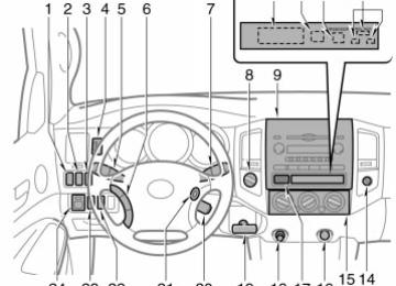
LS11004a
1. Front fog light switch 2. Rear differential lock switch or “AUTO
LSD” switch
3. Power outlet main switch 4. Instrument panel light control dial 5. Headlight and turn signal switches 6. Audio remote control switches 7. Wiper and washer switches 8. Front drive control switch knob 9. Audio system 10. Clock 11. Engine immobilizer system indicator
light
12. Front passenger’s seat belt reminder
light
13. Front passenger occupant classification indicator lights or passenger airbag on- off indicator lights
14. Passenger airbag manual on- off switch 15. Air conditioning controls 16. Power outlet 17. Emergency flasher switch 18. Cigarette lighter 19. Parking brake lever (manual
transmission)
2005 TACOMA from Mar. ’05 Prod. (OM35862U)
05 02.25
20. Cruise control switch 21. Ignition switch 22. Clutch start cancel switch 23. “DAC” switch 24. Power rear view mirror control switches
2005 TACOMA from Mar. ’05 Prod. (OM35862U)
05 02.25
Instrument cluster overview
LS11005
1. Tachometer 2. Speedometer 3. Odometer and two trip meters
4. Service reminder indicators and
indicator lights
5. Engine coolant temperature gauge 6. Fuel gauge
7. Trip meter reset knob 8. Shift position indicator lights (automatic
transmission)
2005 TACOMA from Mar. ’05 Prod. (OM35862U)
05 02.25
Indicator symbols on the instrument panel
Brake system warning light* 1
Driver’s seat belt reminder light* 1
Front passenger’s seat belt reminder light* 1
Front passenger occupant classification indicator light or passenger airbag on- off indicator light
Discharge warning light* 1
Low engine oil pressure warning light* 1
Malfunction indicator lamp* 1
Engine oil replacement reminder light* 1 (for vehicles sold in U.S.A.)
or
Anti- lock brake system warning light* 1
(cid:2) Vehicle stability control system warning
(cid:2) Traction control system warning light* 1
(cid:2) “AUTO LSD” system warning light* 1
(cid:2) Downhill assistcontrol
system warning
light* 1
light* 1
(cid:2) Hill- start assist control system warning
light* 1
Open door warning light* 1
SRS warning light* 1
2005 TACOMA from Mar. ’05 Prod. (OM35862U)
05 02.25
Automatic transmission fluid temperature warning light* 1
Low speed four- wheel drive indicator light* 3
Engine immobilizer system indicator light* 1
Rear differential lock indicator light* 4
Headlight low beam indicator light
Slip indicator light
Tail light indicator light
Vehicle stability control system off indicator light
Headlight high beam indicator light
Downhill assist control system indicator light
Turn signal indicator lights
Automatic transmission indicator lights (5- speed)
Automatic transmission indicator lights (4- speed)
Four- wheel drive indicator light* 3
“AUTO LSD” indicator light
Cruise control indicator light* 2
* 1: For details, see “Service reminder indicators and warning
buzzers” on page 147 in Section 1- 6.
* 2: If this light flashes, see “Cruise control” on page 187 in
Section 1- 7.
* 3: If this light flashes, see “Four- wheel drive system” on page
169 in Section 1- 7.
* 4: If this light flashes, see “Rear differential lock system” on
page 185 in Section 1- 7.
2005 TACOMA from Mar. ’05 Prod. (OM35862U)
05 02.25
10
2005 TACOMA from Mar. ’05 Prod. (OM35862U)
05 02.25
SECTION 1- 10
OPERATION OF INSTRUMENTS AND CONTROLS Other equipment Accessory meter Clock Cigarette lighter Power outlet Glove box Garage door opener box Auxiliary boxes Rear console box Cup holders Bottle holders Storage boxes Flashlight holder Seatback table Cargo net hooks Grocery bag hooks Deck hooks Deck rails Floor mat
. . . . . . . . . . . . . . . . . . . . . . . . . . . . . . . . . . . . . . . . . . . . . . . . . . . . . . . . . . . . . . . . . . . . . . . . . . . . . . . . . . . . . . . . . . . . . . . . . . . . . . . . . . . . . . . . . . . . . . . . . . . . . . . . . . . . . . . . . . . . . . . . . . . . . . . . . . . . . . . . . . . . . . . . . . . . . . . . . . . . . . . . . . . . . . . . . . . . . . . . . . . . . . . . . . . . . . . . . . . . . . . . . . . . . . . . . . . . . . . . . . . . . . . . . . . . . . . . . . . . . . . . . . . . . . . . . . . . . . . . . . . . . . . . . . . . . . . . . . . . . . . . . . . . . . . . . . . . . . . . . . . . . . . . . . . . . . . . . . . . . . . . . . . . . . . . . . . . . . . . . . . . . . . . . . . . . . . . . . . . . . . . . . . . . . . . . . . . . . . . . . . . . . . . . . . . . . . . . . . . . . . . . . . . . . . . . . . . . . . . . . . . . . . . . . . . . . . . . . . . . . . . . . . . . . . . . . . . . . . . . . . . . . . . . . . . . . . . . . . . . . . . . . . . . . . . . . . . . . . . . . . . . . . . . . . . . . . . . . . . . . . . . . . . . . . . . . . . . . . . . . . . . . . . . . . . . . . . . . . . . . . . . . . . . . . . . . . . . . . . . . . . . . . . . . . . . . . . . . . . . . . . . . . . . . . . . . . . . . . . . . . . . . . . . . . . . . . . . . . . . . . . . . . . . . . . . . . . . . . . . . . . . . . . . . . . . . . . . . . . . . . . . . . . . . . . . . . . . . . . . . . . . . . . . . . . . . . . . . . . . . . . . . . . . . . . . . . . . . . . . . . . . . . . . . . . . . . . . . . . . . . . . . . . . . . . . . . . . . . . . . . . . . . . . . . . . . . . . . . . . . .
226
231
231
231
236
236
239
241
241
243
244
244
245
245
246
246
246
2492005 TACOMA from Mar. ’05 Prod. (OM35862U)
225
05 02.25
Accessory meter—
LS10034
1. “E/M” button 2. Compass 3. Outside temperature display
the
—Before using the accessory meter Operate the accessory meter with the ignition switch on. to When “ON”, the last previously used mode dis- played just before the ignition switch is turned off will appear. When lights are turned on, the brightness of the display will be reduced.
instrument panel
ignition switch
turned
the
is
“E/M” button This button is used to switch between English/U.S. Customary System and metric units of the outside temperature display. Every time you push this button, the dis- play toggles through the following informa- tion. 1. Compass and outside temperature ((cid:2)F) 2. Compass and outside temperature ((cid:2)C) 3. Display off (no compass) The display variations are as follows;
Indication
Outside
temperature
English/U.S. System (E)
Customary
Metric (M)
(cid:2)F
(cid:2)C
The initial mode will be English/U.S. Cus- tomary System units, however, if the unit is switched ignition switch is off, it will display metric units when the ignition switch is turned to “ON”.
to metric and
the
226
2005 TACOMA from Mar. ’05 Prod. (OM35862U)
05 02.25
—Outside temperature display
—Compass
LS10035
LS10036
temperature
the unit, push the “E/M” button
The outside temperature display indi- cates the outside air temperature. The displayed value is updated. To set until the desired unit display appears. The displayed ranges - 30(cid:2)C (- 22(cid:2)F) up to 50(cid:2)C (122(cid:2)F). If an abnormality exists in the connection of temperature sensor, “- - (cid:2)C” (“- - (cid:2)F”) will appear on the display. If “- - (cid:2)C” (“- - (cid:2)F”) appears on the display, contact your Toyota dealer. There may be a case that “- - (cid:2)C” (“- - (cid:2)F”) appears momentarily when the ignition is quickly turned to “ON”. It is normal if it goes out soon.
the outside air
from
indicates
the vehicle
is heading.
the direction The compass that the above case, it shows that the vehicle is heading west. The direction display is updated every 2
seconds.In
Displays
NE SE SW NW
Directions
North
Northeast
East
Southeast
South
Southwest
West
Northwest
The compass may not show the correct direction in the following conditions: (cid:1) The vehicle is stopped immediately af-
ter turning.
(cid:1) The compass does not adjust while the
vehicle is stopped.
(cid:1) The ignition switch is turned off imme-
diately after turning.
(cid:1) The vehicle is on an inclined surface. (cid:1) The vehicle is in a place where the earth’s magnetic field is subject to in- terference by artificial magnetic fields (underground parking, under a steel tower, between buildings, roof parking, near a crossing, near a large vehicle, etc.).
(cid:1) The vehicle is magnetized. (There is a magnet or a metal object on or near the roof.)
is small,
the deviation
(cid:1) The battery has been disconnected. If the compass works to calibrate the direction automati- cally while the vehicle is in motion. For additional precision or see calibrating, COMPASS” below.
for complete THE
“CALIBRATING
2005 TACOMA from Mar. ’05 Prod. (OM35862U)
227
05 02.25
the direction
If the system does not operate properly, contact your Toyota dealer.
indicated or
is not
LS10037
Compass sensor
The compass sensor is on the roof of the vehicle.
NOTICE
Do not put magnets or a metal object on or near the roof of the vehicle. Doing this may cause malfunction of the compass sensor.
the
from
CALIBRATING THE COMPASS (deviation calibration) the compass The direction display on deviates true direction deter- mined by the earth’s magnetic field. The angle of deviation varies according to the geographic position of the vehicle. To adjust this deviation, stop the vehicle, then push and hold the “E/M” button until the “VAR” indication appears on the com- pass display. Then push the “E/M” button, referring to the following map to select the number of the zone where the vehicle is.
228
2005 TACOMA from Mar. ’05 Prod. (OM35862U)
05 02.25
Samoa: 5
Guam: 8
Saipan:
After calibration, leaving the system for several seconds returns to the compass mode.
CAUTION
Do not adjust the display while the vehicle is moving. Be sure to adjust the display only when the vehicle is stopped.
LS10048
Zone number
2005 TACOMA from Mar. ’05 Prod. (OM35862U)
229
05 02.25
LS10038a
LS10039
the direction display on
CALIBRATING THE COMPASS (circling calibration) Sometimes the compass may not change after a turn. To rectify this, stop the vehicle and push and hold the “E/M” button until the “CAL” indi- cation appears on the compass display. (At time, is locked in “N”.)
the compass display
this
in a circle, drive around
Drive the vehicle in a circle at 8 km/h (5
mph) or less. If there is not enough space to drive the block. When the “CAL” indication goes off and the compass returns to the normal mode, calibration is complete. If calibration cannot be performed because of the magnetized vehicle etc., take your vehicle to Toyota dealer.Perform circling calibration just after you have purchased your Toyota. And then always perform circling calibration after the battery has been removed, re- placed or disconnected. (cid:1) Do not perform circling calibration of the compass the earth’s magnetic field is subject to in- terference by artificial magnetic fields (underground parking, under a steel tower, between buildings, roof parking, near a crossing, near a large vehicle, etc.).
in a place where
(cid:1) During calibration, do not operate elec- tric systems (moon roof, power win- dows, etc.) as they may interfere with the calibration.
CAUTION
(cid:1) When doing the circling calibration, be sure to secure a wide space, and watch out for people and ve- hicles in the neighborhood. Do not violate any local traffic rules while performing circling calibration.
(cid:1) Do not adjust the display while the vehicle is moving. Be sure to adjust the display only when the vehicle is stopped.
230
2005 TACOMA from Mar. ’05 Prod. (OM35862U)
05 02.25
Clock
Cigarette lighter
Power outlet (12 VDC)
LS10001
LS10002
LS10003
To reset the hour: Push the “H” button. To reset the minutes: Push the “M” button. The key must be in the “ACC” or “ON” position. If the electrical power source has been disconnected from the clock, the time dis- play will automatically be set to 1:00 (one o’clock). When lights are turned on, the brightness of the time in- dication will be reduced.
instrument panel
the
To use the cigarette lighter, press it in. After it finishes heating up, it automati- cally pops out ready for use. If the engine is not running, the key must be in the “ACC” position. Do not hold the cigarette lighter pressed in. Use a Toyota genuine cigarette lighter or equivalent for replacement.
The power outlet is designed for power supply for car accessories. The key must be in the “ACC” or “ON” position for the power outlets to be used.
NOTICE
(cid:1) To prevent the fuse from being blown, do not use the electricity over the total capacity of 12V/120W. (cid:1) To prevent the battery from being discharged, do not use the power outlets longer than necessary when the engine is not running.
2005 TACOMA from Mar. ’05 Prod. (OM35862U)
231
05 02.25
Power outlet (115 VAC)
(cid:1) Close the power outlet lids when the power outlets are not in use. Inserting anything other than an ap- propriate plug that fits the outlet, or allowing any liquid to get into the outlet may cause electrical fail- ure or short circuits.
LS10005
(a) The maximum capacity
is 115
VAC/400W when the following condi- tion applies:(cid:1) Automatic
transmission models: The selector lever is in the “P” or “N” posi- tion.
(cid:1) Manual transmission models: The shift lever is in the neutral position and the clutch pedal is not depressed.
(b) The maximum capacity
is 115
VAC/100W when the following condi- tion applies:(cid:1) Automatic
transmission models: The selector lever is moved to any posi- tions other than “P” and “N”.
(cid:1) Manual
transmission models:
The
clutch pedal is depressed.
A maximum capacity of 400W can only be restored by turning the power outlet main switch off and then on again under condi- tion (a) described above.
This power outlet is designed for use as a power supply for electric ap- pliances. The power outlet must only be used after the engine is started. If the engine is started with the power outlet main switch on, the maximum ca- pacity of the power supply may decrease to below the standard, or may be cut off completely, even when the vehicle is sta- tionary. While the maximum capacity of the power outlet is always 115 VAC/100W. When the vehicle is stationary, the maximum capacity of the power outlet varies depending on the fol- lowing conditions (a) or (b):
is being driven,
the vehicle
232
2005 TACOMA from Mar. ’05 Prod. (OM35862U)
05 02.25
The protection circuit may be activated to cut the power supply if any of the follow- ing conditions apply: (cid:1) The engine is started with the power
outlet switch on.
(cid:1) Use of electrical appliances exceeding
the maximum capacity is attempted. A sound may be heard when the protection circuit is activated. This is normal and does not indicate a mal- function.
(cid:1) Electrical appliances, which consume power exceeding 100W, have been used continuously for a long time per- iod.
(cid:1) The total power usage by all electrical (headlights, air conditioning, total vehicle for an extended period of
features etc.) has exceeded maximum time.
the
If the protection circuit is activated and the power supply is cut, conduct the fol- lowing procedure: 1. Park the vehicle in a safe area, and then securely apply the parking brake. 2. Check and ensure the following condi-
tions:
Automatic transmission models: The selector lever is in the “P” or “N” posi- tion. Manual transmission models: The shift lever is in the neutral position and the clutch pedal is not depressed.
3. Make sure that the power consumption of the electric appliance is within the maximum capacity of the power outlet and the appliance is not broken.
4. Push again.
the power outlet main switch
the
to cool
When the cabin temperature is high, open the windows temperature down. Once it reaches the normal temper- ature, turn the power outlet main switch on again. If the power supply is not resumed even after performing the above procedure, have the vehicle inspected by a Toyota dealer.
Indicator light (green)
LS10004
Indicator light (yellow)
To use the power outlet, push the main switch located on the instrument panel. The color of the indicator light changes according the maximum available capacity, as follows:
Illumination color
Maximum capacity
Green and yellow
115 VAC/400W
Yellow
115 VAC/100W
turn
To the power outlet off, push the main switch again. When the power outlet is not in use, make sure that the main switch is off and that the indicator light is not illuminated.
2005 TACOMA from Mar. ’05 Prod. (OM35862U)
233
05 02.25
When the power outlet is in operation, the sound of the cooling fan may be heard from the rear console box. This is normal and does not indicate a malfunction. After removing a plug from the power out- let, ensure that lid is properly closed.
the power outlet
CAUTION
(cid:1) Use of the power outlet when it is wet with rain, drinking water or snow may electrical shocks and is extremely dangerous. The power outlet must be thorough- ly dried before use.
result
in
(cid:1) Do not allow children to use or
play with the power outlet.
(cid:1) Be careful not to get any part of your body caught in the power out- let lid.
(cid:1) When using electrical appliances, strictly follow any cautions and no- tices written on their labels and in the manufacturers’ instruction man- uals.
the power outlet or
(cid:1) Do not modify, disassemble or repair its inverter, in any way. Doing so may result in unexpected malfunctions or accidents, which could cause serious damage or injuries. Contact a Toyota dealer for any necessary repairs.
To prevent injuries and accidents, se- curely fix all electric appliances be- fore use and do not use any ap- pliances that may do any of the fol- lowing: (cid:1) Distract the driver while driving, or
hamper safe driving.
(cid:1) Result in a fire or burn injuries due to the appliance rolling, falling or overheating while driving.
(cid:1) Emit steam, while the windows of
the cabin are closed.
Do not perform any of the following. Doing so is very dangerous and may cause unexpected accidents, such as electric shocks. (cid:1) Using the power outlet for electric
heaters while sleeping.
(cid:1) Contaminating the power outlet with liquid substances or mud, or using it in rainy and snowy weather.
(cid:1) Handling electrical appliance plugs at the power outlet with wet hands or feet.
(cid:1) Inserting
foreign objects
into the
power outlet.
(cid:1) Using malfunctioning electric ap-
pliances.
(cid:1) Inserting inappropriate or badly fit-
ting plugs into the power outlet.
234
2005 TACOMA from Mar. ’05 Prod. (OM35862U)
05 02.25
NOTICE
(cid:1) To prevent the battery from being discharged, turn off all the vehicle’s electronic equipment and accesso- ries, such as the headlights, fog lights and air conditioner, when electrical appliances that consume in excess of 100W are used contin- uously for long periods of time.
(cid:1) To prevent any damage caused by heat, do not use any electrical ap- pliances that give off intense heat such as toasters, in any locations including the internal or external trim, seats and deck.
(cid:1) Do not use any electrical ap- pliances, which are easily affected by vibration or heat, inside the ve- hicle. Vibration while driving, or the heat of the sun while parking, may result in damage to those electrical appliances.
(cid:1) Keep the lid closed when the power outlet is not in use. Do not insert any items other than appropriate plugs, as this may cause electrical failure or short circuits.
(cid:1) After inserting a plug, gently close the power outlet lid. Failure to do so may cause damage to the plug. (cid:1) If any electrical appliances are to be used while driving, securely fas- ten both the appliances and their cables to prevent them from falling or getting caught any of the power- train components.
(cid:1) Do not use plug adaptors to con- nect too many plugs to the power outlet.
(cid:1) If the power outlet is loose when an electrical appliance plug is con- nected, replace the outlet. Contact a Toyota dealer for any necessary replacements.
(cid:1) If the power outlet gets dirty, turn the main switch off and use a soft, clean, dry-wet cloth to wipe it gent- ly. Do not use any cleansing materi- als, such as organic solvents, wax, or compound cleaners, as these may damage the power outlet or cause it to malfunction.
(cid:1) Keep the power outlet free from dust and foreign materials and clean it regularly.
The power outlet is not designed for the following electric appliances even if their power consumption is below the maximum capacity. These appliances may not operate properly. (cid:1) Appliances with high initial peak watt- age: cathode- ray tube type televisions, compressor- driven refrigerators, electric tools, etc.
(cid:1) Measuring devices which process pre- cise data: medical equipment, measur- ing instruments, etc.
(cid:1) Other appliances requiring an extremely stable power supply: microcomputer- controlled electric blankets, touch sen- sor lamps, etc.
Use of the power outlet may not be possible if the vehicle battery voltage is low due to decreased battery capacity. The integrated timers of electrical ap- pliances may not function properly when the power supply is cut by the protection circuit.
2005 TACOMA from Mar. ’05 Prod. (OM35862U)
235
05 02.25
Some electrical appliances may not op- erate properly unless they are installed on a level place. The precise power outlet voltage cannot be measured using commercial testers. If necessary, contact a Toyota dealer. Certain electrical appliances may cause radio noise.
Glove box
Garage door opener box
LS10006
LS10007
To open the glove box door, pull the lever.
CAUTION
To reduce the chance of in case of an accident or a sudden stop, always keep the glove box door closed while driving.
injury
The box is designed to store a garage door opener transmitter. Open the cover and remove the Velcro square.
236
2005 TACOMA from Mar. ’05 Prod. (OM35862U)
05 02.25
LS10008
LS10009
LS10010
Remove the paper strip covering the adhe- sive on back side of square and adhere the square to back side of the transmitter near the center.
Please note if transmitter has wire clip for sun visor, this clip must be removed prior to adhesion of the Velcro.
Place the transmitter with Velcro square facing inside of box into the box. Make sure located above button pins.
transmitter button
the
is
2005 TACOMA from Mar. ’05 Prod. (OM35862U)
237
05 02.25
LS10011
LS10012
LS10013
Remove spacers from the center panel. Place one spacer on the pin that would be below transmitter button when the cover is closed. Close the cover.
When the garage door opener transmitter is properly installed, you can operate the transmitter by pushing the center panel of the cover.
If the center panel does not contact your garage door opener transmitter: (cid:1) Check to see if spacer is on the cor-
rect pin.
(cid:1) Attach another spacer
top of original spacer. Check operation. If re- quired, continue to add spacers until contact is achieved.
to the
If the transmitter is clattering during driv- ing, fill in a piece of felt or pad to prevent the transmitter from clattering.
238
2005 TACOMA from Mar. ’05 Prod. (OM35862U)
05 02.25
CAUTION
(cid:1) To reduce the chance of injury in case of an accident or a sudden stop, always keep the garage door opener box closed while driving.
(cid:1) Keep the remaining spacers away
from children.
Auxiliary boxes To use the auxiliary boxes, open the lids as shown in the following illustra- tions.
CAUTION
(cid:1) To reduce the chance of injury in case of an accident or a sudden stop, always keep the auxiliary box closed while driving.
(cid:1) Type A only—As these holders are designed for holding a light object such as an eyeglass, do not place any heavy objects in them. Heavy objects may cause the holder to open and contents to fly out result- ing in injuries.
NOTICE
Type A only—During hot weather, the interior of the vehicle becomes very hot. Do not leave anything flammable or deformable such as a lighter, glasses, etc. inside.
LS10014
Type A (over head console)
LS10015
Type B (instrument panel)
2005 TACOMA from Mar. ’05 Prod. (OM35862U)
239
05 02.25
LS10016a
Front
LS10019a
LS10018a
Type C (under the rear seat of access cab models)
Type E (left side of bed)
Type G (right side of bed)
Front
LS10017a
LS10043
Type D (under the rear seat of double cab models) 240
Type F (right side of bed)
2005 TACOMA from Mar. ’05 Prod. (OM35862U)
05 02.25
Rear console box
LS10020
LS10021
To use the rear console box, raise the console box lid while pushing the lock release button.
The rear console box is equipped with the flexible cargo net. The flexible cargo net is detachable.
Cup holders The cup holders are designed for hold- ing cups or drink- cans securely. Type A and B—The cup holder can be adjustable to the size of the cups or drink- cans by changing the holder posi- tion and the arm position, as shown.
CAUTION
Do not place anything else other than cups or drink- cans in the cup holder, as such items may be thrown about in the compartment and possibly in- jured people the vehicle during sudden braking or in an accident.
in
2005 TACOMA from Mar. ’05 Prod. (OM35862U)
241
05 02.25
LS10026
LS10028
LS10027
Type C (separate seats with automatic transmission)
LS10025
Type A (bench seat)
242
Type B (separate seats with automatic transmission)
Type D (separate seats with manual trans- mission)
2005 TACOMA from Mar. ’05 Prod. (OM35862U)
05 02.25
Bottle holders
LS10022
LS10024
NOTICE
Do not put a cup or open bottle in the bottle holder because the con- tents may spill when the door opens or closes.
Front doors
Rear console box
The bottle holders are designed to hold bottles securely.
CAUTION
Do not attempt to use the holder for any other purpose for which it was intended. Inappropriately sized or shaped objects may be thrown about in the compartment and possibly in- jured people in the vehicle during a sudden braking or an accident.
LS10023
Rear doors (double cab models only)
2005 TACOMA from Mar. ’05 Prod. (OM35862U)
243
05 02.25
Storage boxes (double cab models only)
Flashlight holder (double cab models only)
LS10031a
Separator
Type A (left side behind the rear seat back)
Separator
LS10030b
Type B (right side behind the rear seat back) 244
This box is designed to place things like bottles. The separator is detachable, and it can be installed in various positions as required.
LS10044
is designed
flashlight holder
The hold the flashlight securely. The flashlight holder is detachable, and it can be installed in various positions as required.
to
2005 TACOMA from Mar. ’05 Prod. (OM35862U)
05 02.25
Seatback table (on some models)
Cargo net hooks (double cab models with subwoofer)
NOTICE
To prevent damage to the seat, avoid putting heavy loads on the temporary table.
LS13156
LS10051a
the
You should use front passenger’s seatback as a temporary table only when the vehicle is stopped. To use the seatback table, fold the seat- back down. (For detailed information, see “—Folding front passenger’s seat” on page 39 in Section 1- 3.)
CAUTION
To avoid serious injury: (cid:1) Do not set up the seatback table
while the vehicle is moving.
(cid:1) Do not sit on the seatback table.
These hooks are designed to hang the factory- supplied cargo net. To hang the cargo net, use the cargo net hooks.
NOTICE
To prevent damage to the hook, avoid hanging items other than the cargo net on it.
2005 TACOMA from Mar. ’05 Prod. (OM35862U)
245
05 02.25
Grocery bag hooks
Deck hooks
Deck rails—
LS10029
LS10042b
LS10041a
Deck rails
The hooks are designed to hang things like grocery bags.
NOTICE
To prevent damage to the hook, avoid hanging heavy loads on it.
To secure your luggage, use the deck hooks. See “—Stowage precautions” on page 278
in Section 2 for precautions when loading luggage.CAUTION
To avoid personal injury, keep the deck hooks folded when not in use.
To use the deck rails, you must install genuine Toyota accessories or their equivalent for the deck rails. Follow the manufacturer’s instructions and precautions when installing a genuine Toyota accessory or equivalent. See “—Stowage precautions” on page 278
in Section 2 for precautions when loading luggage.246
2005 TACOMA from Mar. ’05 Prod. (OM35862U)
05 02.25
CAUTION
When you secure cargo with the deck rails, be sure follow the instructions below in order to avoid the cargo coming loose: (cid:1) Do not install accessories (tie- down cleats, storage boxes, etc.) at more than the following number of loca- tions per deck rail: Side rail:
Short deck—Max. 3 locations Long deck—Max. 4 locations
Headboard rail: Max. 3 locations
(cid:1) Spread out tie- down/support
loca- tions evenly along the length of the rails.
(cid:1) Do not exceed a total tensile load
of 200 kg (440 lb.) per deck rail.
(cid:1) To prevent luggage or cargo from sliding forward during braking, make sure the deck rail accessories such as storage box are securely attached on the deck rails.
—Tie- down cleats
LS10055a
LS10056a
12.7 mm (0.5 in.)
1: Locking plate 2: Thumb wheel 3: Tie- down cleat The deck rail system enables you to insert and move to their best location along deck rails to secure a load.
tie- down cleats
1: Deck rail 2: Detent 3: Locking plate INSTALLING THE TIE- DOWN CLEAT: 1. Loosen the thumb wheel in a coun- terclockwise motion, and depress the wheel so locking plate maintains 12.7 mm (0.5 in.) gap.
2005 TACOMA from Mar. ’05 Prod. (OM35862U)
247
05 02.25
LS10057a
LS10058
LS10059a
2. Insert the locking plate into the deck rail, rotate the tie- down cleat 90(cid:2), and release the thumb wheel.
3. Slide the cleat to the closest detent in the rail system. You will feel that the locking plate snaps into a det- ent.
4. Tighten the thumb wheel in a clock- wise motion until the clutch mecha- nism ratchets.
248
2005 TACOMA from Mar. ’05 Prod. (OM35862U)
05 02.25
LS10060a
5. Check the tie- down cleat to confirm that it is locked into a detent and securely mounted to the deck rail system.
CAUTION
(cid:1) Properly install and tighten the tie- down cleats into the deck rail sys- tem. Failure to properly install and tighten tie- down cleats can cause cargo to become unsecured. Unsecured cargo can cause injury when the vehicle is in motion.
the
(cid:1) Properly secure all cargo to prevent shifting or sliding during driving. Failure to properly secure cargo can cause injury when the vehicle is in motion.
(cid:1) Applying loads at an angle to the tie- down cleat greater than 45(cid:2) or loads greater than 100 kg (220 lb.) may cause damage the deck, deck rail system, tie- down cleat and/or the cargo.
to
(cid:1) Do not exceed a total tensile load
of 200 kg (440 lb.) per deck rail.
(cid:1) Do not install more than the follow- ing number of tie- down cleats per deck rail: Side rail:
Short deck—Max. 3 locations Long deck—Max. 4 locations
Headboard rail: Max. 3 locations
Floor mat
LS10032
Use a floor mat of the correct size. If the floor carpet and floor mat have two holes, then it is designed for use with two locking clips. Fix the floor mat with lock- ing clips into the holes in the floor carpet.
2005 TACOMA from Mar. ’05 Prod. (OM35862U)
249
05 02.25
LS10033
CAUTION
Make sure the floor mat is properly placed on the floor carpet. If the floor mat slips and the movement of the pedals during driv- ing, it may cause an accident.
interferes with
250
2005 TACOMA from Mar. ’05 Prod. (OM35862U)
05 02.25
SECTION 1- 2
OPERATION OF INSTRUMENTS AND CONTROLS Keys and Doors Keys Engine immobilizer system Wireless remote control Side doors Access doors Power windows Rear window Tailgate Hood Fuel tank cap
. . . . . . . . . . . . . . . . . . . . . . . . . . . . . . . . . . . . . . . . . . . . . . . . . . . . . . . . . . . . . . . . . . . . . . . . . . . . . . . . . . . . . . . . . . . . . . . . . . . . . . . . . . . . . . . . . . . . . . . . . . . . . . . . . . . . . . . . . . . . . . . . . . . . . . . . . . . . . . . . . . . . . . . . . . . . . . . . . . . . . . . . . . . . . . . . . . . . . . . . . . . . . . . . . . . . . . . . . . . . . . . . . . . . . . . . . . . . . . . . . . . . . . . . . . . . . . . . . . . . . . . . . . . . . . . . . . . . . . . . . . . . . . . . . . . . . . . . . . . . . . . . . . . . . . . . . . . . . . . . . . . . . . . . . . . . . . . . . . . . . . . . . . . . . . . . . . . . . . . . . . . . . . . . . . . . . . . . . . . . . . . . . . . . . . . . . . . . . . . . . . . . . . . . . . . . . . . . . . . . . . . . . . . . . . . . . . . . . . . . . . . . . . . . . . . . . . . . . . . . . . . . . . . . . . . . . .
12
15
16
20
23
24
27
27
29
302005 TACOMA from Mar. ’05 Prod. (OM35862U)
11
05 02.25
Keys (without engine immobilizer system)
Keys (with engine immobilizer system)
LS12001
LS12002
LS12039
These keys work in every lock. Since the doors can be locked without a key, you should always carry a spare key in case you accidentally lock your key inside the vehicle.
KEY NUMBER PLATE Your key number is shown on the plate. Keep the plate in a safe place such as your wallet, not in the vehicle. If you should lose your keys or if you need additional keys, duplicates can be made by a Toyota dealer using the key number. We recommend writing down the key num- ber and storing it in a safe place.
Your vehicle is supplied with the two kinds of keys. 1. Master keys (black)—These keys work in every lock. Your Toyota dealer will need one of them to make a new key with a built- in transponder chip.
2. Sub key (gray)—This key works in ev-
ery lock.
A transponder chip for engine immobilizer system has been placed in the head of the master and sub keys. These chips are needed to enable the system to function correctly, so be careful not to lose these keys. If you make your own duplicate key, you will not be able to cancel the system or start the engine.
12
2005 TACOMA from Mar. ’05 Prod. (OM35862U)
05 02.25
Since the side doors can be locked with- out a key, you should always carry a spare key in case you accidentally lock your keys inside the vehicle.
LS12040
LS12041
NOTICE
When using a key containing a trans- ponder chip, observe the following precautions: (cid:1) When starting the engine, do not use the key with a key ring resting on the key grip and do not press the key ring against the key grip. Otherwise the engine may not start, or may stop soon after it starts.
(cid:1) When starting the engine, do not use the key with other transponder keys around (including keys of oth- er vehicles) and do not press other key plates against the key grip. Otherwise the engine may not start, or may stop soon after it starts. If this happens, remove the key once and then insert it again after remov- ing other transponder keys (includ- ing keys of other vehicles) from the ring or while gripping or covering them with your hand to start the engine.
2005 TACOMA from Mar. ’05 Prod. (OM35862U)
13
05 02.25
LS12042
(cid:1) Do not bend the key grip.
(cid:1) Do not cover the key grip with any material that cuts off electromagnet- ic waves.
(cid:1) Do not knock the key hard against
other objects.
(cid:1) Do not leave the key exposed to high temperatures for a long period, such as on the dashboard and hood under direct sunlight.
(cid:1) Do not put the key in water or
wash it in an ultrasonic washer.
(cid:1) Do not use the key with electromag-
netic materials.
LS12043
KEY NUMBER PLATE Your key number is shown on the plate. Keep the plate in a safe place such as your wallet, not in the vehicle. If you should lose your keys or if you need additional keys, duplicates can be made by a Toyota dealer using the key number. We recommend writing down the key num- ber and storing it in a safe place.
14
2005 TACOMA from Mar. ’05 Prod. (OM35862U)
05 02.25
Engine immobilizer system
LS12044
LS12003a
immobilizer system
The engine is a theft prevention system. When you in- sert the key in the ignition switch, the transponder chip the key’s head transmits an electronic code to the ve- hicle. The engine will start only when the electronic code in the chip corre- sponds to the registered ID code for the vehicle.
in
indicator
light will start
The system is automatically set when the key is removed from the ignition switch. The flashing to show the system is set. If any of the following indicator conditions occurs, contact your Toyota dealer. (cid:1) The indicator light stays on. (cid:1) The indicator light does not start flash- ing when the key is removed from the ignition switch.
Inserting the registered key in the ignition switch automatically cancels the system, which enables the engine to start. The indicator light will go off. For your Toyota dealer to make you a new key with built- in transponder chip, your dealer will need your key number and master key. However, there is a limit to the number of additional keys your Toyota dealer can make for you. If you make your own duplicate key, you will not be able to cancel the sys- tem or start the engine.
NOTICE
Do not modify, remove or disas- semble the engine immobilizer sys- tem. If any unauthorized changes or modifications are made, proper opera- tion of the system cannot be guaran- teed.
(cid:1) The indicator light flashes inconsistent-
ly.
2005 TACOMA from Mar. ’05 Prod. (OM35862U)
15
05 02.25
For vehicles sold in U.S.A.
For vehicles sold in Canada
Wireless remote control—
This device complies with RSS- 210 of Industry Canada. Operation is subject to the following two conditions: (1) this device may not cause interfer- ence, and (2) this device must accept any interference that may cause undesired operation of the device.
interference,
including
FCCID:MOZRI- 21BTY
This device complies with Part 15 of the FCC Rules. Operation is subject to the following two conditions: (1) this device may not cause harmful interference, and (2) this device must accept any interference received, includ- ing interference that may cause unde- sired operation.
CAUTION
Changes or modifications not ex- pressly approved by the party respon- sible for compliance could void the user’s authority to operate the equip- ment.
LS12010a
1. LOCK switch 2. UNLOCK switch 3. Alarm switch The wireless remote control system is designed to lock or unlock all doors or activate the alarm from a distance with- in approximately 1 m (3 ft.) of the ve- hicle. When you operate any switch, push slowly and securely.
it
16
2005 TACOMA from Mar. ’05 Prod. (OM35862U)
05 02.25
The wireless remote control transmitter is an electronic component. Observe the fol- lowing instructions in order not to cause damage to the transmitter. (cid:1) Do not leave the transmitter in places the temperature becomes high
where such as on the dashboard.
(cid:1) Do not disassemble it. (cid:1) Avoid knocking
it hard against other
objects or dropping it.
for
transmitters
(cid:1) Avoid putting it in water. You can use up to 4 wireless remote con- the same vehicle. trol Contact your Toyota dealer for detailed