- Download PDF Manual
-
leading. Besides, that are even just a few pounds off can degrade handling and ride.
tire pressures
167
D Take special care when adding air to the compact spare tire. The smaller tire size can gain pressure very quick- ly. Add compressed air in small quanti- ties and check the pressure often until it reaches the specified pressure.
D Do not bleed or reduce tire pressure after driving. It is normal for the tire pressure to be higher after driving.
D Never exceed
the vehicle capacity weight. The passenger and luggage weight should be located so that the vehicle is balanced.
D Be sure to reinstall the tire inflation valve caps. Without the valve caps, dirt or moisture could get into the valve core and cause air leakage. If the caps have been lost, have new ones put on as soon as possible.
168
Checking and replacing tires
Tread wear indicator
CHECKING YOUR TIRES Check the tires tread for the tread wear indicators. If the indicators show, re- place the tires. The tires on your Toyota have built−in tread wear indicators to help you know when the tires need replacement. When the tread depth wears to 1.6 mm (0.06
in.) or less, the indicators will appear. If you can see the indicators in two or more adjacent grooves, the tire should be re- placed. The lower the tread, the higher the risk of skidding. The effectiveness of snow tires is lost if the tread wears down below 4 mm (0.16 in.).Check the tires regularly for damage such as cuts, splits and cracks. If any damage is found, consult with a techni- cian and have the tire repaired or re- placed. Even if the damage does not appear seri- ous, a qualified technician should examine the damage. Objects which have pene- trated the tire may have caused internal damage. Any tires which are over 6 years old must be checked by a qualified techni- cian even if damage is not obvious. Tires deteriorate with age even have never or seldom been used. This applies also to the spare tire and tires stored for future use. REPLACING YOUR TIRES When replacing a tire, use only the same size and construction as original- ly installed and with the same or great- er load capacity. Using any other size or type of tire may seriously affect handling, ride, speedome- ter/odometer calibration, ground clearance, and clearance between the body and tires or snow chains.
they
if
Rotating tires
CAUTION
D Do not mix radial, bias belted, or bias−ply tires on your vehicle. It can cause dangerous handling char- acteristics, resulting in loss of con- trol.
CAUTION
Do not include a compact spare tire when rotating the tires. It is designed for temporary use only.
D Do not use tires or wheels other recom-
the manufacturer’s
than mended size.
tire
Toyota recommends all four tires, or at least both of the front or rear tires be replaced at a time as a set. See “If you have a flat tire” in Part 4 for tire change procedure. When a is replaced, should always be balanced. An unbalanced wheel may affect vehicle handling and tire life. Wheels can get out of balance with regular use and should therefore be balanced occasionally. When replacing a tubeless tire, the air valve should also be replaced with a new one.
the wheel
To equalize the wear and help extend tire life, Toyota recommends that you rotate your tires approximately every 12000 km (7500 miles). However, the most appropriate timing for tire rotation may vary according to your driving hab- its and road surface conditions. See “If you have a flat tire” in Part 4 for tire change procedure. When for uneven wear and damage. Abnormal wear is usu- ally caused by incorrect tire pressure, im- proper wheel alignment, out−of−balance wheels, or severe braking.
tires, check
rotating
169
Installing snow tires and chains WHEN TO USE SNOW TIRES OR CHAINS Snow tires or chains are recommended when driving on snow or ice. On wet or dry roads, conventional tires provide better traction than snow tires. SNOW TIRE SELECTION If you need snow tires, select the same size, construction and load capacity as the original tires on your Toyota. Do not use tires other than those men- tioned above. Do not install studded tires without first checking local regulations for possible restrictions. SNOW TIRE INSTALLATION Snow tires should be installed on all wheels. Installing snow tires on the front wheels only can lead to an excessive difference in road grip capability between the front and rear tires which could cause loss of vehicle control. When storing removed tires you should store them in a cool dry place. Mark the direction of rotation and be sure to install them in the same direction when replac- ing.
170
CAUTION
D Do not drive with the snow tires
incorrectly inflated.
D Never drive over 120 km/h (75 mph)
with any type of snow tires.
TIRE CHAIN SELECTION Use the tire chains of correct size and type. Use SAE Class “S” type radial tire chains except radial cable chains or V−bar type chains. Regulations regarding the use of tire chains vary according to location or type of road, so always check them before installing chains. CHAIN INSTALLATION Install the chains on the front tires as tightly as possible. Do not use tire tires. Retighten chains on chains after km (1/4—1/2 mile). When installing chains on your tires, care- fully follow the instructions of the chain manufacturer.
rear driving
0.5—1.0
the
If wheel covers are used, they will be scratched by the chain band,so remove the covers before putting on the chains.
CAUTION
D Do not exceed 50 km/h (30 mph) or recom- is
the chain manufacturer’s mended speed lower.
limit, whichever
D Drive carefully avoiding bumps, holes, and sharp turns, which may cause the vehicle to bounce.
D Avoid sharp turns or locked−wheel braking, as use of chains may ad- versely affect vehicle handling.
NOTICE
Do not attempt to use a tire chain on the compact spare tire, as it may re- sult in damage to the vehicle as well as the tire.
Replacement with used wheels is not rec- ommended as they may have been sub- jected to rough treatment or high mileage and could fail without warning. Also, bent wheels which have been straightened may have structural damage and therefore should not be used. Never use an inner tube in a leaking wheel which is designed for a tubeless tire.
Replacing wheels WHEN TO REPLACE YOUR WHEELS If you have wheel damage such as bending, cracks or heavy corrosion, the wheel should be replaced. If you fail to replace damaged wheels, the tire may slip off the wheel or they may cause loss of handling control. WHEEL SELECTION When replacing wheels, care should be taken to ensure that the wheels are re- placed by ones with the same load ca- pacity, diameter, rim width, and offset. This must be observed on compact spare tires, too. Correct replacement wheels are available at your authorized Toyota CNG dealer. A wheel of a different size or type may adversely affect handling, wheel and bear- ing life, brake cooling, speedometer/odom- eter calibration, stopping ability, headlight aim, bumper height, vehicle ground clear- ance, and tire or snow chain clearance to the body and chassis.
171
172
Part 7
DO−IT−YOURSELF MAINTENANCE—Chapter 7−3
Electrical componentsD Checking battery condition D Battery recharging precautions D Checking and replacing fuses D Adding washer fluid D Replacing light bulbs
Checking battery condition— —Precautions
CAUTION
BATTERY PRECAUTIONS The battery produces flammable and explosive hydrogen gas. D Do not cause a spark from the bat-
tery with tools.
D Do not smoke or light a match near
the battery.
The electrolyte contains poisonous and corrosive sulfuric acid. D Avoid contact with eyes, skin or
clothes.
D Never ingest electrolyte. D Wear protective safety glasses when
working near the battery.
D Keep children away from the bat-
tery.
D If electrolyte gets on your skin, thoroughly wash the contact area. If you feel pain or burning, get medi- cal attention immediately.
D If electrolyte gets on your clothes, there is a possibility of its soaking through to your skin, so immediate- ly take off the exposed clothing and follow the procedure above, if nec- essary.
D If you happen to swallow electro- lyte, drink a large quantity of water or milk. Follow with milk of magne- sia, beaten raw egg or vegetable oil. Then go immediately for emer- gency help.
EMERGENCY MEASURES D If electrolyte gets
in your eyes, flush your eyes with clean water immediately immediate medical attention. If possible, con- tinue to apply water with a sponge or cloth while en route to the medi- cal office.
and get
173
—Checking battery exterior
—Checking battery fluid
Terminals
Ground cable
NOTICE
z Be sure the engine and all accesso- ries are off before performing main- tenance.
z When checking the battery, remove the ground cable from the negative terminal (“−” mark) first and rein- stall it last.
z Be careful not to cause a short cir-
cuit with tools.
z Take care no solution gets into the
battery when washing it.
Hold−down clamp
Check the battery for corroded or loose terminal connections, cracks, or loose hold−down clamp. a. If the battery is corroded, wash it off with a solution of warm water and bak- ing soda. Coat the outside of the termi- nals with grease to prevent further cor- rosion.
b. If the terminal connections are loose, their clamp nuts—but do not
tighten overtighten.
c. Tighten
the hold−down clamp only enough to keep the battery firmly in place. Overtightening may damage the battery case.
174
Type A
Green
Dark
Clear or
light yel-
low
Type B
Blue
White
Red
CHECKING BY THE HYDROMETER Check the battery condition by hydrometer color.
the
Hydrometer color
Type A
Type B
GREEN
BLUE
Condition
Good
DARK
WHITE
CLEAR or LIGHT YELLOW
RED
Charging necessary. Have battery checked by your authorized Toyota CNG dealer.
Have battery checked by your authorized Toyota CNG dealer.
Battery recharging precautions During recharging, the battery is pro- ducing hydrogen gas. Therefore, before recharging: 1. If recharging with the battery installed on the vehicle, be sure to disconnect the ground cable.
2. Be sure the power switch on the re- charger the charger cables to the battery and when disconnecting them.
is off when connecting
Checking and replacing fuses
Type A
Good
Blown
CAUTION
Type B
D Always charge the battery in an un- confined area. Do not charge the battery in a garage or closed room where there is not sufficient ventila- tion.
D Only do a slow charge (5 A or less). Charging at a quicker rate is dangerous. The battery may ex- plode, causing personal injuries.
NOTICE
Never recharge the battery while the engine is running. Also, be sure all accessories are turned off.
Good
Blown
Type C
Good
Blown
If the headlights or other electrical components do not work, check the fuses. If any of the fuses are blown, they must be replaced. See “Fuse locations” in Chapter 7−1 for locations of the fuses. Turn the ignition switch and inoperative component off. Pull a suspected fuse straight out and check it. Determine which fuse may be causing the problem. The lid of the fuse box shows the name of the circuit for each fuse. See Part 8 of this manual for the functions controlled by each circuit.
175
the new
If fuse immediately blows out, there is a problem with the electrical sys- tem. Have your authorized Toyota CNG dealer correct it as soon as possible.
CAUTION
Never use a fuse with a higher am- perage rating, or any other object, in place of a fuse. This may cause ex- tensive damage and possibly a fire.
Adding washer fluid If any washer does not work or low windshield washer fluid level warning light comes on, the washer tank may be empty. Add washer fluid. You may use plain water as washer fluid. in cold areas where tempera- However, tures freezing point, use fluid containing antifreeze. This washer product is available at your authorized Toyota CNG dealer and most auto parts stores. Follow the manufacturer’s direc- tions for how much to mix with water.
range below
NOTICE
Do not use engine antifreeze or any other substitute because it may dam- age your vehicle’s paint.
can
you
Type A fuses can be pulled out by the pull−out tool. The location of the pull−out tool is shown in the illustration. If you are not sure whether the fuse has blown, try replacing the suspected fuse with one that you know is good. If the fuse has blown, push a new fuse into the clip. Only install a fuse with the amperage rat- ing designated on the fuse box lid. If you do not have a spare fuse, in an emergency the “A/C” “MIRROR−HEATER”, fuse, which may be dispensable for normal driving, and use it if its amperage rating is the same. If you cannot use one of the same amper- age, use one that is lower,but as close as possible to, the rating. If the amperage is lower than that specified, the fuse might blow out again but this does not indicate anything wrong. Be sure to get the correct fuse as soon as possible and return the substitute to its original clip. It is a good idea to purchase a set of spare fuses and keep them in your ve- hicle for emergencies.
“DOME” or
pull
out
176
following
illustrations show how
Replacing light bulbs— The to gain access to the bulbs. When replacing a bulb, make sure the ignition switch and light switch are off. Use bulbs with the wattage ratings given in the table.
CAUTION
Halogen bulbs have pressurized gas inside and require special handling. They can burst or shatter if scratched or dropped. Hold a bulb only by its plastic or metal case. Do not touch the glass part of a bulb with bare hands.
NOTICE
Only use a bulb of the listed type.
60/55
— 27/8
Light bulbs
Headlights
Bulb No. HB2
Parking, front side marker and front turn signal lights Rear side marker lights Rear turn signal lights Stop and tail lights 3157
3156
194
Tail light
Back−up lights
904
921
License plate lights —
3.8
27
27/8
9.3
18
High mounted stoplight Interior light
Glove box light
Trunk light
21CP
18
—
—
—
10
1.2
3.8
A: HB2 halogen bulbs B: Single end bulbs C: Wedge base bulbs D: Double end bulbs
—Headlights
W Type
1. Open the hood. Unplug the connec-
tor. Remove the rubber cover. If the connector is tight, wiggle it.
177
—Parking, front side marker and front turn signal lights
Use a flat−bladed screwdriver. Remove and install the cover clips as shown in the following illustrations.
3. Install
the rubber cover with
the “TOP” mark upward, and snuggle on the boss. Insert the connector. Then install the plastic cover.
Make sure the rubber cover fits snugly on the connector and the headlight body. Aiming is not necessary after replacing the bulb. When aiming adjustment is nec- essary, contact your authorized Toyota CNG dealer.
2. Release
the bulb retaining spring and remove the bulb. Install a new bulb and the bulb retaining spring.
To install a bulb, align the tabs of the bulb with the mounting hole.
the cutouts of
178
Removing cover clips
Use a flat−bladed screw driver. To protect the surface, place several sheets of paper over the surface.
Installing cover clips
179
—Rear side maker, rear turn signal, stop and tail lights
—Back−up and tail lights
a: Rear side marker light b: Rear turn signal light c: Stop and tail light
Use a flat−bladed screwdriver. Remove and install the cover clips as shown in the following illustrations.
180
—License plate lights
Removing the cover clips
Use a flat−bladed screwdriver. Remove and install the cover clips as shown in the following illustrations.
Installing the cover clips
a: Back−up light b: Tail light
181
—High mounted stoplight
Removing cover clips
Installing cover clips
182
183
184
Part 8
SPECIFICATIONSD Dimensions and weight D Engine D Fuel D Service specifications D Tires D Fuses
Dimensions and weight Overall length mm (in.) Overall width mm (in.) Overall height mm (in.) mm (in.) Wheelbase mm (in.) Front tread Rear tread mm (in.) Vehicle capacity weight (occupants + luggage)
4783 (188.3) 1780
(70.1) (55.9)∗ 1419
2670 (105.1) (61.0) 1547
1520
(59.8)∗: Unladen vehicle
kg (lb)
410
(900)
Engine Model:
5S−FNE
Type:
4 cylinder Natural Gas)
in
line, CNG (Compressed
Bore and stroke, mm (in.):
87.0 91.0 (3.43 3.58)
Displacement, cm3 (cu. in.):
2164 (132.0)
185
Service specifications ENGINE Valve clearance (engine cold), mm (in.):
Intake Exhaust
0.19—0.29 (0.007—0.011) 0.28—0.38 (0.011—0.015)
ENGINE LUBRICATION Oil capacity (drain and refill), L (qt., Imp. qt.):
With filter Without filter
3.6 (3.8, 3.2) 3.4 (3.6, 3.0)
Spark plug type:
DENSO
PK20TR8−G
Oil grade:
API grade SJ, “Energy−Conserving” or ILSAC multigrade engine oil is recom- mended.
Recommended oil viscosity (SAE):
Spark plug gap, mm(in.):
0.8 (0.031)
Drive belt roughs No.BT−33−73F (used belt), Ibf:
tension measured with Bor- gauge
tension
drive
belt
With air conditioning
Generator belt Power steering pump belt
Without air conditioning
Generator belt Power steering pump belt
130"10
80"2065"20
80"20Fuel Fuel type:
Compressed natural gas
Service pressure:
24800 kPa (3600 psig)
Equivalent gasoline capacity:
43 L (11.4 gal., 9.5 lmp.gal.)
Water volume:
135 L (35.7 gal., 29.7 lmp.gal.)
186
COOLING SYSTEM Total capacity, L (qt., Imp. qt.):
AUTOMATIC TRANSAXLE Automatic transmission
6.9 (7.3, 6.1)
Coolant type:
“TOYOTA Long Life Coolant” or equiva- lent With ethylene−glycol type coolant for a proper corrosion protection of aluminum components Do not use alcohol type antifreeze or plain water alone.
BATTERY Open voltage∗ at 20_C (68_F): 12.6—12.8V Fully charged 12.2—12.4V Half charged 11.8—12.0V Discharged
∗: Voltage that is checked 20 minutes af- the
is removed with all
the key
ter lights turned off
Charging rates:
5 A max.
Fluid capacity (drain and refill), L (qt., Imp. qt.):
Up to 2.5 (2.6, 2.2)
Fluid type:
Automatic DEXRONrIIl (DEXRONrII)
transmission
fluid D−ll or
Fluid type:
SAE J1703 or FMVSS No.116 DOT 3
STEERING Wheel free play:
Less than 30 mm (1.2 in.)
Power steering fluid type:
Automatic transmission fluid DEXRONrII or III
Differential
Fluid capacity L (qt., Imp. qt.):
1.6 (1.7, 1.4)
Fluid type:
Automatic DEXRONrIII (DEXRONrII)
transmission
fluid D−II or
BRAKES Minimum pedal clearance when depressed with the pressure of 490 N (50 kgf, 110
lbf) with the engine running, mm (in.):70 (2.8)
Pedal free play, mm (in.):
1—6 (0.04—0.24)
Pad wear limit, mm (in.):
1.0 (0.04)
Lining wear limit, mm (in.):
1.0 (0.04)
Parking brake adjustment when pulled with the force of 196 N (20 kgf, 44 lbf):
5—8 clicks
187
Fuses
Tires
Tire size:
Spare tire Except spare tire
T145/80R16 105M P205/65R15 92H
Tire pressure, kPa (kgf/cm2 or bar, psi):
Spare tire Except spare tire
420 (4.2, 60)
Normal driving
For all loads including full rated loads For reduced loads (1 to 4 passengers)
Trailer driving
220 (2.2, 32) 200 (2.0, 29) 220 (2.2, 32)
When driving under the above vehicle load conditions at sustained high speeds above 160 km/h (100 mph), in countries where such speeds are permitted by−law, inflate the front and rear tires to 240 kPa (2.4 kgf/cm2 or bar, 35 psi) provided that it does not exceed the maximum cold tire pressure molded on the tire sidewall.
Wheel size: Spare tire Except spare tire
4T 15 6JJ
Wheel nut torque, N·m (kgf·m, ft·lbf):
104 (10.5, 77)
188
Engine compartment
Engine compartment
Instrument panel
Fuses (type A) 1. A/C 10 A: Air conditioning system 2. SPARE 10 A: Spare fuse 3. SPARE 15 A: Spare fuse 4. SPARE 30 A: Spare fuse 5. ALT−S 5 A: Charging system 6. HEAD (RH) 15 A: Right−hand headlight 7. EFI 15 A: Multiport fuel injection sys- injection
tem/sequential multiport system, A/F sensor 8. HORN 10 A: Horn 9. HAZARD 10 A: Emergency flasher
fuel
10. AM2 30 A: Gauge and meter, SRS airbag system, seat belt pretensioners, multiport fuel injection system/sequen- tial multiport injection system, “IGN” and “STARTER” fuses
fuel
11. TEL 5 A: No circuit 12. HEAD (LH) 15 A: Left−hand headlight 13. RADIO NO.1 20 A: Audio system 14. DOME 7.5 A: Clock,
ignition switch light, personal light, trunk light, interior light, power door lock system
15. ECU−B 10 A: Anti−lock brake system, SRS airbag system, seat belt preten- sioners
16. A/F HTR 25 A: No circuit 17. SEAT−HEATER 20 A: No circuit 18. HEATER 10 A: Air conditioning system,
rear window defogger
19. GAUGE 10 A: Gauges and meters, back−up lights, cruise control system, charging system, power windows, ser- vice reminder indicators and warning buzzers
20. WIPER 25 A: Windshield wipers and
washer
21. MIRROR−HEATER 10 A: Outside rear
view mirror defogger
22. ECU−IG 15 A: Cruise control system, anti−lock brake system, power antenna, SRS airbag system, seat belt preten- sioners, shift lock control system, mul- tiport injection system/sequential multiport fuel injection system
fuel
23. IGN 5 A: Gauges and meters, charging system, SRS airbag system, seat belt injection pretensioners, multiport system/sequential multiport injec- tion system
fuel
fuel
189
24. STOP 15 A: Stop lights, cruise control system, high−mounted stoplight, anti− lock brake system, shift lock control system, multiport fuel injection system/ sequential multiport fuel injection sys- tem
tail
25. TAIL 10 A: Parking lights, license plate front side marker lights, lights, multiport fuel injection system/ sequential multiport fuel injection sys- tem
lights,
26. POWER−OUTLET 15 A: Power outlet 27. OBD 7.5 A: On−board diagnosis sys-
tem
28. FOG 15 A: No circuit 29. STARTER 5 A: Gauges and meters, multiport fuel injection system/sequen- tial multiport fuel injection system
30. DOOR 25 A: Power door lock system 31. PANEL 7.5 A: Gauge and meter, audio lighter, glove box system, cigarette light, clock, instrument panel light con- indicators, air trol, service conditioning control panel lights, ash- tray light, emergency flasher, rear win- dow defogger, electronically controlled automatic transmission system
reminder
32. TURN 7.5 A: Emergency flasher
190
33. RAD−NO.2 7.5 A: Audio system 34. CIG 15 A: Cigarette lighter, shift lock control system, power rear view mirror controls, power door lock system, SRS airbag system, seat belt pretensioners, air conditioning system
Fuses (type B) 35. CDS 30 A: Electric cooling fans 36. RDI 30 A: Electric cooling fans 37. MAIN 40 A: “HEAD RH”, “HEAD LH”,
fuses
38. HTR 50 A: “AM1” and “A/C” fuses 39. DEF 40 A: Rear window defogger 40. PWR 30 A: Power window control sys-
tem
41. AM1 40 A: “POWER−OUTLET”, “CIG”, “RAD−NO.2”, “SEAT−HEATER”, “TURN”, “WIP”, “ECU−IG”, “GAUGE”, and “HTR” fuses
42. CDS NO.2 30 A: No Circuit Fuses (type C) 43. ALT 100 A: “RDI” and “CDS” fuses 44. ABS 60 A: Anti−lock brake system
Part 9
REPORTING SAFETY DEFECTS FOR U.S. OWNERS AND UNIFORM TIRE QUALITY GRADINGD Reporting safety defects for
U.S. owners
D Uniform tire quality grading
Reporting safety defects for U.S. owners If you believe that your vehicle has a defect which could cause a crash or could cause injury or death, you should immediately in- form the National Highway Traffic Safety Administration (NHTSA) in addition to notifying Toyota Motor Sales, U.S.A., Inc. (Toll−free: 1−800−331−4331). If NHTSA receives similar com- plaints, it may open an investiga- tion, and if it finds that a safety defect exists in a group of ve- hicles, it may order a recall and remedy However, NHTSA cannot become involved in individual problems between you, your dealer, or Toyota Motor Sales, U.S.A., Inc.
campaign.
To contact NHTSA, you may either call the Auto Safety Hotline toll− at free (or 1−800−424−9393 366−0123 in Washington, D.C. area) or write to: NHTSA. U.S. De- partment of Transportation. Wash- ington, D.C. 20590. You can also obtain other information about mo- tor vehicle safety from the Hotline.
191
tires must conform
Uniform tire quality grading This information has been prepared in ac- cordance with regulations issued by the National Highway Traffic Safety Adminis- tration of the U.S. Department of Trans- portation. It provides the purchasers and/ or prospective purchasers of Toyota vehicles with information on uniform tire quality grading. Your authorized Toyota CNG dealer will help answer any questions you may have as you read this information. DOT quality grades—All passenger ve- hicle to Federal Safety Requirements to these grades. These quality grades are molded on the sidewall. Treadwear—The is a comparative rating based on the wear rate of the tire when tested under controlled conditions on a specified government test course. For example, a tire graded 150
would wear one and a half (1−1/2) times as well on the government course as a tire graded 100. The relative performance of tires depends upon the actual condi- tions of their use, however, and may de- part significantly the norm due to variations in driving habits, service prac- tices and differences in road characteris- tics and climate.treadwear grade
in addition
from
192
Warning: The temperature grades for this tire are established for a tire that is prop- erly inflated and not overloaded. Exces- sive speed, underinflation, or excessive loading, either separately or in combina- tion, can cause heat buildup and possible tire failure.
tire
Traction AA, A, B, C—The traction grades, from highest to lowest, are AA, A, B, and C, and they represent the tire’s ability to stop on wet pavement as mea- sured under controlled conditions on spe- cified government test surfaces of asphalt and concrete. A tire marked C may have poor traction performance. Warning: The traction grade assigned to this is based on braking (straight ahead) traction tests and does not include cornering (turning) traction. Temperature A, B, C—The temperature grades are A (the highest), B, and C, representing the tire’s resistance to the generation of heat and its ability to dissi- pate heat when tested under controlled conditions on a specified indoor laboratory test wheel. Sustained high temperature can cause the material of the tire to de- generate and reduce tire life, and exces- sive temperature can lead to sudden tire failure. The grade C corresponds to a lev- el of performance which all passenger car tires must meet under the Federal Motor Vehicle Safety Standard No. 109. Grades B and A represent higher levels of perfor- mance on the laboratory test wheel than the minimum required by law.
Foreword
Welcome to the growing group of value−conscious people who drive Toyotas. We are proud of the advanced engineering and quality construction of each vehicle we build. This Owner’s Manual explains the features of your new Toyota. Please read it and follow the instructions carefully so that you can enjoy many years of safe motoring. When it comes to service, remember that your authorized Toyota CNG dealer knows your vehicle best and is interested in your complete satisfaction. He will provide quality maintenance and any other assistance you may require. Please leave this Owner’s Manual in this vehicle at the time of resale. The next owner will need this information also. All information and specifications in this manual are current at the time of printing. However, because of Toyota’s policy of continual product improve- ment, we reserve the right to make changes at any time without notice. Please note that this manual applies to all models and explains all equipment, including options. Therefore, you may find some explanations for equipment not installed on your vehicle.
© 1999 TOYOTA MOTOR CORPORATION All rights reserved. This material may not be reproduced or copied, in whole or in part, without the written permission of Toyota Motor Corporation.
Quick index D If a service reminder indicator or warning buzzer comes on D If your vehicle will not start D If your engine stalls while driving D If your vehicle overheats D If you have a flat tire D If your vehicle needs to be towed D Tips for driving during break−in period D How to start the engine D General maintenance Gas station information Fuel type:
. . . . . . . . . . . . . . . . . . . . . . . . . . . . . . . . . . . . . . . . . . . . . . . . . . . . . . . . . . . . . . . . . . . . . . . . . . . . . . . . . . . . . . . . . . . . . . . . . . . . . . . . . . . . . . . . . . . . . . . . . . . . . . . . . . . . . . . . . . . . . . . . . . . . . . . . . . . . . . . . . . . . . . . . . . . . . . . . . . . . . . . . . . . . . . . . . . . . . . . . . . . . . . . . . . . . . . . . . . . . . . . . . . . . . . . . . . . . . . . . . . . . . . . . . . . . . . . . . . . . . . . . . . . . . . . . . . . . . . . . . . . . . . . . . . . . . . . . . . . . . . . . . . . . . . . . . . . . . . . . . . . . . . . . .
65
127
130
131
132
139
103
117
152Compressed natural gas
See page 103 for detailed information.
Service pressure:
24800 kPa (3600 psig)
Equivalent gasoline capacity:
43 L (11.4 gal., 9.5 lmp. gal.)
Water volume:
135 L (35.7 gal., 29.7 lmp. gal.)
See page 105 for detailed information.
Engine oil:
API grade SJ, “Energy−Conserving” or ILSAC multigrade engine oil is recommended. See page 164 for detailed information.
Automatic transmission fluid:
Automatic transmission fluid D−II or DEXRONrIII (DEXRONrII)
Tire information: See pages 167 through 171. Tire pressure: See page 188.
U −1
Publication No. OM33502U Part No. 01999-33502
Printed in Japan 01−9903−00CNG ( U)
Accessories, spare parts and modification of your Toyota
A wide variety of non−genuine spare parts and accesso- ries for Toyota vehicles are currently available in the market. You should know that Toyota does not warrant these products and is not responsible either for their performance, repair or replacement, or for any damage they may cause to, or adverse effect they may have on, your Toyota vehicle.
This vehicle should not be modified with non−genuine Toyota products. Modification with non−genuine Toyota products could affect its performance, safety or durabili- ty, and may even violate governmental regulations. In addition, damage or performance problems resulting from the modification may not be covered under warranty.
New vehicle warranty
Your new vehicle limited warranties:
is covered by
the
following Toyota
D New vehicle warranty D Emission control systems warranty D Others further
information, please
For “Owner’s Manual Supplement”.
refer
to
the separate
Your responsibility for maintenance
It is owner’s responsibility to make sure that the speci- fied maintenance is performed. Part 6 gives details of these maintenance requirements. Also included in Part 6
is general maintenance. For scheduled maintenance in- formation, please refer to the separate “Owner’s Manual Supplement”.Precautions for CNG
Your vehicle may use compressed natural gas (CNG) for fuel.
D Handle the CNG vehicle with care as the fuel tank and pipes of it are filled with extremely high pres- sure gas. In this case, close the manual shut off valve and have your authorized Toyota CNG dealer carry out an inspection.
D You will be able to tell if fuel is leaking out of the vehicle by the sound of the leaking fuel and the smell of the fuel.
D Be careful not to run out of fuel. There are less CNG stations than gasoline stations so we recom- mend that you refuel early.
For details, see “Fuel” and “Fuel system” in Part 2.
Installation of a mobile two−way radio system
fuel
injection system/sequential multiport
As the installation of a mobile two−way radio system in your vehicle could affect electronic systems such as multiport fuel injection system, cruise control system, anti−lock brake system, SRS airbag system and seat belt pretensioner system, be sure to check with your authorized Toyota CNG dealer for precautionary measures or special instructions regarding installation.
Scrapping of your Toyota
The SRS airbag and seat belt pretensioner devices in your Toyota contain explosive chemicals. If the vehicle is scrapped with the airbags and pretensioners left as they are, it may cause an accident such as a fire. Be sure to have the systems of the SRS airbag and seat belt pretensioner removed and disposed of by the quali- fied service shop or by your authorized Toyota CNG dealer before you dispose of your vehicle.
ii
Refueling station information
For information on refueling stations for CNG, contact Natural Gas Vehicle Coalition (NGVC) at the address and numbers listed below.
Natural Gas Vehicle Coalition
1515 Wilson Blvd. Arlington, Va. 22209
Phone: (703) 527−3022
iii
Important information about this manual
Safety and vehicle damage warnings
Safety symbol
In this manual, you will see CAUTION and NOTICE warn- ings. These are used in the following ways:
CAUTION
This is a warning against something which may cause injury to people if the warning is ignored. You are informed what you must or must not do in order to avoid or reduce the risk to yourself and other people.
NOTICE
This is a warning against something which may cause damage to the vehicle or its equipment if the warning informed what you must or must not do in order to avoid or reduce the risk of damage to your vehicle and its equip- ment.
ignored. You are
is
In this manual, you will also see a circle with a slash through it. This means “Do not”, “Do not do this”, or “Do not let this happen”.
iv
Part 1
OPERATION OF INSTRUMENTS AND CONTROLS—Chapter 1−1
Overview of instruments and controlsD Instrument panel overview D Instrument cluster overview D Indicator symbols on the
instrument panel
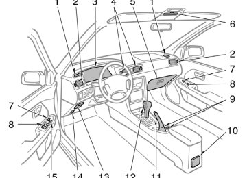
Instrument panel overview
1. Side defroster outlets 2. Side vents 3. Instrument cluster 4. Center vents 5. Glove box 6. Garage door opener box or
miscellaneous box
7. Power door lock switches 8. Power window switches 9. Cup holders 10. Cup holder or rear ashtray 11. Parking brake lever 12. Automatic transmission selector lever 13. Auxiliary box 14. Hood lock release lever 15. Window lock switch
1. Power rear view mirror control switch 2. Headlight and turn signal switch 3. Wiper and washer switches 4. Clock 5. Emergency flasher switch 6. Car audio 7. Rear window and outside rear view
mirror defoggers switch 8. Air conditioning controls 9. Front ashtray 10. Power outlet 11. Cigarette lighter 12. Ignition switch 13. Cruise control switch 14. Tilt steering lock release lever 15. Instrument panel light control knob
Instrument cluster overview
1. Engine coolant temperature gauge 2. Service reminder indicators and
indicator lights
3. Fuel gauge
4. Speedometer 5. Odometer and two trip meters 6. Tachometer
7. Trip meter reset knob 8. Low fuel level warning light
Indicator symbols on the instrument panel
Brake system warning light∗1
Low windshield washer fluid level warning light∗1
Seat belt reminder light∗1
Discharge warning light∗1
Malfunction indicator lamp∗1
Turn signal indicator lights
Headlight high beam indicator light
Overdrive−off indicator light
Low oil pressure warning light∗1
Cruise control indicator light∗2
Anti−lock brake system warning light∗1
Automatic transmission indicator lights
Open door warning light∗1
Rear light failure warning light∗1
SRS warning light∗1
∗1: For details, see “Service reminder indicators and warning
buzzers” in Chapter 1−5.
∗2: If this light flashes, see “Cruise control” in Chapter 1−6.
6
Part 1
OPERATION OF INSTRUMENTS AND CONTROLS—Keys
Chapter 1−2
Keys and DoorsD Keys D Side doors D Power windows D Trunk lid D Hood D Refueling
Your vehicle is supplied with two kinds of key. 1. Master key—This key works in every
lock.
2. Sub key—This key will not work in the
glove box and trunk.
To protect things locked in the glove box or trunk when you have your vehicle parked, leave the sub key with the atten- dant. Since lid can be locked without a key, you should always carry a spare master key in case you accidentally lock your keys inside the ve- hicle.
the doors and
trunk
KEY NUMBER PLATE Your key number is shown on the plate. Keep the plate in a safe place such as your wallet, not in the vehicle. If you should lose your keys or if you need additional keys, duplicates can be made by your authorized Toyota CNG dealer using the key number. We recommend you to write down the key number and keep it in safe place.
Side doors
LOCKING AND UNLOCKING WITH KEY Insert the key into the keyhole and turn it. To lock: Turn the key forward. To unlock: Turn the key backward. All lock and unlock simulta- neously with either front door. In the driv- er’s door lock, turning the key once will unlock the driver’s door and twice in suc- cession will unlock all the doors simulta- neously.
the doors
LOCKING AND UNLOCKING WITH INSIDE LOCK BUTTON Move the lock button. To lock: Push the knob forward. To unlock: Pull the knob backward. Closing the door with the lock knob in the lock position will also lock the door. Be careful not to lock your keys in the ve- hicle. The door cannot be locked if you leave the key in the ignition switch.
Driver’s side
Passenger’s side
LOCKING AND UNLOCKING WITH POWER DOOR LOCK SWITCH Push the switch. To lock: Push the switch on the front side. To unlock: Push the switch on the rear side. All the doors lock or unlock simultaneous- ly.
CAUTION
Before driving, be sure that the doors are closed and locked, especially when small children are in the ve- hicle. Along with the proper use of seat belts, locking the doors helps prevent the driver and passengers from being thrown out from the ve- hicle during an accident. It also helps prevent the doors from being opened unintentionally.
to
the
lock
lever
the “LOCK”
REAR DOOR CHILD−PROTECTORS Move position as shown on the label. This feature allows you to lock a rear door so it can be opened from the outside only, not from inside. We recommend us- ing this feature whenever small children are in the vehicle.
Power windows
Window lock switch
Automatic operation (to open only): Push the switch completely down and then release it. The window will fully open. To stop the window partway, lightly pull the switch up and then release it.
The windows can be operated with the switch on each door. The power windows work when the ignition switch is in the “ON” position. Key off operation: If both front doors are closed, they work for 45 seconds even after the ignition switch is turned off. They stop working when either is opened. OPERATING THE DRIVER’S WINDOW Use the switch on the driver’s door. Normal operation: The window moves as long as you hold the switch. To open: Lightly push down the switch. To close: Pull up the switch.
front door
10
THE
PASSENGERS’
OPERATING WINDOWS Use the switches on the passengers’ doors. The driver’s door also has switches that control the passengers’ windows. The window moves as long as you hold the switch. To open: Push down the switch. To close: Pull up the switch. If you push in the window lock switch on the driver’s door, the passengers’ windows cannot be operated.
CAUTION
To avoid serious personal injury, you must do the following. D Always make sure the head, hands and other parts of the body of all occupants are kept completely in- side the vehicle before you close the power windows. If someone’s neck, head or hands gets caught in a closing window, it could result in a serious injury. When anyone closes the power windows, be sure that they operate the windows safe- ly.
D When small children are in the ve- hicle, never let them use the power window switches without supervi- sion. Use the window lock switch to prevent from making unex- pected use of the switches.
them
D Never leave small children alone in the vehicle, especially with the igni- tion key still inserted. They could use the power window switches and in a window. Unat- get tended children can become in- volved in serious accidents.
trapped
Trunk lid—
“Luggage stowage precautions”
To open the trunk lid from the outside, insert the master key and turn it clock- wise. in See Part 2 for precautions to observe for load- ing luggage. To close the trunk lid, lower it and press down on it. After closing the trunk lid, try pulling it up to make sure it is securely closed.
11
—Lock release lever
—Luggage security system
CAUTION
Keep the trunk lid closed while driv- ing. This not only keeps the luggage from being thrown out but also pre- vents exhaust gases from entering the vehicle.
To open the trunk lid from the driver’s seat, pull up on the lock release lever.
This system deactivates the lock re- lease lever so that things locked in the trunk can be protected. After closing the trunk lid, insert the master key and turn it counterclockwise to deactivate the lock release lever. After closing the trunk lid, try pulling it up to make sure it is securely locked.
12
Hood
To open the hood: 1. Pull the hood lock release lever. The
hood will spring up slightly.
CAUTION
Before driving, be sure that the hood is closed and securely locked. Other- wise, the hood may open unexpected- ly while driving and an accident may occur.
2. In front of the vehicle, pull up the the
lever and
lift
auxiliary catch hood.
3. Hold the hood open by inserting the
support rod into the slot.
Before closing the hood, check to see that you have not forgotten any tools, rags, etc. and return its clip—this prevents rattles. Then lower the hood make sure it If necessary, press down gently on the front edge to lock it.
the support rod
into place.
locks
to
CAUTION
After inserting the support rod into the slot, make sure the rod supports the hood securely from falling down on to your head or body.
13
CAUTION
D In order to safety refuel and avoid serious personal the CNG station staff to refuel the ve- hicle with CNG for you.
injury, ask
D Do not start the engine while refuel- ing. As the natural gas is flam- mable, an explosion or a fire could occur. Also, do not smoke or allow open flames when refueling. D If you smell or hear fuel
leaking while refueling, immediately stop re- fueling. Do not refuel it until after the leak has been repaired.
—Refueling method (high speed refueling)
There are two ways of natural gas re- fueling: high and low speed. This manu- al explains typical high speed refueling. As for the low speed refueling method, follow the manufacturer for the refueling equipments. 1. To open the refueling plug door, pull
instructions provided by
the
the lever up. When refueling, turn off the engine.
that
meets
Refueling— —Refueling precaution When refueling, you must use a special nozzle ANSI/AGA NGV−1−1994 standards. There are three types of nozzles. Use a P36 type nozzle for this vehicle. If a P36 nozzle is not available at a nearby CNG station, you may use another type of nozzle, but you cannot expect to get a completely full tank with it. For your safety, ask and follow the in- structions at the refueling station when refueling. Before starting to refuel, wipe off mud or dirt that may be deposited around the fuel receptacle. You will hear a chattering noise from the tank when it is being filled, but this is quite normal. If you hear fuel leaking from the fuel re- ceptacle, stop refueling immediately and have your authorized Toyota CNG dealer check the fuel receptacle. For information on CNG stations, refer to the station “Refueling station information” on page iii in the beginning of this manu- al.
14
2. Remove the rubber cap. Check there is no mud or dirt around the fuel receptacle.
3. Fit the filling nozzle securely on the
fuel receptacle.
There are various types of filling nozzles so follow the instructions at each CNG station.
4. Turn the valve
lever to fasten the nozzle to the fuel receptacle and to start filling the tank.
15
5. Refueling will stop automatically when the tank is full. When discon- necting the filling nozzle, follow the instructions of the refueling station. Reverse the procedure to disconnect the nozzle after filling the tank. When disconnecting the filling nozzle, you may hear a brief hissing sound as a small amount of fuel escapes, but this is nor- mal.
16
Part 1
OPERATION OF INSTRUMENTS AND CONTROLS—Chapter 1−3
Seats, Seat belts, Steering wheel and MirrorsD Seats D Front seats D Head restraints D Seat belts D SRS driver and front passenger
airbags
D Child restraint D Tilt steering wheel D Outside rear view mirrors D Anti−glare inside rear view
mirror
D Sun visors
Seats While the vehicle is being driven, all ve- hicle occupants should have the seatback upright, sit well back in the seat and prop- erly wear the seat belts provided.
Front seats— —Seat adjustment precautions Adjust the driver’s seat so that the foot pedals, steering wheel and instrument panel controls are within easy reach of the driver.
CAUTION
CAUTION
D Do not drive the vehicle unless the occupants are properly seated. Do top of a not allow sitting on folded−down seatback, or the luggage compartment. Persons not properly seated and not properly re- strained by seat belts can be se- verely injured in the event of emer- gency braking or a collision.
in
D During driving, do not allow pas- to stand up or move sengers around between seats. Severe inju- ries can occur in the event of emer- gency braking or a collision.
D Adjustments should not be made while the vehicle is moving, as the seat may unexpectedly move and cause the driver to lose control of the vehicle.
D When adjusting the seat, be careful not to hit the seat against a pas- senger or luggage.
D After adjusting the seat position, try sliding it forward and backward to make sure it is locked in posi- tion.
D After adjusting the seatback, exert body pressure to make sure it is locked in position.
D Do not put objects under the seats. The objects may interfere with the seat−lock mechanism or unexpect- edly push up the seat position ad- justing lever; the seat may suddenly move, causing the driver to lose control of the vehicle.
17
—Adjusting front seats
D While adjusting the seat, do not put your hands under the seat or near the moving parts. You may catch and injure your hands or fingers.
18
1. SEAT POSITION ADJUSTING LEVER Pull the lever up. Then slide the seat to the desired position with slight body pressure and release the lever. 2. SEATBACK
ADJUSTING
ANGLE
LEVER
lever up. lean back to the desired angle
Lean forward and pull the Then and release the lever.
CAUTION
To reduce the risk of sliding under the lap belt during a collision, avoid reclining the seatback any more than needed. The seat belts provide maxi- mum protection in a frontal or rear collision when the driver and the pas- senger are sitting up straight and well back If you are reclined, the lap belt may slide past your hips and apply restraint forces directly to the abdomen. Therefore, in the event of a frontal collision, the risk of personal injury may increase with increasing recline of the seat- back.
in the seats.
3. SEAT CUSHION HEIGHT ADJUSTING
KNOB
Turn the knob either way.
Head restraints
Front
Rear