- 2012 Subaru Tribeca Owners Manuals
- Subaru Tribeca Owners Manuals
- 2008 Subaru Tribeca Owners Manuals
- Subaru Tribeca Owners Manuals
- 2007 Subaru Tribeca Owners Manuals
- Subaru Tribeca Owners Manuals
- 2006 Subaru Tribeca Owners Manuals
- Subaru Tribeca Owners Manuals
- 2010 Subaru Tribeca Owners Manuals
- Subaru Tribeca Owners Manuals
- 2011 Subaru Tribeca Owners Manuals
- Subaru Tribeca Owners Manuals
- 2009 Subaru Tribeca Owners Manuals
- Subaru Tribeca Owners Manuals
- Download PDF Manual
-
this indicates that its system has a problem. Contact your SUBARU dealer for repairs.
the same fuse blows again,
If
1) Good 2) Blown
inspect
If any lights, accessories or other electrical controls do not operate, the corresponding fuse. If a fuse has blown, replace it. 1. Turn the ignition switch to the “LOCK” position and turn off all electrical acces- sories. 2. Remove the cover. 3. Determine which fuse may be blown. The back side of each fuse box cover and the “Fuses and circuits” section in chapter 12 in this manual show the circuit for each fuse.
11-40 Maintenance and service
Installation of accessories
Always consult your SUBARU dealer before installing fog lights or any other electrical equipment in your vehicle. Such accessories may cause the electronic system to malfunction if they are incor- rectly installed or if they are not suited for the vehicle.
Replacing bulbs
Maintenance and service 11-41
– CONTINUED –
11-42 Maintenance and service
1) 2)
3) 4) 5) 6)
7) 8)
High beam headlight
Low beam headlight
Vehicle with HID light
Vehicle without HID light
Front turn signal/Parking light Parking/Front side marker light Map light Dome light
Vehicles with Rear Seat Entertainment Vehicles without Rear Seat Entertainment
Door step light
Vanity mirror light
Tail light
Fog light
9) 10) Cargo area light 11) 12) Brake/tail light 13) Rear turn signal light 14) Back-up light 15) Rear gate light 16)
License plate light
Wattage 12V-65W
Bulb No. HB3
12V-35W
12V-55W
12V-28/8W 12V-5W 12V-8W
12V-5W 12V-8W 12V-3W
12V-3W
12V-55W 12V-13W 12V-5W 12V-27/8W 12V-27W 12V-16W 12V-5W 12V-5W
D1S
H7
2357NA 168(W5W) –
–
–
–
H3
912
168
1157(W27/8W) 1156(W27W) 921
(W5W) 168(W5W)CAUTION
Replace any bulb only with a new bulb of the specified wattage. Using a bulb of different wattage could result in a fire.
& Headlights (Vehicles with HID
headlights)
WARNING
High-intensity-discharge (HID) bulbs are used for the low beams of the headlights. These HID bulbs use an extremely high voltage. To avoid the risk of an electric shock and result- ing serious injury, you should not attempt to replace them. Neither should you attempt to replace the high-beam bulbs, remove/refit the headlight assemblies, or remove any headlight-assembly compo- nents. For replacement of the head- light bulbs (low-beam and high- beam), removal and installation of the headlight assemblies, and re- moval of headlight-assembly com- ponents, contact your SUBARU dealer.
& Headlights (Vehicles without
HID headlights)
! Low beam light bulbs (right-hand
side)
2. Use a screwdriver to remove the bulb cover.
Maintenance and service 11-43
CAUTION
Halogen headlight bulbs become very hot while in use. If you touch the bulb surface with bare hands or greasy gloves, finger prints or grease on the bulb surface develop into hot spots, causing the bulb to break. If there are finger prints or grease on the bulb surface, wipe them away with a soft cloth mois- tened with alcohol.
NOTE . If headlight aiming is required, con- sult your SUBARU dealer for proper adjustment of the headlight aim. . It may be difficult to replace the bulbs. Have the bulbs replaced by your SUBARU dealer if necessary.
1. Use a screwdriver to undo the clips on the air intake duct, then remove the air intake duct.
3. Disconnect the electrical connector. 4. Remove the retainer spring. 5. Replace the bulb, then set the retainer spring securely. 6. Reconnect the electrical connector. 7. screws. 8.
Install the bulb cover with the fixing
Install the air intake duct with the clips.
NOTE Contact your SUBARU dealer for the bulb replacement of the left-hand side.
– CONTINUED –
11-44 Maintenance and service
! High beam light bulbs
2. Use a screwdriver to remove the secured clip of the washer tank. To make it easy to access the bulb, move the washer tank to the horizontal direction. (left-hand side)
place and secure it by clip. (left-hand side)
& Parking light (right-hand
side)
Right-hand side
1. Use a screwdriver to undo the clips on the air intake duct, then remove the air intake duct. (right-hand side)
Left-hand side
the electrical connector
3. Disconnect from the bulb. 4. Remove the bulb from the headlight assembly by turning it counterclockwise. 5. Replace the bulb with new one. At this time, use care not to touch the bulb surface. 6. Reconnect the electrical connector. 7. To install assembly, turn it clockwise until it clicks. 8. (right-hand side) 9. Set
the washer tank to the original
the air intake duct with clips.
the bulb to the headlight
Install
1. Remove the bulb socket from the headlight assembly by turning it counter- clockwise.
& Front turn signal light (right-
hand side)
2. Pull the bulb out of the socket. Install a new bulb. 3. Set the bulb socket into the headlight assembly and turn it clockwise until it locks.
NOTE Contact your SUBARU dealer for the bulb replacement of the left-hand side.
1. Remove the bulb socket from the headlight assembly by turning it counter- clockwise.
Maintenance and service 11-45
2. Remove the bulb from the socket by pushing it and turning counterclockwise. Install a new bulb. 3. Set the bulb socket into the headlight assembly and turn it clockwise until it locks.
NOTE Contact your SUBARU dealer for the bulb replacement of the left-hand side. & Front fog light It may be difficult to replace the bulbs. Have the bulbs replaced by your SUBARU dealer if necessary.
– CONTINUED –
11-46 Maintenance and service
& Rear combination lights
the rear combination lamp assembly rear- ward and remove it from the vehicle.
6. Reinstall the rear combination light assembly by sliding the two-pronged part of the combination light assembly securely to each holder of the vehicle side. 7. Tighten the two mounting screws, and then close the covers.
1. Remove the two covers by inserting the tip of a flat-head screwdriver.
1) Brake/tail light 2) Rear turn signal light
3. Remove the bulb holder from the rear combination light assembly by turning it counterclockwise. 4. Remove the bulb from the socket by pushing it and turning counterclockwise. Install a new bulb. 5. Set into the rear combination light assembly and turn it clockwise until it locks.
the bulb holder
2. Using a Phillips screwdriver, remove the upper and lower screws. Then, slide
& Back-up light/Tail light
2. Turn the bulb socket counterclockwise and remove it. 3. Pull the bulb out of the bulb socket and replace it with a new one. 4. clockwise. Install rear gate.
the bulb socket by turning it the light cover on the
Install
& Rear gate light
1. Use a flat-head screwdriver to remove the light cover from the rear gate trim.
Maintenance and service 11-47
2. Pull the bulb out of the bulb socket and replace it with a new one. 3. the rear gate.
Install the rear gate light assembly on
& License plate light
1. Use a flat-head screwdriver to remove the rear gate light assembly from the rear gate trim.
Tail light
1) 2) Back-up light
– CONTINUED –
11-48 Maintenance and service
1. Wrap a flat-head screwdriver in vinyl tape or cloth, insert it into the gap between the license plate light assembly and the rear gate. 2. Carefully pry the light assembly to remove it.
& Dome light
4. Pull the bulb out of the socket. Install a new bulb. 5. Set the bulb socket into the license plate light assembly and turn it clockwise until it locks. 6. Reinstall the license plate light assem- bly to the rear gate.
Vehicles with Rear Seat Entertainment
3. Remove the bulb socket from the license plate light assembly by turning it counterclockwise.
Vehicles without Rear Seat Entertainment 1. Remove the lens by prying the edge of the lens with a flat-head screwdriver.
& Map light
Maintenance and service 11-49
straight downward to remove it. 3. Install a new bulb. 4. Reinstall the lens.
& Vanity mirror light
2. Turn the bulb until the flat surfaces at its ends are aligned vertically. Pull the bulb straight downward to remove it. Install a new bulb. 3. Reinstall the lens.
1. Remove the lens by prying the edge of the lens with a flat-head screwdriver.
1. Remove the lens by prying the edge of the lens with a flat-head screwdriver.
2. Turn the bulb until the flat surfaces at its ends are aligned vertically. Pull the bulb
– CONTINUED –
11-50 Maintenance and service
& Cargo area light
3. Pull the bulb out of the socket. Install a new bulb. 4. Reinstall the lens to the cargo area light assembly. 5. Reinstall the cargo area light assembly to the roof trim.
2. Pull the bulb out of the socket. Install a new bulb. 3. Reinstall the lens.
& Door step light It may be difficult to replace the bulbs. Have the bulbs replaced by your SUBARU dealer if necessary.
1. Remove the cargo area light assembly by prying the edge of the light with a flat- head screwdriver. 2. Remove the lens from the cargo area light assembly.
Specifications
Specifications ................................................. Dimensions.................................................... Engine ........................................................... Electrical system............................................ Capacities ...................................................... Tires .............................................................. Wheel alignment ............................................
12-2
12-2
12-2
12-3
12-3
12-3
12-4Fuses and circuits .........................................
Fuse panel located in the passenger
compartment ................................................
Fuse panel located in the engine
compartment ................................................ Bulb chart....................................................... Vehicle identification .....................................
12-5
12-5
12-7
12-8
12-912
12-2 Specifications
Specifications
These specifications are subject to change without notice. & Dimensions
without roof rail
with roof rail
Front
Rear
Overall length
Overall width Overall height
Wheel base Tread
Ground clearance
& Engine
Engine model
Engine type
Displacement cc (cu-in) Bore 6 Stroke in (mm) Compression ratio
Firing order
in (mm)
191.5 (4,865)
73.9 (1,878)
66.4 (1,686)
67.7 (1,720)
108.2 (2,749)
62.2 (1,580)
62.1 (1,578)
8.4 (213)
EZ36D
(3.6-liter, DOHC, non-turbo)
Horizontally opposed, liquid cooled 6 cylinder, 4 stroke gasoline engine
3,630 (222)
3.62 6 3.58 (92.0 6 91.0)
10.5 : 1
1 – 6 – 3 – 2 – 5 – 4
& Electrical system
Battery type and capacity (5HR)
Alternator
Spark plugs
& Capacities
Fuel tank Engine oil
Transmission fluid
Front differential gear oil
Rear differential gear oil
Power steering fluid Engine coolant
& Tires
Tire size
Wheel size Pressure
Temporary spare tire
Front
Rear
Rear at trailer towing
Size
Pressure
75D23L (12V-52AH)
12V-130A
SILFR6A (NGK)
16.9 US gal (64 liters, 14.1 Imp gal)
6.7 US qt (6.3 liters, 5.5 Imp qt)
10.4 US qt (9.8 liters, 8.6 Imp qt)
1.5 US qt (1.4 liters, 1.2 Imp qt)
0.8 US qt (0.8 liter, 0.7 Imp qt)
0.9 US qt (0.9 liter, 0.8 Imp qt) 8.0 US qt (7.6 liters, 6.7 Imp qt)
P255/55R18 104H
18 6 8JJ
33 psi (230 kPa, 2.3 kgf/cm2) 32 psi (220 kPa, 2.2 kgf/cm2) 32 psi (220 kPa, 2.2 kgf/cm2)
T165/80R17
60 psi (420 kPa, 4.2 kgf/cm2)
Specifications 12-3
– CONTINUED –
12-4 Specifications
& Wheel alignment
Toe
Camber
Front
Rear
Front
Rear
0 in (0 mm)
0.0787 in (2 mm)
0800’ −0831’
Fuses and circuits & Fuse panel located in the passenger compartment
Fuse panel
10
11
12Fuse rating
20A Empty
15A 7.5A
7.5A 7.5A
15A
15A 20A
7.5A
7.5A 15A
Specifications 12-5
Circuit
Trailer hitch connector
rear
view mirrors
Integrated unit
Front wiper deicer relay
. Door locking . Moonroof . Combination meter . Remote control . Seat heater relay . Combination meter . Stop light . Mirror heater . Power supply (Battery) . Automatic transmission . SRS airbag . Engine control unit
Front wiper deicer
Turn signal unit
Integrated unit
system
(Sub)
unit
– CONTINUED –
12-6 Specifications
Fuse panel
Fuse rating
Circuit
Fuse panel
Fuse rating
Circuit
13
1415
16
17
18
19
20
21
2223
24
25
26
27
20A 15A
Empty
10A
15A
10A
7.5A
Empty
7.5A 15A
15A
15A
15A
7.5A
15A
Fog light
Front wiper
. Rear blower fan . Auto air conditioner unit . Headlight left side relay . Vehicle dynamics con-
Integrated unit
trol unit
28
29
30
3132
33
15A
15A
30A 7.5A
7.5A
7.5A
. Cargo socket . Position light . Rear combination light
Tail light
Illumination
. Seat heaters . Back-up light . Headlight right side re-
lay
. Starter relay . Air conditioner . Rear window defogger
relay coil
. Rear wiper . Rear window washer . Audio unit . SRS airbag
system
(Main)
. Power window relay . Rear blower fan
& Fuse panel located in the engine compartment
Specifications 12-7
Fuse panel
Fuse rating
Circuit
10
11
12
13
30A
20A
15A
15A
20A
15A
25A
15A
15A
. Vehicle dynamics control
unit
. Console socket . Headlight (right side) . Headlight (left side) . Backup . Horn . Rear window defogger Fuel pump . Automatic control unit
transmission
7.5A . Engine control unit
15A
Turn and hazard warning flasher
. Parking switch
20A 7.5A . Alternator
12-8 Specifications
Bulb chart
Description High beam headlight
Low beam headlight
Vehicles with HID light
Vehicles without HID light
Fog light Front turn signal/Parking light Parking/Front side marker light Rear combination light
Rear turn signal light Brake/tail
Tail light Back-up light License plate light Cargo area light Dome light
Wattage 12V-65W
12V-35W
12V-55W
12V-55W 12V-28/8W 12V-5W
12V-27W 12V-27/8W 12V-5W 12V-16W 12V-5W 12V-13W
12V-5W Vehicles with Rear Seat Entertainment Vehicles without Rear Seat Entertainment 12V-8W 12V-8W 12V-3W 12V-3W 12V-5W
Map light Vanity mirror light Door step light Rear gate light
Bulb No. HB3
D1S
H7
H3
2357NA 168(W5W)1156(W27W) 1157(W27/8W) 168
921
168(W5W) 912–
–
–
–
–
(W5W)
Vehicle identification
Specifications 12-9
Tire inflation pressure label
1) Vehicle identification number 2) Certification and bar code label 3) 4) Vehicle identification number plate 5) Model number plate 6) Emission control label 7)
Fuel label
— — — — — — — — — — — — — — — — — — — — — — — — — — — — — — — — — — — — — — — —
— — — — — — — — — — — — — — — — — — — — — — — — — — — — — — — — — — — — — — — —
— — — — — — — — — — — — — — — — — — — — — — — — — — — — — — — — — — — — — — — —
— — — — — — — — — — — — — — — — — — — — — — — — — — — — — — — — — — — — — — — —
— — — — — — — — — — — — — — — — — — — — — — — — — — — — — — — — — — — — — — — —
— — — — — — — — — — — — — — — — — — — — — — — — — — — — — — — — — — — — — — — —
— — — — — — — — — — — — — — — — — — — — — — — — — — — — — — — — — — — — — — — —
— — — — — — — — — — — — — — — — — — — — — — — — — — — — — — — — — — — — — — — —
— — — — — — — — — — — — — — — — — — — — — — — — — — — — — — — — — — — — — — — —
— — — — — — — — — — — — — — — — — — — — — — — — — — — — — — — — — — — — — — — —
— — — — — — — — — — — — — — — — — — — — — — — — — — — — — — — — — — — — — — — —
— — — — — — — — — — — — — — — — — — — — — — — — — — — — — — — — — — — — — — — —
— — — — — — — — — — — — — — — — — — — — — — — — — — — — — — — — — — — — — — — —
Consumer information and Reporting safety defects
For U.S.A. ....................................................... Tire information.............................................. Tire labeling ................................................... Recommended tire inflation pressure.............. Glossary of tire terminology ........................... Tire care – maintenance and safety practices...................................................... Vehicle load limit – how to determine..............
13-2
13-2
13-2
13-5
13-613-7
13-8Determining compatibility of tire and vehicle load
capacities ...................................................
Adverse safety consequences of overloading on
handling and stopping and on tires ............. Steps for Determining Correct Load Limit...... Uniform tire quality grading standards ....... Treadwear .................................................... Traction AA, A, B, C...................................... Temperature A, B, C...................................... Reporting safety defects (U.S.A.) ................
13-11
13-11
13-11
13-12
13-12
13-12
13-13
13-1413
13-2 Consumer information and Reporting safety defects
For U.S.A.
The following information has been compiled according to Code of Federal Regulations “Title 49, Part 575”.
Tire information & Tire labeling Many markings (e.g. Tire size, Tire Identification Number or TIN) are placed on the sidewall of a tire by tire manufacturers. These markings can provide you with useful infor- mation on the tire. ! Tire size Your vehicle comes equipped with P-Metric tire size. It is important to understand the sizing system in selecting the proper tire for your vehicle. Here is a brief review of the tire sizing system with a breakdown of its individual elements. ! P Metric With the P-Metric system, Section Width is measured in millimeters. To convert millimeters into inches, divide by 25.4. The Aspect Ratio (Section Height divided by Section Width) helps provide more dimen- sional the tire size.
information about
Example:
(1) P = Certain tire type used on light duty vehicles such as passen- ger cars (2) Section Width in millimeters (3) Aspect Ratio (= section height 7 section width). (4) R = Radial Construction (5) Rim diameter in inches ! Load and Speed Rating Descrip-
tions
The load and speed rating descrip- tions will appear following the size designation. facts They provide two important about the number designation is its load index. Sec- ond, the letter designation indicates the tire’s speed rating.
the tire. First,
Example:
(210 km/h).
individual elements.
Consumer information and Reporting safety defects 13-3
(6) Load Index: A numerical code which specifies the maximum load a tire can carry at the speed indicated by its speed symbol, at maximum inflation pressure. For example, “104” means 1,984
lbs (900 kg), “100” means 1,764 lbs (800 kg), “90” means 1,323 lbs (600
kg).WARNING
Load indices apply only to the tire, not to the vehicle. Putting a load rated tire on any vehicle does not mean the vehicle can be loaded up to the tire’s rated load.
(7) Speed Rating: An alphabetical system describing a tire’s capability to travel at established and prede- termined speeds. For example, “H” means 130 mph
WARNING
. Speed ratings apply only to the tire, not to the vehicle. Putting a speed rated tire on any vehicle does not mean the vehicle can be operated at the tire’s rated speed.
. The speed rating is void if the tires are worn out, da- maged, repaired, retreaded, or otherwise altered from If their original condition. tires are repaired, re- treaded, or otherwise al- tered, they may not be sui- table for original equipment tire designed loads and speeds.
! Tire Identification Number (TIN) Tire Identification Number (TIN) is marked on the intended outboard sidewall. The TIN is composed of four groups. Here is a brief review of the TIN with a breakdown of its
(1) Manufacturer’s Identification Mark (2) Tire Size (3) Tire Type Code (4) Date of Manufacture The first two figures identify the week, starting with “01” to represent the first full week of the calendar year; the second two figures repre- sent the year. For example, 0101
means the 1st week of 2001. ! Other markings The following makings are also placed on the sidewall. ! Maximum permissible inflationpressure
The maximum cold inflation pres- sure to which this tire may be “300 kPa inflated. For example, (44 PSI) MAX. PRESS”.
– CONTINUED –
13-4 Consumer information and Reporting safety defects
STEEL + 2 POLYESTER + 1
NYLON SIDEWALL 2 POLYE- STER” ! Uniform Tire Quality Grading(UTQG) For details, quality grading standards” chapter.
refer
to “Uniform tire in this
! Maximum load rating The load rating at the maximum permissible weight load for this tire. For example, “MAX. LOAD 730 kg (1609 LBS) @ 300 kPa (44 PSI) MAX. PRESS.”
WARNING
Maximum load rating applies only to the tire, not to the vehicle. Putting a load rated tire on any vehicle does not mean the vehicle can be loaded up to the tire’s rated load.
! Construction type Applicable construction of this tire. For example, “TUBELESS STEEL BELTED RADIAL” ! Construction The generic name of each cord material used in the plies (both sidewall and tread area) of this tire. “PLIES: TREAD 2
For example,Consumer information and Reporting safety defects 13-5
& Recommended tire inflation pressure ! Recommended cold tire inflation pressure Recommended cold tire inflation pressure for your vehicle’s tires is as follows,
Tire size Wheel size Pressure
Temporary spare tire
Front Rear Rear at trailer towing Size Pressure
P255/55R18 104H
18 6 8 JJ
33 psi (230 kPa, 2.3 kgf/cm2) 32 psi (220 kPa, 2.2 kgf/cm2) 32 psi (220 kPa, 2.2 kgf/cm2)
T165/80R17
60 psi (420 kPa, 4.2 kgf/cm2)
– CONTINUED –
13-6 Consumer information and Reporting safety defects
! Vehicle placard
The vehicle placard is affixed to the driver’s side B-pillar. Example:
The vehicle placard shows original tire size, recommended cold tire inflation pressure on each tire at maximum loaded vehicle weight, seating capacity and loading infor- mation. ! Adverse safety consequences
of under-inflation
Driving at high speeds with exces- sively low tire pressures can cause the tires to flex severely and to rapidly become hot. A sharp in- crease in temperature could cause tread separation, and failure of the tire(s). Possible resulting loss of vehicle control could lead to an accident. ! Measuring and adjusting air
pressure to achieve proper in- flation
Check and, if necessary, adjust the pressure of each tire (including the spare) at least once a month and before any long journey. Check the tire pressures when the tires are cold. Use a pressure gauge to adjust the tire pressures to the
specific values. Driving even a short distance warms up the tires and increases the tire pressures. Also, the tire pressures are affected by the outside temperature. is best to check tire pressure out- doors before driving the vehicle. When a tire becomes warm, the air inside it expands, causing the tire pressure to increase. Be careful not to mistakenly release air from a warm tire to reduce its pressure.
It
& Glossary of tire terminology . Cold tire pressure The pressure in a tire that has been driven less than 1 mile or has been standing for three hours or more. . Maximum inflation pressure The maximum cold inflation pres- sure to which a tire may be inflated. . Recommended inflation pres- sure The cold inflation pressure recom- mended by a vehicle manufacturer. . Intended outboard sidewall
(1) The sidewall that contains a
Consumer information and Reporting safety defects 13-7
whitewall, bears white lettering or bears manufacturer, brand, and/or model name molding that is higher or deeper than the same molding on the other side- wall of the tire, or (2) The outward facing sidewall of an asymmetrical tire that has a particular side that must al- ways face outward when mount- ing on a vehicle. . Accessory weight The combined weight (in excess of those standard items which may be replaced) of leather seats and cross bars to the extent that these items are available as f a c t o r y - i n s t a l l e d e q u i p m e n t (whether installed or not). . Curb weight The weight of a motor vehicle with standard equipment including the maximum capacity of fuel, oil, and coolant and air conditioning. . Maximum loaded vehicle weight The sum of curb weight, accessory weight, vehicle capacity weight and
floor mats,
production options weight. . Normal occupant weight 150 lbs (68 kg) times the number of occupants (3 occupants). . Occupant distribution Distribution of occupants in a vehi- cle, 2 in front, 1 in rear seat. . Production options weight The combined weight of those installed regular production options weighing over 5.1 lbs (2.3 kg) in excess of those standards items which they replace, not previously considered in curb weight or acces- sory weight. . Vehicle capacity weight The total weight of cargo, luggage and occupants that can be added to the vehicle. . Vehicle maximum load on a tire Load on an individual tire that is determined by distributing to each axle its share of the maximum loaded vehicle weight and dividing by two. . Vehicle normal load on a tire Load on an individual
tire that is
determined by distributing to each axle its share of the curb weight, accessory weight, and normal oc- cupant weight and dividing by two. & Tire care – maintenance and
safety practices
. Check on a daily basis that the tires are free from serious damage, nails, and stones. At the same time, check the tires for abnormal wear. . Inspect the tire tread regularly and replace the tires before their tread wear indicators become visi- ble. When a tire’s tread wear indicator becomes visible, the tire is worn beyond the acceptable limit and must be replaced immediately. With a tire in this condition, driving at even low speeds in wet weather can cause the vehicle to hydro- plane. Possible resulting loss of vehicle control can lead to an accident. . To maximize the life of each tire and ensure that the tires wear to rotate the uniformly,
is best
it
– CONTINUED –
13-8 Consumer information and Reporting safety defects
tires every 7,500 miles (12,000 km). Rotating the tires involves switch- ing the front and rear tires on the right-hand side of the vehicle and similarly switching the front and rear tires on the left-hand side of the vehicle. (Each tire must be kept on its original side of the vehicle.) Replace any damaged or unevenly the time of rotation. worn tire at After tire rotation, adjust the tire pressures and make sure the wheel nuts are correctly tightened. A tightening torque specification and a tightening sequence specification for the wheel nuts can be found “Flat tires” in chapter 9. & Vehicle load limit – how to
determine
The load capacity of your vehicle is determined by weight, not by avail- able cargo space. The load limit of your vehicle is shown on the vehicle placard attached to the driver’s side B-pillar. Locate the “The combined weight statement
of occupants and cargo should never exceed XXX kg or XXX lbs” on your vehicle’s placard. The vehicle placard also shows seating capacity of your vehicle. The total load capacity includes the total weight of driver and all pas- sengers and their belongings, any cargo, any optional equipment such as a trailer hitch, roof rack or bike carrier, etc., and the tongue load of a trailer. Therefore cargo capacity can be calculated by the following method. Cargo capacity = Load limit − (total weight of occupants + total weight of optional equipment + tongue load of a trailer (if applicable))
For towing capacity information and weight limits, refer to “Trailer towing” section in chapter 8. ! Calculating total and load ca- pacities varying seating con- figurations
Calculate the available load capa- city as shown in the following
examples:
Example 1A
Vehicle capacity weight of the vehicle is 1,157 lbs (525 kg), which is indicated on the vehicle placard with the statement “The combined weight of occupants and cargo should never exceed 525 kg or 1,157 lbs”. For example, if the vehicle has one occupant weighing 154 lbs (70 kg) plus cargo weighing 882 lbs (400
kg). 1. Calculate the total weight.Consumer information and Reporting safety defects 13-9
Example 1B
2. Calculate the available load ca- pacity.
2. Calculate the available load ca- pacity by subtracting the total weight from the vehicle capacity weight of 1,157 lbs (525 kg).
3. The result of step 2 shows that a further 121 lbs (55 kg) of cargo can be carried.
3. The total weight now exceeds the capacity weight by 55 lbs (25
kg), so the cargo weight must be reduced by 55 lbs (25 kg) or more.Example 2A
For example, if a person weighing 176 lbs (80 kg) now enters the same vehicle (bringing the number of occupants to two), the calcula- tions are as follows: 1. Calculate the total weight.
Vehicle capacity weight of
the
– CONTINUED –
13-10 Consumer information and Reporting safety defects
vehicle is 1,157 lbs (525 kg), which is indicated on the vehicle placard with the statement “The combined weight of occupants and cargo should never exceed 525 kg or 1,157 lbs”. For example, the vehicle has one occupant weighing 165 lbs (75 kg) plus cargo weighing 705 lbs (320
kg). In addition, the vehicle is fitted with a trailer hitch weighing 22 lbs (10 kg), to which is attached a trailer weighing 1,764 lbs (800 kg). 10% of the trailer weight is applied to the trailer tongue (i.e. Tongue load = 176 lbs (80 kg)). 1. Calculate the total weight.2. Calculate the available load ca- pacity.
40 lbs (18 kg) now enter the same vehicle (bringing the number of occupants to three), and a child restraint system weighing 11 lbs (5
kg) is installed in the vehicle for the child to use, the calculations are as follows: 1. Calculate the total weight.3. The result of step 2 shows that a further 88 lbs (40 kg) of cargo can be carried.
Example 2B
2. Calculate the available load ca- pacity.
For example, if a person weighing 143 lbs (65 kg) and a child weighing
Consumer information and Reporting safety defects 13-11
Weight Rating (GVWR). And each axle’s maximum loaded capacity is referred to Gross Axle Weight Rat- ing (GAWR). The GVWR and each axle’s GAWR are shown on the vehicle certification label affixed to the driver’s door. The GVWR and front and rear GAWRs are determined by not only the maximum load rating of tires but also loaded capacities of the vehi- cle’s suspension, axles and other parts of the body. Therefore, the vehicle cannot necessarily be loaded up to the tire’s maximum load rating on the tire sidewall.
this means that
& Adverse safety conse-
quences of overloading on handling and stopping and on tires
Overloading could affect vehicle handling, stopping distance, vehicle and tire as shown in the following. This could lead to an accident and possibly result in severe personal
injury. . Vehicle stability will deteriorate. . Heavy and/or high-mounted loads could increase the risk of rollover. . Stopping distance will increase. . Brakes could overheat and fail. . Suspension, bearings, axles and other parts of the body could break or experience accelerated wear that will shorten vehicle life. . Tires could fail. . Tread separation could occur. . Tire could separate from its rim. & Steps for Determining Cor-
rect Load Limit
1. Locate the statement “The com- bined weight of occupants and cargo should never exceed XXX pounds” on your vehicle’s placard. 2. Determine the combined weight of the driver and passengers that will be riding in your vehicle. 3. Subtract the combined weight of the driver and passengers from XXX kilograms or XXX pounds.
– CONTINUED –
3. The total weight now exceeds the capacity weight by 105 lbs (48
kg), so the cargo weight must be reduced by 105 lbs (48 kg) or more.& Determining compatibility of tire and vehicle load capaci- ties
four tires’ maximum The sum of load ratings must exceed the max- imum loaded vehicle weight (“GVWR”). In addition, sum of the maximum load ratings of two front tires and of tires must exceed each axle’s maximum loaded capacity (“GAWR”). Original equipment tires are designed to fulfill those conditions. The maximum loaded vehicle weight is referred to Gross Vehicle
two rear
13-12 Consumer information and Reporting safety defects
if
4. The resulting figure equals the available amount of cargo and luggage load capacity. For exam- the “XXX” amount equals ple, 1,400 lbs (635 kg) and there will be five- 150 lbs (68 kg) passengers in your vehicle, the amount of avail- able cargo and luggage load capa- city is 650 lbs. (1,400 − 750 (5 6
150) = 650 lbs). 5. Determine the combined weight of luggage and cargo being loaded on the vehicle. That weight may not safely exceed the available cargo and luggage load capacity calcu- lated in Step 4. If your vehicle will be towing a 6. trailer, load from your trailer will be transferred to your vehicle. Consult this manual to determine how this reduces the available cargo and luggage load capacity of your ve- hicle.Uniform tire quality grading standards
form to Federal Safety Require- ments in addition to these grades.
This information indicates the rela- tive performance of passenger car tires in the area of treadwear, traction, and temperature resis- tance. This is to aid the consumer in making an informed choice in the purchase of tires. Quality grades can be found where applicable on the tire sidewall be- tween tread shoulder and maxi- mum section width. For example:
Treadwear 200 Traction AA Tem- perature A
The quality grades apply to new pneumatic tires for use on passen- ger cars. However, they do not apply to deep tread, winter type snow tires, space-saver or tempor- ary use spare tires, tires with nominal rim diameters of 12 inches or less, or to some limited produc- tion tires.
All passenger car tires must con-
& Treadwear The treadwear grade is a compara- tive rating based on the wear rate of the tire when tested under con- trolled conditions on a specified government test course. For example, a tire graded 150
would wear one and one-half (1-1/ 2) times as well on the government course as a tire graded 100. The relative performance of tires de- pends upon the actual conditions of their use, however, and may depart significantly from the norm due to variations in driving habits, service practices and differences in road characteristics and climate.& Traction AA, A, B, C The traction grades, from highest to lowest, are AA, A, B and C. Those grades represent the tire’s ability to stop on wet pavement as measured under controlled conditions on spe-
Consumer information and Reporting safety defects 13-13
tires must meet under
grade C corresponds to a level of performance which all passenger car the Federal Motor Vehicle Safety Stan- dards No. 109. Grades B and A represent higher levels of perfor- mance on the laboratory test wheel than the minimum required by law.
WARNING
The temperature grade for this tire is established for a tire that is properly inflated and not overloaded. Excessive speed, underinflation, or ex- cessive loading, either sepa- rately or in combination, can cause heat buildup and possi- ble tire failure.
cified government test surfaces of asphalt and concrete. A tire marked C may have poor traction perfor- mance.
WARNING
The traction grade assigned to this tire is based on straight- ahead braking traction tests, and does not include accel- eration, cornering, hydroplan- ing, or peak traction charac- teristics.
& Temperature A, B, C The temperature grades are A (the highest), B, and C, representing the tire’s resistance to the generation of heat and its ability to dissipate heat when tested under controlled con- ditions on a specified indoor labora- tory test wheel. Sustained high temperature can cause the material of the tire to degenerate and reduce tire life, and excessive temperature can lead to sudden tire failure. The
13-14 Consumer information and Reporting safety defects
DC 20590. You can also obtain other information about motor ve- hicle safety from http://www.safercar.gov.
Reporting safety defects (U.S.A.)
If you believe that your vehicle has a defect which could cause a crash or could cause injury or death, you should immediately in- form the National Highway Traffic Safety Administration (NHTSA) in addition to notifying Subaru of America, Inc. If NHTSA receives similar com- plaints, it may open an investiga- tion, and if it finds that a safety defect exists in a group of vehi- cles, it may order a recall and remedy campaign. However, NHTSA cannot become involved in individual problems between you, your dealer, or Subaru of America, Inc. To contact NHTSA, you may call the Vehicle Safety Hotline toll-free at 1-888-327-4236
(TTY: 1-800-424-9153); go to http://www.safercar.gov; or write to: Administrator, NHTSA, 400
Seventh Street, SW., Washington,Index
14
14-2 Index
ABS (Anti-lock Brake System) ..................................... 7-20
Warning light ................................................. 3-15, 7-21
Accessories....................................................... 5-4, 11-40
Accessory power outlet................................................ 6-9
Active head restraint.................................................... 1-5
Air cleaner element .................................................. 11-14
Air filtration system..................................................... 4-11
Air flow ...................................................................... 4-2
Air flow mode selection................................................ 4-3
Alarm system ............................................................ 2-15
All-Wheel Drive warning light ....................................... 3-18
Aluminum wheel cleaning............................................ 10-3
Aluminum wheels..................................................... 11-30
Antenna system.......................................................... 5-2
Anti-lock Brake System (ABS) ..................................... 7-20
Arming the system ..................................................... 2-15
Armrest..................................................................... 1-12
AT OIL TEMPerature warning light ............................... 3-13
Audio control button ................................................... 5-27
Audio input terminal ................................................... 5-29
Audio set ................................................................... 5-4
Auto-dimming mirror/compass...................................... 3-38
Automatic climate control system .................................. 4-5
Automatic transmission ............................................... 7-12
Capacities............................................................. 12-3
Fluid................................................................... 11-15
MANUAL mode ..................................................... 7-15
Selector lever ........................................................ 7-13
Shift lock release ................................................... 7-17
Temperature warning light (AT OIL TEMP)................. 3-13Automatic/Emergency Locking Retractor (A/ELR) .......... 1-17
Battery .................................................................... 11-37
Jump starting ........................................................ 9-11
Replacement (Remote keyless entry system) .............. 2-7
Booster seat ............................................................. 1-36
BrakeAssist................................................................... 7-19
Booster ....................................................... 7-19, 11-21
Fluid ................................................................... 11-20
Pad and lining...................................................... 11-22
Parking ....................................................... 7-29, 11-23
Pedal .................................................................. 11-21
System................................................................. 7-19Brake pedal
Free play............................................................. 11-21
Reserve distance.................................................. 11-22
Brake system............................................................ 7-19
Warning light......................................................... 3-16
Braking .................................................................... 7-18
Tips ..................................................................... 7-18
Breaking-in of new brake pads and linings................... 11-22
BulbChart ................................................................... 12-8
Replacing ............................................................ 11-41Capacities ................................................................ 12-3
Cargo areaCover................................................................... 6-13
Light...................................................................... 6-2
Tie-down hooks ..................................................... 6-15
Catalytic converter ...................................................... 8-3
CenterConsole ................................................................. 6-6
Ventilators .............................................................. 4-4Changing
Flat tire .................................................................. 9-6
Oil and oil filter ...................................................... 11-8
Charge warning light .................................................. 3-13
CHECK ENGINE warning light/Malfunctionindicator lamp......................................................... 3-12
Checking
Brake pedal free play ........................................... 11-21
Brake pedal reserve distance ................................ 11-22
Engine oil level ...................................................... 11-7
Fluid level ........................................ 11-15, 11-19, 11-20
Gear oil level ....................................................... 11-18
Child restraint systems ............................................... 1-30
Installation with A/ELR seatbelt................................ 1-33
Lower and tether anchorages .................................. 1-37
Child safety ................................................................... 5
Locks ................................................................... 2-19Chime
Key ....................................................................... 3-4
Seatbelt ........................................................ 1-17, 3-10
Chrome plated wheels .............................................. 11-31
CleaningAluminum wheels................................................... 10-3
Interior.................................................................. 10-5
Ventilation grille ..................................................... 4-10Index 14-3
Climate control system
Automatic ............................................................... 4-5
Clock ....................................................................... 3-21
Coolant ................................................................... 11-11
Cooling system ........................................................ 11-11
Corrosion protection........................................... 8-10, 10-4
Cruise control ........................................................... 7-30
Set indicator light................................................... 3-21
Cruise control indicator light........................................ 3-20
Cup holder ................................................................. 6-7
Front passenger’s.................................................... 6-8Daytime running light system ...................................... 3-27
Differential gear oilFront................................................................... 11-17
Rear ................................................................... 11-18
Dimensions............................................................... 12-2
Disarming the system ................................................ 2-17
Disc brake pad wear warning indicators ....................... 7-19
Dome light ........................................................ 6-2, 11-48
DoorLocks..................................................................... 2-4
Open warning light................................................. 3-17
Drive belts ............................................................... 11-15
DrivingAll-Wheel Drive vehicle .......................................... 3-18
Car phone/cell phone.................................................. 7
Drinking..................................................................... 6
Drugs........................................................................ 6
Foreign countries..................................................... 8-414-4 Index
Pets ......................................................................... 7
Snowy and icy roads ............................................... 8-9
Tips....................................................................... 8-4
Tired or sleepy........................................................... 7Electrical system........................................................ 12-3
Electronic Brake Force Distribution(EBD) system ................................................. 3-17, 7-22
Emergency Locking Retractor (ELR)............................. 1-17
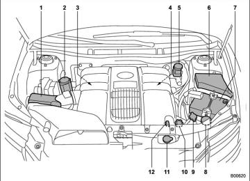
EngineCompartment overview ........................................... 11-6
Coolant............................................................... 11-11
Exhaust gas (Carbon monoxide) ............................ 5, 8-2
Hood .................................................................... 11-4
Oil........................................................................ 11-7
Overheating .......................................................... 9-14
Starting.................................................................. 7-7
Stopping ................................................................ 7-8
Exterior care.............................................................. 10-2Flat tires .................................................................... 9-6
Floor mat .................................................................. 6-12
Fluid levelAutomatic transmission ........................................ 11-15
Brake ................................................................. 11-20
Power steering .................................................... 11-19
Fog light switch.......................................................... 3-32
Folding mirror switch .................................................. 3-41Front
Differential gear oil................................................ 11-17
Fog light.............................................................. 11-45
Seatbelt pretensioners ........................................... 1-27
Seats ..................................................................... 1-2
Turn signal light.................................................... 11-45Front seats
Fore and aft adjustment ........................................... 1-3
Reclining ................................................................ 1-3
Fuel ........................................................................... 7-2
Economy hints ........................................................ 8-2
Filler lid and cap...................................................... 7-3
Gauge.................................................................... 3-8
Requirements ......................................................... 7-2
Fuses ..................................................................... 11-38
Fuses and circuits ..................................................... 12-5GAWR (Gross Axle Weight Rating).............................. 8-12
Glove box................................................................... 6-5
GVWR (Gross Vehicle Weight Rating).......................... 8-12Hazard warning flasher .......................................... 3-5, 9-2
Head restraint adjustment............................................. 1-5
Rear .................................................................... 1-11Headlight
Beam leveler......................................................... 3-29
Flasher................................................................. 3-27
Indicator light ........................................................ 3-21
Headlights ....................................................... 3-26, 11-42High beam indicator light ............................................ 3-20
High/low beam change (dimmer).................................. 3-27
Horn......................................................................... 3-42
Hose and connections .............................................. 11-11Ignition switch............................................................. 3-3
Light...................................................................... 3-4
Illuminated entry ......................................................... 2-9
Illumination brightness control...................................... 3-28
Immobilizer................................................................. 2-3
Indicator light.......................................................... 2-4Immobilizer system
Indicator light......................................................... 3-19
Indicator light
Cruise control ........................................................ 3-20
Cruise control set................................................... 3-21
Front fog............................................................... 3-21
Headlight .............................................................. 3-21
High beam ............................................................ 3-20
Security ................................................................ 3-19
Selector lever/Gear position .................................... 3-20
SPORT mode........................................................ 3-20
Traction Control system OFF................................... 3-18
Turn signal ............................................................ 3-20
Vehicle Dynamics Control operation ......................... 3-18Indicator lights
Vehicle Dynamics Control ............................... 7-25, 7-25
Inside mirror .............................................................. 3-38
Interior light ................................................................ 6-2Index 14-5
Jack and jack handle ................................................. 9-19
Jump starting ............................................................ 9-11Key
Keyless entry system ............................................... 2-7
Number .................................................................. 2-2
Reminder chime ...................................................... 3-4
Replacement........................................................... 2-4
Keys .......................................................................... 2-2Leather seat materials................................................ 10-5
LightCargo area ............................................................. 6-2
Control switch ....................................................... 3-26
Dome..................................................................... 6-2
Map ....................................................................... 6-3
Rear gate ............................................................... 6-3
Loading your vehicle.................................................. 8-11
Low fuel warning light .......................................... 3-8, 3-17
Low tire pressure warning light.................................... 3-14
Lower and tether anchorage ....................................... 1-37
Lumbar support ........................................................... 1-6Main fuse ................................................................ 11-39
MaintenancePrecautions .......................................................... 11-3
Schedule .............................................................. 11-314-6 Index
Seatbelt ................................................................ 1-27
Tools .................................................................... 9-19
Malfunction indicator lamp........................................... 3-12
Map light........................................................... 6-3, 11-49
Maximum load limits................................................... 8-20
Meters and gauges ..................................................... 3-5
Mirrors...................................................................... 3-38
Moonroof .................................................................. 2-23
Multi function display .................................................. 3-23New vehicle break-in driving......................................... 8-2
Odometer................................................................... 3-6
Oil filter..................................................................... 11-8
Oil levelEngine.................................................................. 11-7
Front differential gear ........................................... 11-17
Rear differential ................................................... 11-18
Oil pressure warning light............................................ 3-13
On-pavement and off road driving ................................. 8-5
Outside mirrors .......................................................... 3-39
Outside temperature indication..................................... 3-22
Overhead console....................................................... 6-7
Overheating engine .................................................... 9-14Parking
Brake ................................................................... 7-29
Brake stroke........................................................ 11-23Light switch .......................................................... 3-32
Tips ..................................................................... 7-29
Parking your vehicle .................................................. 7-29
Periodic inspections ..................................................... 8-4
PowerDoor locking switch.................................................. 2-6
Outside mirrors ..................................................... 3-41
Seat....................................................................... 1-3
Steering ............................................................... 7-18
Steering fluid........................................................ 11-19
Windows .............................................................. 2-19
Precautions against vehicle modification............... 1-30, 1-69
Preparing to drive ........................................................ 7-7
Printed antenna........................................................... 5-2Rear
Air conditioner......................................................... 4-8
Combination lights ................................................ 11-46
Gate ............................................................ 2-22, 9-18
Gate light ............................................................... 6-3
Seats ..................................................................... 1-7Rear differential
Gear oil ............................................................... 11-18
Oil temperature warning light .................................. 3-14Rear seat
Folding down .......................................................... 1-9
Rear view camera ..................................................... 6-21
Rear windowDefogger button .................................................... 3-37
Wiper and washer switch........................................ 3-35Index 14-7
Wiper blades ....................................................... 11-35
Roof rail and crossbar................................................ 8-13
Recommended
Automatic transmission fluid .................................. 11-16
Brake fluid........................................................... 11-21
OIL grade and viscosity ............. 11-9, 11-10, 11-17, 11-18
Power steering fluid.............................................. 11-20
Spark plugs......................................................... 11-15
Remote engine start system ......................................... 7-8
Remote keyless entry system ....................................... 2-7
ReplacementBrake pad and lining ............................................ 11-22
Wiper blades ....................................................... 11-33Replacing
Air cleaner element .............................................. 11-14
Battery (remote keyless entry system) ....................... 2-7
Lost transmitters (keyless entry system).................... 2-11
Replacing bulbs ....................................................... 11-41
Backup light/Tail light ............................................ 11-47
Cargo area light ................................................... 11-50
Clearance light .................................................... 11-44
Dome light .......................................................... 11-48
Door step light ..................................................... 11-50
Front fog light ...................................................... 11-45
Front turn signal light............................................ 11-45
Headlight ............................................................ 11-42
License plate light ................................................ 11-47
Map light............................................................. 11-49
Rear combination light .......................................... 11-46
Rear gate light..................................................... 11-47
Vanity mirror light ................................................. 11-49
Rocking the vehicle .................................................... 8-11Safety
Precautions when driving............................................. 4
Symbol...................................................................... 2
Warnings ................................................................... 2Seat
Fabric .................................................................. 10-5
Heater.................................................................... 1-6
Memory function...................................................... 1-4
Seatbelt......................................................................... 4
Maintenance ......................................................... 1-27