- Download PDF Manual
-
60G-74E
TABLE OF CONTENTS
MAINTENANCE SERVICE RECORD
WARRANTY POLICY
BEFORE DRIVING
STEERING COLUMN CONTROLS
INSTRUMENT PANEL
OTHER CONTROLS AND EQUIPMENT
OPERATING YOUR VEHICLE
DRIVING TIPS AND SAFE DRIVING
INSPECTION AND MAINTENANCE
EMERGENCY SERVICE
BODY WORK CARE
GENERAL INFORMATION
SPECIFICATIONS
SERVICE NETWORK
60G-74E
FOREWORD
This manual is an essential part of your vehicle and should be kept with the vehicle at all times. Please read this manual carefully and review it from time to time. It contains important information on safety, operation, and maintenance. It is especially important that this manual remain with the vehicle at the time of resale. The next owner will need this information also. You are invited to avail the three free inspection services as described in this manual.Three free inspection coupons are attached to this manual. Please show this manual to your dealer when you take your vehicle for any service. To prolong the life of your vehicle and reduce maintenance cost, the periodic maintenance must be carried out according to the "PERIODIC MAINTENANCE SCHEDULE" described AND MAINTENANCE" section of this manual. Periodic maintenance for preventing trouble and accidents to ensure your satisfaction and sefety. Daily Inspection and Care as per "DAILY INSPECTION CHECKLIST described in the "INSPECTION AND MAINTENANCE" section of this Manual is essential for prolonging the operating lite of the vehicle and for safe driving.
"INSPECTION
is essential
in
MARUTI UDYOG LIMITED believes in conservation and protection of Earth's natural resources. To that end, we encourage every vehicle owner to recycle, trade in, or properly dispose of, as appropriate, used motor oil, coolant, and' other fluids; batteries; and tyres.
MARUTI UDYOG LIMITED
All information in this manual is based on the latest product information available at the time of publication. Due to improvements or other changes, there may be discrepancies between information in this manual and your vehicle. Maruti reserves the right to make changes at any time without notice.
This vehicle may not comply with standards or regulations of other countries. Before attempting to register this vehicle in any other country, check all applicable regulations and make any necessary modifications.
IMPORTANT WARNING/CAUTION/NOTE Please read this manual and follow its instructions carefully. To emphasise special the words WARNING, information, CAUTION, and NOTE have special meanings. Information following these signal words should be carefully reviewed.
WARNING
The personal safety of the driver, passengers, or by standers may be involved. Disregarding this information could result in their injury or death.
CAUTION
These instructions point out special service procedures or precautions that must be followed to avoid damaging the vehicle.
NOTE: This provides special information to make maintenance easier or important instructions clearer.
0-1
MODIFICATION WARNING
Do not modify this vehicle. Modification could adversely affect safety, handling, performance, or durability and may contravene regulations. In addition, damage or performance problems resulting from modification may not be covered under warranty.
60G-00-004
The circle with a slash in this manual means "Don't do this" or "Don't let this happen".
60G-74E
Improper installation of mobile communication equipment such as cellular talephones or CB (Citizen's Band) radios may cause electronic interference with your vehicle's ignition system, vehicle performance problems. Consult your MARUTI dealer or qualified service technician for advice on installing such mobile communication equipment.
resulting
in
Copying, quoting or reproduction of any part of this manual is not permitted without explicit approval by MARUTI UDYOG LIMITED.
0-2
60G-74E
WARRANTY POLICY Maruti Udyog Limited (hereinafter called "Maruti"), warrants that each new Maruti vehicle distributed in India by Maruti and sold by an authorised Maruti dealer will be free, under normal use and service, from any defects in material and workmanship at the time of manufacture SUBJECT TO THE FOLLOWING TERMS AND CONDITIONS:
(1) Qualification:
To qualify for this warranty: (a) The Maruti vehicle must be delivered by Maruti authorised dealer and set-up, serviced by Maruti authorised dealer/ service station.
(b) The warranty registration card in respect of each vehicle must be completed by the dealer at the time of delivery of the vehicle and dealer should retain the same.
(2) Term:
The term of the warranty shall be twenty four (24) months or 40,000 kilometers (whichever occurs first) from the date of delivery to the first owner.
(3) Maruti's Warranty Obligation:
If any defect(s) should be found in a Maruti vehicle within the term stipulated above, Maruti's only obligation is to repair or replace at its sole discretion any part shown to be defective, with a new part or the equivalent at no cost to the owner for parts or labour, when Maruti acknowledges that such a defect is attributable to faulty material or workmanship at the time of manufacture. The owner is responsible of any repair or replacements which are not covered by this warranty.
WARRANTY POLICY
(4) Limitation:
This warranty shall not apply to: (a) normal maintenance service required other than the three free services, including without limitation, oil and fluid changes, headlight aiming, fastener retightening, wheel balancing, wheelalignment and tyre rotation, cleaning of injectors, adjustments of carburettor, ignition timing, clutch and valve clearance.
(b) the replacement of normal wear parts including without limitation, bulbs, battery, tyres and tubes, spark plugs, belts, hoses, filters, wiper blades, brushes, contact points, fuses, clutch disc, brake shoes, brake pads, cable and all rubber parts (except oil seal and glass run).
(c) any vehicle which has been used for competition or racing. (d) any repairs or replacement required as a result of accidents
or collision.
(e) any defects caused by misuse, negligence, abnormal use or
insufficient care.
(f) any vehicle which has been modified or altered, including without limitation, the installation of performance accessories. (g) any vehicle on which parts or accessories not approved by
Maruti have been used.
(h) any vehicle which has not been operated in accordance with
the operating instructions in the Maruti Owner's Manual,
(i) any vehicle which has not received, during the warranty term, the service inspections prescribed in the Maruti Owner's Manual.
G) any vehicle which has been assembled, disassembled, adjusted or repaired by other than an Maruti authorised 2-1
WARRANTY POLICY
60G-74E
dealer/service station,
(k) any vehicle which has been used for purposes other than
what it was designed for.
(I) any damage or deterioration caused by industrial pollution
and bird droppings,
(m) insignificant defects which do not affect the function of the vehicle including without limitation sound, vibration and fluid seep,
(n) any natural wear and tear including without limitation, ageing
etc.
For Maruti Air-Conditioned Vehicles (o) V-belts, hoses and gas leaks.
(5) Extent of Warranty:
This warranty is the entire written warranty given by Maruti for Maruti vehicles and no dealer or its or his agent or employee is authorised to extend or enlarge this warranty and no dealer or its or his agent or employee is autorised to make any oral warranty on Maruti's behalf. Maruti reserves the right to add any improvements or change the design of any model at any time with no obligation to make the same changes on units previously sold.
(6) Warranty Service:
To obtain warranty service, the complete vehicle must be presented at the owner's expenses to any authorised Maruti dealer.
(7) Owner's Warranty Responsibilities:
It is responsibility of each owner to: (a) make certain that the warranty registration/PDI card was
completed at the time of delivery of the vehicle;
(b) have performed, at his own expenses, by an Maruti authorised dealer/service station all the service inspections specified in the Maruti "Owner's Manual and Service Booklet" and maintain adequate proof that such service inspections have been performed.
(c) make certain that the Maruti authorised dealer/service station performing the service inspection has certified the work on the "Maintenance Service Record" page in the "Owner's Manual and Service Booklet" and
(d) present the Maruti "Owner's Manual and Service Booklet" to the authorised Maruti dealer whenever requesting service inspections or warranty service.
If the "Owner's Manual and Service Booklet" should be lost or destroyed the owner should consult the authorised Maruti dealer from whom the vehicle was purchased for instructions concerning replacement of the "Owner's Manual and Service Booklet". (8) Disclaimer of Consequential Damage:
Maruti assumes no responsibility for loss of vehicle, loss of time, inconvenience or any other indirect incidental or consequential damage resulting from the vehicle not being available to the owner because of any defect covered by this warranty.
(9) Change of owner
Even if ownership of the vehicle changes, the remaining warranty period is effective for the new owner.
2-2
60G-74E
EMISSION WARRANTY
Maruti offers the Emission Warranty on all Maruti vehicles (aparts from the Regular warranty and will run parallel to the regular product warranty) only in four metropolitan cities (New Delhi, Kolkata, Mumbai and Chennai) with effect from July 1st, 2001.
Terms: The Emission Warranty will be applicable for 80,000 kms or 3 years (Whichever comes earlier) from the date of delivery to the first owner. The remaining warranty terms will be valid in case of any change in ownership provided the production of all valid documents.
Conditions :
1. Under Emission Warranty, Warranty claims will be admitted for a prima facie examination, in case vehicle fails to meet to the
Emission Standard as specified In sub rule (2) of rule no. 115 of Central Motor Vehicles Rules (CMVR), 1989.
2. The warranty claims will only be accepted after examination carried out by Maruti or it's dealer which leads to firm conclusions
that the
a) Original settings have not been tempered in any case. b) Part (as given in Annexure-A) has a manufacturing defect. c) Vehicle is unable to meet the Emission Standards (as given in 1.), inspite of the vehicle having been maintained and used in accordance with the instructions as specified in Owner's Manual and Service Booklet and the used fuel and different oils (Engine oil, Transmission oil, Brake oil etc.) are also as per specification.
3. The method of examination for deciding the warranty of the parts will be at the sole discretion of Maruti and it's dealer and results of the examination will be final and binding. If after examination, the warrantable condition is not established, Maruti and it's dealer has the right to charge all, or part of the cost of such examination.
4. Under Emission Warranty, the parts (as given in Annexure-A) will be changed free of cost, but the consumables will be charged
as per actual.
5.
If the part covered under Emission Warranty or the associated parts, are not independently replaceable, on account of these being integral parts of a complete assembly, Maruti and it's dealer will have the sole discretion to replace either the entire assembly or by using some of the parts of the system through suitable repairs or modifications.
EMISSION WARRANTY
60G74E
6. Any consequential repairs or replacement of parts which may be found necessary to establish compliance of Emission Warranty, will not be considered under warranty, unless the same is under product warranty. The consumable will be charged as per actual under such repair or replacement.
7. Maruti will not be responsible for the cost of transportation of the vehicle to the nearest Maruti dealer workshop or any loss due to non-availability of the vehicle during the period of lodging of a warranty claim and examination and/or repair by Maruti dealer.
8. Maruti will not be responsible for any penalty that may be charged by statutory authorities on account of failure to comply with
the EMISSION STANDARDS.
9. Emission Warranty will not be affected on the change of owner, provided all the documents are available.
10. All maintenance actions (as specified in the Owner's manual and Service Booklet) need to be followed and recorded in the
manual for emission warranty.
11. The customer needs to produce the PUC (Pollution Under Control) certificate valid for the period preceeding the test during which the failure is discovered. The receipts (for the maintenance of the vehicle as per specification in Owner's Manual and Service Booklet from the date of original purchase of the vehicle) will also be required.
In the absence of valid PUC certificate.
Conditions under which the Emission Warranty is not APPLICABLE 1. 2. Vehicle not serviced from Maruti authorised workshop as per the schedule specified in the Owner's Manual . 3. Vehicle subjected to abnormal use (accident, motor race, rallies or for the purpose of establishing the records etc.) 4. Use of non MGP (Maruti Genuine Part). 5. Vehicle tempered in an unauthorised manner. 6. Tampering with odometer so that the actual kilometer reading can not be read. 7. Use of adulterated fuel and/or unspecified oils (Engine oil, Transmission oil and Brake oil etc.)
10
60G-74E
EMISSION WARRANTY
Annexure-A
List of parts covered under Emission Warranty
1. Fuel Injection Assembly, Pressure Regulator, Throttle Body Assembly. 2. Electronic Control Module (ECM). 3. 4. EGR Valve.
Intake Manifold.
5. Distributor and internal parts. 6.
Ignition coil.
7. Canister Assembly.
8. Vapour Liquid Separator.
9. Fuel Tank and Filler Cap.
10. PCV (Positive Crankcase Ventilation) Valve.
11. Oil Filler Cap.
12. Catalytic Convenor.
13. Exhaust Manifold.
14. All fuel Injection System related SENSORS.
11
60G-74E
BEFORE DRIVING
Fuel Recommendation Remote Keyless Entry System (if equipped) Keys Door Locks Windows Mirrors Front Seat Adjustment Driver Seat Height Adjuster Adjustable Head Restraints (if equipped) Seat Belts
BEFORE DRIVING
3-1
3-2
3-2
3-3
3-5
3-8
3-9
3-10
3-10
3-11BEFORE DRIVING
FUEL RECOMMENDATION
UNLEADED FUEL ONLY
You must use unleaded petrol with an octane number (RON) of 87 or higher. Your vehicle is fitted with a restrictor in the fuel filler pipe which will not allow the use of large nozzle used for dispensing leaded fuel at filling station. A label is also attached near the fuel filler pipe of your vehicle that states: "UNLEADED FUEL ONLY".
CAUTION
Use of leaded fuel in vehicle equipped with catalytic converter is prohibited, because leads deactivates the pollutant reducing components of catalytic converter and may result in permanent damage to catalytic converter.
3-1
are
also
Petrol/Ethanol Blends Blends of unleaded petrol and ethanol (grain alcohol), also known as gasohol, are commercially available in some areas. Blends of this type may be used in your vehicle if they are no more than 10% ethanol. Make sure this petrol-ethanol blend has octane ratings no lower than those recommended for petrol. Petrol/Methanol Blends Blends of unleaded petrol and methanol (wood alcohol) commercially available in some areas. DO NOT USE fuels containing more than 5% methanol under any circumstances. Fuel system damage or vehicle performance problems resulting from the use of such fuels are not the responsibility of MARUTI and may not be covered under Warranty. Fuels containing 5% or less methanol may be suitable for use in your vehicle if they contain cosolvents and corrosion inhibitors. NOTE: If you are not satisfied with the driveability or fuel economy of your vehicle when you are using a petmrol/alcohol blend, you should switch back to unleaded petrol containing no alcohol.
60G-74E
CAUTION
Be careful not to spill fuel containing alcohol while refuelling. Fuels containing alcohol can cause paint damage, which is not covered under Warranty.
CAUTION
The fuel tank has an air space to allow for fuel expansion in hot weather. If you continue to add fuel after the filler nozzle has automatically shut off or an initial blowback occurs, the air chamber will become full. Exposure to heat when fully fuelled in this manner will result in leakage due to fuel expansion. To prevent such fuel leakage, stop filling after the filler nozzle has automatically shut off, or when using an alternative non automatic system, initial vent blowback occurs.
60G-74E
REMOTE KEYLESS ENTRY SYSTEM Other Controls (if equipped)
BEFORE DRIVING
KEYS
Initially the system is programmed in factory default. The features operative in factory default are; 1. Remote lock/arming and remote unlock/
disarming.
2. Doors/trunk/bonnet protection. 3. Doors/trunk/bonnet open signal while
locking/arming.
4. Personal protection alarm. 5. Starter immobiliser. 6. Mute lock/unlock. 7. Permanent siren chirp enable/disable. 8. Emerging disarm by personalised
PINCODE. 9. Car locator. 10. Flashing LE.D. The system can always be programmed back to factory default for restoration of original setting of the system. For more detail and warranty condition, please refer to the Owner's Manual of "Maruti Mobile Security".
60G-50-001E
Remote keyless entry system is installed in your vehicle. The general features of keyless entry system are; 1. Remote lock/arming and remote unlock/
disarming.
2. Doors/trunk/bonnet protection. 3. Doors/trunk/bonnet open signal. 4. Personal protection alarm. 5. Mute lock/unlock. 6. Starter immobiliser. 7. Permanent siren chirp enable/disable
(programmable mode).
8. Two stage shock/impact sensor
(programmable mode).
9. Emergency disarm by personalised
PINCODE (programmable mode).
10. Car locator 11. Flashing LE.D.
15
BEFORE DRIVING
DOOR LOCKS
70F-01-003
Your vehicle comes with a pair of identical keys. Keep the spare key in a safe place. One key can open all of the locks on the vehicle. The key identification number is stamped on a metal tag provided with the keys. Keep the tag in a safe place. If you lose your keys, you will need this number to have new keys made. Write the number down and keep it in a safe accessible place away from the vehicle.NOTE: Keep the spare key very carefully. When it is lost, consult your dealer by quoting key number.
3-2
60G-74E
60G-03-003
72F-03-002E
60G-03-004E
Ignition Key Reminder (if equipped) A buzzer sounds intermittently to remind you to remove the ignition key if it is in the ignition switch when the driver's door is opened.
To lock a front door from outside the vehicle: a) Insert the key fully and turn the top of the key toward the front of the vehicle, or
b) Push in the lock knob down and hold the door handle up as you close the door.
To unlock a front door from outside the vehicle, insert the key fully and turn the top of the key toward the rear of the vehicle.
To lock a rear door from outside the vehicle, push in the lock knob down and close the door.
To lock a door from inside the vehicle, push the lock knob down. Pull the lock knob up to unlock the door.
Always lock all doors when driving. Locking the door prevents occupants from being thrown from the vehicle in the event of an accident. It also helps prevent unintentional opening of the doors.
3-3
16
60G-74E
BEFORE DRIVING
60G-03-006E
60G-03-005
You can also lock or unlock all the side doors by depressing the right or left of the switch ©, respectively. NOTE: • Moving the lock knob on each door locks
or unlocks that door only.
• Be sure to hold the door handle up when you close a locked front door, or the door will not remain locked.
72F-03-002E Central door locking system (if equipped) You can lock and unlock all the side doors and simultaneously by using the key in the driver's door lock or the front passenger's door lock.
BEFORE DRIVING
Child-Proof Locks (if equipped) As illustrated, a child-proof lock is provided for both rear doors. When the lock lever is down, position ©, the child proof lock is activated, and when up, in position © the child-proof lock is deactivated, when the child-proof lock is activated, the rear door cannot be opened from the inside even if the inside door lock is unlocked but can be opened from the outside.
Be sure to place the child-proof lock in the locked position whenever children are seated in the rear.
3-4
80G-74E
18
70F-01-008E
60G-03-007E
Trunk (Boot) Ud To unlock the lid, insert the key and turn it clockwise. You can also unlock the lid by pulling the release lever located on the outboard side of the driver's seat.
CAUTION
Do not use the key to lift up the lid, or the key may break off In the lock.
Always make sure that the trunk lid Is closed and latched securely. Closing the lid completely helps to prevent exhaust gases from entering the car.
Do not keep the trunk lid open for a long time, or the battery will discharge.
3-5
60G-74E
WINDOWS
BEFORE DRIVING
60G-03-009E
Electric window controls (if equipped) The driver's door has switches ®,®,© & © to operate the driver's window, front passenger's window, rear right and rear left passenger's window respectively. The passenger's door only has a switch © to operate the passenger's window. The electric windows can only be operated when the ignition switch is in the "ON" position. To open a window with the driver's door switches, push the top part of the switch and to close the window lift up the top part of the switch.
The driver's window has an "auto-down" feature for added convenience (at toll booths or drive-through restaurants, for example). This means you can open the window without holding the window switch in the "Down" position. Press the driver's window switch completely down and release it. To stop the window before it reaches the bottom, lift up the switch briefly.
6OG-O3-010E
To open or to close a window with the passenger's door switch, push down or push up the switch.
19
BEFORE DRIVING
3-6
60G-74E
60G-03-011E
The driver's door also has a lock switch for the passenger's window. When you push in the lock side of the switch, the passenger's windows can not be raised or lowered by operating either of the switches ®,@,® & ©. To restore normal operation, push the unlock side of the switch.
You should always push the lock side of the lock switch when there are children in the vehicle. Children can be seriously injured if they get part of their body caught by the window during operation.
CAUTION
Since the electric windows consumes a large amount of electricity, the same should not be used excessively with engine in "OFF" condition.
60G-03-012
NOTE: The rear side door windows are not designed to open fully. They can be opened about 2/3
of the way down.3-7
20
60G-74E
MIRRORS
BEFORE DRIVING
Day-Night Rearview Mirror (if equipped) To adjust the interior rearview mirror, set the selector tab to the day position, then move the mirror up, down, or sideways to obtain the best view. When driving at night, you can move the selector tab to the night position to reduce glare from the headlights of vehicles behind you.
Always adjust the mirror with the selector set to the day position. Only use the night position if it is necessary to reduce glare from the headlights of vehicles behind you. Be aware that in this position you may not be able to see some objects that could be seen in the day position.
60G-03-013
Outside Rearview Mirrors Adjust the outside rearview mirrors so you can just see the side of your vehicle in the mirrors.
A WARNING
Be careful when judging the size or distance of a vehicle or other object seen in the side convex mirror (if equipped). Be aware that objects look smaller and appear farther away than when seen in a flat mirror.
21
BEFORE DRIVING
FRONT SEAT ADJUSTMENT
3-8
6OG-74E
60G-03-014
72F-03-016
72F-03-013
Electric Mirrors (If equipped) The switch to control the electric mirrors is located on the instrument panel.You can only adjust the mirrors when the ignition switch is in the "ON" position. To adjust the mirrors:
1) Move the selector switch to the left or right
to select the mirror you wish to adjust.
2) Press the outer part of the switch that corresponds to the direction in which you wish to move the mirror.
3) Return the selector switch to the centre position to help prevent unintended adjustment.
3-9
Never attempt to adjust the driver's seat or seatback while driving. The seat or seatback could move unexpectedly, causing loss of control. Make sure that the driver's seat and seatback are properly adjusted before you start driving.
Adjusting Seat Position The adjustment lever for each front seat is located under the front of the seat, on the inboard side. To adjust the seat position, pull up on the adjustment lever and slide the seat forward or rearward. After adjustment, try to move the seat forward and rearward to ensure that it is securely latched.
22
60G-74E
DRIVER SEAT HEIGHT ADJUSTER (if equipped)
BEFORE DRIVING
ADJUSTABLE HEAD RESTRAINTS (if equipped)
606-03-015
72F-03-014
70F-01-019
If the driver's seat is equipped with a seat height adjuster knob on the outboard side of the seat, adjust the seat to the proper height by turning the adjuster knob.
WARNING
Adjusting Seatbacks The seatbacks can be adjusted to different angles. To adjust the seatback angle, pull up the lever on the outboard side of the seat, move the seatback to the desired position, and release the lever to lock the seatback in place.
WARNING
Seatbacks should always be in an upright position when driving, or seat belt effectiveness may be reduced. Seat belts are designed to offer maximum protection when seatbacks are in the fully upright position.
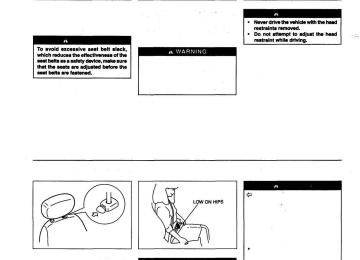
Head restraints are designed to help reduce the risk of neck injuries in the case of an accident. Adjust the head restraint to the position which places the top of the head restraint closest to the top or your ears.
23
BEFORE DRIVING
SEAT BELTS
60G-03-016
70F-01-022E
To raise the head restraint, pull upward ort the restraint until it clicks. To lower the restraint, push down on the restraint while holding in the lock lever. If a head restraint must be removed (for cleaning, replacement, etc.), push in the lock lever and pull the head restraint all the way out.
Wear your Seat Belts at All Times.
WARNING
Never allow persons to ride in the cargo area of a vehicle. In the event of an accident, there is a much greater risk of injury for persons who are not riding In a seat with their seat belt securely fastened. Seat belts should always be adjusted so the lap portion of the belt is worn low across the pelvis, not across the waist. Shoulder straps should be
3-11
3-10
60G-74E
WARNING
1 worn on the outside shoulder only, and never under the arm. Seat belts should never be worn with the straps twisted and should be adjusted as tightly as is comfortable to provide the protection for which they have been designed. A slack belt will provide less protection than one which is snug. Make sure that each seat belt buckle is inserted into the proper buckle catch. It is possible to cross the buckles in the rear seat. Do not wear your seat belt over hard or breakable objects in your pockets or on your clothing. If an accident occurs, objects such as glasses, pens, etc. under the seat belt can cause injury. Never use the same seat belt on more than one occupant and never attach a seat belt over an infant or child being held on an occupant's lap. Such seat belt use could cause serious injury in the event of an accident. _K
24
60G-74E
BEFORE DRIVING
Pregnant women should use seat belts, although specific recommen- dations about restraint use should be made by the woman's medical advisor. Periodically inspect seat belt assemblies for excessive wear and damage. Seat belts should be replaced if webbing becomes frayed, contaminated, or damaged in any way. It is essential to replace the entire seat belt assembly after it has been stressed in an impact, even if damage to the assembly is not obvious. Infants and small children should never be transported unless they are properly restrained. Restraint systems for infants and small children can be purchased locally and should be used. Make sure that the system you purchase meets applicable safety standards. Read and follow all the directions the manufacturer.
provided
by
Avoid contamination of seat belt webbing by polishes, oils, chemicals, and particularly battery acid. Cleaning may safely be carried out using mild soap and water. For children, if the shoulder belt irritates the neck or face, move the child closer to the center of the vehicle.
A WARNING
Be sure to inspect all seat belt assemblies after any collision. Any seat belt assembly which was in use during a collision (other than a very minor one) should be replaced, even if damage to the assembly is not obvious. Any seat belt assembly which was not in use during a collision should be replaced if it does not function properly or is damaged in any way.
70F-01-021
There are two types of seat belt, "Lap-shoulder belt" and "Lap belt".
To fasten the seat belt, sit up straight and well back in the seat, pull the buckle tongue attached to the seat belt across your body and slide it into the buckle catch on the opposite side until you hear a "click".
25
BEFORE DRIVING
3-12
60G-74E
70F-01-022E
70F-01-023E
70F-01-024E
To reduce the risk of sliding under the belt during a collision, position the lap portion of the belt across your lap as low on your hips as possible and adjust the belt to a snug fit using the proper method for each type of the belt as described below. Make sure that the belt is not twisted.
To unfasten the belt, press the release button on the buckle catch.
To Adjust the Belt • Lap-shoulder belt
Pull the shoulder portion of the belt upwards through the tongue plate.
The length of the diagonal shoulder strap adjusts itself to allow freedom of movement. The seat belt has an emergency locking retractor (ELR), which is designed to lock the seat belt only during a sudden stop or impact.
3-13
26
60Q-74E
BEFORE DRIVING
70F-01-025
60G-03-017
60G-03-018E
Your vehicle is equipped with the shoulder anchor height adjusters for the front seat belts, adjust the shoulder anchor height so that the shoulder belt rides on the center of the outboard shoulder. To adjust the shoulder anchor height, slide the anchor up or down while pulling the lock knob out. After adjustment, make sure that the acnhor is securely locked.
No modifications or additions of any sort should be made to the seat belt or its operating mechanism.
27
BEFORE DRIVING
Seat Belt Hanger (if equipped)
When you move a seatback, make sure the belt webbing is hooked in the belt hangers so the seat belts are not caught by the seatback, seat hinge, or seat latch. This helps prevent damage to the belt system.
Lap belt On this belt the adjuster is incorporated in the tongue unit. To tighten the belt, pull the free end of the belt across alongside the lap strap until it is adjusted to a snug comfortable position.
3-14
60G-74E
60G-03-019E
60G-03-020E
70F-01-030
To lengthen, release the tongue from the buckle unit, pull the tongue (adjuster) in the direction of the arrow, at right angles to the belt. The tongue should then be refitted into the buckle unit and the belt tightened as previously described.
NOTE: To identify the center seat belt buckle catch and tongue in the rear seat, "CENTER" is moulded on the buckle catch and tongue of the center lap belt. The buckle catches are designed so a buckle tongue can not be inserted into the wrong buckle catch.
Child Restraint Systems MARUTI highly recommends that you use a child restraint system to restrain infants and small children. Many different types of child restraint systems are available; make sure that the restaint system you select meets applicable safety standards.
3-15
All child restraint systems are designed to be secured in vehicle seats by lap belts or the lap portion of lap-shoulder belts. Whenever possible, Maruti recommends that child restraint systems be installed on the rear seat. According to accident statistics children are safer when properly restrained in rear seating positions than in front seating positions.
28
60G-74E
BEFORE DRIVING
If you must use a front-facing child restraint in the front passenger's seat, adjust the passenger's seat as far back as possible.
Children could be endangered in a crash if their child restraints are not properly secured in the vehicle. When installing a child restraint system, be sure to follow the instructions below. Be sure to secure the child in the restraint system according to the manufacturer's Instructions.
60G-03-021E
70F-01-031
Try moving the child restraint system in all directions, to make sure it is securely installed. Tighten the belt if necessary.
Installation with lap-shoulder seat belts Note: The lap-shoulder belts of your vehicle have emergency locking retractors (ELRs) that can not function as an automatic locking retractor (ALR). Use the installation method described in the instructions provided by the child restraint system manufacturer that does not require the ALR function.
Install your child restraint system according to the instructions provided by the child restraint system manufacturer. Make sure that the seat belt is securely latched.
29
BEFORE DRIVING
3-16
60G-74E
70F-01-032E
Installation with a lap belt Install your child restraint system according to the instructions provided by the child restraint system manufacturer.
To lengthen or tighten the belt, refer to the "Lap belt" item in this "SEAT BELTS" section. After making sure that the seat belt is securely latched, try moving the child restraint system in all directions, to make sure it is securely installed. If you need to tighten the belt, pull the free end of the webbing.
3-17
30
60G-74E
STEERING COLUMN CONTROLS
STEERING COLUMN CONTROLS
ignition Switch Lighting/Tum Signal Control Lever Windscreen Wiper and Washer Lever Horn Rear Wiper and Washer(lf equipped)
4.1
4-2
4-4
4.5
4-531
STEERING COLUMN CONTROLS
60G-74E
IGNITION SWITCH
60G-04-001E
70F-02-002
60G-04-002E
To avoid possible injury, do not operate controls by reaching through the steering wheel.
The ignition switch has the following four positions:
Do not use any locally made key. Should you require duplicate key, place your order with MARUTI dealer only.
LOCK This is the normal parking position. It is the only position in which the key can be removed. You must push in the key to turn it to the "LOCK" position. The "LOCK" position locks the ignition, and prevents normal use of the steering wheel after the key is removed. To release the steering lock, fully insert the key and turn it clockwise to one of the other positions. If you have trouble turning the key to unlock the steering, try turning the steering wheel slightly to the right or left while turning the key.
4-1
32
6OG-74E
ACC Accessories such as the radio can operate, but the engine is off. ON This is the normal operating position. All electrical systems are on. START This is the position for starting the engine using the starter motor. The key should be released from this position as soon as the engine starts.
Never remove the ignition key while the vehicle is moving. The steering wheel will lock and you will not be able to steer the vehicle. Do not leave children alone In a parked vehicle. Unattended children could cause accidental movement of the vehicle, which could result in severe personal Injury. Always remove the key when parked to prevent unintentional operation of the vehicle and to improve security.
33
STEERING COLUMN CONTROLS
CAUTION
Do not use the starter motor for more than 15 seconds at a time. If the engine does not start; wait 15
seconds before trying again. If the engine does not start after several attempts, check the fuel and ignition systems or consult your MARUTI dealer. Do not leave the ignition switch in the "ON" position if the engine is not running as the battery will discharge.STEERING COLUMN CONTROLS
LIGHTING/TURN SIGNAL CONTROL LEVER
60G-04-003
This control lever is located on the outboard side of the steering column. Operate the lever as described below.
Lighting Operation To turn the lights on or off, twist the knob on the end of the lever. There are three positions: in the "OFF" position all lights are off; in the middle position the front parking lights, tail- lights, registration plate light, and instrument lights are on, but the headlights are off; in the third position the headlights come on in addition to the other lights.
4-2
60G-74E
60G-04-004E
60G-04-005
With the headlights on, push the lever forward to switch to the high beams (main beams) or pull the lever toward you to switch to the low beams. When the high beams (main beams) are on, a light on the instrument panel will come on. To flash the high beams (main beams) pull the lever slightly towards you and release it.
Lights "On" Reminder (if Equipped) A buzzer/chime sounds to remind you to turn off the lights if they are left on when the ignition key is removed and the driver's door is opened.
Turn Signal Operation With the ignition switch in the "ON" position, move the lever up or down to activate the left or right turn signals.
Normal Turn Signal Move the lever clockwise until it clicks to signal a right turn or anticlockwise to signal a left turn. When the turn is completed, the signal will cancel and the lever will return to its normal position.
6OG-04-006
60G-04-006Lane Change Signal Some times, such as when changing lanes, the steering wheel is not turned far enough to cancel the turn signal. For convenience, you can flash the turn signal by moving the lever part way and holding it there. The lever will return to its normal position when you release it.
4-3
34
60G-74E
WINDSCREEN WIPER AND WASHER LEVER
STEERING COLUMN CONTROLS
60G-04-007E
60G-04-008E
60G-04-009E
If the lever is equipped with "INT TIME" control, turn the control toward the "SLOW" or "FAST' positions to adjust the intermittent wiper operation to the desired interval.
Windscreen Washer To spray windscreen washer fluid, pull the lever toward you. The windscreen wipers will automatically turn on at low speed if they are not already on and the "INT" position is equipped.
Windscreen Wipers To turn the windscreen wipers on, move the lever down to one of the three operating positions. In the "INT position (if equipped), the wipers operate intermittently. The "INT' position is very convenient for driving in mist or light rain. In the "LO" position, the wipers operate at a steady low speed. In the "HI" position, the wipers operate at a steady high speed. To turn off the wipers, move the lever back to the "OFF position.
35
60G-04-011E The operation of windscreen wiper and washer Type-2 is same as Type-1.
To prevent windscreen icing in cold weather, turn on the defroster to heat the windscreen before and during windscreen washer use. Do not use radiator antifreeze in the windscreen washer reservoir. It can severely impair visibility when sprayed on the windscreen, and can also damage your vehicle's paint.
4-4
60G-74E
HORN
REAR WIPER AND WASHER (if equipped)
60G-04-010
Press the horn button of the steering wheel to sound the horn. The horn will sound with the ignition switch in any position.
Press the button located at the end of the windscreen wiper and washer lever to operate the rear washer and turn the lever anti clockwise to operate the rear washer.
STEERING COLUMN CONTROLS
CAUTION
To help prevent damage to the windscreen wiper and washer system components, you should take the following precautions: • Do not continue to hold in the lever when there is no windscreen washer fluid being sprayed or the washer motor can be damaged.
• Do not attempt to remove dirt from a dry windscreen with the wipers or you can damage the windscreen and the wiper blades. Always wet the windscreen with washer fluid before operating the wipers.
• Clear ice or packed snow from the wiper blades before using the wipers.
• Check the washer fluid
level regularly. Check it often when the weather is bad.
• Only fill the washer fluid reservoir 3/4 full during cold weather to allow room the temperature falls low enough to freeze the solution.
for expansion
if
4-5
36
60G-74E
INSTRUMENT PANEL
INSTRUMENT PANEL
Instrument Panel Instrument Cluster Warning and Indicator Lights Speedometer/Odometer/Tripmeter (if equipped) Tachometer (if equipped) Fuel Gauge Temperature Gauge Hazard Warning Switch Rear Window Defroster Switch (if equipped) Cigarette Lighter (if equipped) Ashtray Glove Box Heating System (if equipped) System Operating Instructions Air Conditioning System (if equipped) System Operating Instructions
5-1
5-2
5-3
5-5
5-6
5-6
5-6
5-7
5-7
5-7
5-8
5-8
5-9
5-10
5-13
5-1360G-74E
37
INSTRUMENT PANEL
INSTRUMENT PANEL
Instrument cluster Ignition switch
1. 2. 3. Lighting switch/Turn signal and
dimmer switch
4. Windscreen wiper and washer
switch
5. Hazard warning switch 6. Rear window defroster switch
(if equipped)
7. Other switches (if equipped) 8. Heater control panel 9. Audio system (if equipped) 10. Cigarette lighter (if equipped) 11. Ashtray 12. Bonnet release 13. Center ventilator 14. Side ventilator 15. Side defroster 16. Glove box 17. Fuse box 18. Cup holder (if equipped)
5-1
38
60G-74E
INSTRUMENT CLUSTER
INSTRUMENT PANEL
© Speedometer ® Odometer © Trip meter (if equipped) © Trip meter reset knob © Tachometer (if equipped) © Fuel gauge ® Temperature gauge © Warning and indicator lights
60G-05-002
39
INSTRUMENT PANEL
WARNING AND INDICATOR LIGHTS
70F-07-070
Brake fluid level warning/Parking Brake Indicator light This light operates under three conditions: 1) when the ignition switch is turned to the "START' position, 2) when the fluid in the brake fluid reservoir falls below the specified level or 3) when the parking brake is not fully released and the ignition switch is in the "ON" position. The light should go out after starting the engine and fully releasing the parking brake, if the fluid in the brake fluid reservoir is adequate. If the light does not go off or comes on whilst you are driving, it may mean that there is something wrong with the vehicle's braking system. If this happens, you should: 1) Pull off the road and stop carefully.
Remember that stopping distance may be longer, you may have to push harder on the pedal, and the pedal may go down farther than normal.
5-3
5-2
60G-74E
70F-03-039
Oil Pressure Light This light comes on when the ignition switch is turned on, and goes out when the engine is started. The light will come on and remain on if there is insufficient oil pressure. If the light comes on when driving, pull off the road as soon as you can and stop the engine. Check the oil level and add oil if necessary (see pages 9-8 and 9-9). If there is enough oil, the lubrication system should be inspected by your MARUTI dealer before you drive the vehicle again.
2) Test the brakes by carefully starting and
stopping at the side of the road.
3) If you determine that it is safe, drive carefully at low speed to the nearest dealer for repairs.
or 4)
Have the vehicle towed to the nearest dealer for repairs.
If any of the following conditions occur, you should Immediately ask your MARUTI dealer to inspect the brake system. • If the brake fluid level warning light does not go out after the engine has been started and the parking brake has been fully released.
• If the brake fluid level warning light does not come on when the ignition switch is turned to the "START" position.
• If the brake fluid level warning light comes on at any time during vehicle operation.
NOTE: Because the disc brake system is self adjusting, the fluid level will drop as the brake pads become worn. Replenishing the brake fluid reservoir is considered normal periodic maintenance.
40
60G-74E
INSTRUMENT PANEL
60G-09-002
70F-03-009
CAUTION
If you operate the engine with this light on, severe engine damage can result. Do not rely on the Oil Pressure Light to indicate the need to add oil. Be sure to periodically check the engine oil level (see pages 9-8 and 9-9).
Charging Light This light comes on when the ignition switch is turned on, and goes out when the engine is started. The light will come on and remain on if there is something wrong with the battery charging system. If the light comes on when the engine is running, the charging system should be inspected immediately by your MARUTI dealer.
CAUTION
Do not continue driving long with the charging light ON as this will drain the battery 'dead'.
41
INSTRUMENT PANEL
SPEEDOMETER/ODOMETER/ TRIPMETER (if equipped)
72F-05-027
"Malfunction Indicator" Light Your vehicle has a computer-controlled emission control system. A "Malfunction Indicator" light is provided on the instrument panel to indicate when it is necessary to have the emission control system serviced. The "Malfunction Indicator" light comes on when the ignition switch is turned to "ON" and goes out when the engine is started. If the "Malfunction Indicator" light comes on when the engine is running, there is a problem with the emission control system. Take the vehicle to your MARUTI dealer to have the problem corrected.
CAUTION
Continuing to drive the vehicle when the "Malfunction Indicator" light is on can cause permanent damage to the vehicle's emission control system, and can affect fuel economy and driveability.
5-4
60G-74E
70F-03-042
Turn Signal Indicators When you turn on the left or right turn signals, the corresponding green arrow on the instrument panel will flash along with the respective turn signal lights. When you turn on the hazard warning switch, both arrows will flash along with all of the turn signal lights.
Main Beam (High Beam) Indicator Light This indicator comes on when headlight main beams (high beams) are turned on.
70F-03-043
5-5
42
60G-05-003
© Speedometer © Odometer (D Trip meter © Trip meter reset knob
The speedometer indicates vehicle speed in km/h.The odometer records the total distance the vehicle has been driven. The tripmeter can be used to measure the distance travelled on short trips or between fuel stops. You can reset the tripmeter to zero by pushing the reset knob.
CAUTION
Keep track of your odometer reading and check the maintenance schedule regularly for required services. Increased wear or damage to certain parts can result from failure to perform required services at the proper mileage intervals and your warranty rights may be affected.
60G-74E
INSTRUMENT PANEL
TACHOMETER (if equipped)
FUEL GAUGE
TEMPERATURE GAUGE
60G-05-004
60G-05-005
60G-05-006
The tachometer indicates engine speed in revolutions per minute.
Never drive with the engine speed indicator in the red zone or severe engine damage can result.
This gauge gives an approximate indication of the amount of fuel in the fuel tank as shown in figure. "P stands for full and "E" stands for empty.
If the indicator gets in the red zone, refill the tank as soon as possible.
Note: This vehicle has fuel gauge of new design. Even when the ignition switch is "OFF", the needle will not return to "E" position but will show the reading.
When the ignition switch is on, this gauge indicates the engine coolant temperature. Under normal driving conditions, the indicator should stay within the normal, acceptable temperature range between "H" and "C". If the indicator approaches "H", and maintains that reading, overheating is indicated. Follow the instructions for engine overheating in the EMERGENCY REMEDIES section.
CAUTION
Continuing to drive the vehicle when engine overheating is indicated, can result in severe engine damage.
43
INSTRUMENT PANEL
5-6
60G-74E
HAZARD WARNING SWITCH
REAR WINDOW DEFROSTER SWITCH CIGARETTE LIGHTER (if equipped) (if equipped)
60G-05-007
60G-05-008
60G-05-009
Push in the hazard warning switch to activate the hazard warning lights. All four turn signal lights and both turn signal indicators will flash simultaneously. To turn off the lights, push the switch again.
Use the hazard warning lights to warn other traffic during emergency parking or when your vehicle could otherwise become a traffic hazard.
When the rear window is misted, push this switch to clear the window. An indicator light will be lit when the defroster is on. The defroster will only work when the ignition switch is in the "ON position. To turn off the defroster, push the switch again.
CAUTION
The rear window defroster uses a large amount of electricity. Be sure to turn off after the window has become clear.
To use the cigarette lighter, push it all the way into the receptacle and release it. It will automatically heat up and will pop out to its normal position when it is ready for use.
5-7
44
60G-74E
ASHTRAY
INSTRUMENT PANEL
GLOVE BOX
60G-05-010
843-05-011E
60G-05-011
Front Ashtray To remove the front panel ashtray for cleaning, push down on the metal plate, and pull the ashtray completely out of its holder.
Rear Ashtray To remove the rear ashtray, push down on the tongue and pull the ashtray out of its holder.
Make sure tobacco is fully extinguished before closing the ashtray. Never throw waste in the ashtray: it could create a fire hazard.
To open the glove box, pull the latch lever. To close it, push the lid until It latches securely. If a lock is equipped on the latch lever, lock the glove box by inserting the key and turning it clockwise and unlock the glove box by turning the key counterclockwise.
Never drive with the glove box lid open. It could cause injury if an accident occurs.
45
INSTRUMENT PANEL
HEATING SYSTEM (if equipped)
The heating system provides heating demisting, and ventilation. a. Windscreen defroster b. Side defroster c. Side outlet d. Center outlet e. Floor outlet
RECIRCULATED AIR
FRESH AIR
60G-05-013
5-9
5-8
60G-74E
60G-05-012
46
60G-74E
Description of Controls Function Buttons ©: These buttons are used to select one of the functions described below:
VENTILATION ©: Temperature- controlled air comes out of the center and side air outlets.
70F-03-029
BI-LEVEL ®: Temperature- controlled air comes out of the floor outlets and cooler air comes out of the center and side outlets. When the temperature control lever is in the fully "COOL" position or fully "HOT" position, however, the air from the floor outlets and the air from the center and side outlets will be the same temperature.
HEAT ©: Temperature-controlled air comes out of the floor outlets.
HEAT & DEFROST ©: Tempera- ture-controlled air comes out of the floor outlets, the windscreen de- froster outlets, and the side defroster outlets.
70F-03-030
70F-03-031
70F-03-032
47
INSTRUMENT PANEL
DEFROST ©: Temperature- controlled air comes out of the windscreen defroster outlets and the side defroster outlets.
Air Intake Lever ©:This lever is used to select between circulating outside air (FRESH AIR) or recirculating inside air (RECIRCULATED AIR).
Temperature Control Lever ©: This lever is used to control the temperature of the air that comes out of the air outlets.
Fan switch ©: This switch is used to turn on the fan and to select fan speed. There are five positions: OFF, LOW, MEDIUM, MEDIUM HIGH and HIGH.
INSTRUMENT PANEL
SYSTEM OPERATING INSTRUCTIONS
60G-05-014
Natural Ventilation Push the "VENTILATION" button and move the air intake lever to "FRESH AIR", the temperature control lever to the desired temperature position, and the fan switch to "OFF. Fresh air will flow through the vehicle when it is moving.
5-10
60G-74E
1I
A/C
1 OFF | | ••
= 11
60G-05-015
60G-05-016
60G-05-017
Forced Ventilation The lever settings are the same as for natural ventilation except you move the fan switch to a position other than "OFF".
Normal Heating (Using outside air) Push the "HEAT" button and move the air intake lever to "FRESH AIR", the temperature control lever to the desired temperature position, and the fan switch to the desired fan speed position. Moving the fan switch to a higher fan speed position increases heating efficiency.
Quick Heating (Using recirculated air) The lever settings are the same as for normal heating except you move the air intake lever to "RECIRCULATED AIR". If you use this heating method for an extended period of time, the air the vehicle can become contaminated and the windows can become misty. Therefore, use this method only for quick heating and change to the normal heating method as soon as possible.
in
5-11
60G-74E
INSTRUMENT PANEL
60G-05-018
60G-05-019
60G-05-020
Cool Face/Warm Feet Push the "BI-LEVEL" button and move the air intake lever to "FRESH AIR", the temperature control lever to the desired temperature position, and the fan switch to the desired fan speed position. Unless the temperature control lever is in the fully "COOL" position or fully "HOT position, the air that comes out of the center and side outlets will be cooler than the air that comes out of the floor outlets.
Defrosting/Warm Feet Push the "HEAT & DEFROST' button and move the air intake lever to "FRESH AIR", the temperature control lever to the desired temperature position, and the fan switch to "HIGH". When the windscreen has become clear, move the fan switch to the desired fan speed position.
Defrosting Push the "DEFROST' button and move the air intake lever to "FRESH AIR", the temperature control lever to the desired temperature position, and the fan switch to "HIGH" Moving the temperature control lever to a higher temperature position increases defrosting efficiency. When the windscreen has become clear, move the fan switch to the desired fan speed position.
49
INSTRUMENT PANEL
AIR CONDITIONING SYSTEM (if equipped)
SYSTEM OPERATING INSTRUCTIONS
5-12
60G-74E
60G-05-021
The air conditioning system can be used to provide cooling and dehumidifying, as described below. To turn on the air conditioning system, push in the A/C button and move the fan switch to a position other than "OFF". An indicator light will come on when the air conditioning system is on. To turn off the air conditioning system, push the A/C button again. During operation of the air conditioner, you may notice slight changes in engine speed. These changes are normal, the system is designed so that the compressor turns on or off to maintain the desired temperature. Less operation of the compressor results in better fuel economy.5-13
60G-05-022
60G -05-023
in
the A/C button and
Normal Cooling (using outside air) Push the "VENTILATION" button, and the move the air intake lever to "FRESH AIR", the temperature control lever to the "COOL" position, and the fan switch to the desired fan speed position. Moving the fan switch to a higher fan speed position increases cooling efficiency.
If the ambient temperature is high enough to cause insufficient cooling, use the "Quick Cooling" as following.
Quick Cooling (Using recirculated air) The lever settings are the same as for normal cooling except you move the air intake lever to "RECIRCULATED AIR". If you use this cooling method for a extended period of time, the air the vehicle can become contaminated. Therefore, you should occasionally move the air intake lever to "FRESH AIR".
in
NOTE: If your vehicle has been left in the sun with the windows closed, it will cool faster if you open the windows briefly while you operate the air conditioner with the air intake lever at "FRESH AIR" and the fan at high speed.