- 2010 Nissan Titan Owners Manuals
- Nissan Titan Owners Manuals
- 2007 Nissan Titan Owners Manuals
- Nissan Titan Owners Manuals
- 2006 Nissan Titan Owners Manuals
- Nissan Titan Owners Manuals
- 2009 Nissan Titan Owners Manuals
- Nissan Titan Owners Manuals
- 2012 Nissan Titan Owners Manuals
- Nissan Titan Owners Manuals
- 2008 Nissan Titan Owners Manuals
- Nissan Titan Owners Manuals
- 2005 Nissan Titan Owners Manuals
- Nissan Titan Owners Manuals
- 2011 Nissan Titan Owners Manuals
- Nissan Titan Owners Manuals
- 2004 Nissan Titan Owners Manuals
- Nissan Titan Owners Manuals
- Download PDF Manual
-
LIC0554
Adjustable (if so equipped)
Armrest (if so equipped)
Position the arm on the adjustable cup holder so that the cup is held securely.
2nd row (rear of front console)
(if so equipped)
To open the 2nd row cup holders (rear of front console), lower the lid. To close, raise the lid.
Instruments and controls 2-45
2nd row bench (if so equipped)
Bottle holder — Type A
Bottle holder — Type B
LIC0556
LIC0558
LIC0624
CAUTION
● Do not use bottle holder for any other objects that could be thrown about in the vehicle and possibly injure people during sudden braking or an accident. ● Do not use bottle holder for open liquid
containers.
2-46 Instruments and controls
CAUTION
● Do not store a total load of more than 22
storageinside
the
(10
lbs kg) compartment.
LIC0626
GROCERY HOOKS (if so equipped) The grocery hooks allow for standard size plastic grocery bags to hang side by side. To access the grocery hooks, fold up the rear bench seat. See “Folding the rear bench seat” in the “Safety — Seats, seat belts and supplemental restraint system” section earlier in this manual.CAUTION
Do not apply a total load of more than 18
lbs (8 kg) to a single grocery hook.LIC0625
LOCKABLE BEDSIDE STORAGE COMPARTMENT (if so equipped) To access the bedside storage compartment, hold the key hole cover open and insert the master key. Turn the key clockwise to unlock the lid.
The tray inside the bedside storage compartment is adjustable.
The bedside storage compartment will automati- cally lock when the lid is closed. You do not need to use the key.
● Do not use the storage compartment or storage compartment lid as a step. Do- ing so may damage them.
Instruments and controls 2-47
Driver’s side power window switch The driver’s side control panel is equipped with switches to open or close the front and rear passenger windows. To open a window, push the switch and hold it down. To close a window, pull the switch and hold it up. To stop the opening or closing function at any time, simply release the switch.
WIC0845
1. Window lock button 2. 3. 4. 5. 6.
Power door lock switch Front passenger side automatic switch Right rear passenger window switch Left rear passenger window switch Driver side automatic switch
WINDOWS
POWER WINDOWS (if so equipped)
WARNING
● Make sure that all passengers have their hands, etc. inside the vehicle while it is in motion and before closing the windows. Use the window lock switch to prevent unexpected use of the power windows.
● Do not leave children unattended inside the vehicle. They could unknowingly ac- tivate switches or controls and become trapped in a window. Unattended chil- dren could become involved in serious accidents.
The power windows operate when the ignition switch is placed in the ON position, or for about 45 seconds after the ignition switch is placed in the OFF position. If the driver’s or passenger’s door is opened during this period of about 45
seconds, power to the windows is canceled.2-48 Instruments and controls
LIC0580
LIC0581
LIC0410
Rear power window switch The rear power window switches open or close only the corresponding windows. To open the window, push the switch and hold it down 䊊1 . To close the window, pull the switch up 䊊2 .
Front passenger’s power window switch The passenger’s window switch operates only the corresponding passenger’s window. To open the window, push the switch and hold it down 䊊1 . To close the window, pull the switch up 䊊2 . Locking passengers’ windows When the window lock button is depressed, only the driver’s side window can be opened or closed. Push it again to cancel the window lock function.
Automatic operation To fully open a window equipped with automatic operation, press the window switch down (only driver’s side shown) to the second detent and release it; it need not be held. The window auto- matically opens all the way. To stop the window, lift the switch up while the window is opening.
To fully close a window equipped with automatic operation, pull the switch up to the second detent and release it; it need not be held. To stop the window, press the switch down while the window is closing.
Instruments and controls 2-49
Auto-reverse function The auto-reverse function can be activated when a window is closed by automatic operation. Depending on the environment or driving conditions, the auto-reverse function may be activated if an impact or load similar to something being caught in the window oc- curs.
WARNING
There are some small distances immedi- ately before the closed position which cannot be detected. Make sure that all passengers have their hands, etc., inside the vehicle before closing the window.
the dealer
If the vehicle’s battery is disconnected, replaced, or jump started, the power window auto-reverse function may not operate properly. If this occurs, please contact to re-initialize the power window auto-reverse system. If the control unit detects something caught in a window equipped with automatic operation as it is closing, the window will be immediately low- ered.
2-50 Instruments and controls
WIC0263
MANUAL WINDOWS (if so equipped) The side windows can be opened or closed by turning the hand crank on each door.LIC0627
REAR SLIDING WINDOW (if so equipped) Squeeze the handles of the lever 䊊1 , then slide the window open 䊊2 .
MOONROOF (if so equipped)
NOTE: If the rear power window (if so equipped) is lowered while the defroster switch is on, the rear window defroster will automati- cally shut off. The heated outside mirrors (if so equipped) will remain on. The rear win- dow defroster will automatically turn on when the rear power window is fully closed if the switch is on.
LIC1553
REAR POWER WINDOW SWITCH (if so equipped) To open the rear power window, push in and hold the switch.
To close the rear power window, pull out and hold the switch.
To stop the opening or closing function at any time, simply release the switch.
WIC0812
AUTOMATIC MOONROOF The moonroof will only operate when the ignition switch is placed in the ON position. The auto- matic moonroof is operational for about 45 sec- onds, even if the ignition switch is placed in the ACC or OFF position. If the driver’s door or the front passenger’s door is opened during this period of about 45 seconds, power to the moon- roof is canceled. Sliding the moonroof To fully open the moonroof, push the switch to- ward the open position 䊊3 .
Instruments and controls 2-51
To fully close the moonroof, push the switch toward the close position 䊊4 . To open or close the moonroof part way, push the switch in any direction 䊊5 while the moonroof is sliding open or closed to stop it in the desired position. Tilting the moonroof To tilt the moonroof up, push the tilt switch to- ward the up position 䊊1 . To tilt the moonroof down, push the tilt switch toward the down position 䊊2 . Restarting the moonroof sliding switch The sliding switch will become inoperable after the battery terminal is disconnected, the electri- cal supply interrupted and/or some abnormality detected. Use the following reset procedure to return moonroof operation to normal.
1.
If the moonroof lid is open, push the tilting switch repeatedly toward the down position 䊊2 to fully close the lid.
2. Push and hold the tilting switch for more than 2 seconds toward the down position 䊊2 to reestablish the lid’s home position. The moonroof should now operate normally.
2-52 Instruments and controls
Auto reverse function (when closing or tilting down the moonroof) The auto reverse function can be activated when the moonroof is closed or tilted down by auto- matic operation when the ignition switch is placed in the ON position or for about 45 sec- onds after the ignition switch is placed in the OFF position. Depending on the environment or driving conditions, the auto reverse function may be activated if an impact or load similar to something being caught in the moonroof occurs.
WARNING
There are some small distances immedi- ately before the closed position which cannot be detected. Make sure that all passengers have their hands, etc., inside the vehicle before closing the moonroof.
When closing: If the control unit detects something caught in the moonroof as it moves to the front, the moonroof will immediately open backward.
When tilting down:
If the control unit detects something caught in the moonroof as it tilts down, the moonroof will im- mediately tilt up.
If the auto reverse function malfunctions and re- peats opening or tilting up the moonroof, keep pushing the tilt down switch within 5 seconds after it happens; the moonroof will fully close gradually. Make sure nothing is caught in the moonroof.
WARNING
● In an accident you could be thrown from the vehicle through an open moonroof. Always use seat belts and child restraints.
● Do not allow anyone to stand up or extend any portion of their body out of the moonroof opening while the vehicle is in motion or while the moonroof is closing.
CAUTION
● Remove water drops, snow, ice or sand
from the moonroof before opening.
● Do not place heavy objects on the
moonroof or surrounding area.
INTERIOR LIGHT
Sunshade Open and close the sunshade by sliding it for- ward or backward. If the moonroof does not close Have your NISSAN dealer check and repair the moonroof.
Type A
Type B
LIC0585
LIC0630
The interior light has a three-position switch and operates regardless of ignition switch position. When the switch is in the ON position 䊊1 , the interior lights illuminate, regardless of door posi- tion. The lights will go off after about 30 minutes unless the ignition switch is placed in the ACC or ON position.
When the switch is in the DOOR or normal operation position 䊊2 , the interior lights, puddle lights (if so equipped) and cargo light will stay on for about 30 seconds when:
● The doors are unlocked by the keyfob, a key or the power door lock switch while all doors are closed and the ignition switch is in the OFF position.
● The driver’s door is opened and then closed while the key is removed from the ignition switch.
● The key is removed from the ignition switch
while all doors are closed.
Instruments and controls 2-53
PERSONAL LIGHTS (if so equipped)
LIC0587
CONSOLE LIGHT (if so equipped) The console light 䊊1 will turn on whenever the parking lights or headlights are illuminated. The console light brightness can be adjusted with the illumination brightness control.
LIC0623
The personal lights on the overhead console can be swiveled 360 degrees. To turn on the light, press the button. Press the button again to turn off the light.The lights will turn off while the 30 second timer is activated when: ● The driver’s door is locked by the keyfob, a
key, or the power door lock switch.
● The ignition switch is turned ON. When the switch is in the OFF position 䊊3 , the interior lights do not illuminate, regardless of door position. The puddle lights (if so equipped) and cargo light come on when any front or rear pas- senger door is opened. The lights will turn off automatically after 30 min- utes while doors are open to prevent the battery from becoming discharged.
NOTE: The footwell and door step lights (if so equipped) illuminate when the driver and passenger doors are open regardless of the interior light switch position. These lights will turn off automatically after about 30 minutes while doors are open to prevent the battery from becoming discharged.
CAUTION
Do not use for extended periods of time with the engine stopped. This could result in a discharged battery.
2-54 Instruments and controls
MAP LIGHTS (if so equipped)
HOMELINK姞 UNIVERSAL TRANSCEIVER (if so equipped)
LIC0586
To turn the map lights on, press the switches. To turn them off, press the switches again.
CAUTION
Do not use for extended periods of time with the engine stopped. This could result in a discharged battery.
The HomeLink姞 Universal Transceiver provides a convenient way to consolidate the functions of up to three individual hand-held transmitters into one built-in device. HomeLink姞 Universal Transceiver: ● Will operate most Radio Frequency (RF) devices such as garage doors, gates, home and office lighting, entry door locks and se- curity systems.
● Is powered by your vehicle’s battery. No separate batteries are required. If the vehi- cle’s battery is discharged or is discon- nected, HomeLink姞 will retain all program- ming.
Once the HomeLink姞 Universal Transceiver is programmed, retain the original trans- mitter for future programming procedures (Example: new vehicle purchases). Upon sale of the programmed HomeLink姞 Universal Transceiver buttons should be erased for security purposes. For additional information, refer to “Program- ming HomeLink姞” later in this section.
the vehicle,
WARNING
● Do not use the HomeLink姞 Universal Transceiver with any garage door opener that lacks safety stop and re- verse features as required by federal safety standards. (These standards be- came effective for opener models manufactured after April 1, 1982). A ga- rage door opener which cannot detect an object in the path of a closing garage door and then automatically stop and reverse, does not meet current federal safety standards. Using a garage door opener without these features in- creases the risk of serious injury or death.
● During the programming procedure your garage door or security gate will open and close (if the transmitter is within range). Make sure that people or objects are clear of the garage door, gate, etc. that you are programming.
● Your vehicle’s engine should be turned off while programming the HomeLink姞 Universal Transceiver.
Instruments and controls 2-55
5.
grammed device, press and hold the pro- grammed HomeLink姞 button — releasing when the device begins to activate. If the indicator light on the HomeLink姞 blinks rapidly for 2 seconds and then turns solid, HomeLink姞 has picked up a “rolling code” garage door opener signal. You will need to proceed with the next steps to train the HomeLink姞 to complete the programming which may require a ladder and another per- son for convenience.
6. Press and release the “smart” or “learn” pro- gram button located on the garage door opener’s motor to activate the “training mode”. This button is usually located near the antenna wire that hangs down from the motor. If the wire originates from under a light lens, you will need to remove the lens to access the program button.
NOTE: Once you have pressed and released the program button on the garage door open- er’s motor and the “training light” is lit, you have 30 seconds in which to perform step 7. Use the help of a second person for conve- nience to assist when performing this step.
WIC0986
PROGRAMMING HOMELINK姞 1. To begin, press and hold the two outer HomeLink姞 buttons (to clear the memory) until the indicator light 䊊1 blinks (after 20
seconds). Release both buttons.2. Position the end of the hand-held transmitter 1 - 3 inches (26 - 76 mm) away from the HomeLink姞 surface.
2-56 Instruments and controls
WIC0987
3. Using both hands, simultaneously press and hold both the HomeLink姞 button you want to program and the hand-held transmitter but- ton.DO NOT release the buttons until step 4 has been completed.
4. Hold down both buttons until the indicator light on the HomeLink姞 flashes, changing from a “slow blink” to a “rapidly flashing blink”. This could take up to 90 seconds. When the indicator light flashes rapidly, both buttons may be released. The rapidly flash- ing light indicates successful programming. To activate the garage door or other pro-
7. Within 30 seconds of pressing and releas- ing the garage door opener’s program but- ton, quickly and firmly press and release the HomeLink姞 button you’ve just programmed. Press and release the HomeLink姞 button up to 3 times to complete the training.
8. Your HomeLink姞 button should now be pro- grammed. (To program the remaining HomeLink姞 buttons for additional door or gate openers, follow steps 2-4 only.)
all
previously
NOTE: Do not repeat step 1 unless you want to “clear” programmed HomeLink姞 buttons. If you have any questions or are having difficulty programming your HomeLink姞 buttons, refer to the HomeLink姞 web site at: www.homelink.com or call 1-800-355-3515. PROGRAMMING HOMELINK姞 FOR CANADIAN CUSTOMERS Prior to 1992, D.O.C. regulations required hand- held transmitters to stop transmitting after 2 sec- onds. To program your hand-held transmitter to HomeLink姞, continue to press and hold the HomeLink姞 button (see steps 2 - 4under “Pro- gramming HomeLink姞”) while you press and re- press (“cycle”) your hand-held transmitters every
2 seconds until the indicator light flashes rapidly (indicating successful programming).
NOTE:
When programming a garage door opener, etc., it is advised to unplug the device dur- ing the “cycling” process to prevent pos- sible damage to the garage door opener components. OPERATING THE HOMELINK姞 UNIVERSAL TRANSCEIVER The HomeLink姞 Universal Transceiver (once pro- grammed) may now be used to activate the ga- rage door, etc. To operate, simply press the ap- propriate programmed HomeLink姞 Universal Transceiver button. The amber indicator light will illuminate while the signal is being transmitted. PROGRAMMING TROUBLE- DIAGNOSIS If the HomeLink姞 does not quickly learn the hand- held transmitter information: ● replace the hand-held transmitter batteries
with new batteries.
● press and hold both the HomeLink姞 and hand-held transmitter buttons without inter- ruption.
● position the hand-held transmitter 1 - 3
inches (26 - 76 mm) away from the HomeLink姞 surface. Hold the transmitter in that position for up to 15 seconds. If HomeLink姞 is not programmed within that time, try holding the transmitter in another position – keeping the indicator light in view at all times.If you continue to have programming difficulties, please contact the NISSAN Consumer Affairs Department. The phone numbers are located in the Foreword of this manual. CLEARING THE PROGRAMMED INFORMATION Individual buttons cannot be cleared. However, to clear all programming, press and hold the two outside buttons and release when the indicator light begins to flash (approximately 20 seconds).
● position the hand-held transmitter with its from the
facing
away
battery HomeLink姞 surface.
area
Instruments and controls 2-57
DOC: ISTC 1763K1313
FCC I.D. CV2V67690REPROGRAMMING A SINGLE HOMELINK姞 BUTTON To reprogram a HomeLink姞 Universal Transceiver button, complete the following. 1. Press and hold the desired HomeLink姞 but- ton. Do not release the button until step 4
has been completed.2. When the indicator light begins to flash slowly (after 20 seconds), position the hand-held transmitter 1 - 3inches (26 - 76
mm) away from the HomeLink姞 surface.3. Press and hold the hand-held transmitter
button.
4. The HomeLink姞 indicator light will flash, first slowly and then rapidly. When the indicator light begins to flash rapidly, release both buttons.
The HomeLink姞 Universal Transceiver button has now been reprogrammed. The new device can be activated by pushing the HomeLink姞 button that was just programmed. This procedure will not affect any other programmed HomeLink姞 buttons.
2-58 Instruments and controls
IF YOUR VEHICLE IS STOLEN If your vehicle is stolen, you should change the codes of any non-rolling code device that has been programmed into HomeLink姞. Consult the Owner’s Manual of each device or call the manu- facturer or dealer of those devices for additional information. When your vehicle is recovered, you will need to reprogram the HomeLink姞 Univer- sal Transceiver with your new transmitter information.
FCC Notice:
This device complies with FCC rules part 15
and RSS-210 of Industry Canada. Opera- tion is subject to the following two condi- tions:(1) This device may not cause harmful in- terference and (2) This device must accept any interference that may be received, in- cluding interference that may cause undes- ired operation. This transmitter has been tested and com- plies with FCC and DOC/MDC rules. Changes or modifications not expressly ap- proved by the party responsible for compli- ance could void the user’s authority to op- erate the equipment.
3 Pre-driving checks and adjustments
Keys . . . . . . . . . . . . . . . . . . . . . . . . . . . . . . . . . . . . . . . . . . . . . 3-2
NISSAN vehicle immobilizer system keys (if so equipped) . . . . . . . . . . . . . . . . . . . . . . . . . . . . . . . . 3-2
Doors . . . . . . . . . . . . . . . . . . . . . . . . . . . . . . . . . . . . . . . . . . . . 3-3
Locking with key. . . . . . . . . . . . . . . . . . . . . . . . . . . . . . . . 3-3
Locking with inside lock knob . . . . . . . . . . . . . . . . . . . . 3-4
Locking with power door lock switch (if so equipped) . . . . . . . . . . . . . . . . . . . . . . . . . . . . . . . . 3-4
Wide Open doors (if so equipped) . . . . . . . . . . . . . . . 3-5
Child safety rear door lock (Crew Cab models only) . . . . . . . . . . . . . . . . . . . . . . . . . . . . . . . . . . . 3-7
Automatic door locks (if so equipped). . . . . . . . . . . . . 3-7
Remote keyless entry system (if so equipped). . . . . . . . . 3-8
How to use remote keyless entry system . . . . . . . . . . 3-9
Hood . . . . . . . . . . . . . . . . . . . . . . . . . . . . . . . . . . . . . . . . . . . 3-12
Fuel-filler door . . . . . . . . . . . . . . . . . . . . . . . . . . . . . . . . . . . 3-12
Fuel-filler cap . . . . . . . . . . . . . . . . . . . . . . . . . . . . . . . . . 3-12Steering wheel . . . . . . . . . . . . . . . . . . . . . . . . . . . . . . . . . . . 3-14
Tilt operation . . . . . . . . . . . . . . . . . . . . . . . . . . . . . . . . . . 3-14
Pedal position adjustment (if so equipped) . . . . . . . . . . 3-14
Sun visors . . . . . . . . . . . . . . . . . . . . . . . . . . . . . . . . . . . . . . . 3-15
Vanity mirrors (if so equipped). . . . . . . . . . . . . . . . . . . 3-16
Mirrors . . . . . . . . . . . . . . . . . . . . . . . . . . . . . . . . . . . . . . . . . . 3-16
Rearview mirror (if so equipped). . . . . . . . . . . . . . . . . 3-16
Automatic anti-glare rearview mirror (if so equipped) . . . . . . . . . . . . . . . . . . . . . . . . . . . . . . . 3-17
Outside mirrors . . . . . . . . . . . . . . . . . . . . . . . . . . . . . . . 3-18
Truck box . . . . . . . . . . . . . . . . . . . . . . . . . . . . . . . . . . . . . . . . 3-21
Tailgate. . . . . . . . . . . . . . . . . . . . . . . . . . . . . . . . . . . . . . . 3-21
Tie down hooks . . . . . . . . . . . . . . . . . . . . . . . . . . . . . . . 3-23
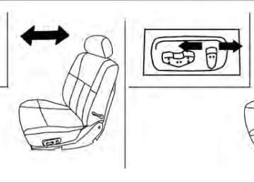
Automatic drive positioner (if so equipped) . . . . . . . . . . 3-24
Memory storage function . . . . . . . . . . . . . . . . . . . . . . . 3-24
Entry/exit function . . . . . . . . . . . . . . . . . . . . . . . . . . . . . 3-25
System operation. . . . . . . . . . . . . . . . . . . . . . . . . . . . . . 3-26KEYS
1.
2.
WPD0128
Two master keys (black) with transpon- der chip (if so equipped) and chrome NISSAN brand symbol on one side Valet key (black) with transponder chip (if so equipped) Key number plate Transponder chip (if so equipped)3. 4. A key number plate is supplied with your keys. Record the key number and keep it in a safe place (such as your wallet), not in the vehicle. If you lose your keys, see a NISSAN dealer for duplicates by using the key number. NISSAN does not record key numbers so it is very important to keep track of your key number plate.
3-2 Pre-driving checks and adjustments
cause the registration process will erase the memory of all key codes previously registered into the NISSAN Vehicle Immobilizer System. After the registration process, these components will only recognize keys coded into the NISSAN Vehicle Immobilizer System during registration. Any key that is not given to your dealer at the time of registration will no longer be able to start your vehicle. Do not allow the immobilizer system key, which contains an electrical transponder, to come into contact with salt water. This could affect system function.
A key number is only necessary when you have lost all keys and do not have one to duplicate from. If you still have a key, your NISSAN dealer can duplicate it. NISSAN VEHICLE IMMOBILIZER SYSTEM KEYS (if so equipped) You can only drive your vehicle using the master key which is registered to the NISSAN Vehicle Immobilizer System components in your vehicle. This key has a transponder chip in the key head.
The master key can be used for all the locks.
The valet key cannot be used for the console box lock, the beside storage compartment lock, or the glove box lock (if so equipped).
To protect belongings when you leave a key with someone, give them the valet key only. Never leave these keys in the vehicle. Additional or replacement keys: If you still have a key, the key number is not necessary when you need extra NISSAN Vehicle Immobilizer System keys. Your dealer can dupli- cate your existing key. As many as five NISSAN Vehicle Immobilizer System keys can be used with one vehicle. You should bring all NISSAN Vehicle Immobilizer System keys that you have to your NISSAN dealer for registration. This is be-
DOORS
When the doors are locked using one of the following methods, the doors can not be opened using the inside or outside door handles. The doors must be unlocked to open the doors.
WARNING
● Always have the doors locked while driving. Along with the use of seat belts, this provides greater safety in the event of an accident by helping to prevent persons from being thrown from the vehicle. This also helps keep children and others from unintentionally open- ing the doors, and will help keep out intruders.
● Before opening any door, always look
for and avoid oncoming traffic.
● Do not leave children unattended inside the vehicle. They could unknowingly ac- tivate switches or controls. Unattended children could become involved in seri- ous accidents.
Driver’s side
WPD0311
LOCKING WITH KEY Manual (if so equipped) To lock a door, turn the key toward the front of the vehicle 䊊1 . To unlock, turn the key toward the rear 䊊2 .
LPD0240
Power (if so equipped) The power door lock system allows you to lock or unlock all doors at the same time. Turning the key toward the front 䊊1 of the vehicle locks all doors. Turning the key one time toward the rear 䊊2 of the vehicle unlocks that door. From that position, returning the key to neutral 䊊3 (where the key can only be removed and inserted) and turning it toward the rear again within 5 seconds unlocks all doors 䊊4 .
Pre-driving checks and adjustments 3-3
Opening and closing windows The driver’s door key operation allows you to open and close windows equipped with auto- matic operation at the same time. ● To open the windows, turn the driver’s door key toward the rear of the vehicle for longer than 1 second after the door is unlocked. ● To close the windows, turn the driver’s door key toward the front of the vehicle for longer than 1 second after the door is locked.
Windows stop when the key cylinder is released.
3-4 Pre-driving checks and adjustments
Inside lock
LPD0241
LOCKING WITH INSIDE LOCK KNOB To lock the door without the key, move the inside lock knob to the lock position 䊊1 , then close the door. To unlock the door without the key, move the inside lock knob to the unlock position 䊊2 .
WPD0381
LOCKING WITH POWER DOOR LOCK SWITCH (if so equipped) To lock all the doors without a key, push the door lock switch (driver’s or front passenger’s side) to the lock position 䊊1 . When locking the door this way, be certain not to leave the key inside the vehicle. To unlock all the doors without a key, push the door lock switch (driver’s or front passenger’s side) to the unlock position 䊊2 .
Lockout protection When the power door lock switch (driver’s or front passenger’s side) is moved to the lock position with the key in the ignition switch and any door open, all doors will lock and then unlock automatically. This helps to prevent the keys from being accidently locked inside the vehicle.
LPD0278
WIDE OPEN DOORS (if so equipped)LPD0266
2. From the outside, pull the door handle 䊊1toward you.
CAUTION
Do not open the Wide Open door to the full open position while the fuel-filler door is open; only open it as far as the first detent. Opening the door to the full open position may damage the fuel-filler door and Wide Open door.
The Wide Open doors open nearly 180° to allow access to the rear of the cab. 1. Open the driver’s or passenger’s door.
Pre-driving checks and adjustments 3-5
LPD0267
From the inside, pull the inside door handle to- ward you. The door will unlock automatically.3. Open the door to the desired position.
LPD0265
3-6 Pre-driving checks and adjustments
4. When activated, the hazard warning lights will flash twice. When deactivated, the haz- ard warning lights will flash once.
5. The ignition switch must be placed in the OFF and ON position again between each setting change.
AUTOMATIC DOOR LOCKS (if so equipped) ● All doors lock automatically when the vehicle
speed reaches 15 MPH (24 km/h).
● All doors unlock automatically when the transmission is placed in the P (Park) posi- tion.
The automatic lock and unlock functions can be deactivated or activated indepen- dently of each other. To deactivate or activate the automatic door lock or unlock system, per- form the following procedure: 1. Close all doors. 2. Place the ignition switch in the ON position. 3. Do one of the following within 20 seconds of
performing Step #2: ● To change AUTO UNLOCK settings: push and hold the power door lock switch position (UNLOCK) for more to the than 5 seconds.
● To change AUTO LOCK settings: push and hold the power door lock switch to position (LOCK) for more the than 5 seconds.
LPD0242
CHILD SAFETY REAR DOOR LOCK (Crew Cab models only) Child safety locks help prevent the rear doors from being opened accidentally, especially when small children are in the vehicle. The child safety lock levers are located on the edge of the rear doors. When the lever is in the lock position, the door can be opened only from the outside.Pre-driving checks and adjustments 3-7
If a keyfob is lost or stolen, NISSAN rec- ommends erasing the ID code of that key- fob. This will prevent the keyfob from un- authorized use to unlock the vehicle. For information regarding the erasing proce- dure, please contact a NISSAN dealer.
REMOTE KEYLESS ENTRY SYSTEM (if so equipped)
It is possible to lock/unlock all doors, turn on the interior lights and puddle lights (if so equipped), and activate the panic alarm by using the keyfob from outside the vehicle.
Some settings for the keyfob, such as horn beep, can be adjusted. For vehicles without navigation system, refer to “Silencing the horn beep feature” in this section. For vehicles with navigation sys- tem, refer to “Vehicle electronic systems” in the “Display screen, heater, air conditioner and audio systems” section in this manual. Be sure to remove the key from the vehicle before locking the doors. The keyfob can operate at a maximum distance of approximately 33 ft (10 m) from the vehicle. The effective distance depends upon the conditions around the vehicle. As many as 5 keyfobs can be used with one vehicle. For information concerning the purchase and use of additional keyfobs, contact a NISSAN dealer. The keyfob will not function when: ● the battery is discharged. ● the distance between the vehicle and the
keyfob is over 33 ft (10 m).
The panic alarm will not activate when the key is in the ignition switch. 3-8 Pre-driving checks and adjustments
CAUTION
Listed below are conditions or occur- rences which will damage the keyfob: ● Do not allow the keyfob, which contains electrical components, to come into contact with water or salt water. This could affect the system function.
● Do not drop the keyfob. ● Do not strike the keyfob sharply against
another object.
● Do not change or modify the keyfob. ● Wetting may damage the keyfob. If the keyfob gets wet, immediately wipe until it is completely dry.
● Do not place the keyfob for an extended period in an area where temperatures exceed 140°F (60°C).
● Do not attach the keyfob with a key
holder that contains a magnet.
● Do not place the keyfob near equip- ment that produces a magnetic field, such as a TV, audio equipment and per- sonal computers.
● When the
button is pressed with all doors locked, the hazard warning lights flash twice and the horn beeps once as a re- minder that the doors are already locked.
● If a door is open and you press the
button, the doors will lock but the horn will not beep and the hazard warning lights will not flash.
The horn may or may not beep. For vehicles without navigation system, refer to “Silencing the horn beep feature” later in this section. For ve- hicles with navigation system, refer to “How to use the setting button” in the “Display screen, heater, air conditioner, audio and phone systems” section later in this manual.
LPD0209
HOW TO USE REMOTE KEYLESS ENTRY SYSTEM Locking doors 1. Close all windows.
2. Remove the key from the ignition switch.
3. Close the hood and all doors.
4. Press the
button on the keyfob. All the doors lock. The hazard warning lights flash twice and the horn beeps once to indicate all doors are locked.
LPD0210
Unlocking doors
button on the keyfob once.
Press the ● Only the driver’s door unlocks. ● The hazard warning lights flash once if all doors are completely closed with the ignition switch in any position except the ON posi- tion.
● The interior lights and puddle lights (if so equipped) turn on and the light timer acti- vates for 30 seconds when the interior light switch is in the DOOR position with the ignition switch in any position except the ON position.
Pre-driving checks and adjustments 3-9
Press the
button on the keyfob again within 5 seconds.
● All doors unlock. ● The hazard warning lights flash once if all
doors are completely closed.
The interior lights can be turned off without wait- ing 30 seconds by inserting the key into the ignition switch and placing it in the ON or START position, locking the doors with the keyfob or pushing the interior light switch to the OFF posi- tion. Auto relock When the button on the keyfob is pressed, all doors will lock automatically within 1 minute unless one of the following operations is per- formed: ● Any door is opened. ● A key is inserted into the ignition switch and
the switch is cycled from OFF to ON.
Linking the keyfob to automatic drive positioner memory If the vehicle is equipped with automatic drive positioner, the keyfob can be linked to a memory setting. See “Automatic drive positioner” in this section. 3-10 Pre-driving checks and adjustments
LPD0211
LPD0262
Silencing the horn beep feature If desired, the horn beep feature can be deacti- vated using the keyfob.
Using the panic alarm If you are near your vehicle and feel threatened, you may activate the panic alarm to call attention button on the by pressing and holding the keyfob for longer than 0.5 seconds. The panic alarm and headlights will stay on for 25
seconds. The panic alarm stops when: ● it has run for 25 seconds, or ● any button is pressed on the keyfob.For additional information, refer to “Interior light” in the “Instruments and controls” section in this manual.
NOTE:
If you change the horn beep and light flash feature with the keyfob, the display screen (if so equipped) will not show the current mode and cannot be used to change the mode. Use the keyfob to return to the pre- vious mode and re-enable the display screen control.
To deactivate: Press and hold the and
buttons for at least 2 seconds.
The hazard warning lights will flash 3 times to confirm that the horn beep feature has been deactivated.
To activate: Press and hold the and once more.
buttons for at least 2 seconds
The hazard warning lights will flash once and the horn will sound once to confirm that the horn beep feature has been reactivated.
Deactivating the horn beep feature does not si- lence the horn if the alarm is triggered. Using the interior lights
button on the keyfob once to Press the turn on the interior lights and puddle lights (if so equipped).
Pre-driving checks and adjustments 3-11
HOOD
FUEL-FILLER DOOR
LPD0244
LPD0263
䊊1 Pull the hood lock release handle located below the driver side instrument panel. The hood will spring up slightly.
䊊2 Push the lever at the front of the hood to the side as illustrated with your fingertips and raise the hood.
When closing the hood, lower it slowly and make sure it locks into place.
WARNING
● Make sure the hood is completely closed and latched before driving. Fail- ure to do so could cause the hood to fly open and result in an accident.
● If you see steam or smoke coming from the engine compartment, to avoid injury do not open the hood.
FUEL-FILLER CAP The fuel-filler cap is a ratcheting type. Turn the cap counterclockwise to remove. To tighten, turn the cap clockwise until ratcheting clicks are heard.
For additional information, see “Fuel recommen- dation (without Flexible Fuel Vehicle option)” and “Flexible fuel vehicle (FFV) fuel recommendation” in the “Technical and consumer information” sec- tion later in this manual.
3-12 Pre-driving checks and adjustments
WARNING
● Gasoline is extremely flammable and highly explosive under certain condi- tions. You could be burned or seriously injured if it is misused or mishandled. Always stop the engine and do not smoke or allow open flames or sparks near the vehicle when refueling.
● Do not attempt to top off the fuel tank after the fuel pump nozzle shuts off automatically. Continued refueling may cause fuel overflow, resulting in fuel spray and possibly a fire.
● Use only an original equipment type fuel-filler cap as a replacement. It has a built-in safety valve needed for proper operation of the fuel system and emis- sion control system. An incorrect cap can result in a serious malfunction and possible injury. It could also cause the malfunction indicator light to come on. ● Never pour fuel into the throttle body to
attempt to start your vehicle.
● Do not fill a portable fuel container on a truck bed liner, rubber truck bed mat, or other insulating material. Static elec- tricity can cause an explosion of flam- mable liquid, vapor or gas in any vehicle or trailer. To reduce the risk of serious injury or death when filling portable fuel containers: – Always place the container on the
ground when filling.
– Do not use electronic devices when
filling.
– Keep the pump nozzle in contact with the container while you are fill- ing it.
– Use only approved portable fuel con-
tainers for flammable liquid.
CAUTION
● Only vehicles with the E-85 filler door label can operate on E-85. Fuel system or other damage can occur if E-85 is used in vehicles that are not designed to run on E-85.
● If fuel is spilled on the vehicle body, flush it away with water to avoid paint damage.
● Tighten until the fuel-filler cap clicks. Failure to tighten the fuel-filler cap Mal- properly may cause the function Indicator Light (MIL) to illumi- light illuminates be- nate. If the cause the fuel-filler cap is loose or missing, tighten or install the cap and to continue vehicle. light should turn off after a The
drive
the
If the
few driving trips. light does not turn off after a few driving trips, have the vehicle inspected by a NISSAN dealer. ● For additional
information, see the “Malfunction Indicator Light (MIL)” in the “Instruments and Controls” section earlier in this manual.
Pre-driving checks and adjustments 3-13
STEERING WHEEL
PEDAL POSITION ADJUSTMENT (if so equipped)
CAUTION
Do not adjust the pedal position with your foot on the pedal.
TILT OPERATION
LPD0254
WARNING
Do not adjust the steering wheel while driving. You could lose control of your vehicle and cause an accident.
Pull the lock lever forward and hold it to adjust the steering wheel up or down to the desired posi- tion. Release the lock lever to lock the steering wheel in place.
LPD0255
The accelerator and brake pedals can be ad- justed for driving comfort.Use the pedal adjusting switch to adjust the brake and accelerator pedal position away from the driver 䊊1 or toward the driver 䊊2 . The brake and accelerator pedals cannot be ad- justed separately.
WARNING
Do not adjust the pedal position while driving. You can lose control of your ve- hicle and cause an accident.
3-14 Pre-driving checks and adjustments
SUN VISORS
Type B
LPD0264
䊊1 To block glare from the front, swing down the
main sun visor.
䊊2 To block glare from the side, remove the main sun visor from the center mount and swing the visor to the side.
䊊3 To block glare from the side and front, swing
down the sub-sun visor (if so equipped).
䊊4 Slide the extension sun visor (if so equipped)
in or out as needed.
Type A
LPD0273
CAUTION
● Do not store the sun visor before return- ing the extension to its original position.
● Do not pull the extension sun visor forc-
edly downward.
Pre-driving checks and adjustments 3-15
MIRRORS
Type A
Type B
WPD0168
LPD0257
VANITY MIRRORS (if so equipped) To access the vanity mirror, pull the sun visor down and flip open the mirror cover (if so equipped). Some vanity mirrors are illuminated and turn on when the mirror cover is open.
WPD0126
REARVIEW MIRROR (if so equipped) The night position 䊊1 reduces glare from the headlights of vehicles behind you at night. Use the day position 䊊2 when driving in daylight hours.WARNING
Use the night position only when neces- sary, because it reduces rear view clarity.
3-16 Pre-driving checks and adjustments
AUTOMATIC ANTI-GLARE REARVIEW MIRROR (if so equipped) The inside mirror is designed so that it automati- cally dims during night time conditions and ac- cording to the intensity of the headlights of the vehicle following you. The automatic anti-glare feature is activated when the ignition switch is in the ON position. The indicator light will illuminate when the auto- matic anti-glare feature is operating.
NOTE: Do not hang any objects over the sensors 䊊1 or apply glass cleaner to the sensors. Doing so will reduce the sensitivity of the sensors, resulting in improper operation.
For more information about the compass and compass features 䊊2
(if so equipped), see “Compass display” in the “Instruments and con- trols” section of this manual.Type A
LPD0446
Type A With the ignition switch placed in the ON posi- tion, press the ● To turn off
button as described:
the anti-glare feature, press button. The indicator light will turn
the off.
● To turn on the anti-glare feature, press button again. The indicator light
the will turn on.
The indicator light will illuminate when the auto- matic anti-glare feature is operating.
Pre-driving checks and adjustments 3-17
For information on HomeLink姞 Universal Trans- ceiver operation, see “HomeLink姞 Universal Transceiver” in the “Instruments and controls” section of this manual. For information on the compass and compass features 䊊2 , see “Compass display” in the “In- struments and controls” section of this manual. OUTSIDE MIRRORS
WARNING
● Objects viewed in the outside mirror on the passenger side are closer than they appear. Be careful when moving to the right. Using only this mirror could cause an accident. Use the inside mirror or glance over your shoulder to properly judge distances to other objects.
WPD0170
Manual control type (if so equipped) The outside mirror can be moved in any direction for a better rear view.
Type B
LPD0447
Type B With the ignition switch in the ON position, press the ● To turn off the automatic anti-glare feature, button. The indicator light
button as described:
press the will turn off.
● To turn on the automatic anti-glare feature, button again. The indicator
press the light will turn on.
The indicator light will illuminate when the auto- matic anti-glare feature is operating.
3-18 Pre-driving checks and adjustments
The lower portion of the trailer tow mirror can be moved manually in any direction for a better rear view.
LPD0237
LPD0279
Electric control type (if so equipped) The outside mirror remote control will operate only when the ignition switch is placed in the ACC or ON position. Move the small switch 䊊1 to select the right or left mirror. Adjust each mirror to the desired position using the large switch 䊊2 .
Trailer tow mirrors (if so equipped)
WARNING
Objects viewed in the convex portion of the trailer tow mirror are closer than they appear. Be careful when changing lanes or turning. Using only the convex mirror could cause an accident. Use the other mirrors or glance over your shoulder to properly judge distances to other objects.
Use the outside mirror remote control to adjust the top portion of the trailer tow mirror.
Pre-driving checks and adjustments 3-19
Type A
Type B
LPD0259
LPD0269
Manual folding outside mirrors (if so equipped) Pull the outside mirror toward the door to fold it.
LPD0268
Pull the trailer tow mirror outward to extend it to the desired position for better visibility while tow- ing a trailer.WARNING
Do not extend or retract mirrors while driv- ing. You may lose control of your vehicle and cause an accident.
CAUTION
Driving in tight spaces with mirrors ex- tended may cause damage to the vehicle.
3-20 Pre-driving checks and adjustments
headlights of trailing vehicles. The automatic anti- glare feature operates only when the ignition switch is placed in the ON position. The automatic anti-glare feature will be on when starting the vehicle. The indicator light on the automatic anti-glare rearview mirror will illuminate when the automatic anti-glare feature is operat- ing.
To turn off the anti-glare feature, press the button on the rearview mirror. The indicator light will turn off. To turn on the anti-glare feature again, press button on the rearview mirror. The in- the dicator light will turn on. For information on the automatic anti-glare rear- view mirror, see “Automatic anti-glare rearview mirror” in this section. Heated mirrors (if so equipped) Some outside mirrors can be heated to defrost, defog, or de-ice for improved visibility. For addi- tional information, see “Rear window and outside mirror defroster switch” in the “Instruments and controls” section of this manual.
TRUCK BOX
LPD0270
TAILGATE Opening the tailgate Pull the tailgate handle upward and lower the tailgate. The support cables hold the tailgate open.
When closing the tailgate, make sure the latches are securely locked. Do not drive the vehicle with the tailgate down, unless equipped with NISSAN’s Bed Extender (accessory) or equivalent in the extended position.
Pre-driving checks and adjustments 3-21
LPD0196
Power folding outside mirrors (if so equipped)
CAUTION
Do not manually fold the power folding mirrors. Manually folding the mirrors can damage the mirrors.
Push the switch to open or close the mirrors. Automatic anti-glare outside mirror (Driver’s side only) (if so equipped) The outside mirror will automatically dim during nighttime conditions to reduce the glare from the
Installing the tailgate 1. 2. Hold the tailgate at a 45 degree angle and
Insert the tailgate into the right side hinge.
insert into the left side hinge.
3. Continue to hold the tailgate at a 45 degree angle and attach the tailgate support cables.
4. Close the tailgate securely.
For proper truck box loading see “Vehicle loading information” in the “Technical and consumer in- formation” section of this manual.
WARNING
● It is extremely dangerous to ride in a cargo area inside a vehicle. In a colli- sion, people riding in these areas are more likely to be seriously injured or killed.
● Do not allow people to ride in any area of your vehicle that is not equipped with seats and seat belts.
● Be sure everyone in your vehicle is in a
seat and using a seat belt properly.
3-22 Pre-driving checks and adjustments
Removing the tailgate 1. Release the tailgate support cables.
LPD0271
CAUTION
● The tailgate is heavy. Two people should remove or install it. Be careful not to drop it during removal.
● After releasing the support cables, do not let the tailgate rest on the bumper.
2. Hold the tailgate at a 45 degree angle.
3. Pull the tailgate out from the left side hinge.
4. Slide the tailgate out of the right side hinge.
LPD0272
LTI0102
Locking the tailgate To unlock the tailgate, turn the key toward the passenger side of the vehicle 䊊1 . To lock, turn the key toward the driver side 䊊2 . Both the master key and the valet key can be used to lock and unlock the tailgate.
TIE DOWN HOOKS For your convenience, tie down hooks are placed at each corner of the truck box. These may be used to help secure cargo loaded into the truck box. ● The weight of the cargo load must be evenly distributed over both the front and the rear axles.
● All cargo should be securely fastened with ropes or straps to prevent it from shifting or sliding within the vehicle.
WARNING
● Properly secure all cargo with ropes or straps to help prevent it from sliding or shifting. In a sudden stop or collision, unsecured cargo could cause personal injury.
Pre-driving checks and adjustments 3-23
AUTOMATIC DRIVE POSITIONER (if so equipped)
The automatic drive positioner system has two features: ● Memory storage function ● Entry/exit function
3-24 Pre-driving checks and adjustments
mation, see “Seats” in the “Safety—Seats, seat belts and supplemental restraint sys- tem” section of this manual and “Pedal posi- tion adjustment” and “Outside mirrors” ear- lier in this section. During this step, do not place the ignition switch in any position other than ON.
4. Push the SET switch and, within 5 seconds,
push the memory switch (1 or 2). The indicator light for the pushed memory switch will come on and stay on for approxi- mately 5 seconds after pushing the switch. After the indicator light goes off, the se- lected positions are stored in the selected memory (1 or 2).
If a new memory is stored in the same memory switch, the previous memory will be deleted. Linking a keyfob to a stored memory position Each keyfob can be linked to a stored memory position (memory switch 1 or 2) with the follow- ing procedure. 1. Follow the steps for storing a memory posi-
tion.
LPD0260
MEMORY STORAGE FUNCTION Two positions for the driver’s seat, accelerator and brake pedals, and outside mirrors can be stored in the automatic drive positioner memory. Follow these procedures to use the memory sys- tem.
1. Place the shift selector in the P (Park) posi-
tion.
2. Place the ignition switch in the ON position.
3. Adjust
the driver’s seat, accelerator and brake pedals, and outside mirrors to the desired positions by manually operating each adjusting switch. For additional infor-
2. While the indicator light for the memory switch being set is illuminated for 5 sec- button on the keyfob. onds, press the The indicator light will blink. After the indica- tor light goes off, the keyfob is linked to that memory setting.
With the key removed from the ignition switch, button on the keyfob. The driv- press the er’s seat, accelerator and brake pedals, and out- side mirrors will move to the memorized position.
NOTE:
If a new memory position is saved to the memory switch, the keyfob automatically re-links. Confirming memory storage ● Place the ignition switch in the ON position and push the SET switch. If the main memory has not been stored, the indicator light will come on for approximately 0.5 seconds. When the memory has stored the position, the indicator light will stay on for approxi- mately 5 seconds.
● If the battery cable is disconnected, or if the fuse opens, the memory storage function will be canceled and must be restarted before a stored memory position can be set again. Drive the vehicle over 25 MPH (40 km/h) to restart the memory storage function. You can also restart the memory storage function using the following procedure.
1. Connect the battery cable or replace the fuse. 2. Open and close the driver’s door more than 2 times with the ignition switch in the LOCK position. Once the memory storage function has been restarted, you can store a memory position. See “Memory storage function” in this section.
Selecting the memorized position Set the shift selector to the P (Park) position, then: ● Within 45 seconds of opening the driver’s
door, push the memory switch (1 or 2) or
● Place the ignition switch in the ON position
and push the memory switch (1 or 2).
The driver’s seat, accelerator and brake pedals, and outside mirrors will move to the memorized position with the indicator light blinking, and then the light will stay on for approximately 5 seconds.
ENTRY/EXIT FUNCTION This system is designed so that the driver’s seat will automatically move when the shift selector is placed in the P (Park) position. This allows the driver to get into and out of the driver’s seat more easily. The driver’s seat will slide backward: ● When the key is removed from the ignition
switch and the driver’s door is opened.
● When the driver’s door is opened with the ignition switch placed in the LOCK position. ● When the ignition switch is turned from ACC to LOCK with the driver’s door open. The driver’s seat will return to the previous posi- tion: ● When the key is inserted into the ignition
switch and the driver’s door is closed.
● When the driver’s door is closed with the ignition switch placed in the LOCK position. ● When the ignition switch is turned from ACC to ON while the shift selector is in the P (Park) position.
Pre-driving checks and adjustments 3-25
SYSTEM OPERATION The automatic drive positioner system will not work or will stop operating under the following conditions: ● When the vehicle speed is above 4 MPH (7
km/h).
The automatic drive positioner system can be adjusted and canceled. For vehicles with a navi- gation system, see “Vehicle electronic systems” in the “Display screen, heater, air conditioner, audio and phone systems” section of this manual. For vehicles without navigation system, see your NISSAN dealer.
● When any of
the memory switches are pushed while the automatic drive positioner is operating.
● When the adjusting switch for the driver’s seat is turned on while the automatic drive positioner is operating.
● When the seat has already been moved to
the memorized position.
● When no seat position is stored in the
memory switch.
● When the shift selector is moved from P
(Park) to any other position.
● When the driver’s door remains open more than 45 seconds and the ignition switch is not in the ON position.
The entry/exit function can be adjusted or can- celed. For vehicles with a navigation system, see “Vehicle electronic systems” in the “Display screen, heater, air conditioner, audio and phone systems” section of this manual. For vehicles without navigation system, see your NISSAN dealer. Restarting the entry/exit function If the battery cable is disconnected or if the fuse opens, the entry/exit function will be disabled. Drive the vehicle over 25 MPH (40 km/h) to restart the entry/exit function. You can also restart the entry/exit function using the following proce- dure. 1. Connect the battery cable or replace the
fuse.
2. Open and close the driver’s door more than 2 times with the ignition switch in the LOCK position.
The entry/exit function should now work properly.
3-26 Pre-driving checks and adjustments
MEMO
Pre-driving checks and adjustments 3-27
4 Display screen, heater, air conditioner, audio and phone systems
Control panel buttons (if so equipped) . . . . . . . . . . . . . . . 4-2
How to use the joystick and ENTER button . . . . . . . . 4-3
How to use the BACK button . . . . . . . . . . . . . . . . . . . . 4-3
Setting up the start-up screen . . . . . . . . . . . . . . . . . . . 4-3
How to use the TRIP button . . . . . . . . . . . . . . . . . . . . . 4-4
How to use the SETTING button . . . . . . . . . . . . . . . . . 4-7
button. . . . . . . . . . . . . . . . . . . . . . . . . . . . . . . . . . 4-13
Vents . . . . . . . . . . . . . . . . . . . . . . . . . . . . . . . . . . . . . . . . . . . 4-13
Heater and air conditioner (manual) (Type A) (if so equipped) . . . . . . . . . . . . . . . . . . . . . . . . . . . . . . . . . . 4-14
Controls. . . . . . . . . . . . . . . . . . . . . . . . . . . . . . . . . . . . . . 4-14
Heater operation . . . . . . . . . . . . . . . . . . . . . . . . . . . . . . 4-15
Air conditioner operation . . . . . . . . . . . . . . . . . . . . . . . 4-16
Air flow charts. . . . . . . . . . . . . . . . . . . . . . . . . . . . . . . . . 4-17Heater and air conditioner (manual) (Type B) (if so equipped) . . . . . . . . . . . . . . . . . . . . . . . . . . . . . . . . . . 4-20
Controls. . . . . . . . . . . . . . . . . . . . . . . . . . . . . . . . . . . . . . 4-21
Heater operation . . . . . . . . . . . . . . . . . . . . . . . . . . . . . . 4-22
Air conditioner operation . . . . . . . . . . . . . . . . . . . . . . . 4-23
Air flow charts. . . . . . . . . . . . . . . . . . . . . . . . . . . . . . . . . 4-24Heater and air conditioner (automatic) (if so equipped) . . . . . . . . . . . . . . . . . . . . . . . . . . . . . . . . . . 4-28
Automatic operation . . . . . . . . . . . . . . . . . . . . . . . . . . . 4-28Manual operation . . . . . . . . . . . . . . . . . . . . . . . . . . . . . . 4-29
Operating tips. . . . . . . . . . . . . . . . . . . . . . . . . . . . . . . . . 4-29
Servicing air conditioner. . . . . . . . . . . . . . . . . . . . . . . . . . . 4-30
Audio system . . . . . . . . . . . . . . . . . . . . . . . . . . . . . . . . . . . . 4-30
Radio . . . . . . . . . . . . . . . . . . . . . . . . . . . . . . . . . . . . . . . . 4-30
FM radio reception . . . . . . . . . . . . . . . . . . . . . . . . . . . . 4-31
AM radio reception . . . . . . . . . . . . . . . . . . . . . . . . . . . . 4-31
Satellite radio reception (if so equipped) . . . . . . . . . 4-31
Audio operation precautions . . . . . . . . . . . . . . . . . . . . 4-32
FM/AM radio with compact disc (CD) player (if so equipped) . . . . . . . . . . . . . . . . . . . . . . . . . . . . . . . 4-37
FM/AM/SAT radio with compact disc (CD) changer (Type A, B, C, D and E) (if so equipped) . . . . . . . . . . . . . . . . . . . . . . . . . . . . . . . 4-46
CD care and cleaning . . . . . . . . . . . . . . . . . . . . . . . . . . 4-53
Steering wheel switch for audio control (if so equipped) . . . . . . . . . . . . . . . . . . . . . . . . . . . . . . . 4-54
Rear audio controls (if so equipped) . . . . . . . . . . . . . 4-55
Antenna . . . . . . . . . . . . . . . . . . . . . . . . . . . . . . . . . . . . . . 4-56NISSAN mobile entertainment system (MES) (if so equipped) . . . . . . . . . . . . . . . . . . . . . . . . . . . . . . . . . . 4-56
Digital video disc (DVD) player controls . . . . . . . . . . 4-57
Remote control. . . . . . . . . . . . . . . . . . . . . . . . . . . . . . . . 4-58
Flip-down screen . . . . . . . . . . . . . . . . . . . . . . . . . . . . . . 4-58Playing a digital video disc (DVD) . . . . . . . . . . . . . . . 4-60
Care and maintenance . . . . . . . . . . . . . . . . . . . . . . . . . 4-63
How to handle the DVD . . . . . . . . . . . . . . . . . . . . . . . . 4-63
Car phone or CB radio . . . . . . . . . . . . . . . . . . . . . . . . . . . . 4-66
Bluetooth姞 Hands-Free Phone System (if so equipped) . . . . . . . . . . . . . . . . . . . . . . . . . . . . . . . . . . 4-67
Regulatory Information . . . . . . . . . . . . . . . . . . . . . . . . . 4-68Using the system . . . . . . . . . . . . . . . . . . . . . . . . . . . . . . 4-69
Control buttons . . . . . . . . . . . . . . . . . . . . . . . . . . . . . . . 4-71
Getting started . . . . . . . . . . . . . . . . . . . . . . . . . . . . . . . . 4-71
List of voice commands . . . . . . . . . . . . . . . . . . . . . . . . 4-73
Speaker adaptation (SA) mode. . . . . . . . . . . . . . . . . . 4-79
Troubleshooting guide . . . . . . . . . . . . . . . . . . . . . . . . . 4-81WARNING
● Positioning of the heating or air condi- tioning controls and display controls should not be done while driving in or- der that full attention may be given to the driving operation.
● Do not disassemble or modify this sys- tem. If you do, it may result in accidents, fire, or electrical shock.
● Do not use this system if you notice any abnormality, such as a frozen screen or lack of sound. Continued use of the system may result in accident, fire or electric shock.
● In case you notice any foreign object in the system hardware, spill liquid on it, or notice smoke or smell coming from it, stop using the system immediately and contact your nearest NISSAN dealer. Ignoring such conditions may lead to accidents, fire or electrical shock.
CONTROL PANEL BUTTONS (if so equipped)
brightness control button (P. 4-13)
1. 2. BACK (previous) button (P. 4-3)
3. Joystick and ENTER button (P. 4-3)
4. SETTING button (P. 4-7)
5. TRIP button (P. 4-4)
6. DEST button*
7. ROUTE button*
8. MAP button*
WHA0854
4-2 Display screen, heater, air conditioner, audio and phone systems
9. GUIDE VOICE button*
10.
11.
zoom out button*
zoom in button*
*For Navigation system control buttons, refer to the separate Navigation System Owner’s Manual.
CAUTION
● The glass screen on the liquid crystal display may break if it is hit with a hard or sharp object. If the glass breaks, do not touch the liquid crystalline material, which contains a small amount of mer- cury. In case of contact with skin, wash immediately with soap and water.
● To clean the display, never use a rough cloth, alcohol, benzine, thinner or any kind of solvent or paper towel with a chemical cleaning agent. They will scratch or deteriorate the panel.
● Do not splash any liquid such as water or car fragrance on the display. Contact with liquid will cause the system to malfunction.
When you use this system, make sure the engine is running.
If you use the system with the engine not running (ignition ON or ACC) for a long time, it will use up all the battery power, and the engine will not start. Reference symbols: ENTER button — This is a button on the control panel. “Display” key — This is a select key on the screen. By selecting this key you can proceed to the next function. HOW TO USE THE JOYSTICK AND ENTER BUTTON Use the joystick to choose an item on the display screen. Move the joystick up, down, left or right to highlight an item. Then press the ENTER button to select the item or perform the action. HOW TO USE THE BACK BUTTON This button has two functions. ● Go back to the previous display (cancel). If you press the BACK button during setup, the setup will be canceled and/or the display will return to the previous screen. ● Finish setup. In some screens pressing the BACK button ac- cepts the changes made during setup.
SETTING UP THE START-UP SCREEN When you place the ignition switch in the ACC or ON position, the system start-up warning is dis- played on the screen. Read the warning and select the “OK” key by pressing the ENTER but- ton. If you do not press the ENTER button, the Navi- gation system will not proceed to the next step in the Navigation display. If you do not touch a button or screen key for more than 1 minute on the system start-up warn- ing screen, the screen will change to the audio screen automatically. To proceed to the next step, refer to the separate Navigation System Owner’s Manual.
Display screen, heater, air conditioner, audio and phone systems 4-3
● Average Speed - Average speed driven
(MPH or km/h) since the last reset.
Resetting trip 1 and trip 2
Each trip screen can be reset to 0. Press the TRIP button to select the TRIP screen to be reset. ● Select the “Reset” key on screen by press-ing the ENTER button, or
● Press the TRIP button for more than approxi-
mately 1.5 seconds.
LHA0552
HOW TO USE THE TRIP BUTTON When the TRIP button is pressed, the following modes will display on the screen. Warning message (if any) → TRIP 1 → TRIP 2 → FUEL ECONOMY → MAINTENANCE → Audio or OFF → TRIP 1
Each trip display tracks an independent trip and displays the following: ● Elapsed Time - Journey time since the last reset up to a maximum of 99 hours and 59
minutes.● Driving Distance - Distance driven (mile or
km) since the last reset.
4-4 Display screen, heater, air conditioner, audio and phone systems
LHA0553
Fuel economy Press the TRIP button to display Average Fuel Economy and Distance To Empty. Average fuel economy (MPG or L/100 km)
The Average Fuel Economy is calculated based on fuel consumption since the last reset. The display is updated every 30 seconds and 1/3
mile (500 m). After a reset or connecting the battery cables, the display will show (**.*).Resetting fuel economy The average fuel economy calculation can be reset to 0. Press the TRIP button repeatedly until the FUEL ECONOMY menu is shown, then ei- ther: ● Select the “Reset” key on screen by press-
ing the ENTER button, or
● Press the TRIP button for more than approxi-
mately 1.5 seconds.
Distance to empty (MI or km) The Distance To Empty (DTE) mode provides you with an estimation of the distance that can be driven before refueling. The DTE is constantly calculated based on the amount of fuel in the fuel tank and the actual fuel consumption. The display is updated every 30 seconds. When the fuel level is low, the DTE display will change to (*).
NOTE: ● If the amount of fuel added while the ignition switch is in the OFF position is small, the display just before the ignition switch is placed in the OFF position may continue to be displayed.
● When driving uphill or rounding curves, the fuel in the tank shifts, which may momentarily change the display.
LHA0554
LHA0555
Maintenance items Press the TRIP button to display maintenance information or set maintenance intervals for the following: ● Engine Oil ● Tire Rotation ● Tire Pressure (if so equipped) For setting the Tire Pressure display, refer to “Tire pressure information” later in this section.
Changing the maintenance interval Select the “Engine Oil” or “Tire Rotation” key using the joystick and press the ENTER button to display the screen to change the maintenance interval. Select the “Maintenance Schedule” key using the joystick and move the joystick to right or left to set the maintenance interval.
Display screen, heater, air conditioner, audio and phone systems 4-5
● The ignition switch is placed in the ON po- sition the next time the vehicle will be driven. To return to the previous display after the MAIN- TENANCE NOTICE screen is displayed, press the BACK button. The MAINTENANCE NOTICE screen displays each time the key is turned ON until one of the following conditions are met: ● “Reset” key is selected. ● “Display Maintenance Notification” is set to
OFF.
● The maintenance interval is set again.
LHA0556
Resetting the maintenance interval The ENGINE OIL and TIRE ROTATION mainte- nance intervals can be reset to 0 miles (kilome- ters). Select the “Reset” key using the joystick and press the ENTER button.
LHA0483
Displaying the maintenance notice re- minderSelect the “Display Maintenance Notification” key and press the ENTER button to display the MAINTENANCE INFORMATION automatically at the set maintenance interval.
The MAINTENANCE NOTICE screen (ENGINE OIL and TIRE ROTATION) will be automatically displayed as shown when both of the following conditions are met: ● The vehicle is driven the set distance and the ignition switch is placed in the OFF position.
4-6 Display screen, heater, air conditioner, audio and phone systems
Tire pressure rises and falls depending on the heat caused by the vehicle’s operation and the outside temperature. In case of low tire pressure, a message is dis- played on the screen: LOW PRESSURE — Check All Tires.
WARNING
● When a spare tire is mounted or a wheel is replaced, tire pressure will not be indicated, the Tire Pressure Monitoring System (TPMS) will not function and the low tire pressure warning light will flash for approximately 1 minute. The light will remain on after 1 minute. Con- tact your NISSAN dealer as soon as possible for tire replacement and/or system resetting.
● Replacing tires with those not originally specified by NISSAN could affect the proper operation of the TPMS.
LHA0558
HOW TO USE THE SETTING BUTTON When the SETTING button is pressed, the SET- TINGS screen will appear on the display. You can select and/or adjust several functions, features and modes that are available for your vehicle. Move the joystick and press the ENTER button to select each item to be set.
Display screen, heater, air conditioner, audio and phone systems 4-7
LHA0557
Tire pressure information To display tire pressure information, press the TRIP button repeatedly until the MAINTENANCE screen is displayed. Select the “Tire Pressure” key using the joystick and press the ENTER but- ton.
Pressure indication in ** psi on the screen indi- cates that the pressure is being measured. After a few driving trips, the pressure for each tire will be displayed randomly.