- 1998 Nissan Maxima Owners Manuals
- Nissan Maxima Owners Manuals
- 2002 Nissan Maxima Owners Manuals
- Nissan Maxima Owners Manuals
- 2009 Nissan Maxima Owners Manuals
- Nissan Maxima Owners Manuals
- 2003 Nissan Maxima Owners Manuals
- Nissan Maxima Owners Manuals
- 2001 Nissan Maxima Owners Manuals
- Nissan Maxima Owners Manuals
- 1997 Nissan Maxima Owners Manuals
- Nissan Maxima Owners Manuals
- 1996 Nissan Maxima Owners Manuals
- Nissan Maxima Owners Manuals
- 2005 Nissan Maxima Owners Manuals
- Nissan Maxima Owners Manuals
- 2007 Nissan Maxima Owners Manuals
- Nissan Maxima Owners Manuals
- 2006 Nissan Maxima Owners Manuals
- Nissan Maxima Owners Manuals
- 2010 Nissan Maxima Owners Manuals
- Nissan Maxima Owners Manuals
- 2008 Nissan Maxima Owners Manuals
- Nissan Maxima Owners Manuals
- 2012 Nissan Maxima Owners Manuals
- Nissan Maxima Owners Manuals
- 1999 Nissan Maxima Owners Manuals
- Nissan Maxima Owners Manuals
- 2004 Nissan Maxima Owners Manuals
- Nissan Maxima Owners Manuals
- 2000 Nissan Maxima Owners Manuals
- Nissan Maxima Owners Manuals
- 2011 Nissan Maxima Owners Manuals
- Nissan Maxima Owners Manuals
- Download PDF Manual
-
I For a front facing child restraint, if the seat position where it is installed has a three-point type lap/shoulder belt, check to make sure the shoulder belt does not go in front of the child’s face or neck. If it does, put the shoulder belt behind the child restraint. If you must install a front facing child re- straint in the front seat, see later in “Child restraints” for installation on front passenger seat.
I When your child restraint is not in use, store it in the trunk or keep it secured with a seat belt to prevent it from being thrown around in case of a sudden stop or accident.
Remember that a child restraint left in a closed vehicle can become very hot. Check the seating surface and buckles before placing your child in the child restraint.
INSTALLATION ON REAR SEAT OUTBOARD OR CENTER POSITIONS
I The three-point belt on your vehicle is equipped with a locking mode retrac- tor which must be used when install- ing a child restraint.
I Failure to do so will result in the child restraint not being properly secured. It could tip over or otherwise be un- secured and cause injury to the child in a sudden stop or collision.
Seats, restraints and supplemental air bag systems 1-25
Z 01.1.22/A32-D/V5.0 X
SSS0041A
SSS0123
SSS0043
Front facing When you install a child restraint in a rear outboard or center seat, follow these steps: 1. Position the child restraint on the seat. It can be placed in a front facing direction, depending on the size of the child. Always follow the restraint manufacturer’s instruc- tions.
2. Route the seat belt tongue through the child restraint and insert it into the buckle until you hear and feel the latch engage. Be sure to follow the child restraint manu- facturer’s instructions for belt routing.
1-26 Seats, restraints and supplemental air bag systems
Z 01.1.22/A32-D/V5.0 X
SSS0107
SSS0062
SSS0108
3. Pull on the shoulder belt until all of the belt the belt is fully extended. At retractor is in the automatic locking mode (child restraint mode). It reverts back to emergency locking mode when the belt is fully retracted.
this time,
4. Allow the belt to retract. Pull up on the belt
to remove any slack in the belt.
5. Before placing the child in the child re- straint, use force to tilt the child restraint from side to side, and tug it forward to make sure that it is securely held in place.
6. Check that the retractor is in the automatic locking mode by trying to pull more belt out of the retractor. If you cannot pull any more belt webbing out of the retractor, the belt is in the automatic locking mode.
7. Check to make sure that the child restraint is properly secured prior to each use. If the belt is not locked, repeat steps 3 through 6.
After the child restraint is removed and the Seats, restraints and supplemental air bag systems 1-27
Z 01.1.22/A32-D/V5.0 X
seat belt is allowed to wind back into the retractor, the automatic locking mode (child restraint mode) is canceled; the seat belt only locks during a sudden stop or impact.
SSS0044A
SSS0124
Rear facing When you install a child restraint in a rear outboard or center seat, follow these steps: 1. Position the child restraint on the seat. The direction of the child restraint depends on the type of the child restraint and the size of the child. Always follow the restraint manu- facturer’s instructions.
1-28 Seats, restraints and supplemental air bag systems
Z 01.1.22/A32-D/V5.0 X
SSS0046
SSS0045A
SSS0109
2. Route the seat belt tongue through the child restraint and insert it into the buckle until you hear and feel the latch engage. Be sure to follow the child restraint manu- facturer’s instructions for belt routing.
3. Pull on the shoulder belt until all of the belt the belt is fully extended. At retractor is in the automatic locking mode (child restraint mode). It reverts back to emergency locking mode when the belt is fully retracted.
this time,
4. Allow the belt to retract. Pull up on the belt
to remove any slack in the belt.
Seats, restraints and supplemental air bag systems 1-29
Z 01.1.22/A32-D/V5.0 X
seat belt is allowed to wind back into the retractor, the automatic locking mode (child restraint mode) is canceled; the seat belt only locks during a sudden stop or impact.
SSS0110
5. Before placing the child in the child re- straint, use force to tilt the child restraint from side to side, and tug it forward to make sure that it is securely held in place.
6. Check that the retractor is in the automatic locking mode by trying to pull more belt out of the retractor. If you cannot pull any more belt webbing out of the retractor, the belt is in the automatic locking mode.
7. Check to make sure that the child restraint is properly secured prior to each use. If the belt is not locked, repeat steps 3 through 6.
After the child restraint is removed and the 1-30 Seats, restraints and supplemental air bag systems
SSS0127
TOP STRAP CHILD RESTRAINT If your child restraint has a top strap, it must be secured to the provided anchor point. Anchor bracket hardware must be installed. The top strap anchor bracket is available through your NISSAN dealer.
Part No. 88894-89900
Secure the child restraint with the lap portion of a three-point belt and latch the top strap hook onto the appropriate anchor bracket. To install the anchor bracket, a metric bolt of the dimen- sions listed below must be used.
Z 01.1.22/A32-D/V5.0 X
Bolt diameter: 8.0 mm Bolt length: more than 1.18 in (30 mm) Thread pitch: 1.25 mm
Secure the top strap to the attaching bolt which provides the straightest installation of the top strap.
Child restraint anchor points are de- signed to withstand only those loads imposed by correctly fitted child re- straints. Under no circumstances are they to be used for adult seat belts or harnesses.
There are pre-cut circles at each anchor point location that should break away from the shelf support material when pressure is applied to them. Remove the bolt after you feel the pre-cut circle separate from the shelf support material.
2. Cut a small slit through the parcel shelf fabric at the anchor point location. Reach through the fabric with a tool such as a pair of needle-nose pliers and remove the pre- cut circle in the parcel shelf support mate- rial.
SPA0117
3. Install the bolt through the top strap hook
and into the anchor point nut.
4. Be sure to follow all of the instructions that accompany the top strap attaching hard- ware.
Your NISSAN dealer can assist you with the installation of your child restraint.
Anchor point locations Anchor points are located under the rear par- cel shelf finisher.
To use attaching hardware for child restraints with top straps, follow these instructions care- fully:
1. Open the trunk and find the anchor point nuts on the under side of the rear parcel shelf. Thread a bolt (8.0 mm diameter, 1.25
mm pitch) up through the nut behind the seating position where the child restraint will be installed and use it to break through the rear parcel shelf support material.Seats, restraints and supplemental air bag systems 1-31
Z 01.1.22/A32-D/V5.0 X
I Failure to use the retractor’s locking mode may result in the child restraint not being properly secured. The child restraint could tip over or otherwise be unsecured and cause injury to the child in a sudden stop or collision.
INSTALLATION ON FRONT PASSENGER SEAT
I Never install a rear facing child re- straint in the front passenger seat. Supplemental air bags inflate with great force. A rear facing child re- straint could be struck by the supple- mental air bag in a crash and could seriously injure or kill your child.
SSS0129
I NISSAN recommends that child re- straints be installed in the rear seat. However, if you must install a front facing child restraint in the front pas- senger seat, move the passenger seat to the rearmost position.
I A child restraint with a top strap should not be used in the front pas- senger seat.
I The three-point belt in your vehicle is equipped with a locking mode retrac- tor which must be used when install- ing a child restraint.
1-32 Seats, restraints and supplemental air bag systems
Z 01.1.22/A32-D/V5.0 X
SSS0135
SSS0055
SSS0113
Front facing If you must install a child restraint in the front seat, follow these steps: 1. Position the child restraint on the front passenger seat. It should be placed in a front facing direction only. Move the seat to the rearmost position. Always follow the child restraint manufacturer’s instructions. Child restraints for infants must be used in the rear facing direction and therefore must not be used in the front seat.
2. Route the seat belt tongue through the child restraint and insert it into the buckle until you hear and feel the latch engage. Be sure to follow the child restraint manufacturer’s instructions for belt routing.
3. Pull on the shoulder belt until all of the belt the belt is fully extended. At retractor is in the automatic locking mode (child restraint mode). It reverts back to emergency locking mode when the belt is fully retracted.
this time,
Seats, restraints and supplemental air bag systems 1-33
Z 01.1.22/A32-D/V5.0 X
After the child restraint is removed and the seat belt is allowed to wind back into the retractor, the automatic locking mode (child restraint mode) is canceled; the seat belt only locks during a sudden stop or impact.
SSS0056
SSS0114
4. Allow the belt to retract. Pull up on the belt
to remove any slack in the belt.
5. Before placing the child in the child re- straint, use force to tilt the child restraint from side to side, and tug it forward to make sure that it is securely held in place.
6. Check that the retractor is in the automatic locking mode by trying to pull more belt out of the retractor. If you cannot pull any more belt webbing out of the retractor, the belt is in the automatic locking mode.
7. Check to make sure that the child restraint is properly secured prior to each use. If the lap belt repeat steps 3
through 6.locked,
is not
1-34 Seats, restraints and supplemental air bag systems
Z 01.1.22/A32-D/V5.0 X
MEMO
Seats, restraints and supplemental air bag systems 1-35
Z 01.1.22/A32-D/V5.0 X
2 Instruments and controls
Instrument panel ....................................................... 2-2
Meters and gauges ................................................... 2-3
Speedometer and odometer ..................................... 2-4
Tachometer ............................................................... 2-4
Engine coolant temperature gauge........................... 2-5
Fuel gauge ................................................................ 2-5
Warning/indicator lights and chimes ......................... 2-7
Checking bulbs.......................................................... 2-7
Warning lights ........................................................... 2-7
Indicator lights ........................................................... 2-9
Chimes .................................................................... 2-11
Security system....................................................... 2-12
Theft warning (if so equipped) ................................ 2-12
Nissan Vehicle Immobilizer System ....................... 2-13
Windshield wiper and washer switch ...................... 2-15
Rear window and outside mirror (if so equipped) defogger switch ....................................................... 2-16
Headlight and turn signal switch............................. 2-17
Headlight switch ...................................................... 2-17
Turn signal switch ................................................... 2-18
Front fog light switch (if so equipped)..................... 2-18
Hazard warning flasher switch................................ 2-19
Horn......................................................................... 2-19
Heated seats (if so equipped)................................. 2-20Traction control system (TCS) cancel switch (if so equipped) ....................................................... 2-21
Cigarette lighter and ashtray................................... 2-21
Storage.................................................................... 2-22
Trays ....................................................................... 2-22
Cup holder............................................................... 2-24
Glove box ................................................................ 2-24
Console box ............................................................ 2-25
Windows.................................................................. 2-25
Power windows ....................................................... 2-25
Sunroof (if so equipped) ......................................... 2-26
Automatic sunroof ................................................... 2-26
Clock ....................................................................... 2-27
Adjusting the time ................................................... 2-27
Interior light ............................................................. 2-28
Ceiling ..................................................................... 2-28
Personal light .......................................................... 2-28
Vanity mirror light (if so equipped).......................... 2-29
Trunk light ............................................................... 2-29
Integrated HomeLink Universal Transceiver (if so equipped) ....................................................... 2-30
Programming HomeLink ........................................ 2-31
Canadian programming........................................... 2-31Z 01.1.22/A32-D/V5.0 X
Operating the integrated HomeLink Universal Transceiver.............................................................. 2-31
Programming problem — Diagnosis ....................... 2-31
Clearing the programmed information .................... 2-32Rolling code programming ...................................... 2-32
Reprogramming a single HomeLink button .......... 2-32
If your vehicle is stolen ........................................... 2-33Z 01.1.22/A32-D/V5.0 X
INSTRUMENT PANEL
Traction control system (TCS) cancel switch (if so equipped) (P.2-21)
Hazard warning flasher switch (P.2-19)
Instrument brightness control switch (P.2-17)
Ventilator (P.4-2)
Windshield wiper/washer switch (P.2-15)
Meters/gauges (P.2-3)
Theft warning light (P.2-12) (if so equipped)
Cruise control main switch (P.5-14)
Headlight, fog light (if so equipped) and turn signal switch (P.2-17)
Heater/air conditioner control (P.4-3)
Clock (P.2-27)
Radio/cassette player (P.4-13)/CD player (P.4-19)
Rear window and outside mirror (if so equipped) defogger switch (P.2-16)
Passenger supplemental air bag (P.1-6)
Hood release handle (P.3-8)
Outside mirror remote control (P.3-13)
Fuse box cover (P.8-23)
Tilting steering wheel lock lever (P.3-12)
Driver supplemental air bag (P.1-6)
Glove box (P.2-24)
Ignition switch/steering lock (P.5-4)
Ashtray (P.2-21)
Cruise control set switch (P.5-14)
Cigarette lighter (accessory) (P.2-21)
Heated seat switch (P.2-20) (if so equipped)
See the page indicated in parentheses for operating details.
SIC1064
2-2 Instruments and controls
Z 01.1.22/A32-D/V5.0 X
METERS AND GAUGES
SIC0876
Instruments and controls 2-3Z 01.1.22/A32-D/V5.0 X
Changing the display: Pushing the reset button changes the display as follows: ODO , TRIP A , TRIP B , ODO Resetting the trip odometer: Pushing the reset button for more than 1
second resets the trip odometer to zero.SIC0877
SPEEDOMETER AND ODOMETER Speedometer The speedometer indicates vehicle speed. Odometer/Twin trip odometer The odometer/twin trip odometer are displayed when the ignition key is in the ON position. The odometer records the total distance the vehicle has been driven. The twin trip odometer records the distance of individual trips.
2-4 Instruments and controls
SIC0878
TACHOMETER The tachometer indicates engine speed in revolutions per minute (r/min).
When engine speed approaches the red zone, shift to a higher gear. Operating the engine in the red zone may cause serious engine damage.
Z 01.1.22/A32-D/V5.0 X
SIC0173
ENGINE COOLANT TEMPERATURE GAUGE The gauge indicates the engine coolant tem- perature. The engine coolant temperature will vary with the outside air temperature and driving condi- tions.
If the gauge indicates engine coolant temperature over the normal range, stop the vehicle as soon as safely possible. If the engine is overheated, continued op- eration of the vehicle may seriously damage the engine. See “If your vehicle overheats” in the “6. In case of emer- gency” section.
SIC0879
FUEL GAUGE The gauge indicates the approximate fuel level in the tank. The gauge may move slightly during braking, turning, acceleration, or going up or down hill. The gauge needle is designed to remain in approximately the same position, even when the ignition key is turned OFF. Refill the fuel tank before the gauge regis- ters Empty.
Instruments and controls 2-5
Z 01.1.22/A32-D/V5.0 X
The low fuel warning light comes on when the fuel tank is getting low. Refuel as soon as it is convenient, preferably before the gauge reaches E. There will be a small reserve of fuel in the tank when the fuel gauge needle reaches E.
If the vehicle is driven with the fuel level very low, the malfunction indicator light may come on. Refuel as soon as pos- sible. After driving for a while, the light should remain off. If the light remains on, have the vehicle inspected by an authorized NISSAN dealer. For addi- tional information, see the “Malfunction indicator in this section.
(MIL)”
later
light
2-6 Instruments and controls
Z 01.1.22/A32-D/V5.0 X
WARNING/INDICATOR LIGHTS AND CHIMES
Engine oil pressure warning light
Charge warning light
or
or
Brake warning light
High beam indicator light (Blue)
Anti-lock brake warning light (if so equipped)
Cruise indicator light
Door open warning light
Low fuel warning light
Malfunction indicator light (MIL)
Seat belt warning light
Overdrive off indicator light
Traction control system indicator light (if so equipped)
Supplemental air bag warning light
Turn signal/hazard indicator light
Slip indicator light (if so equipped)
Low washer fluid warning light (if so equipped)
CHECKING BULBS Apply the parking brake and turn the ignition key to ON without starting the engine. The following lights will come on:
or
The following lights come on briefly and then go off:
or
If any light fails to come on, it may indicate a burned-out bulb or an open circuit in the elec- trical system. Have the system repaired promptly.
WARNING LIGHTS
Engine oil pressure warning light
This light warns of low engine oil pressure. If the light flickers or comes on during normal driving, pull off the road in a safe area, stop the engine immediately and call a NISSAN dealer or other authorized repair shop. The oil pressure warning light is not de- signed to indicate a low oil level. Use the dipstick to check the oil level. See “Engine oil” in the “8. Do-it-yourself” section.
Running the engine with the oil pressure warning light on could cause serious damage to the engine almost immedi- ately. Turn off the engine as soon as it is safe to do so.
Charge warning light
If the light comes on while the engine is running, it may indicate that there is something wrong with the charging system. Turn the
Instruments and controls 2-7
Z 01.1.22/A32-D/V5.0 X
engine off and check the alternator belt. If the belt is loose, broken, missing or if the light remains on, see your NISSAN dealer immedi- ately.
Do not continue driving if the belt is loose, broken or missing.
Door open warning light
This light comes on when any of the doors are not closed securely while the ignition key is ON.
Seat belt warning light and chime
The light and chime remind you to fasten seat belts. The light illuminates whenever the igni- tion key is turned to ON, and will remain illuminated until the driver’s seat belt is fas- tened. (When the ignition key is turned to ON with the driver’s seat belt fastened, the light will illuminate for about 7 seconds and then go off.) At the same time, the chime will sound for about 6 seconds unless the driver’s seat belt is securely fastened. See “Seat belts” in the “1. Seats, restraints and 2-8 Instruments and controls
supplemental air bag systems” section for pre- cautions on seat belt usage.
flashes intermittently or remains on (after 7
seconds).If the seat belt warning light blinks, there may be something wrong with the pre-tensioner seat belt. In this case, the pre-tensioner will not operate properly. Have it checked by your NISSAN dealer.
For additional information, see “Supplemental restraint system” in the “1. Seats, restraints and supplemental air bag systems” section.
Supplemental air bag warning light
After turning the ignition key to the ON posi- tion, the supplemental air bag warning light will illuminate. The supplemental air bag warning light will turn off after about 7 seconds if the system is operational.
If any of the following conditions occur, the supplemental air bag needs servicing and your vehicle must be taken to your nearest autho- rized NISSAN dealer. I The supplemental air bag warning light does not come on and remain on for 7
seconds and then go off as described above.I The supplemental air bag warning light
I The supplemental air bag warning light
does not come on at all.
Unless checked and repaired, the Supplemen- tal Restraint System may not function properly. For additional information, see “Supplemental restraint system” in the “1. Seats, restraints and supplemental air bag systems” section.
If the supplemental air bag warning light is on, it could mean that the supplemen- tal air bag or supplemental side air bag system (if so equipped) will not operate in an accident.
Low washer fluid warning light (if so equipped)
This light comes on when the washer tank fluid is at a low level. Add washer fluid as neces- sary. See “Window washer fluid” in the “8. Do-it-yourself” section.
or
Brake warning light This light functions for both the parking brake
Z 01.1.22/A32-D/V5.0 X
and the foot brake systems. Parking brake indicator:
When the ignition key is in the ON position, the light comes on when the parking brake is applied. Low brake fluid warning light:
The light warns of a low brake fluid level. If the light comes on while the engine is running with the parking brake not applied, stop the vehicle and perform the following: 1. Check the brake fluid level. Add brake fluid as necessary. See “Brake and clutch fluid” in the “Do-it-yourself” section.
I Your brake system may not be work- ing properly if the warning light is on. Driving could be dangerous. If you judge it to be safe, drive carefully to the nearest service station for re- pairs. Otherwise, have your vehicle towed.
I Pressing the brake pedal with the engine stopped and/or low brake fluid level may increase your stopping dis- tance and braking will require greater
pedal effort as well as greater pedal travel.
I If the brake fluid level is below the MIN mark on the brake fluid reservoir, do not drive until the brake system has been checked at a NISSAN dealer.
2. If the brake fluid level is correct, have the warning system checked by a NISSAN dealer.
or
Anti-lock brake warning light (if so equipped)
After turning the ignition key to the ON posi- tion, the light will illuminate. The light will turn off after about 2 seconds if the system is operational. If the light comes on while the engine is running, it may indicate there is something wrong with the anti-lock portion of the brake system. Have the system checked by your NISSAN dealer. However if illumi- nates while starting the engine, it does not indicate a system malfunction. If an abnormality occurs in the system, the anti-lock function will cease but the ordinary
the light
brakes will continue to operate normally. If the light comes on while you are driving, contact your NISSAN dealer for repair.
Low fuel warning light
This light comes on when the fuel in the tank is getting low. Refuel as soon as it is convenient, preferably before the fuel gauge reaches E. There will be a small reserve of fuel remain- ing in the tank when the fuel gauge needle reaches E. INDICATOR LIGHTS
Overdrive off indicator light
This light comes on during driving when the overdrive switch is pressed to prevent over- drive operation. The O/D OFF indicator light comes on for 2
seconds each time the ignition key is turned ON. This shows the light is functioning prop- erly. If the O/D OFF indicator light blinks for approximately 8 seconds after coming on for 2 seconds, have your NISSAN dealer check the transmission and repair it if necessary. The automatic transmission is equipped with an electronic fail-safe mode. This system al- Instruments and controls 2-9Z 01.1.22/A32-D/V5.0 X
lows the vehicle to be driven even in the event of damage to the electrical circuits. this occurs, the gears automatically engage and lock into third gear. See the “Driving the vehicle” in the “5. Starting and driving” section for fail-safe before visiting your NISSAN dealer.
If
Turn signal/hazard indicator lights
The light flashes when the turn signal switch lever or hazard switch is turned on.
High beam indicator light (Blue)
This light comes on when the headlight high beam is on and goes out when the low beam is selected.
Cruise indicator light
The light comes on while the vehicle speed is controlled by the cruise control system. If the light flickers while the engine is running, it may indicate there is something wrong with the cruise control system. Have the system checked by your NISSAN dealer.
2-10 Instruments and controls
Malfunction indicator light (MIL)
If the malfunction indicator light comes on steady or blinks while the engine is running, it may indicate a potential emission control prob- lem.
The malfunction indicator light may also come on steady or blink if the fuel filler cap has not been closed tightly or if the fuel tank is nearly empty. Check to make sure the fuel cap is secure and that you have at least 3 US gallons (14 liters) of fuel in the fuel tank. After driving for a while, the light should remain off if no other potential emission control sys- tem problem exists. Operation The malfunction indicator light will come on in one of two ways: I Malfunction indicator light on steady — An emission control system malfunction has been detected. Have the vehicle inspected by an authorized NISSAN dealer. You do not need to have your vehicle towed to the dealer.
I Malfunction indicator light blinking — An engine misfire has been detected which may damage the emission control system.
To reduce or avoid emission control system damage:
a) Do not drive at speeds above 45 MPH
(72 km/h).
b) Avoid hard acceleration or deceleration. c) Avoid steep uphill grades. d) If possible, reduce the amount of cargo
being hauled or towed.
The malfunction indicator light may stop blinking and come on steady. Have the vehicle inspected by an autho- rized NISSAN dealer. You do not need to have your vehicle towed to the dealer.
Continued vehicle operation without having the emission control system checked and repaired as necessary could lead to poor driveability, reduced fuel economy, and possible damage to the emission control system.
Traction control system indicator light (if so equipped) The traction control system indicator light should come on when you turn the ignition key
Z 01.1.22/A32-D/V5.0 X
Light reminder chime A chime will sound when the driver side door is opened if the light switch is in the or
position (ignition switch is turned off).
Turn the light switch off when you leave the vehicle. Brake pad wear warning The disc brake pads have audible wear warn- ings. When a brake pad requires replacement, it will make a high pitched scraping sound when the vehicle is in motion whether or not the brake pedal is depressed. Have the brakes checked as soon as possible if the warning sound is heard.
to ON. The light will go off as you start the engine. If the indicator light does not come on or go off, have the TCS checked by your NISSAN dealer.
If the light stays on or comes on when you are driving, there may be a problem with your traction control system and it may not operate properly. Have the system checked by your NISSAN dealer. The traction control system indicator light may come on for the following reasons.
a) If the system is turned off by pressing the button on the instrument panel, the indicator light will come on and stay on. To turn the system back on, press the button again. The indicator light will go off.
b) If engine speed is above 4,000 rpm in a selected gear. Use D range on low fric- tion road surfaces.
If the traction control system indicator light comes on and stays on for an extended period of time when the system is turned on, have your vehicle checked by your NISSAN dealer.
Slip indicator light (if so equipped)
This light will blink on when your traction
control system is limiting wheel spin. Slippery road conditions may exist if the slip indicator light blinks on. If this happens, adjust your driving accordingly. You may feel or hear the system working, but this is normal. The light will blink on for a few seconds after the traction control system stops limiting wheel spin. The slip indicator light also comes on when you turn the ignition key to ON. The light will go off as you start the engine. If the light does not come on or go off, have the TCS checked by your NISSAN dealer. The traction control sys- tem operates in all lever positions. But the system can upshift the trans- mission only as high as the indicated shift lever position. CHIMES Key reminder chime The chime will sound if the driver side door is opened while the key is left in the ignition switch (ignition switch is turned off). Remove the key and take it with you when leaving the vehicle.
transmission shift
Instruments and controls 2-11
Z 01.1.22/A32-D/V5.0 X
SECURITY SYSTEM
Your vehicle has two types of security system, as follows: I Theft warning (if so equipped) I Nissan Vehicle Immobilizer System The security condition will be shown by the security indicator light. THEFT WARNING (if so equipped) The theft warning system provides visual and audio alarm signals if parts of the vehicle are disturbed.
2-12 Instruments and controls
How to activate the theft warning system 1. Close all windows. The system can be activated even if the windows are open.
2. Remove the key from the ignition switch.
3. Close and lock all doors, hood and trunk lid. The doors can be locked either with or without the key.
Multi-remote controller equipped models: Close and lock all doors, hood and trunk lid. Lock all doors by the key or pressing the button on the multi-remote controller. the hazard indicators flash
At twice to indicate all doors are locked.
this time,
Security indicator light
SIC0175
4. Confirm that the SECURITY indicator light comes on. The SECURITY light glows for about 30 seconds and then blink. The sys- tem is now activated. If, during this 30
second time period, the door is unlocked by the key or the multi-remote controller, or the ignition key is turned to ACC or ON, the system will not activate.I If the key is turned slowly toward the front of the vehicle when locking the door, the system may not activate. If the
Z 01.1.22/A32-D/V5.0 X
key is returned beyond the vertical po- sition toward the rear of the vehicle to remove the key, the system may be deactivated. If the indicator light fails to glow for 30 seconds, unlock the door once and lock it again.
I Even when the driver and/or passengers are in the vehicle, the system will acti- vate with all doors, hood and trunk lid locked and ignition key off. Turn the ignition key to ACC to turn the system off.
Theft warning system operation The warning system will give the following alarm: I The headlights blink and the horn sounds
intermittently.
I The alarm automatically turns off after 2 to 3 minutes. However, the alarm reactivates if the vehicle is tampered with again. The alarm can be shut off by unlocking a door or trunk lid with the key, or by pressing the button on the multi-remote controller.
The alarm is activated by: I Opening the door or trunk lid without using the key (even if the door is unlocked by releasing the door inside lock switch) or
opening the trunk lid by operating the opener release button.
I Opening the hood. I Pushing in or pulling out of the key cylinder
on the door or trunk lid.
How to stop alarm The alarm will stop only by unlocking a door or trunk lid with the key, or by pressing the button on multi-remote controller. The the ignition switch is
alarm will not stop if turned to ACC or ON. If the system does not operate as de- scribed above, have it checked by your NISSAN dealer. NISSAN VEHICLE IMMOBILIZER SYSTEM The Nissan Vehicle Immobilizer System will not allow the engine to start without the use of the registered Nissan Vehicle Immobilizer Sys- tem key. If the engine fails to start using the registered Nissan Vehicle Immobilizer System key (for example, when interference is caused by an- other Nissan Vehicle Immobilizer System key, an automated toll road device or automated payment device on the key ring), restart the
engine using the following procedures: 1. Leave the ignition switch in the ON position
for approximately 5 seconds.
2. Turn the ignition switch to the OFF or LOCK position and wait approximately 5 seconds.
3. Repeat step 1 and 2 again. 4. Restart the engine while holding the device (which may have caused the interference) separate from the registered Nissan Ve- hicle Immobilizer System key. If the no start condition still occurs, NISSAN recommends placing the registered Nissan Vehicle Immobilizer System key on a sepa- rate key ring to avoid interference from other devices.
Statement related to section 15 of FCC rules for Nissan Vehicle Immobilizer Sys- tem (CONT UNIT-IMMOBILIZER, ANT ASSY-IMMOBILIZER) This device complies with part 15 of the FCC Rules. Operation is subject to the following two conditions; (1) This device may not cause hanmful interference, and (2) this device must ac- cept any interference received, including interference that may cause undesired op- eration.
Instruments and controls 2-13
Z 01.1.22/A32-D/V5.0 X
that you have when visiting your NISSAN dealer for service.
SIC0175
Security indicator light This light blinks whenever the ignition switch is in the LOCK, OFF or ACC position. This function indicates systems equipped on the vehicle are operational.
the security
If Nissan Vehicle Immobilizer System is mal- functioning, this light will remain on while the ignition key is in the ON position. If the light still remains on and/or the en- gine will not start, see your NISSAN dealer for Nissan Vehicle Immobilizer System ser- vice as soon as possible. Please bring all Nissan Vehicle Immobilizer System keys 2-14 Instruments and controls
Z 01.1.22/A32-D/V5.0 X
WINDSHIELD WIPER AND WASHER SWITCH
The following could damage the washer system: I Do not operate the washer continu-
ously for more than 30 seconds.
I Do not operate the washer if the res-
ervoir tank is empty.
The windshield wiper and washer operates when the ignition key is in the ACC or ON position. Push the lever down to operate the wiper. Intermittent operation can be adjusted from 3
to 21 seconds by turning the knob. (Type B only) Pull toward you to operate the washer. Then the wiper will also operate sev- eral times.the lever
SIC0176
In freezing temperatures the washer so- lution may freeze on the windshield and obscure your vision which may lead to an accident. Warm the windshield with the defroster before you wash the windshield.
Instruments and controls 2-15
Z 01.1.22/A32-D/V5.0 X
REAR WINDOW AND OUTSIDE MIRROR (if so equipped) DEFOGGER SWITCH
When cleaning the inner side of the rear window, be careful not to scratch or damage the rear window defogger.
SIC0177
To defog/defrost the rear window glass and outside mirrors, start the engine and push the switch on. The indicator light will come on. Push the switch again to turn the defogger off. It will automatically turn off in approximately 15
minutes.2-16 Instruments and controls
Z 01.1.22/A32-D/V5.0 X
HEADLIGHT AND TURN SIGNAL SWITCH
HEADLIGHT SWITCH Lighting Turn the switch to the
position:
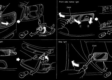
The front clearance, side marker, tail, license
plate and instrument lights will come on.
Turn the switch to the
position:
Headlights will come on and all the other lights remain on.
SIC0188
IC1284MA
Instrument brightness control The instrument brightness control operates when the light switch is in the or
position.
Turn the control to adjust the brightness of instrument panel lights (except clock) and power window switch lights. When the control is turned to the right until a click sound is heard, the light intensity will be at maximum. When the control is turned to the left until a click sound is heard, the light will be turned off.
Instruments and controls 2-17
Z 01.1.22/A32-D/V5.0 X
FRONT FOG LIGHT SWITCH (if so equipped)
When the daytime running light system is active, tail lights on your vehicle are not on. It is necessary at dusk to turn on your headlights. Failure to do so could cause an accident injuring yourself and others.
TURN SIGNAL SWITCH Turn signal Move the lever up or down to signal the turning direction. When the turn is completed, the turn signals cancel automatically. Lane change signal To indicate a lane change, move the lever up or down to the point where lights begin flash- ing.
SIC0880
position,
To turn the fog lights on, turn the headlight then turn the switch to the switch to the position. To turn them off, turn the switch to the OFF position. The headlights must be on for the fog lights to operate.
flash the
Headlight beam select To select the high beam, push the lever for- ward. Pull it back to select the low beam. Passing signal Pulling the lever toward you will headlight high beam. Daytime running light system (Canada only) The headlights automatically illuminate at a reduced intensity when the engine is started with the parking brake released. The daytime running lights operate with the headlight switch in the OFF position or in the position. Turn the headlight switch to the position for full illumination when driving at night. If the parking brake is applied before the engine is started, the daytime running lights do not illuminate. The daytime running lights illu- minate once the parking brake is released. The daytime running lights will remain on until the ignition switch is turned off.
2-18 Instruments and controls
Z 01.1.22/A32-D/V5.0 X
HAZARD WARNING FLASHER SWITCH
HORN
on the highway unless unusual cir- cumstances force you to drive so slowly that your vehicle might be- come a hazard to other traffic.
I Turn signals do not work when the
switch is operating.
The flasher can be actuated with the ignition switch either off or on.
SIC0178
Push the switch on to warn other drivers when you must stop or park under emergency con- ditions. All turn signal lights will flash. Some state laws may prohibit the use of the hazard warning flasher switch while driv- ing.
I When stalled or stopped on the road- way under emergency conditions, move the vehicle well off the road.
I Do not use the switch while moving
To sound the horn, push the center pad area of the steering wheel.
SIC0909
Instruments and controls 2-19
Z 01.1.22/A32-D/V5.0 X
should be removed immediately with a dry cloth.
I When cleaning the seat, never use benzine, thinner, or any similar mate- rials.
I If any abnormalities are found or the heated seat does not operate, turn the switch off and have the system checked by your NISSAN dealer.
HEATED SEATS (if so equipped)
SIC0693
The front seats are warmed by built-in heaters. The switches located on the center console can be operated independently of each other.
1. Start the engine.
2. Select heat range.
I For low heat, press the top of the switch. I For high heat, press the bottom of the
switch.
I For no heat, the switch has a center OFF
position between low and high.
The indicator light in the switch will illumi- nate when low or high is selected.
2-20 Instruments and controls
The heater is controlled by a thermostat, automatically turning the heater on and off. The indicator light will remain on as long as the switch is on.
3. When the vehicle’s interior is warmed, or before you leave the vehicle, be sure to turn the switch off.
I The battery could run down if the seat heater is operated while the engine is not running.
I Do not use the seat heater for ex- tended periods or when no one is using the seat.
I Do not put anything on the seat which insulates heat, such as a blanket, cushion, seat cover, etc. Otherwise, the seat may become overheated.
I Do not place anything hard or heavy on the seat or pierce it with a pin or similar object. This may result in damage to the heater.
I Any liquid spilled on the heated seat
Z 01.1.22/A32-D/V5.0 X
TRACTION CONTROL SYSTEM (TCS) CANCEL SWITCH (if so equipped)
CIGARETTE LIGHTER AND ASHTRAY
SIC1065
SIC0694
To cancel the Traction Control System (TCS), push the TCS cancel switch. The indicator will come on. Push it again to turn the
system back on. See “Traction control system” in the “5. Start- ing and driving” section.
The cigarette lighter element is an accessory. A genuine NISSAN cigarette lighter or equiva- lent can be purchased from your local NISSAN dealer. The cigarette lighter operates when the igni- tion switch is in the ACC or ON position. Push the lighter in all the way. When the lighter is heated, it will spring out. Return the lighter to its original position after use.
The cigarette lighter should not be used while driving in order that full attention may be given to the driving operation.
The cigarette lighter socket is a power source for the cigarette lighter element only. The use of the cigarette lighter socket as a power source for any other accessory is not recommended.
Instruments and controls 2-21
Z 01.1.22/A32-D/V5.0 X
STORAGE
while driving in order that full attention may be given to the driving operation.
TRAYS
SIC0181
The storage tray should not be used
2-22 Instruments and controls
Z 01.1.22/A32-D/V5.0 X
Pull the armrest forward and lay it horizontal. Then release the lever (inset) and pull the tray forward (if so equipped). In this condition you are able to gain access to the trunk room.
Properly secure all cargo to help prevent
SIC0883
it from sliding or shifting. Do not place cargo higher than the seatbacks. In a sudden stop or collision, unsecured cargo could cause personal injury.
Instruments and controls 2-23
Z 01.1.22/A32-D/V5.0 X
I Avoid abrupt starting and braking when the cup holder is being used to prevent spilling the drink. If the liquid is hot, it can scald you or your pas- senger.
I Use only soft cups in the cup holder. Hard objects can injure you in an accident.
CUP HOLDER
SIC0881
The cup holder should not be used while driving in order that full attention may be given to the driving operation.
2-24 Instruments and controls
SPA0092
GLOVE BOX When locking or unlocking the glove box, use the master key. The glove box may be opened by pulling the handle.
Keep glove box lid closed while driving to help prevent injury in an accident or a sudden stop.
Z 01.1.22/A32-D/V5.0 X
WINDOWS
Unattended children could become involved in serious accidents.
The power window only operates when the ignition key is in the ON position. To open or close the window, push down or pull up the switch and hold it. The main switch (driver side switches) will open or close all the windows.
CONSOLE BOX Card holder
SIC0882
SIC0182
POWER WINDOWS
The card holder should not be used while driving in order that full attention may be given to the driving operation.
I Make sure that all passengers have their hands, etc. inside the vehicle before closing the windows. Use the window lock switch to prevent unex- pected use of the power windows.
I Do not leave children unattended in- side the vehicle. They could unknow- ingly activate switches or controls and become trapped in a window.
Instruments and controls 2-25
Z 01.1.22/A32-D/V5.0 X
SUNROOF (if so equipped)
SIC0183
SIC0184
IC1432
The passenger side switch will open or close only the corresponding window. To open or close the window, hold the switch down or up. Locking passenger’s windows When the lock button is pushed in, only the driver side window can be opened or closed. Push it in again to cancel.
Automatic operation To fully open the driver side window, com- pletely push down the switch and release it; it need not be held. The window will automati- cally open all the way. To stop the window, just pull up the switch toward the close side. A light press on the switch will cause the window to open until the switch is released.
AUTOMATIC SUNROOF The sunroof will only operate when the ignition key is in the ON position. Sliding the sunroof To open the roof, press and hold the switch to the
side.
side.
To close the roof, press and hold the switch to the Tilting the sunroof To tilt up, first close the sunroof, then press and hold the side of the tilt switch. To tilt
2-26 Instruments and controls
Z 01.1.22/A32-D/V5.0 X
CLOCK
down the sunroof, press and hold the
side.
Sun shade Open or close the sun shade by sliding it backward or forward.
The shade will open automatically when the sunroof is opened. However, it must be closed manually.
I Do not place any heavy object on the
sunroof or surrounding area.
If the sunroof does not close Have your NISSAN dealer check and repair the sunroof.
I In an accident you could be thrown from the vehicle through an open sunroof. Always use seat belts and child restraints.
I Do not allow anyone to stand up or extend any portion of their body out of the opening while the vehicle is in motion or while the sunroof is closing.
I Remove water drops, snow,
ice or sand from the sunroof before open- ing.
SIC0910
The digital clock displays time when the igni- tion key is in ACC or ON. If the power supply is disconnected, the clock will not indicate the correct time. Readjust the time. ADJUSTING THE TIME Push the H button to adjust the hour. Push the M button to adjust the minute.
Instruments and controls 2-27
Z 01.1.22/A32-D/V5.0 X
INTERIOR LIGHT
PERSONAL LIGHT
and the driver’s door is opened and then closed.
The timer is cancelled, and the light will turn off when: I The driver’s door is locked. I The ignition switch is turned ON.
Leaving the light switch in the ON posi- tion for extended periods of time will result in a discharged battery.
IC1226
IC1019-B
CEILING The light has a three-position switch. When the switch is in the center q position, the light will illuminate when a door is opened.
The light will stay on for about 30 seconds when: I The key is removed from the ignition switch
while the driver’s door is closed.
I The driver’s door is unlocked while the key
is removed from the ignition switch.
I The key is removed from the ignition switch
2-28 Instruments and controls
Z 01.1.22/A32-D/V5.0 X
VANITY MIRROR LIGHT (if so equipped)
TRUNK LIGHT
The light illuminates when the trunk lid is opened. When the trunk lid is closed, the light will go off.
IC1163-B
SIC0186
The light on the vanity mirror will turn on when the cover on the vanity mirror is opened.
Instruments and controls 2-29
Z 01.1.22/A32-D/V5.0 X
INTEGRATED HomeLink UNIVERSAL TRANSCEIVER (if so equipped) The Integrated HomeLink Universal Trans- ceiver provides a convenient way to consoli- date the functions of up to three individual hand-held transmitters into one built-in device. Integrated HomeLink Universal Transceiver: I Will operate most Radio Frequency (RF) devices such as garage doors, gates, home and office lighting, entry door locks and security systems.
I Is powered by your vehicle’s battery. No separate batteries are required. If the vehi- cle’s battery is discharged or is discon- nected, HomeLink will retain all program- ming.
is programmed,
Once the Integrated HomeLink Universal Transceiver retain the original transmitter for future programming procedures (i.e., new vehicle purchases). Upon sale of the vehicle, the programmed Integrated HomeLink Universal Trans- ceiver buttons should be erased for secu- rity purposes. For additional information, refer to “Programming the Integrated HomeLink Universal Transceiver” later in this section.
2-30 Instruments and controls
Transceiver.
became
effective
I Do not use the Integrated HomeLink Universal Transceiver with any ga- rage door opener that lacks safety stop and reverse features as required by federal safety standards. (These standards for opener models manufactured after April 1, 1982). A garage door opener which cannot detect an object in the path of a closing garage door and then automatically stop and reverse, does not meet current federal safety standards. Using a garage door opener without these features in- creases the risk of serious injury or death.
I During programming, your garage door or gate may open or close. Make sure that people and objects are clear of the garage door or gate that you are programming.
I Your vehicle’s engine should be turned off while programming the In- tegrated Universal
HomeLink
Z 01.1.22/A32-D/V5.0 X
3. Using both hands, simultaneously push the hand-held transmitter button and the de- sired HomeLink button. Do not release the buttons until step 4 has been completed. NOTE:
Some garage door openers may require the procedures noted under “Canadian Programming”.
4. The HomeLink
indicator light will
flash, first slowly and then rapidly. When the indicator light flashes rapidly, both buttons may be released. The rapid flashing light indicates the Integrated HomeLink Univer- sal Transceiver has been successfully pro- grammed.
To program the remaining two buttons, follow steps 2 through 4. If, after repeated attempts, you do not suc- cessfully program the Integrated HomeLink Universal Transceiver to learn the signal of the hand-held transmitter, refer to “Rolling Code Programming” later in this section. CANADIAN PROGRAMMING regulations required Prior hand-held transmitters to stop transmitting af- ter 2 seconds. To program your hand-held transmitter to HomeLink , continue to press
to 1992, D.O.C.
and hold the HomeLink button (note steps 2
through 4 under “Programming HomeLink ”) while you press and re-press (“cycle”) your hand-held transmitter every 2 seconds until the indicator light flashes rapidly (indicating successful programming). NOTE:If programming a garage door opener, etc., it is advised to unplug the device during the “cycling” process to prevent possible damage to the garage door opener compo- nents. OPERATING THE INTEGRATED HomeLink UNIVERSAL TRANSCEIVER The Integrated HomeLink Universal Trans- ceiver (once programmed) may now be used to activate the garage door, etc. To operate, simply press the appropriate programmed In- tegrated HomeLink Universal Transceiver button. The red indicator light will illuminate while the signal is being transmitted. PROGRAMMING PROBLEM-DIAGNOSIS If the HomeLink does not quickly learn the hand-held transmitter information:
Instruments and controls 2-31
Z 01.1.22/A32-D/V5.0 X
SPA0609A
PROGRAMMING HomeLink 1. With the ignition key in the OFF position, press and hold the two outside buttons, and release when the indicator light begins to flash (approximately 20 seconds). This pro- cedure erases the factory set default codes and does not have to be followed when programming additional hand-held trans- mitters.
2. Hold the end of the hand-held transmitter (from the device you wish to train) approxi- mately 2 to 5 inches (50 to 127 mm) away from the surface of HomeLink keeping the indicator light in view.
I replace the hand-held transmitter batteries
with new batteries.
I position the hand-held transmitter with its from the
facing
away
battery HomeLink surface.
area
I press and hold both the HomeLink and hand-held transmitter buttons without inter- ruption.
I position the hand-held transmitter 2 to 5
inches (50 to 127 mm) away from the HomeLink surface. Hold the transmitter in that position for up to 15 seconds. If HomeLink is not programmed within that time, try holding the transmitter in another position - keeping the indicator light in view at all times.If you continue to have programming difficul- ties, please contact the NISSAN Consumer Affairs Department. The phone numbers are located in the Foreword of this Owner’s Manual. CLEARING THE PROGRAMMED INFORMATION Individual buttons cannot be cleared, however to clear all programming, press and hold the two outside buttons and release when the
2-32 Instruments and controls
indicator light begins to flash (approximately 20 seconds). ROLLING CODE PROGRAMMING Rolling code garage door openers (or other rolling code devices) which are “code pro- tected” and manufactured after 1996, may be determined by the following.
A. Reference the garage door opener Owner’s
Manual for verification.
B. The hand-held transmitter appears to pro- gram the Integrated HomeLink Universal Transceiver but does not activate the ga- rage door.
If
C. Press and hold the trained HomeLink but- ton. the garage door opener has the rolling code feature, the HomeLink indica- tor light will flash rapidly, then remains on after 2 seconds.
To program the Integrated HomeLink Univer- sal Transceiver to a garage door opener with the rolling code feature, follow these instruc- tions after completing the “Programming HomeLink ” (the aid of a second person may make the following procedures quicker and easier). 1. Locate the training button on the garage door opener motor unit. Exact location and
color of the button may vary by garage door opener brand. If there is difficulty locating the training button, reference the garage door opener Owner’s Manual.
2. Press the training button on the garage door opener motor unit (which may activate a training light). NOTE:
Following step 2, there are 30 seconds in which to initiate step 3.
3. Firmly press and release the programmed HomeLink button. Press and release the HomeLink button a second time to com- plete the training process. (Some garage door openers may require you to do this procedure a third time to complete the training.)
The garage door opener should now recognize the Integrated HomeLink Universal Trans- ceiver and activate when the HomeLink but- ton is pressed. The remaining two buttons may now be programmed (if not yet programmed, follow steps 2 through 4 in the “Programming HomeLink ” procedures earlier in this section). REPROGRAMMING A SINGLE HomeLink BUTTON To reprogram an Integrated HomeLink Uni-
Z 01.1.22/A32-D/V5.0 X
versal Transceiver button, complete the follow- ing.
1. Press and hold the desired HomeLink button. Do not release the button until step 4 has been completed.
2. When the indicator light begins to flash slowly (after 20 seconds), position the hand-held transmitter 2 to 5 inches (50 to 127 mm) away from the HomeLink sur- face.
3. Press and hold the hand-held transmitter
button.
4. The HomeLink
indicator light will
flash, first slowly and then rapidly. When the indicator light begins to flash rapidly, re- lease both buttons.
The Integrated HomeLink Universal Trans- ceiver button has now been reprogrammed. The new device can be activated by pushing the HomeLink button that was just pro- grammed. This procedure will not affect any other programmed HomeLink buttons. IF YOUR VEHICLE IS STOLEN If your vehicle is stolen, you should change the codes of any non-rolling code device that has been programmed into HomeLink . Consult the Owner’s Manual of each device or call the
manufacturer or dealer of those devices for additional information. When your vehicle is recovered, you will reprogram the need to Integrated Universal Transceiver with HomeLink your new transmitter information.
FCC Notice:
This device complies with FCC rules part 15. Operation is subject to the following two conditions: (1) This device may not cause harmful interference and (2) This device must accept any interference that may be received, including interference that may cause undesired operation. The transmitter has been tested and com- plies with FCC and DOC/MDC rules. Changes or modifications not expressly approved by the party responsible for com- pliance could void the user’s authority to operate the device. DOC: ISTC 1763K1313
FCC I.D.: CB2V67690Instruments and controls 2-33
Z 01.1.22/A32-D/V5.0 X
MEMO
2-34 Instruments and controls
Z 01.1.22/A32-D/V5.0 X
3 Pre-driving checks and adjustments
Keys .......................................................................... 3-2
Doors......................................................................... 3-3
Locking with key........................................................ 3-3
Locking with inside lock knob ................................... 3-3
Locking with power door lock switch ........................ 3-4
Child safety rear door lock........................................ 3-4
Multi-remote control system (if so equipped)............ 3-5
How to use multi-remote control system .................. 3-6
Battery replacement .................................................. 3-7
Hood.......................................................................... 3-8
Trunk lid .................................................................... 3-9Opener operation ...................................................... 3-9
Key operation .......................................................... 3-10
Fuel filler lid............................................................. 3-10
Opener operation .................................................... 3-10
Fuel filler cap........................................................... 3-11
Steering wheel ........................................................ 3-12
Tilt operation ........................................................... 3-12
Mirrors ..................................................................... 3-12
Inside mirror ............................................................ 3-12
Outside mirrors........................................................ 3-13Z 01.1.22/A32-D/V5.0 X
KEYS
SPA0658
SPA0662A
The master key can be used for all the locks. Record the key number on the key number plate and keep it in a safe place (such as your wallet), not in the car. A key number plate is supplied with your key. Keep the plate in a safe place. NISSAN does not record key numbers so it is very important to keep track of your key number plate. A key number is only necessary when you have lost all keys and do not have one to duplicate from. If you still have a key, this key can be duplicated by your NISSAN dealer or a locksmith shop.
3-2 Pre-driving checks and adjustments
Nissan Vehicle Immobilizer System KEY - Master keys (if so equipped):
You can only drive your vehicle using the master keys which are registered to the Nissan Vehicle Immobilizer System components in your vehicle. These keys have a transponder chip in the key head. Never leave these keys in the vehicle.
Record the key number on the key number plate supplied with your keys and keep it in a safe place (such as your wallet), not in the vehicle. NISSAN does not record any key number so it is very important to keep track of
your key number plate. A key number is only necessary when you have lost all keys and do not have one to duplicate from. If you still have a key, this key can be duplicated by your NISSAN dealer. The key number is necessary when you need extra Nissan Vehicle Immobilizer System keys. As many as 5 Nissan Vehicle Immobi- lizer System keys can be used with one ve- hicle. New keys must be registered to the Nissan Vehicle Immobilizer System compo- nents in your vehicle by your NISSAN dealer. At this time, you should bring all Nissan Ve- hicle Immobilizer System keys that you have to your NISSAN dealer for registration. This is because the registration process will erase all memory of the Nissan Vehicle Immobilizer System components.
Z 01.1.22/A32-D/V5.0 X
DOORS
I Always have the doors locked while driving. Along with the use of seat belts, this provides greater safety in the event of an accident by helping to prevent persons from being thrown from the vehicle. This also helps keep children and others from unintention- ally opening the doors, and will help keep out intruders.
I Before opening any door, always look
for and avoid oncoming traffic.
I Do not leave children unattended in- side the vehicle. They could unknow- ingly activate switches or controls. Unattended children could become involved in serious accidents.
SPA0084
SPA0085
LOCKING WITH KEY Power The power door lock system allows you to lock or unlock all doors simultaneously. I Turning the front door key to the front of the
vehicle will lock all doors.
I Turning the front door key one time to the rear of the vehicle will unlock the corre- sponding door. From that position, return- ing the key to neutral (where the key can only be removed and inserted) and turning it to the rear again within 5 seconds will unlock all doors.
LOCKING WITH INSIDE LOCK KNOB Power Pushing the front door inside lock knob to the lock position will lock all doors. To lock from the outside without a key, move the inside lock knob to the LOCK position. Then close the door. When locking the door this way, be certain not to leave the key inside the vehicle. The inside lock knob cannot be set to the LOCK position with the front doors open and Pre-driving checks and adjustments 3-3
Z 01.1.22/A32-D/V5.0 X
with the key in the ignition.
SPA0088
SPA0086
LOCKING WITH POWER DOOR LOCK SWITCH Operating the lock-unlock switch will unlock all doors.
lock or
CHILD SAFETY REAR DOOR LOCK Child safety locking helps prevent doors from being opened accidentally, especially when small children are in the vehicle. When the lever is in the lock position, the rear door can be opened only from the outside.
I Before opening any door, always look
for and avoid oncoming traffic.
3-4 Pre-driving checks and adjustments
Z 01.1.22/A32-D/V5.0 X
MULTI-REMOTE CONTROL SYSTEM (if so equipped)
I Do not leave children unattended in- side the vehicle. They could unknow- ingly activate switches or controls. Unattended children could become involved in serious accidents.
SPA0277
Pre-driving checks and adjustments 3-5Z 01.1.22/A32-D/V5.0 X
It is possible to lock/unlock all doors, to open the driver’s and front passenger’s windows, to release the trunk lid and to turn on or off the interior light by using the remote controller from outside the car. Be sure to remove the key from the vehicle before locking the doors and leaving it. The remote controller can operate at a dis- tance of approximately 49 ft (15 m) from the vehicle. (The effective distance depends upon the conditions around the vehicle.) As many as four remote controllers can be used with one vehicle. For information con- cerning the purchase and use of additional remote controllers, contact your NISSAN dealer.
Listed below are conditions or occur- rences which will damage the remote controller. I Do not allow the remote controller to
become wet.
I Do not drop the remote controller. I Do not strike the remote controller
sharply against another object.
I Do not place the remote controller for 3-6 Pre-driving checks and adjustments
an extended period in an area where temperatures exceed 140°F (60°C).
when the interior light switch is in the center q position.
HOW TO USE MULTI-REMOTE CONTROL SYSTEM Locking doors 1. Remove the ignition key.
2. Close all of the doors.
3. Push the controller.