- 2010 Mercedes-Benz R Class Owners Manuals
- Mercedes-Benz R Class Owners Manuals
- 2006 Mercedes-Benz R Class Owners Manuals
- Mercedes-Benz R Class Owners Manuals
- 2008 Mercedes-Benz R Class Owners Manuals
- Mercedes-Benz R Class Owners Manuals
- 2009 Mercedes-Benz R Class Owners Manuals
- Mercedes-Benz R Class Owners Manuals
- 2007 Mercedes-Benz R Class Owners Manuals
- Mercedes-Benz R Class Owners Manuals
- 2011 Mercedes-Benz R Class Owners Manuals
- Mercedes-Benz R Class Owners Manuals
- Download PDF Manual
-
RGet a jump start. To prevent accelerated vehicle battery discharge or a completely discharged vehicle battery, always remove the SmartKey from the starter switch when the engine is not in operation.
i If the SmartKey does not belong to the
vehicle, the SmartKey can be turned in the starter switch. However, the ignition does not switch on and the engine does not start.
95
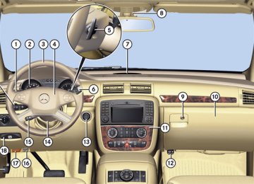
Controls in detail
page 66.
Starter switch positions KEYLESS-GO G Observe Safety notes, see Vehicles equipped with the KEYLESS-GO feature are supplied with a SmartKey with integrated KEYLESS-GO function and a removable KEYLESS-GO start/stop button. With the KEYLESS-GO start/stop button inserted in the starter switch and the SmartKey present in the vehicle, pressing the KEYLESS-GO start/stop button Rwithout the brake pedal depressed
corresponds to the various starter switch positions (Y page 95)
Rwith the brake pedal firmly depressed will
start the engine (Y page 129)
If you wish or should there be the need to insert the SmartKey in the starter switch, the KEYLESS-GO start/stop button can be easily removed by pulling it out of the starter switch. i The KEYLESS-GO start/stop button does
not need to be removed from the starter switch when you leave the vehicle. However, always take the SmartKey with you when you leave the vehicle. As long as the SmartKey is in the vehicle, the vehicle’s electrical systems can be switched on or
96
the engine can be started using the KEYLESS-GO start/stop button.
The SmartKey must be located in the vehicle.
1 KEYLESS-GO start/stop button 2 Starter switch X Insert KEYLESS-GO start/stop button 1
into starter switch 2 (if not inserted already).
X Make sure the automatic transmission is in
park position P.
X Do not depress the brake pedal.
KEYLESS-GO start/stop button 3 USA only 4 Canada only
Position 0
Before you press the KEYLESS-GO start/stop button, the vehicle’s on-board electronics have status 0 (as with SmartKey removed).Position 1
X Press the KEYLESS-GO start/stop buttononce. This supplies power for some electrical consumers, such as radio functions.
i If you now press the KEYLESS-GO start/
stop button Ronce more, the ignition (position 2) is
switched on
Rtwice more the power supply is again
switched off
Ignition (or position 2) X Press the KEYLESS-GO start/stop button
twice. This supplies power for all electrical consumers. All lamps (except high-beam headlamp indicator lamp and turn signal indicator lamps unless activated) in the instrument cluster come on. If a lamp in the instrument cluster fails to come on when the ignition is switched on, have it checked and replaced if necessary. If a lamp in the instrument cluster remains on after starting the engine or comes on while driving, refer to “Lamps in instrument cluster” (Y page 340).
i If you now press the KEYLESS-GO start/ stop button once, the power supply is again switched off.
Seats Safety notes G Warning! In order to avoid possible loss of vehicle control all seat, head restraint, steering wheel, and rear view mirror adjustments, as well as fastening of seat belts, must be done before the vehicle is put into motion. G Warning! Do not adjust the driver’s seat while driving. Adjusting the seat while driving could cause the driver to lose control of the vehicle. Never ride in a moving vehicle with the seat backrest in an excessively reclined position as this can be dangerous. You could slide under the seat belt in a collision. If you slide under it, the seat belt would apply force at the abdomen or neck. That could cause serious or fatal injuries. The seat backrest and seat belts provide the best restraint when the wearer is in a position that is as upright as possible and seat belts are properly positioned on the body.
Controls in detail
Seats
G Warning! Your seat must be adjusted so that you can correctly fasten your seat belt. Observe the following points: RAdjust the seat backrest until your arms
are slightly angled when holding the steering wheel.
RAdjust the seat to a comfortable seating position that still allows you to reach the accelerator/brake pedal safely. The position should be as far back as possible with the driver still able to operate the controls properly.
RAdjust the head restraint so that it is as
close to the head as possible and the center of the head restraint supports the back of the head at eye level.
RNever place hands under the seat or near
any moving parts while a seat is being adjusted.
Failure to do so could result in an accident and/or serious personal injury. G Warning! The power seats can be operated at any time. Therefore, do not leave children unattended in the vehicle, or with access to
97
Controls in detail
Seats an unlocked vehicle. A child’s unsupervised access to a vehicle could result in an accident and/or serious personal injury. G Warning! According to accident statistics, children are safer when properly restrained in the rear seating positions than in the front seating position. Thus, we strongly recommend that children be placed in the rear seats whenever possible. Regardless of seating position, children 12 years old and under must be seated and properly secured in an appropriately sized infant restraint, toddler restraint, or booster seat recommended for the size and weight of the child. For additional information, see “Children in the vehicle”. A child’s risk of serious or fatal injuries is significantly increased if the child restraints are not properly secured in the vehicle and/or the child is not properly secured in the child restraint. G Warning! For your protection, drive only with properly positioned head restraints. Adjust the head restraint so that it is as close to the head as possible and the center
98
of the head restraint supports the back of the head at eye level. This will reduce the potential for injury to the head and neck in the event of an accident or similar situation. Do not drive the vehicle without the seat head restraints. Head restraints are intended to help reduce injuries during an accident.
Seat adjustment ! When moving the seats, make sure there are no items in the footwell or behind the seats. Otherwise, you could damage the seats.
Power seat
1 Head restraint height (vehicles with
memory function) 2 Seat cushion tilt 3 Seat height 4 Seat backrest tilt 5 Seat fore and aft adjustment
! When the second-row seats are folded
forward, e. g. for cargo volume expansion, the front seats may not be moved to the rearmost position. Otherwise you could damage the front and second-row seats.
! When adjusting the seat backrest tilt and
head restraint height, make sure the sun visor is folded up. If the head restraint is in
the uppermost position, it could hit and damage the sun visor.
i Vehicles without memory function:
The seats can be adjusted within 5 minutes after either front door has been opened. The counter resets each time Ryou open or close a front door Ryou insert the SmartKey into the starter
switch
Ryou remove the SmartKey from the
starter switch
Ryou switch the ignition on or off Just like in vehicles with memory function, the power seats can be operated at any time when the ignition is switched on.
i The memory function (Y page 114) lets you store the settings for the seat position together with the settings for the steering wheel (electrical) and exterior rear view mirrors.
X Seat fore and aft adjustment: Press the switch forward or backward in direction of arrow 5.
X Seat backrest tilt: Press the switch
forward or backward in direction of arrow 4.
X Seat height: Press the switch up or down
in direction of arrow 3.
X Seat cushion tilt: Press the switch up or down in direction of arrow 2 until your upper legs are lightly supported.
X Head restraint height: Press the switch
up or down in direction of arrow 1.
Head restraint height adjustment, manual This feature is only available in vehicles without memory function. G Warning! For your protection, drive only with properly positioned head restraints. Adjust the head restraint so that it is as close to the head as possible and the center of the head restraint supports the back of the head at eye level. This will reduce the potential for injury to the head and neck in the event of an accident or similar situation.
Controls in detail
Seats
Do not drive the vehicle without the seat head restraints. Head restraints are intended to help reduce injuries during an accident. With a third-row seat occupied, make sure to move the respective head restraint up from the lowest non-use position and have the occupant adjust the head restraint properly.
! Do not attempt to remove front seat head
restraints. They can only be removed by qualified technicians. We recommend that you have this work carried out by an authorized Mercedes-Benz Center.
1 Head restraint 2 Release button
99
Controls in detail
Seats X Raising: Adjust the height of head restraint
1 manually by pulling it upward. If head restraint 1 is fully retracted, push release button 2 in direction of arrow and pull head restraint 1 upward.
X Lowering: Push release button 2 in
direction of arrow and press down on head restraint 1.
Head restraint fore and aft adjustment G Warning! Vehicles with Rear Seat Entertainment Package: When adjusting the head restraint, make sure your fingers do not become caught between the head restraint cushion and the monitor. Failing to do so may lead to injury.
100
X While seated, reach behind you with both
hands and find lower edge of the head restraint.
X Adjust the head restraint to the desired
position by pushing or pulling on the lower edge of the head restraint cushion.
Easy-entry/exit feature for third-row seats This feature allows for easier access to and exit from the vehicle’s third-row seats. G Warning! To help avoid personal injury, the second- row seat backrests must be properly locked either in the upright position or, when using the expanded cargo volume, in the fully folded position while the vehicle is in motion.
! 7-seat vehicles:
Do not use the driver’s side easy-entry/exit feature for third-row seats when the second-row middle seat is in armrest position. Otherwise, the seat belt outlet of the second-row middle seat could damage the seat backrest of the outboard seat.
Easy-entry feature for third-row seats The releases for the easy-entry feature are located on the entry side and the back of each outboard second-row seat.
1 Easy-entry lever X Pull and hold easy-entry lever 1 in
direction of arrow at resistance point. The seat backrest folds forward.
X Push the seat forward as far as it will go. You should now have sufficient space to access the vehicle’s third-row seat.
Controls in detail
Seats
Easy-entry/exit position X Enter the vehicle. For information on how to fold down the second-row seats completely, see “Expanding cargo volume” (Y page 209).
Easy-exit feature for third-row seats The easy-exit strap is located on the rear of each outboard second-row seat base.
1 Easy-exit strap X To exit the vehicle when seated on a third- row seat, pull up and hold easy-exit strap 1. The second-row seat backrest folds forward.
X Push second-row seat forward a far as it will
go.
Easy-entry/exit position X Exit the vehicle. For information on how to fold down the second-row seats completely, see “Expanding cargo volume” (Y page 209).
Returning outboard second-row seats to their original position G Warning! When occupants have entered or exited the vehicle using the easy-entry/exit feature, before driving off make sure
101
Controls in detail
Seats Rthe outboard second-row seats are
properly locked
Rthe seat backrests of the outboard second-row seats are in an upright position and are properly locked
An outboard second-row seat is properly locked only when lock status indicator 1
is in hinged position and red marking 2 is barely visible. If a seat and seat backrest are not properly locked, the seat could move forward and the seat backrest could fold. You could slide under the seat belt during braking, vehicle maneuvers, or in an accident. If you slide under it, the seat belt would apply force at the abdomen or neck. That could cause serious or even fatal injuries.102
Seat unlocked 1 Lock status indicator 2 Red marking When the seat is unlocked, lock status indicator 1 is extended and red marking 2 is clearly visible. X When the seat is unlocked, push seat backrest back until the seat audibly engages.
Seat locked 1 Lock status indicator 2 Red marking When the seat is locked, lock status indicator 1 is in hinged position and red marking 2
is barely visible.Lumbar support You can adjust the contour of the driver’s seat lumbar support to help enhance support to your spine.
1 Curvature up 2 Less curvature 3 Curvature down 4 Greater curvature X Curvature position: Use button 1 to move the curvature up and button 3 to move it down.
X Degree of curvature: Use button 2 to
lessen the curvature and button 4 to increase it.
Rear seats G Warning! According to accident statistics, children are safer when properly restrained in the rear seating positions than in the front seating position. Thus, we strongly recommend that children be placed in the rear seats whenever possible. Regardless of seating position, children 12 years old and under must be seated and properly secured in an appropriately sized infant restraint, toddler restraint, or booster seat recommended for the size and weight of the child. For additional information, see “Children in the vehicle”. A child’s risk of serious or fatal injuries is significantly increased if the child restraints are not properly secured in the vehicle and/or the child is not properly secured in the child restraint.
Rear seat adjustment G Warning! Never ride in a moving vehicle with the seat backrest in an excessively reclined position as this can be dangerous. You could slide
Controls in detail
Seats under the seat belt in a collision. If you slide under it, the seat belt would apply force at the abdomen or neck. That could cause serious or fatal injuries. The seat backrest and seat belts provide the best restraint when the wearer is in a nearly upright position and seat belts are properly positioned on the body. Your seat must be adjusted so that you can correctly fasten your seat belt. Never place hands under the seat or near any moving parts while a seat is being adjusted. After adjusting rear seats, make sure Rthe seats are properly locked Rthe seat backrests are in an upright
position and are properly locked
An outboard second-row seat is properly locked only when lock status indicator 1
is in hinged position and red marking 2 is barely visible. If a seat and seat backrest are not properly locked, the seat could move forward and the seat backrest could fold. You could slide under the seat belt during braking, vehicle maneuvers, or in an accident. If you slide under it, the seat belt would apply103
Controls in detail
Seats force at the abdomen or neck. That could cause serious or even fatal injuries.
Fore and aft adjustment (outboard second-row seats)
Seat backrest tilt (outboard second-row seats)
To make sure the seat backrest has engaged, lean firmly against the seat backrest.
Seat backrest tilt (third-row seats)
1 Adjustment handle X Pull up handle 1 in direction of arrow and
hold it there.
X Move seat to the desired position. X Release handle 1.
The seat must audibly engage.
1 Adjustment handle X While seated, pull handle 1 in direction of arrow to resistance point and hold it there.
X To move seat backrest back, lean lightly
against the seat backrest.
X To move seat backrest forward, lean
forward with handle 1 pulled and held at resistance point. The seat backrest will move forward against your back.
X Release handle 1 when the seat backrest
has reached the desired position.
1 Adjustment handle X While seated, pull handle 1 in direction of
arrow and hold it there.
X To move seat backrest back, lean lightly
against backrest.
X To move seat backrest forward, lean
forward with handle 1 pulled. The seat backrest will move forward against your back.
104
X Release handle 1 when the seat backrest
has reached the desired position.
X To make sure the seat backrest has
engaged, lean firmly against the backrest.
Head restraint height G Warning! With the second-row middle seat or a third- row seat occupied, make sure to move the respective head restraint up from the lowest non-use position and have the occupant adjust the head restraint properly. For your protection, drive only with properly positioned head restraints. Adjust the head restraint so that it is as close to the head as possible and the center of the head restraint supports the back of the head at eye level. This will reduce the potential for injury to the head and neck in the event of an accident or similar situation.
Outboard second-row seat head restraint 1 Head restraint 2 Release button X Raising: Manually adjust the height of head
restraint 1 by pulling it upward to the desired position.
X Lowering: Push release button 2 and
press down on head restraint 1.
i The head restraint of the second-row middle seat and the third-row seat head restraints are adjusted in the same manner.
i The tilt of the second-row head restraints is adjusted in the same manner as the front- seat head restraints, see “Head restraint adjustment” (Y page 100).
Controls in detail
Seats The tilt of the head restraint of the second- row middle seat and the third-row seat head restraints cannot be adjusted.
Head restraints, removing and installing G Warning! Do not drive the vehicle without the seat head restraints installed when the rear seats are occupied. Head restraints are intended to help reduce injuries during an accident. With the second-row middle seat or a third- row seat occupied, make sure to move the respective head restraint up from the lowest non-use position and have the occupant adjust the head restraint properly. For your protection, drive only with properly positioned head restraints. Adjust the head restraint in such a way that it is as close to the head as possible and the center of the head restraint supports the back of the head at eye level. This will reduce the potential for injury to the head and neck in the event of an accident or similar situation.
105
Controls in detail
Seats i When removing or installing the head
restraint of an outboard second-row seat, adjust the seat to the rear as far as possible (Y page 104) and fold the seat backrest (Y page 100) forward.
Seat position for removal of head restraints from outboard second-row seats 1 Head restraint 2 Release button
Removing X Pull head restraint 1 to its uppermost
position.
X Press release button 2 and pull out head
restraint 1.
106
Installing X Insert head restraint 1 into openings on
the seat backrest.
i On the outboard second-row seats, the guide bar with the detent must be on the left.
X Push head restraint 1 down until it audibly
engages.
X Push release button 2 and adjust head
restraint 1 to the desired position (Y page 105).
i The head restraint of the second-row middle seat and the third-row seat head restraints are installed in the same manner.
Armrests 6-seat vehicles The second-row seat armrests can be folded up, when loading for example, and adjusted. X Folding up: Move the armrest into a
vertical position until it engages.
X Adjusting: With the armrest folded up,
disengage the armrest by pushing it towards the rear slightly.
X Fold the armrest down to the lowest and
then to the desired position until it engages.
X To readjust the armrest to a higher
position, move armrest up to the desired position until it engages.
i To readjust the armrest to a lower
position, you must first fold up the armrest again and repeat the steps above.
7-seat vehicles You can use the seat backrest of the second- row middle seat as an armrest for the outboard seats. G Warning! The folded second-row middle seat is intended to serve as an armrest only. Do not fold the second-row middle seat and allow occupants to use the folded second- row middle seat as a footrest while driving. All vehicle occupants must keep both feet on the floor in front of their seat. Otherwise, occupants could slide under the seat belt in a collision. If occupants slide under it, the belt would apply force at the abdomen or neck. That could cause serious or even fatal injuries.
Do not fold the second-row middle seat and allow occupants to use the folded second- row middle seat as a table while driving. Objects placed on the folded second-row middle seat may move freely during braking, vehicle maneuvers, or an accident and be thrown around in the vehicle interior. Objects thrown around in the vehicle interior may cause an accident and/or serious personal injury.
X Before folding the seat, completely lower
the head restraint of the second-row middle seat (Y page 105).
Armrest position
Multicontour seat The multicontour seat has a movable seat cushion and inflatable air cushions built into the seat backrest to provide additional lumbar and side support.
Controls in detail
Seats
X Switch on the ignition. X Seat cushion depth: Adjust the seat
cushion depth to the length of your upper leg using switch 1.
X Seat backrest contour: Adjust the
contour of the seat backrest to the desired position using + or -.
X Move the seat backrest support cushion to the bottom with button 4 or to the center with button 3.
X Seat backrest side bolsters: Adjust the
side bolsters so that they provide good lateral support using switch 2.
1 Seat backrest release strap 2 Seat backrest 3 Seat cushion X Pull seat backrest release strap 1 in
direction of arrow.
X Completely fold seat backrest 2 forward so that it rests on seat cushion 3 (armrest position).
1 Seat cushion depth 2 Seat backrest side bolster 3 Seat backrest center 4 Seat backrest bottom
107
Controls in detail
Multifunction steering wheel Seat heating
1 Front seat heating switch 2 Indicator lamps The switches for the outboard second-row seat heating are located in the rear center console.
1 Rear seat heating switch
108
2 Indicator lamps The red indicator lamps in the switch come on to show which heating level you have selected. The seat heating switches from level 3 (high) to level 2 after approximately 5 minutes. The seat heating switches from level 2 to level 1 (low) after approximately 10 minutes. The seat heating automatically switches off after approximately 20 minutes. X Switch on the ignition. X Switching on: Press switch 1.
Three red indicator lamps 2 in the switch come on.
X Continue pressing switch 1 until desired
seat heating level is reached.
X Switching off: Press switch 1 repeatedly
until all indicator lamps 2 go out.
If one or more of the indicator lamps 2 in the seat heating switch 1 are flashing, there is insufficient voltage available since too many electrical consumers are turned on. The seat heating switches off automatically. The seat heating will switch back on again automatically as soon as sufficient voltage is available.
Multifunction steering wheel Safety notes G Warning! Do not adjust the steering wheel while driving. Adjusting the steering wheel while driving, or driving without the steering wheel adjustment feature locked could cause the driver to lose control of the vehicle. The electrical steering wheel adjustment feature can be operated at any time. Therefore, do not leave children unattended in the vehicle, or with access to an unlocked vehicle. A child’s unsupervised access to a vehicle could result in an accident and/or serious personal injury. Make sure Ryou can reach the steering wheel with your
arms slightly bent at the elbows
Ryou can move your legs freely Rall displays (including malfunction and
indicator lamps) on the instrument cluster are clearly visible
Steering wheel adjustment, manual
Steering wheel adjustment, electrical
1 Release handle X Unlocking: Pull release handle 1 out to
its stop limit.
X Move steering wheel to the desired
position.
X Locking: Push release handle 1 back to
its original position.
X Make sure the steering wheel is securely locked by trying to move it up and down as well as in and out before driving off.
1 Adjusting steering wheel, in or out 2 Adjusting steering wheel, up or down X Adjusting steering wheel in or out: Move
stalk in direction of arrows 1.
X Adjusting steering wheel up or down:
Move stalk in direction of arrows 2.
i The memory function (Y page 114) lets
you store the settings for the steering wheel together with the settings for the seat position and the exterior rear view mirrors.
Controls in detail
Multifunction steering wheel
Easy-entry/exit feature This feature allows the driver an easier entry into and exit from the vehicle. When entering and exiting the vehicle, the steering wheel is in its uppermost position. The easy-entry/exit feature can be activated or deactivated in the Comfort submenu of the control system (Y page 158). G Warning! You must make sure no one can become trapped or injured by the moving steering wheel when the easy-entry/exit feature is activated. To stop steering wheel movement do one of the following: RMove steering wheel adjustment stalk. RPress one of the memory position
buttons.
RPress memory button M. Do not leave children unattended in the vehicle, or with access to an unlocked vehicle. Children could open the driver’s door and unintentionally activate the easy- entry/exit feature, which could result in an accident and/or serious personal injury.
109
Controls in detail
Multifunction steering wheel With the easy-entry/exit feature activated, the steering wheel will return to its last set position when you close the driver’s door with the ignition switched on. The steering wheel will also return to its last set position when you insert the SmartKey into the starter switch or press the KEYLESS-GO start/stop button once with the driver’s door closed. i The last set steering wheel position is
stored when the ignition is switched off or the position is stored in memory (Y page 114).
With the easy-entry/exit feature activated, the steering wheel tilts upwards when you remove the SmartKey from the starter switch. The steering wheel also tilts upwards when you open the driver’s door with the SmartKey in starter switch position 0 or 1 or the KEYLESS-GO start/stop button in position 1. i When the current position for the steering wheel is in the uppermost tilt position, the steering wheel will no longer be able to move upward when the easy-entry/exit feature is activated. The adjustment procedure is briefly interrupted when the engine is started.
110
G Warning! Let the system complete the adjustment procedure before setting the vehicle in motion. All steering wheel adjustment must be completed before setting the vehicle in motion. Driving off with the steering wheel still adjusting could cause the driver to lose control of the vehicle.
Heated steering wheel The steering wheel heating warms up the leather area of the steering wheel.
1 Switching on 2 Switching off 3 Indicator lamp
X Switch on the ignition. X Switching on: Turn switch at the tip of the
stalk in direction of arrow 1. Indicator lamp 3 comes on.
i The steering wheel heating may be
suspended temporarily. However, indicator lamp 3 remains on. The steering wheel heating is suspended when the temperature of the vehicle interior is above 86‡ (30†). It is also suspended when the temperature of the steering wheel is above 95‡ (35†). When these conditions do not apply anymore, steering wheel heating continues.
X Switching off: Turn switch at the tip of
stalk in direction of arrow 2. Indicator lamp 3 goes out.
i Indicator lamp 3 flashes or goes out in case of power surge or undervoltage or if the steering wheel heating malfunctions.
i The steering wheel heating switches off
automatically when you remove the SmartKey from the starter switch or, on vehicles with KEYLESS-GO, when you
switch off the ignition and open the driver’s door.
For more information on the steering wheel, see “Multifunction steering wheel” (Y page 145).
Mirrors Notes Adjust the interior and exterior rear view mirrors before driving so that you have a good view of the road and traffic conditions.
Interior rear view mirror X Adjust the interior rear view mirror
manually.
For more information, see “Auto-dimming rear view mirrors” (Y page 112).
Interior rear view mirror, antiglare position
Controls in detail
Mirrors X Tilt the mirror to the antiglare position by moving lever 1 towards the windshield. The interior rear view mirror is dimmed.
Exterior rear view mirrors G Warning! Exercise care when using the passenger- side exterior rear view mirror. The mirror surface is convex (outwardly curved surface for a wider field of view). Objects in mirror are closer than they appear. Check your interior rear view mirror and glance over your shoulder before changing lanes.
1 Lever
111
Controls in detail
Mirrors
1 Driver’s side exterior rear view mirror
button
2 Adjustment button 3 Passenger-side exterior rear view mirror
button
X Switch on the ignition. X Press button 1 for the driver’s side
exterior rear view mirror or button 3 for the passenger-side exterior rear view mirror. The indicator lamp in the respective button comes on for approximately 15 seconds. If you do not make adjustments to the selected exterior rear view mirror within 15 seconds, the indicator lamp goes out. You will then have to select the desired exterior rear view mirror again before adjustments can be made. Adjustments
112
can only be made with the indicator lamp for the respective exterior rear view mirror button illuminated.
X Press adjustment button 2 up, down, left
or right according to the desired setting.
! If an exterior rear view mirror was forcibly
hit from the front, manually snap it back into place.
! Vehicle with power folding exterior rear
view mirrors: If an exterior rear view mirror housing is forcibly pushed forward (hit from the rear) or forcibly pushed rearward (hit from front), press fold button to fold mirrors in, then press fold button again to fold mirrors out. Do not force mirrors by hand as this may damage the adjustment mechanism. The mirror housing is then properly positioned and you can adjust the mirror in the usual manner.
i At low ambient temperatures, the exterior
rear view mirrors will be heated automatically.
Auto-dimming rear view mirrors The exterior rear view mirror on the driver’s side and the interior rear view mirror will respond automatically to glare when the ignition is switched on and incoming light from headlamps falls on the sensor in the interior rear view mirror. The rear view mirrors will not react if the automatic transmission is set to reverse gear R or the interior lighting is switched on. G Warning! The auto-dimming function does not react if incoming light is not aimed directly at sensors in the interior rear view mirror. The interior rear view mirror and the exterior rear view mirror on the driver’s side do not react, for example, when transporting cargo which covers the rear window. Light hitting the mirror(s) at certain angles (incident light) could blind you. As a result, you may not be able to observe traffic conditions and could cause an accident.
Power folding exterior rear view mirrors ! Before you drive the vehicle through an automatic car wash, fold in the exterior rear view mirrors. Otherwise they may get damaged.
Folding in and out automatically When the corresponding function in the control system is activated (Y page 159): RThe exterior rear view mirrors fold in
automatically as soon as the vehicle is locked from the outside.
RThe exterior rear view mirrors fold out automatically as soon as the vehicle is unlocked and the driver’s or front passenger door are subsequently opened.
Synchronizing The power folding rear view mirrors may have to be synchronized after the vehicle battery has been disconnected or discharged. If the exterior rear view mirrors do not fold properly upon locking or unlocking the vehicle although the corresponding function in the control system is activated (Y page 159), do the following:
X Fold each exterior rear view mirror in
completely (Y page 113).
X Fold each exterior rear view mirror out
completely (Y page 113).
When the exterior rear view mirrors fold properly upon locking the vehicle, the exterior mirrors are synchronized. Otherwise repeat the above steps.
Folding in and out manually The exterior rear view mirrors can vibrate if they are not folded out completely.
1 Button for folding exterior rear view
mirrors in and out
Controls in detail
Mirrors
X Switch on the ignition. X Folding in: Briefly press button 1.
Both exterior rear view mirrors fold in.
i If you are driving at more than
approximately 30 mph (47 km/h), you will not be able to fold the exterior mirrors in.
X Folding out: Briefly press button 1.
Both exterior rear view mirrors fold out.
! If an exterior rear view mirror housing is forcibly pushed forward (hit from the rear) or forcibly pushed rearward (hit from the front), press button 1 to fold mirrors in, then press button 1 again to fold mirrors out. Do not force mirrors by hand as this may damage the adjustment mechanism. The mirror housing is then properly positioned and you can adjust the mirror in the usual manner. Please make sure both rear view mirrors are folded out before driving off.
113
Recalling positions from memory X Press and hold desired memory position
button 1, 2 or 3 until the seat has completely moved to the stored position. On the driver’s side, also wait for the steering wheel and exterior rear view mirrors to move to the stored position.
i Releasing the memory position button stops movement to the stored positions immediately.
Controls in detail
Memory function Memory function Notes With the memory function you can store up to three different configurations per front seat. Each memory position button on the driver’s side can store all of the following settings: RSeat position RMulticontour seat: previously saved setting RSteering wheel position RExterior rear view mirrors’ position G Warning! Do not activate the memory function while driving. Activating the memory function while driving could cause the driver to lose control of the vehicle. Each memory position button on the front passenger side can store all of the following settings: RSeat position RMulticontour seat: previously saved setting
114
Memory button
1, 2, 3 Memory position button
Storing positions into memory X Adjust the seats. X On the driver’s side, additionally adjust the
steering wheel and exterior rear view mirrors to the desired positions.
X Press memory button M. X Release memory button M and press
memory position button 1, 2 or 3 within 3 seconds. When the settings are stored to the selected position, an acknowledgement signal sounds.
Lighting Notes i If you drive in countries where vehicles
drive on the other side of the road than the country where the vehicle is registered, you must have the headlamps modified for symmetrical low beams. Relevant information can be obtained at any authorized Mercedes-Benz Center.
i Vehicles equipped with active Bi-Xenon
headlamps: The active Bi-Xenon headlamps monitor the vehicle’s steering angle and speed, then automatically shift their beams to either side to better follow the curvature of the road ahead, increasing usable illumination over conventional headlamps.
Exterior lamp switch
$ a Standing lamps, left % g Standing lamps, right & M Off
Daytime running lamp mode ( U Automatic headlamp mode Daytime running lamp mode
) C Parking lamps (also tail lamps,
license plate lamps, side marker lamps and instrument panel lamps) * B Low-beam headlamps or high-beam
headlamps
, ¥ Front fog lamps . † Rear fog lamp
i The exterior lamps go out automatically when you remove the SmartKey from the
Controls in detail
Lighting starter switch or open the driver’s door with the ignition switched off. When the parking lamps or the rear fog lamp are switched on and you remove the SmartKey from the starter switch or open the driver’s door, an acoustic signal sounds. In addition the message Switch Off Lights appears in the multifunction display. Switch off the parking lamps or the rear fog lamp manually.
! Failure to switch off the parking lamps when leaving the vehicle may result in a discharged battery.
Low-beam headlamps The low-beam headlamps can be switched on and off with the exterior lamp switch. X Switch on the ignition. X Switching on: Turn the exterior lamp
switch to position B. The following lamps come on: RLow-beam headlamps RTail lamps RParking lamps
115
Controls in detail
Lighting
RLicense plate lamps RSide marker lamps RInstrument panel lamps RGreen indicator lamp C in the exterior
lamp switch
X Switching off: Turn the exterior lamp
switch to position M.
Automatic headlamp mode The following lamps come on and go out automatically depending on the brightness of the ambient light: RLow-beam headlamps RTail lamps RParking lamps RLicense plate lamps RSide marker lamps G Warning! If the exterior lamp switch is set to U, the headlamps will not automatically come on under foggy conditions. To minimize risk to you and to others, activate headlamps by turning exterior lamp switch to B when driving or when
116
traffic and/or ambient lighting conditions require you to do so. In low ambient lighting conditions, only switch from position U to B with the vehicle at a standstill in a safe location. Switching from U to B will briefly switch off the headlamps. Doing so while driving in low ambient lighting conditions may result in an accident. The automatic headlamp feature is only an aid to the driver. The driver is responsible for the operation of the vehicle’s lights at all times.
X Switching on: Turn the exterior lamp
switch to position U. With the SmartKey in starter switch position 1 or the KEYLESS-GO start/stop button pressed once, the tail and parking lamps, the license plate lamps and the side marker lamps will come on and go out depending on the brightness of the ambient light. When the engine is running the low-beam headlamps, the tail and parking lamps, the license plate lamps and the side marker lamps will come on and go out depending on the brightness of the ambient light.
Canada only: High-beam headlamps are only available with the exterior lamp switch in position B.
Daytime running lamp mode In Canada, the daytime running lamp mode is mandatory and therefore in a constant mode. In the USA, the daytime running lamp mode is deactivated by default. Activate the daytime running lamp mode using the control system, see “Setting daytime running lamp mode (USA only)” (Y page 156). X Turn the exterior lamp switch to position
M or U. When the engine is running, the low-beam headlamps come on. In low ambient lighting conditions, the following lamps will come on additionally: RTail lamps RParking lamps RLicense plate lamps RSide marker lamps
With the daytime running lamp mode activated and the engine running, you cannot switch off the low-beam headlamps manually.
Canada only With the exterior lamp switch in position M or U, you cannot switch on the high- beam headlamps. The high-beam flasher is available at all times. For nighttime driving turn the exterior lamp switch to position B to permit activation of the high-beam headlamps. When the engine is running, and you Rshift from a driving position to neutral position N or park position P with the vehicle at a standstill, the low-beam headlamps will go out with a delay of 3
minutesRturn the exterior lamp switch to position C, the low-beam headlamps, the tail and parking lamps, the license plate lamps and the side marker lamps come on
Rturn the exterior lamp switch to position
B, the manual headlamp mode has priority over the daytime running lamp mode The corresponding exterior lamps come on (Y page 115).
USA only With the exterior lamp switch in position M, you cannot switch on the high-beam headlamps. The high-beam flasher is available at all times. For nighttime driving turn the exterior lamp switch to position B or U to permit activation of the high-beam headlamps. When the engine is running, and you turn the exterior lamp switch to position C or B, the manual headlamp mode has priority over the daytime running lamp mode. The corresponding exterior lamps come on (Y page 115).
Fog lamps Fog lamps cannot be switched on with the exterior lamp switch in position U. To switch on the fog lamps, turn the exterior lamp switch to position B first. G Warning! In low ambient lighting or foggy conditions, only switch from position U to B with the vehicle at a standstill in a safe location.
Controls in detail
Lighting
Switching from U to B will briefly switch off the headlamps. Doing so while driving in low ambient lighting conditions may result in an accident. Fog lamps will operate with the parking lamps and/or the low-beam headlamps on. Fog lamps should only be used in conjunction with low-beam headlamps. Consult your State or Province Motor Vehicle Regulations regarding permissible lamp operation. X Switch on the ignition. X Turn the exterior lamp switch to position
C or B (Y page 115).
X Switching on front fog lamps: Pull out the
exterior lamp switch to first stop. The green indicator lamp ¥ in the exterior lamp switch comes on.
X Switching on rear fog lamp: Pull out the
exterior lamp switch to second stop. The rear fog lamp, the front fog lamps and the yellow indicator lamp † in the exterior lamp switch come on.
X Switching off front fog lamps/rear fog lamp: Push in the exterior lamp switch to its stop.
117
Controls in detail
Lighting Locator lighting and night security illumination Locator lighting and night security illumination are described in the “Control system” section, see “Setting locator lighting” (Y page 156) and “Setting night security illumination (Headlamps delayed shut-off feature)” (Y page 157).
Combination switch
1 High beam 2 High-beam flasher
118
High beam X Turn the exterior lamp switch to position
B (Y page 115).
Turn signals
X Switching on: Push the combination
switch in direction of arrow 1. The high-beam headlamp indicator lamp A in the instrument cluster comes on. X Switching off: Pull the combination switch
in direction of arrow 2 to its original position.
High-beam flasher X Switching on: Pull the combination switch
briefly in direction of arrow 2.
1 Turn signals, right 2 Turn signals, left X Press the combination switch in direction
of arrow 1 or 2. The corresponding turn signal indicator lamp L or K in the instrument cluster flashes.
The combination switch resets automatically after major steering wheel movements. i To signal minor directional changes such
as changing lanes, press combination switch only to point of resistance and release. The corresponding turn signal lamps will flash three times.
Hazard warning flasher The hazard warning flasher can be switched on at all times, even with the SmartKey removed from the starter switch. The hazard warning flasher comes on automatically when an air bag deploys.
1 Hazard warning flasher switch X Switching on: Press hazard warning
flasher switch 1. All turn signal lamps are flashing.
i With the hazard warning flasher activated and the combination switch set for either left or right turn, only the respective left or
right turn signals will operate when the ignition is switched on.
X Switching off: Press hazard warning
flasher switch 1 again.
i If the hazard warning flasher has been
activated automatically, press hazard warning flasher switch 1 once to switch off.
Headlamp cleaning system The headlamps will be cleaned with a high- pressure water jet automatically when the engine is running and you have Rswitched on the headlamps
and
Rthe windshield wipers have wiped the windshield with washer fluid five times
The counter resets when you switch off the headlamps. For information on filling up the washer reservoir, see “Washer system and headlamp cleaning system” (Y page 251).
Controls in detail
Lighting
Corner-illuminating front fog lamps The corner-illuminating front fog lamps improve illumination of the area in the direction into which you are turning. The corner-illuminating front fog lamps will only operate Rin low ambient lighting conditions Rat vehicle speeds below 25 mph
(40 km/h)
Rwith the front fog lamps switched off Rwith the engine is running
Switching on X Turn the exterior lamp switch to position
B or U.
or X Activate the daytime running lamp mode
(Y page 116).
X Switch on the left or right turn signal,
depending on whether you are turning left or right. The respective front fog lamp comes on. If you have switched on the turn signal for one side but turn the steering wheel in the other direction, the corner-illuminating
119
Controls in detail
Lighting
front fog lamp comes on on the side of the turn signal.
or X Turn steering wheel in the desired
direction. Driving forward: The front fog lamp on the side of your steering direction comes on. Driving in reverse: The front fog lamp opposite to your steering direction comes on.
The corner-illuminating front fog lamps will come on automatically depending on the steering angle, even if you did not switch on either turn signal. If the corner-illuminating front fog lamps came on automatically, they will also go out automatically depending on the steering angle and vehicle speed. The corner-illuminating front fog lamps temporarily come on on both sides of the vehicle if you turn the steering wheel in one direction and then again in the other direction shortly thereafter. The corner-illuminating front fog lamp remains lit for a maximum of 3 minutes. Afterward, it goes out even if the turn signal is still switched on.
120
Interior lighting in the front
Switching off X Switch off the left or right turn signal. or X Steer straight ahead.
i There may be a brief delay before the
corner-illuminating front fog lamps go out.
1 X Left front reading lamp on/off 2 ò Rear interior lighting on/off 3 ] Automatic control on/off 4 ð Front interior lighting on/off 5 X Right front reading lamp on/off 6 Front interior lighting 7 Front reading lamps 8 Front interior lighting
Automatic control X Activating: Press button ].
Button ] disengages and sits flush with the other buttons. The interior lighting and the locator lighting (Y page 156) come on in darkness, when you: Runlock the vehicle Rremove the SmartKey from the starter
switch
Ropen a door Ropen the tailgate
X Deactivating: Press button ].
Button ] engages.
The interior lighting goes out after a preset time (Y page 158). i If a door remains open, the interior lamps
go out automatically after approximately 5 minutes when the SmartKey is removed or in starter switch position 0.
Manual control ! An interior lamp switched on manually
does not go out automatically.
Leaving an interior lamp switch in the ON position for extended periods of time with the engine turned off could result in a discharged battery.
X Switching on/off front interior
lighting: Press switch ð.
X Switching on/off rear interior lighting:
Press switch ò.
X Switching on/off front reading lamps:
Press respective switch X.
Emergency lighting When the interior lighting is set to automatic mode, the interior lighting is activated automatically if the vehicle is involved in an accident. X Switching off: Press button ]. or X Press hazard warning flasher switch
(Y page 119).
or X Unlock the vehicle.
Controls in detail
Lighting
Interior lighting in the rear ! An interior lamp switched on manually
does not go out automatically. Leaving an interior lamp switch in the ON position for extended periods of time with the engine turned off could result in a discharged battery.
Second-row reading lamps The second-row reading lamps are located above the rear door windows.
1 Second-row reading lamp X Switching on/off rear reading lamps:
Press second-row reading lamp 1 as indicated by the arrow.
121
Controls in detail
Wipers Third-row reading lamps The third-row reading lamps are located in the rear overhead control panel.
Wipers Notes ! Do not operate the wipers when the
windshield/rear window is dry. Dust that accumulates on a windshield/rear window might scratch the glass and/or damage the wiper blades when wiping occurs on a dry windshield/rear window. If it is necessary to operate the wipers in dry weather conditions, always operate the wipers with washer fluid.
1 X Right third-row reading lamp on/off 2 X Left third-row reading lamp on/off 3 Left third-row reading lamp 4 Rear interior lighting 5 Right third-row reading lamp X Switching on/off third-row reading lamps: Press respective reading lamp switch X.
i The rear interior lighting is switched on
and off using the button on the front overhead control panel (Y page 120).
122
Combination switch 1 Single wipe
Wiping with washer fluid
2 Switching on windshield wipers X Switch on the ignition.
Windshield wipers
Switching on/off
M Windshield wipers off
U Slow intermittent wiping
Rain sensor operation with low sensitivity.
V Fast intermittent wiping
Rain sensor operation with high sensitivity.
u Slow continuous wiping
t Fast continuous wiping
X Turn the combination switch in direction of
arrow 2 to the desired position, depending on the intensity of the rain.
Intermittent wiping Only switch on intermittent wiping under wet weather conditions or in the presence of precipitation. When you select intermittent wiping, the rain sensor is activated. The rain sensor sets a
suitable wiping interval depending on the wetness of the sensor surface automatically. ! Do not leave windshield wipers on an intermittent setting when the vehicle is taken to an automatic car wash or during windshield cleaning. Windshield wipers will operate in the presence of water sprayed on the windshield, and windshield wipers may be damaged as a result.
! If you have set intermittent wiping, dirt on
the surface of the rain sensor or optical effects may cause the windshield wipers to wipe in an undesired fashion. This could then damage the windshield wiper blades or scratch the windshield. You should therefore switch off the windshield wipers when weather conditions are dry.
X Turn the combination switch to position
U or V. After the initial wipe, pauses between wipes are controlled by the rain sensor automatically.
Intermittent wiping is interrupted when the vehicle is at a standstill and a front door is opened. This protects persons getting into or out of the vehicle from being sprayed.
Intermittent wiping will be continued when all doors are closed and Rthe automatic transmission is in drive
position D or reverse gear R or
Rthe wiper setting is changed using the
combination switch
Single wipe X Press the combination switch briefly in direction of arrow 1 to the resistance point. The windshield wipers wipe one time without washer fluid.
Wiping with washer fluid X Press the combination switch in direction
of arrow 1 past the resistance point. The windshield wipers operate with washer fluid.
i To prevent smears on the windshield or noisy/chattering wiper blades, wipe with washer fluid every now and then even when it is raining.
Controls in detail
Wipers
For information on filling up the washer reservoir, see “Washer system and headlamp cleaning system” (Y page 251). For information on cleaning the headlamps with washer fluid, see “Headlamp cleaning system” (Y page 119).
Rear window wiper/washer
Combination switch 1 Rear window wiper switch % Wiping rear window with washer fluid & Intermittent wiping ( Rear window wiper off ) Wiping rear window with washer fluid
123
before attempting to remove any blockage.
RRemove blockage. RTurn the windshield wipers on again. If the windshield wipers fail to function at all with the combination switch in position U or V, Rset the combination switch to the next
higher wiper speed
Rhave the windshield wipers checked at the nearest authorized Mercedes-Benz Center
Controls in detail
Wipers
6 Rear window wiper indicator X Switch on the ignition. The rear window wiper engages automatically when the automatic transmission is shifted into reverse gear R with the windshield wipers switched on. X Activating intermittent wiping: Turn rear
window wiper switch 1 to position &. In the lower multifunction display you will see rear window wiper indicator 6, indicating that the rear window wiper is activated.
X Deactivating intermittent wiping: Turn rear window wiper switch 1 to position (. Indicator 6 for the rear window wiper is cleared from the lower multifunction
124
display, indicating that the rear window wiper is deactivated.
X Wiping with washer fluid: Turn and hold
rear window wiper switch 1 in position % or ) until the rear window is clean.
For information on filling up the washer reservoir, see “Washer system and headlamp cleaning system” (Y page 251).
Problems with wipers ! If anything blocks the windshield wipers
(leaves, snow, etc.), switch them off immediately. For safety reasons, stop the vehicle in a safe location, and R-
remove the SmartKey from the starter switch or turn off the engine by pressing the KEYLESS-GO start/stop button and open the driver’s door (with the driver’s door open, starter switch is in position 0, same as with SmartKey removed from starter switch)
- engage the parking brake
Power windows Opening and closing The door windows and the hinged quarter windows are opened and closed electrically. The switches for all door windows and the hinged quarter windows are located on the driver’s door control panel. The switches for the respective door windows are located on the front passenger door and the rear doors. The hinged quarter windows can be operated from the driver’s seat only. i Operating the rear door windows from the rear is not possible when you activate the override switch (Y page 74).
Vehicles equipped with the PRE-SAFE® system: If the vehicle is in a severe skid or is spinning, the door windows close until only a small gap remains. G Warning! When opening or closing the windows, make sure there is no danger of anyone being harmed by the opening/closing procedure. The door windows are equipped with the express operation and automatic reversal function. If in express operation mode a
door window encounters an obstruction that blocks its path, the automatic reversal function will stop the door window and open it slightly. The door windows operate differently when the switch is pressed and held. See the “Closing when a door window is blocked” section in this chapter for details. The closing of a door window can be immediately halted by releasing the switch or, if the switch was pulled past the resistance point and released, by either pressing or pulling the respective switch. The closing of the hinged quarter windows can be immediately halted by pressing or pulling the switch. If a window encounters an obstruction that blocks its path in a circumstance where you are closing the windows by pressing and holding button j on the SmartKey or by pressing and holding the lock button (vehicles with KEYLESS-GO) on an outside door handle, the automatic reversal function will not operate. Activate the override switch when children are riding in the back seats of the vehicle. The children may otherwise injure
Controls in detail
Power windows
themselves, e.g. by becoming trapped in the window opening. G Observe Safety notes, see page 66. G Warning! Do not keep any part of your body up against the window pane when opening a window. The downward motion of the pane may pull that part of your body down between the window pane and the door frame and trap it there. If there is a risk of entrapment, release the switch and pull it to close the window.
i You can also open or close the windows using the SmartKey, see “Summer opening feature” (Y page 127) and “Convenience closing feature” (Y page 128).
i After switching off the ignition or
removing the SmartKey from the starter switch, you can operate the windows until you open the driver’s or front passenger door. If no door was opened you can operate the windows for up to 5 minutes.
125
Controls in detail
Power windows
1 Left front door window 2 Right front door window 3 Right rear door window 4 Left rear door window 5 Hinged quarter windows
Door windows X Switch on the ignition. X Opening/Closing: Press or pull and hold switch 1 to 4 to the resistance point. The corresponding window will move downwards or upwards until you release the switch.
126
X Express operation: Press or pull switch
1 to 4 past the resistance point and release. The corresponding window opens or closes completely.
X Stopping during express operation:
Press or pull the respective switch again.
Closing when a door window is blocked G Warning! Make sure that nobody can become trapped and be seriously or even fatally injured when closing a door window with greater force or without automatic reversal function.
If the upward movement of a door window is blocked during the closing procedure, the door window will stop and open slightly. However, the door window will exert greater force before reversing than when the door window is closed in express operation. Please exercise caution! X Immediately after the door window has
stopped because it was blocked, pull the respective switch upwards until the door window is fully closed.
If the door window is blocked again and opens slightly: X Immediately after the door window was
blocked, pull the respective switch upwards until the door window is fully closed. G Warning! Pressing and holding the switch to close the door window immediately after it had been blocked two times will cause the door window to close without any reversal function for as long as you hold the switch.
Hinged quarter windows X Switch on the ignition. X Opening: Press switch 5 and release.
Both hinged quarter windows open completely.
X Closing: Pull switch 5 and release. Both hinged quarter windows close completely.
i When the obstruction sensor detects that a hinged quarter windows is blocked during
the closing process, they will stop and open slightly.
X Halting closing process: Press or pull switch 5 once more during the closing process. The hinged quarter windows will stop and open completely.
i For your safety, the hinged quarter
windows cannot be opened again until 4 seconds have passed.
Synchronizing door windows The door windows must be synchronized after the battery has been disconnected or if the door windows cannot be fully closed (express operation). Each door window must be synchronized separately. X Close all doors. X Switch on the ignition. X Pull and hold switch 1, 2, 3 or 4
(Y page 126) until the respective door window is closed. The door window opens again slightly.X Pull and hold the respective switch once
more immediately until the door window is completely closed.
X Hold the respective switch for
approximately 1 second. The door window is synchronized.
Summer opening feature If the weather is warm, you can ventilate the vehicle before driving off by simultaneously: Ropening the door windows Ropening the hinged quarter windows Ropening the tilt/sliding sunroof Ropening the panorama roof The “Summer opening” feature can only be activated via the remote control of the SmartKey. The SmartKey must be in close proximity to the driver’s outside door handle. X Aim transmitter eye of the SmartKey at the
driver’s outside door handle.
Vehicles without panorama roof X Press and hold button k on the
SmartKey until the windows and the tilt/
Controls in detail
Power windows sliding sunroof have reached the desired position. The vehicle unlocks.
X Release button k on the SmartKey to
interrupt the opening procedure.
Vehicles with panorama roof When roller sunblinds are closed: X Press and hold button k on the
SmartKey. The vehicle unlocks. The windows open and the roller sunblinds begin to retract after approximately 1 second.
X With the windows opened and the roller sunblinds fully retracted, press and hold button k on the SmartKey again. The tilt/sliding panel opens.
X Release button k on the SmartKey to
interrupt the opening procedure.
When roller sunblinds are open: X Press and hold button k on the
SmartKey. The vehicle unlocks.
127
Controls in detail
Power windows
The windows and the tilt/sliding panel opens after approximately 1 second.
X Release button k on the SmartKey to
interrupt the opening procedure.
Convenience closing feature When locking the vehicle, you can simultaneously close Rthe door windows Rthe hinged quarter windows Rthe tilt/sliding sunroof Rthe panorama roof Afterward, you can extend the roller sunblinds of the panorama roof.