- 2012 Mercedes-Benz G Class Owners Manuals
- Mercedes-Benz G Class Owners Manuals
- 2005 Mercedes-Benz G Class Owners Manuals
- Mercedes-Benz G Class Owners Manuals
- 2013 Mercedes-Benz G Class Owners Manuals
- Mercedes-Benz G Class Owners Manuals
- 2009 Mercedes-Benz G Class Owners Manuals
- Mercedes-Benz G Class Owners Manuals
- 2003 Mercedes-Benz G Class Owners Manuals
- Mercedes-Benz G Class Owners Manuals
- 2004 Mercedes-Benz G Class Owners Manuals
- Mercedes-Benz G Class Owners Manuals
- 2011 Mercedes-Benz G Class Owners Manuals
- Mercedes-Benz G Class Owners Manuals
- 2002 Mercedes-Benz G Class Owners Manuals
- Mercedes-Benz G Class Owners Manuals
- 2007 Mercedes-Benz G Class Owners Manuals
- Mercedes-Benz G Class Owners Manuals
- Download PDF Manual
-
Operation Driving instructions
앫 Comply with the warnings
(컄 page 253) and rules for off-road driving (컄 page 253).
앫 Switch off the exterior lamps as well as
the climate control.
앫 Select gear range 2 or 1 on the auto-
matic transmission (컄 page 167).
앫 Enter and leave the water only at a
shallow spot, driving at walking speed.
! Never accelerate before driving into the water. The bow wave could force water into the engine and auxiliary equipment, thus damaging them. 앫 Drive through the water slowly and at a
constant speed.
앫 Do not stop vehicle while immersed in water, and do not shut off the engine. There is a very high level of driving resistance in water. The surface is slippery and may not be firm, making pulling away in water difficult and dangerous.
! Do not open any of the vehicle’s doors while driving through water. Water could otherwise en- ter the vehicle interior and damage the vehicle’s electronics, as well as the interior equipment. 앫 Make sure that only small bow waves
are formed when driving the vehicle through water.
앫 Clean mud off the tire tread after
driving through water.
앫 To dry the brakes, apply pressure to the brake pedal several times after leaving the water.
258
Crossing obstacles
! Obstacles can damage the vehicle underbody or suspension components. If possi- ble, use the assistance of a second person out- side the vehicle to scout the path you intend to take and check for adequate ground clearance when you cross obstacles with your vehicle. The person assisting you outside the vehicle should always be a safe distance away from the vehicle and positioned so that he or she cannot get hurt in case of any unexpected vehicle movement. After off-road driving or crossing obstacles, inspect vehicle for any damage, especially vehicle underbody and suspension components. Failure to do so can adversely affect the vehi- cle’s future performance, including increased chance of an accident.
When driving over tree stumps, big rocks and other obstacles, observe the following rules: 앫 Check the vehicle clearance before
crossing obstacles.
앫 Comply with the warnings
(컄 page 253) and rules for off-road driving (컄 page 253).
앫 Select gear range 1 on the automatic
transmission (컄 page 167).
앫 Cross obstacles very slowly by aiming one of the front wheels at the center of the obstacle, and repeat same with the rear wheel.
! Special attention is needed when you cross obstacles on a steep incline. The vehicle could slide sideways as a result of its possible slanted position which in turn may result in the vehicle tipping or rolling over.
Driving on sand
Warning!
Do not reduce the tire inflation pressure before driving through sand. However, if you do so, remember to correct the tire inflation pressure (컄 page 288) before continuing your trip. Driving with reduced tire inflation pressure increases the risk of losing control of the vehicle and rolling over.
When driving on sand, observe the following rules: 앫 Avoid high engine speeds. 앫 Shift automatic transmission into a
gear range that is appropriate for the terrain.
Operation Driving instructions
앫 In sandy soil, drive at a steady speed as conditions permit. This helps overcome the vehicle rolling resistance and reduce the likelihood of the vehicle sinking into the ground.
앫 Drive in tracks of other vehicles if they
are not too deep and you have suffi- cient clearance.
Ruts A number of off-road tracks or other byways have deep ruts which can cause the underbody to come in contact with the ground.
! Check that the ruts are not too deep and your vehicle’s clearance is sufficient. Otherwise: 앫 your vehicle may be damaged 앫 the underbody of the vehicle may come in contact with the ground and you may get stuck
259
Operation Driving instructions
After off-road driving or crossing obstacles, inspect vehicle for any damage, especially vehicle underbody and suspension components. Failure to do so can adversely affect the vehi- cle’s future performance, including increased chance of an accident. 앫 Check the vehicle clearance before
driving in ruts.
앫 Comply with the warnings
(컄 page 253) and rules for off-road driving (컄 page 253).
앫 Select gear range 1 on the automatic
transmission (컄 page 167).
앫 Drive slowly next to the ruts rather than
through them if at all possible.
앫 If the ruts are too deep to drive in, drive
with one side of the vehicle on the grassy center strip if the route permits.
260
Returning from off-road driving
Warning!
Never drive on pavement with activated differential locks. Engaged front axle differ- ential locks limits ability to move around curves.
If you feel a sudden significant vibration or ride disturbance, or you suspect that possi- ble damage to your vehicle has occurred, you should turn on the hazard warning flash- ers, carefully slow down, and drive with cau- tion to an area which is a safe distance from the roadway.
Inspect the tires and under the vehicle for possible damage. If the vehicle or tires appear unsafe, have it towed to the nearest Mercedes-Benz Light Truck Center or tire dealer for repairs.
Damage to the vehicle may influence driving comfort and poses the risk of accident to you and other drivers.
Off-road driving increases strain on the vehicle. We recommend that you inspect the vehi- cle for possible damage after each off-road trip. Recognizing any damage and a subse- quent timely repair reduces the chance of a possible breakdown or accident later on. Proceed as follows: 앫 Switch the transfer case in position
HIGH (컄 page 170).
앫 Switch differential locks off
(컄 page 176).
앫 Clean all exterior lamps and check
them for possible damage.
앫 Clean the front and rear license plate. 앫 Remove excessive dirt from tires,
wheels, wheel housings, and under- body. For instance, after driving in mud, clean the radiator, chassis, engine, brakes, and wheels from extreme dirt using a strong jet of water.
Driving abroad
Abroad, there is an extensive Mercedes-Benz service network at your disposal. If you plan to drive into areas which are not listed in the index of a Mercedes-Benz Light Truck Center directory, you should request pertinent information from an authorized Mercedes-Benz Light Truck Center.
앫 Check tires for possible damage. 앫 Inspect frame, oil pan, brake hoses, etc., as well as vehicle underbody for possible damage.
앫 Check for brush or branches caught in
the underbody.
! Brush or branches could increase the possi- bility of a fire, as well as cut fuel and/or brake lines, puncture rubber bellows of the axles or drive shafts. 앫 After continued operation in mud,
sand, water or other dirty conditions, clean the brake discs, wheels, brake pads, and check and clean axle joints.
앫 Conduct a brake test.
Operation Driving instructions
Control and operation of radio transmitters
COMAND, radio and telephone*
Warning!
Do not forget that your primary responsi- bility is to drive the vehicle safely. Only operate the COMAND system, radio or telephone1 if road, weather and traffic conditions permit.
Bear in mind that at a speed of just 30 mph (approximately 50 km/h), your vehicle is covering a distance of 44 feet (approximately 14 m) every second.
1 Observe all legal requirements.
261
Warning!
As with any vehicle, do not idle, park or operate this vehicle in areas where combus- tible materials such as grass, hay or leaves can come into contact with the hot exhaust system, as these materials could be ignited and cause a vehicle fire.
Operation Driving instructions
Telephones and two-way radios
Catalytic converter
Warning!
Never operate radio transmitters equipped with a built-in or attached antenna (i.e. with- out being connected to an external antenna) from inside the vehicle while the engine is running. Doing so could lead to a malfunc- tion of the vehicle’s electronic system, possibly resulting in an accident and/or personal injury.
Radio transmitters, such as a portable telephone or citizens band unit should only be used inside the vehicle if they are connected to an antenna that is installed on the outside of the vehicle. Refer to the radio transmitter operation instructions regarding use of an external antenna.
Your Mercedes-Benz is equipped with monolithic-type catalytic converters, an important element in conjunction with the oxygen sensors to achieve substantial control of the pollutants in the exhaust emissions. Keep your vehicle in proper operating condition by following our recommended maintenance instructions as outlined in your Maintenance Booklet.
! To prevent damage to the catalytic convert- ers, use only premium unleaded gasoline in this vehicle. Any noticeable irregularities in engine operation should be repaired promptly. Otherwise, exces- sive unburned fuel may reach the catalytic converter, causing it to overheat and potentially start a fire.
262
Emission control
Certain engine systems serve to keep the toxic components of the exhaust gases within permissible limits required by law. These systems, of course, will function properly only when maintained strictly according to factory specifications. Any adjustments on the engine should, therefore, be carried out only by qualified Mercedes-Benz Light Truck Center autho- rized technicians. Engine adjustments should not be altered in any way. Moreover, the specified service jobs must be carried out regularly according to Mercedes-Benz servicing requirements. For details refer to the Maintenance Booklet.
Warning!
Inhalation of exhaust gas is hazardous to your health. All exhaust gas contains carbon monoxide (CO), and inhaling it can cause unconsciousness and possible death.
Do not run the engine in confined areas (such as a garage) which are not properly ventilated. If you think that exhaust gas fumes are entering the vehicle while driving, have the cause determined and corrected immediately. If you must drive under these conditions, drive only with at least one window fully open at all times.
Coolant temperature
During severe operating conditions, e.g. stop-and-go traffic, the coolant tem- perature may rise close to approximately 248°F (120°C).
Operation Driving instructions
The engine should not be operated with the coolant temperature above 248°F (120°C). Doing so may cause serious engine damage which is not covered by the Mercedes-Benz Limited Warranty.
i Excessive coolant temperatures trigger a warning message in the multifunction display (컄 page 348).
Warning!
앫 Driving when your engine is overheated can cause some fluids, which may have leaked into the engine compartment to catch fire. You could be seriously burned.
앫 Steam from an overheated engine can cause serious burns which can occur just by opening the hood. Stay away from the engine if you see or hear steam coming from it.
Turn off the engine, get out of the vehicle and do not stand near the vehicle until the engine has cooled down.
263
Operation At the gas station
Refueling
Warning!
Gasoline is highly flammable and poisonous. It burns violently and can cause serious injury.
Never allow sparks, flame or smoking materials near gasoline!
Turn off the engine before refueling.
Whenever you are around gasoline, avoid inhaling fumes and skin or clothing contact, extinguish all smoking materials.
Direct skin contact with fuels and the inhalation of fuel vapors are damaging to your health.
The fuel filler flap is located on the right-hand side of the vehicle towards the rear. Locking/unlocking the vehicle with the SmartKey automatically locks/unlocks the fuel filler flap.
i In case that the central locking system does not release the fuel filler flap, or the opening mechanism is clamping, you can open the fuel filler flap using an emergency release in the cargo compartment, see “Fuel filler flap” (컄 page 372).
왘 Turn off the engine. 왘 Remove the SmartKey from the starter
switch.
왘 Push on fuel filler flap 1 at the position indicated by the arrow. Fuel filler flap 1 springs open.
왘 Turn fuel filler cap 2 to the left and hold on to it until possible pressure is released.
왘 Take off fuel filler cap 2.
! The fuel filler cap is tethered to the fuel filler neck. Do not drop the cap. It could damage the vehicle paint finish. 왘 Set fuel filler cap 2 in the recess
(indicated by the arrow) on fuel filler flap 1.
왘 To prevent fuel vapors from escaping into open air, fully insert filler nozzle unit.
1 Fuel filler flap 2 Fuel filler cap
264
왘 Only fill your tank until the filler nozzle
unit cuts out – do not top off or overfill.
Warning!
Overfilling of the fuel tank may create pres- sure in the system which could cause a gas discharge. This could cause the gas to spray back out when removing the fuel pump noz- zle, which could cause personal injury.
! When refueling the vehicle, make certain that no gasoline comes into contact with the rear side marker to prevent damaging the lens. 왘 Replace fuel filler cap 2 by turning it
clockwise until it audibly engages.
i Make sure to close the fuel filler flap before locking your vehicle as the flap locking pin prevents closing after you have locked the vehicle. 왘 Close fuel filler flap 1.
You should hear the latch close shut.
i Leaving the engine running and the fuel cap open can cause the ? malfunction indicator lamp (USA only) or the ± malfunction indica- tor lamp (Canada only) comes on. For more information, see “Practical hints” (컄 page 328).
i Only use premium unleaded gasoline with a minimum Posted Octane Rating of 91 (average of 96 RON/86 MON). Information on gasoline quality can normally be found on the fuel pump. Please contact gas station personnel in case la- bels on the pump cannot be found. For more information on gasoline, see “Premium unleaded gasoline” (컄 page 426), refer to the Factory Approved Service Products pamphlet (USA only), or contact an authorized Mercedes-Benz Light Truck Center.
Operation At the gas station
Check regularly and before a long trip
For information on quantities and require- ments of operating agents, see “Fuels, coolants, lubricants, etc.” (컄 page 422). 왘 Open the hood (컄 page 267).
G 500
1 Coolant 2 Brake fluid265
Operation At the gas station
G 55 AMG 1 Coolant 2 Brake fluid
266
Brake fluid
! If you find that the brake fluid in the brake fluid reservoir has fallen to the minimum mark or below, have the brake system checked for brake pad thickness and leaks immediately. Notify an authorized Mercedes-Benz Light Truck Center immediately. Do not add brake fluid as this will not solve the problem. For more information, see “Practical hints” (컄 page 326) and see “Brake fluid” (컄 page 425).
Coolant For normal replenishing, use water (potable water quality). For more information, see “Coolant level” (컄 page 274) and see “Fuels, coolants, lu- bricants, etc.” (컄 page 422).
Engine oil level For more information on engine oil, see “Engine oil” (컄 page 269).
Windshield/rear window washer sys- tem and headlamp cleaning system For more information on refilling the washer reservoir, see “Windshield/rear window washer system and headlamp cleaning system” (컄 page 275).
Vehicle lighting Check function and cleanliness. For information on replacing light bulbs, see “Replacing bulbs” (컄 page 377). For more information, see “Exterior lamp switch” (컄 page 117).
Tire inflation pressure For more information, see “Checking tire inflation pressure” (컄 page 288).
왔 Engine compartment Hood
Warning!
Warning!
Operation Engine compartment
Warning!
Do not pull the release lever while the vehi- cle is in motion. Otherwise the hood could be forced open by passing air flow.
This could cause the hood to come loose and injure you and others.
You could be injured when the hood is open – even when the engine is switched off.
Parts of the engine can become very hot. To prevent burns, let the engine cool off com- pletely before touching any components on the vehicle. Comply with all relevant safety precautions.
Opening
Warning!
If you see flames or smoke coming from the engine compartment, or if the coolant tem- perature display indicates that the engine is overheated, do not open the hood. Move away from vehicle and do not open the hood until the engine has cooled. If necessary, call the fire department.
Warning!
To help prevent personal injury, stay clear of moving parts when the hood is open and the engine is running.
The radiator fan may continue to run for approximately 30 seconds or even restart after the engine has been turned off. Stay clear of fan blades.
The engine is equipped with a transistorized ignition system. Because of the high voltage, it is dangerous to touch any components (ignition coils, spark plug sockets, diagnostic socket) of the ignition system 앫 with the engine running 앫 while starting the engine 앫 if ignition is “on” and the engine is
turned manually
267
Operation Engine compartment
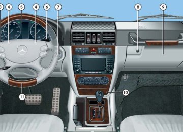
The hood lock release lever is located to the left of the steering wheel under the dashboard.
1 Hood lock release lever
! To avoid damage to the windshield wipers or hood, open the hood only with wipers in parked position. 왘 Pull release lever 1 upward.
The hood is unlocked.
G 500
2 Safety hook 왘 Lift hood up slightly. 왘 Pull safety hook 2 in direction ofarrow. The hood is unlocked.
왘 Open the hood.
G 55 AMG 3 Safety hook 왘 Lift hood up slightly. 왘 Push safety hook 3 in direction of
arrow. The hood is unlocked.
왘 Open the hood.
268
Closing
Warning!
When closing the hood, use extreme caution not to catch hands or fingers. Be careful that you do not close the hood on anyone.
Make sure that the hood is securely engaged before driving off. Do not continue driving if the hood can no longer engage after an accident, for example. The hood could otherwise come loose while the vehicle is in motion and endanger you and others.
왘 Lower hood and let it drop into lock from a height of approximately 0.7 ft (20 cm). The hood will lock audibly.
왘 Check to make sure the hood is fully
closed. If you can raise the hood at a point above the turn signals to the left and right of the hood, then it is not properly closed. Open it again and let it drop with somewhat greater force.
! Do not push the hood closed manually, as this could damage it.
Operation Engine compartment
Engine oil
The amount of oil your engine needs will depend on a number of factors, including driving style. Higher oil consumption can occur when 앫 the vehicle is new 앫 the vehicle is driven frequently at
higher engine speeds
Engine oil consumption checks should only be made after the vehicle break-in period.
! Do not use any special lubricant additives, as these may damage the drive assemblies. Using special additives not approved by Mercedes-Benz may cause damage not covered by the Mercedes-Benz Limited Warranty. More information on this subject is available at any Mercedes-Benz Light Truck Center.
269
Operation Engine compartment
Checking engine oil level with the control system When checking the oil level 앫 the vehicle must be parked on level
ground
앫 with the engine at operating tempera- ture, the vehicle must have been sta- tionary for at least 5 minutes with the engine turned off
앫 with the engine not at operating tem- perature yet, the vehicle must have been stationary for at least 30 minutes with the engine turned off
To check the engine oil level via the multifunction display, do the following: 왘 Switch on the ignition (컄 page 39). The standard display (컄 page 140) should appear in the multifunction display.
270
왘 Press button k or j on the
앫 Add
multifunction steering wheel until the following message appears in the multifunction display:
One of the following messages will subsequently appear in the multi- function display: 앫 Engine oil
level OK
1.0 qt to reach maximum oil level (Canada: 1.0 liter)
앫 Add
1.5 qts to reach maximum oil level (Canada: 1.5 liters)
앫 Add
2.0 qts to reach maximum oil level (Canada: 2.0 liters)
i If you want to interrupt the checking procedure, press button k or j on the multifunction steering wheel.
왘 If necessary, add engine oil
(컄 page 273).
For more information on engine oil, see the “Technical data” section (컄 page 423) and (컄 page 425).
Other display messages If the SmartKey is not turned to position 2 in the starter switch, the following message will appear:
Switch ignition on to check engine oil level 왘 Switch on the ignition (컄 page 39). If you see the message:
Observe waiting time 왘 If the engine is at operating
temperature, wait 5 minutes before repeating check procedure.
Operation Engine compartment
왘 If the engine is not at operating
왘 Have excess oil siphoned or drained
temperature yet, wait 30 minutes before repeating check procedure.
off. Contact an authorized Mercedes-Benz Light Truck Center.
If you see the message:
Engine oil level Not with engine on 왘 Turn off the engine. 왘 If the engine is at operating
temperature, wait 5 minutes before checking oil.
왘 If the engine is not at operating temperature yet, you must wait 30 minutes before checking oil.
If there is excess engine oil with the engine at operating temperature, the following message will appear:
! Excess oil must be siphoned or drained off. It could cause damage to the engine and/or catalytic converter not covered by the Mercedes-Benz Limited Warranty.
i G 500 only: Perform the engine oil level check with the oil dipstick if it cannot be completed with the control system (컄 page 272). In this case we recommend that you have the system checked at a Mercedes-Benz Light Truck Center.
For more information on messages in the multifunction display concerning engine oil, see the “Practical hints” section (컄 page 351).
Engine oil level Reduce oil level
271
Operation Engine compartment
Checking engine oil level with the oil dipstick (G 500 only) When checking the oil level 앫 the vehicle must be parked on level
ground
앫 with the engine at operating
temperature, the vehicle must have been stationary for at least 5 minutes with the engine turned off
앫 with the engine not at operating
temperature yet, the vehicle also must have been stationary for at least 5 minutes with the engine turned off
왘 Open the hood (컄 page 267).
272
왘 Pull out oil dipstick 1 again after approximately 3 seconds to obtain accurate reading. The oil level is correct when it is between lower mark 3 (min.) and upper mark 2 (max.) of the oil dipstick.
i The filling quantity between the upper and lower marks on the oil dipstick is approximately 2.1 US qt (2.0 l). 왘 If necessary, add engine oil
(컄 page 273).
For more information on engine oil, see the “Technical data” section (컄 page 423) and (컄 page 425). For more information on messages in the multifunction display concerning engine oil, see the “Practical hints” section (컄 page 351).
1 Oil dipstick 2 Upper mark 3 Lower mark 왘 Pull out oil dipstick 1. 왘 Wipe oil dipstick 1 clean. 왘 Fully insert oil dipstick 1 into the
dipstick guide tube.
Adding engine oil
! Only use approved engine oils and oil filters required for vehicles with Maintenance System (U.S. vehicles) or FSS (Canada vehicles). For a listing of approved engine oils and oil filters, refer to the Factory Approved Service Products pamphlet (USA only) in your vehicle literature portfolio, or contact an authorized Mercedes-Benz Light Truck Center. Using engine oils and oil filters of specification other than those expressly required for the Maintenance System (U.S. vehicles) or FSS (Canada vehicles), or changing of oil and oil filter at change intervals longer than those called for by the Maintenance System (U.S. vehicles) or FSS (Canada vehicles) will result in engine or emission control system damage not covered by the Mercedes-Benz Limited Warranty.
G 500
1 Filler capG 55 AMG 1 Filler cap
Operation Engine compartment
왘 Unscrew filler cap 1 from filler neck. 왘 Add engine oil as required. Never over-
fill with oil.
Be careful not to spill any oil when adding. Avoid environmental damage caused by oil entering the ground or water.
! Excess oil must be siphoned or drained off. It could cause damage to the engine and/or catalytic converter not covered by the Mercedes-Benz Limited Warranty. 왘 Screw filler cap 1 back on filler neck. For more information on engine oil, see the “Technical data” section (컄 page 423) and (컄 page 425).
Transmission fluid level
The transmission fluid level does not need to be checked. If you notice transmission fluid loss or gear shifting malfunctions, have an authorized Mercedes-Benz Light Truck Center check the automatic trans- mission.
273
Operation Engine compartment
Coolant level
The engine coolant is a mixture of water and anticorrosion/antifreeze. When checking the coolant level, 앫 the vehicle must be parked on level
ground
앫 the coolant temperature must be be-
low 158°F (70°C)
274
The coolant expansion tank is located on the passenger side of the engine compart- ment.
1 Cap
Warning!
In order to avoid any potentially serious burns: 앫 Use extreme caution when opening the hood if there are any signs of steam or coolant leaking from the cooling system, or if the coolant temperature display indicates that the coolant is overheated. 앫 Do not remove pressure cap on coolant
reservoir if coolant temperature is above 158°F (70°C). Allow engine to cool down before removing cap. The coolant reservoir contains hot fluid and is under pressure.
앫 Using a rag, slowly open the cap
approximately 1/2 turn to relieve excess pressure. If opened immediately, scald- ing hot fluid and steam will be blown out under pressure.
앫 Do not spill antifreeze on hot engine parts. Antifreeze contains ethylene glycol which may burn if it comes into contact with hot engine parts.
왘 Using a rag, turn cap 1 slowly approx- imately one half turn counterclockwise to release any excess pressure.
왘 Continue turning cap 1 counterclock-
wise and remove it. The coolant level is correct if the level 앫 for cold coolant: reaches the top of
the mark (plastic bridge) visible through the filling opening
앫 for warm coolant: is approximately
0.6 in (1.5 cm) higher 왘 Add coolant as required. 왘 Replace cap 1 on the filler neck. 왘 Tighten cap 1 clockwise until you
hear it click three times.
For more information on coolant, see “Coolants” (컄 page 427).
Windshield/rear window washer system and headlamp cleaning system
The windshield washer reservoir is located on the passenger side of the engine compartment.
1 Cap
Operation Engine compartment
Fluid for the windshield/rear window washer system and the headlamp cleaning system is supplied from the windshield washer reservoir. It has a capacity of 7.9 US qt (7.5 l). During all seasons, add MB Windshield Washer Concentrate “MB SummerFit” to water. Premix the windshield washer fluid in a suitable container.
Warning!
Washer solvent/antifreeze is highly flamma- ble. Do not spill washer solvent/antifreeze on hot engine parts, because it may ignite and burn. You could be seriously burned.
275
Operation Engine compartment
왘 Use the tab to pull cap 1 upwards. 왘 Refill the reservoir with MB Windshield Washer Concentrate “MB SummerFit” and water (or commercially available premixed windshield washer solvent/antifreeze, depending on ambient temperatures).
! Always use washer solvent/antifreeze where temperatures may fall below freezing point. Failure to do so could result in damage to the washer system/reservoir.
! Only use washer fluid which is suitable for plastic lenses. Improper washer fluid can damage the plastic lenses of the headlamps. 왘 Press cap 1 on the filler neck until it
has completely engaged.
For more information on filling up the washer reservoir, see “Windshield/rear window washer system and headlamp cleaning system” (컄 page 430).
276
왔 Tires and wheels Contact an authorized Mercedes-Benz Light Truck Center for information on test- ed and recommended rims and tires for summer and winter operation. They can also offer advice concerning tire service and purchase.
Warning!
Replace rims or tires with the same designa- tion, manufacturer and type as shown on the original part. See an authorized Mercedes-Benz Light Truck Center for fur- ther information. If incorrectly sized rims and tires are mounted: 앫 The wheel brakes or suspension
components can be damaged.
앫 The operating clearance of the wheels and the tires may no longer be correct.
Warning!
Worn, old tires can cause accidents. If the tire tread is badly worn, or if the tires have sustained damage, replace them.
When replacing rims, only use genuine Mercedes-Benz wheel bolts specified for the particular rim type. Failure to do so can result in the bolts loosening and possibly an accident.
Retreaded tires are not tested or recom- mended by Mercedes-Benz, since previous damage cannot always be recognized on retreads. The operating safety of the vehicle cannot be assured when such tires are used.
Operation Tires and wheels
Important guidelines
앫 Only use sets of tires and rims of the
same type and make.
앫 Tires must be of the correct size for the
rim.
앫 Break in new tires for approximately
60 miles (100 km) at moderate speeds.
앫 Regularly check the tires and rims for
damage. Dented or bent rims can cause tire inflation pressure loss and damage to the tire beads.
앫 If vehicle is heavily loaded, check tire
inflation pressure and correct as required.
앫 Do not allow your tires to wear down too far. Adhesion properties on wet roads are sharply reduced at tread depths of less than 1/8 in (3 mm).
앫 When replacing individual tires, you should mount new tires on the front wheels first (on vehicles with same-sized wheels all around).
277
Tire inspection Every time you check your tire inflation pressure, you should also inspect your tires for the following: 앫 excessive treadwear (컄 page 279) 앫 cord or fabric showing through the
tire’s rubber
Life of tire The service life of a tire is dependent upon varying factors including but not limited to: 앫 Driving style 앫 Tire inflation pressure 앫 Distance driven
앫 bumps, bulges, cuts, cracks or splits in
the tread or side of the tire
Warning!
Tires and spare tire should be replaced after 6 years, regardless of the remaining tread.
Replace the tire if you find any of the above conditions. Make sure you also inspect the spare tire periodically for condition and inflation. Spare tires will age and become worn over time even if never used, and thus should be inspected and replaced when necessary.
Operation Tires and wheels
Tire care and maintenance
Warning!
Regularly check the tires for damage. Dam- aged tires can cause tire inflation pressure loss. As a result, you could lose control of your vehicle.
Worn, old tires can cause accidents. If the tire tread is badly worn, or if the tires have sustained damage, replace them.
Regularly check your tire inflation pressure at least once a month. For more informa- tion on checking tire inflation pressure see “Recommended tire inflation pressure” (컄 page 286).
278
Tread depth Do not allow your tires to wear down too far. Adhesion properties on wet roads are sharply reduced at tread depths of less than 1/8 in (3 mm). Treadwear indicators (TWI) are required by law. These indicators are located in six places on the tread circumference and become visible at a tread depth of approx- imately 1/16 in (1.6 mm), at which point the tire is considered worn and should be replaced. Recommended minimum tire tread depth: 앫 Summer tires 1/8 in (3 mm) 앫 Winter tires 1/6 in (4 mm)
Warning!
Although the applicable federal motor safety laws consider a tire to be worn when the treadwear indicators (TWI) become visible at approximately 1/16 in (1.6 mm), we recom- mend that you do not allow your tires to wear down to that level. As tread depth approaches 1/8 in (3 mm), the adhesion properties on a wet road are sharply reduced.
Depending upon the weather and/or road surface (conditions), the tire traction varies widely.
Operation Tires and wheels
1 TWI (Tread Wear Indicator) The treadwear indicator appears as a solid band across the tread.
Storing tires
! Keep unmounted tires in a cool, dry place with as little exposure to light as possible. Protect tires from contact with oil, grease and gasoline.
Cleaning tires
! Never use a round nozzle to power wash tires. The intense jet of water can result in damage to the tire. Always replace a damaged tire.
279
Operation Tires and wheels
Direction of rotation
Loading the vehicle
Unidirectional tires offer added advan- tages, such as better hydroplaning per- formance. To benefit, however, you must make sure the tires rotate in the direction specified. An arrow on the sidewall indicates the intended direction of rotation (spinning) of the tire.
i Spare wheels may be mounted against the direction of rotation (spinning) even with a unidirectional tire for temporary use only until the regular drive wheel has been repaired or replaced. Always observe and follow applicable temporary use restrictions and speed limitations indicated on the spare wheel.
Two labels on your vehicle show how much weight it may properly carry. 1) The Tire and Loading Information
placard can be found on the driver’s door B-pillar. This placard tells you important information about the number of people that can be in the vehicle and the total weight that can be carried in the vehicle. It also contains information on the proper size and recommended tire inflation pressures for the original equipment tires on your vehicle.
2) The certification label, also found on
the driver’s door B-pillar tells you about the gross weight capacity of your vehi- cle, called the Gross Vehicle Weight Rating (GVWR). The GVWR includes the weight of the vehicle, all occupants, fuel and cargo. The certification label also tells you about the front and rear axle weight capacity, called the Gross Axle Weight Rating (GAWR). The GAWR
280
is the total allowable weight that can be carried by a single axle (front or rear). Never exceed the GVWR or GAWR for either the front axle or rear axle.
1 Driver’s door B-pillar Following is a discussion on how to work with the information contained on the Tire and Loading Information placard with regards to loading your vehicle.
Tire and Loading Information
Tire and Loading Information placard
i Data shown on Tire and Loading Information placard example are for illustration purposes only. Load limit data are specific to each vehicle and may vary from data shown in the illustration below. Refer to Tire and Loading Information placard on vehicle for actual data specific to your vehicle.
Warning!
Do not overload the tires by exceeding the specified load limit as indicated on the Tire and Loading Information placard on the driver’s door B-pillar. Overloading the tires can overheat them, possibly causing a blowout. Overloading the tires can also result in handling or steering problems, or brake failure.
Operation Tires and wheels
The Tire and Loading Information placard showing the load limit information is located on the driver’s door B-pillar (컄 page 280). 왘 Locate the statement “The combined weight of occupants and cargo should never exceed XXX kilograms or XXX lbs.” on the Tire and Loading Information placard. The combined weight of all occupants, cargo/luggage and trailer tongue load (if applicable) should never exceed the weight referenced in that statement.
1 Load limit information on the Tire and
Loading Information placard
281
Operation Tires and wheels
Seating capacity The seating capacity gives you important information on the number of occupants that can be in the vehicle. Observe front and rear seating capacity. The Tire and Loading Information placard showing the seating capacity is located on the driver’s door B-pillar (컄 page 280).
i Data shown on Tire and Loading Information placard example are for illustration purposes only. Seating data are specific to each vehicle and may vary from data shown in the illustration below. Refer to Tire and Loading Information placard on vehicle for actual data specific to your vehicle.
1 Seating capacity information on the Tire and Loading Information placard
Steps for determining correct load limit The following steps have been developed as required of all manufacturers under Title 49, Code of U.S. Federal Regulations, Part 575 pursuant to the “National Traffic and Motor Vehicle Safety Act of 1966”. Step 1
왘 Locate the statement “The combined weight of occupants and cargo should never exceed XXX kg or XXX lbs.” on your vehicle’s Tire and Loading Information placard.Step 2
왘 Determine the combined weight of thedriver and passengers that will be riding in your vehicle.
282
Step 3
왘 Subtract the combined weight of theStep 5
왘 Determine the combined weight ofdriver and passengers from XXX kilograms or XXX lbs.
Step 4
왘 The resulting figure equals the avail-able amount of cargo and luggage load capacity. For example, if the “XXX” amount equals 1400 lbs and there will be five 150 lbs passengers in your vehicle, the amount of available cargo and luggage load capacity is 650 lbs (1400 - 750 (5 x 150) = 650 lbs).
luggage and cargo being loaded on the vehicle. That weight may not safely exceed the available cargo and luggage load capacity calculated in step 4.
Step 6 (if applicable) 왘 If your vehicle will be towing a trailer,
load from your trailer will be trans- ferred to your vehicle. Consult this manual to determine how this reduces the available cargo and luggage load capacity of your vehicle (컄 page 285).
Operation Tires and wheels
The following table shows examples on how to calculate total and cargo load capacities with varying seating configura- tions and number and size of occupants. The following examples use a load limit of 1500 lbs. This is for illustration purposes only. Make sure you are using the actual load limit for your vehicle stated on the vehicle’s Tire and Loading Information placard (컄 page 281).
283
Operation Tires and wheels
Example Combined
weight limit of occupants and cargo from Tire and Loading Information placard 1500 lbs
1500 lbs
1500 lbs
Occupants weight
Number of occupants (driver and passengers)
Seating configu- ration
Combined weight of all occupants
Available cargo/luggage and trailer tongue weight (total load limit from Tire and Loading Information placard minus com- bined weight of all occupants)
front: 2
rear: 3
front: 1
rear: 2front: 1
Occupant 1: 150 lbs Occupant 2: 180 lbs Occupant 3: 160 lbs Occupant 4: 140 lbs Occupant 5: 120 lbs Occupant 1: 200 lbs Occupant 2: 190 lbs Occupant 3: 150 lbs Occupant 1: 150 lbs
750 lbs
1500 lbs - 750 lbs = 750 lbs
540 lbs
1500 lbs - 540 lbs = 960 lbs
150 lbs
1500 lbs - 150 lbs = 1350 lbs
The higher the weight of all occupants, the less cargo and luggage load capacity is available. For more information, see “Trailer tongue load” (컄 page 285).
284
Certification label Even after careful determination of the combined weight of all occupants, cargo and the trailer tongue load (if applicable) (컄 page 285) as to not exceed the permis- sible load limit, you must make sure that your vehicle never exceeds the Gross Vehicle Weight Rating (GVWR) and the Gross Axle Weight Rating (GAWR) for either the front or rear axle. You can obtain the GVWR and GAWR from the certification label. The certification label can be found on the driver’s door B-pillar, see “Technical data” (컄 page 412).
Gross Vehicle Weight Rating (GVWR): The total weight of the vehicle, all occupants, all cargo, and the trailer tongue load (if applicable) (컄 page 285) must never exceed the GVWR. Gross Axle Weight Rating (GAWR): The total allowable weight that can be carried by a single axle (front or rear). To assure that your vehicle does not exceed the maximum permissible weight limits (GVWR and GAWR for front and rear axle), have the loaded vehicle (including driver, passengers and all cargo and, if applicable, trailer fully loaded) weighed on a suitable commercial scale.
Operation Tires and wheels
Trailer tongue load The tongue load of any trailer is an impor- tant weight to measure because it affects the load you can carry in your vehicle. If a trailer is towed, the tongue load must be added to the weight of all occupants riding and any cargo you are carrying in the vehicle. The tongue load typically is 10 percent of the trailer weight and everything loaded in it. If an approved Mercedes-Benz trailer hitch is available for your G-Class vehicle model, consult the instructions included in the trailer hitch kit for vehicle towing capacity, permissible gross trailer weight, trailer tongue weight rating, and instructions on loading and towing a trailer.
285
Operation Tires and wheels
Recommended tire inflation pressure
Warning!
Follow recommended tire inflation pressures.
Do not underinflate tires. Underinflated tires wear excessively and/or unevenly, adversely affect handling and fuel economy, and are more likely to fail from being over- heated.
Do not overinflate tires. Overinflated tires can adversely affect handling and ride comfort, wear unevenly, increase stopping distance, and result in sudden deflation (blowout) because they are more likely to become punctured or damaged by road debris, potholes etc.
Do not overload the tires by exceeding the specified load limit as indicated on the Tire and Loading Information placard on the driver’s door B-pillar. Overloading the tires can overheat them, possibly causing a blowout. Overloading the tires can also result in handling or steering problems, or brake failure
Your vehicle is equipped with the Tire and Loading Information placard located on the driver’s door B-pillar (컄 page 280). The tire inflation pressure should be checked regularly and should only be adjusted on cold tires. The tires can be considered cold if the vehicle has been parked for at least 3 hours or driven less than 1 mile (1.6 km).
Follow recommended cold tire inflation pressures listed on the Tire and Loading Information placard on the driver’s door B-pillar. Keeping the tires properly inflated provides the best handling, tread life and riding comfort. In addition to the Tire and Loading Information placard on the driver’s door B-pillar, also consult the tire inflation pressure label (if available) on the inside of the fuel filler flap (컄 page 264) for any additional information pertaining to special driving situations. For more information, see “Important notes on tire inflation pressure” (컄 page 287).
286
i Data shown on Tire and Loading Information placard example are for illustration purposes only. Tire data are specific to each vehicle and may vary from data shown in the illustration below. Refer to Tire and Loading Information placard on vehicle for actual data specific to your vehicle.
1 Tire and Loading Information placard with recommended cold tire inflation pressures
The Tire and Loading Information placard lists the recommended cold tire inflation pressures for maximum loaded vehicle weight. The tire inflation pressures listed apply to the tires installed as original equipment.
Important notes on tire inflation pressure
Warning!
If the tire inflation pressure drops repeatedly: 앫 Check the tires for punctures from
foreign objects.
앫 Check to see whether air is leaking from
the valves or from around the rim.
Tire temperature and tire inflation pressure are also increased while driving, depending on the driving speed and the tire load. If you will be driving your vehicle at high speeds of 100 mph (160 km/h) or higher, where it is legal and conditions allow, consult the tire inflation pressure label on the inside of the fuel filler flap (if available) on how to adjust the cold tire inflation pressure. If you do not adjust the tire infla- tion pressure, excessive heat can build up and result in sudden tire failure.
Operation Tires and wheels
If your vehicle is not equipped with the tire inflation pressure label on the inside of the fuel filler flap, contact an authorized Mercedes-Benz Light Truck Center for proper tire inflation pressure.
i Driving comfort may be reduced when the tire inflation pressure is adjusted to the value for speeds above 100 mph (160 km/h) as specified on the tire inflation pressure label (if available) located on the inside of the fuel filler flap.
Be sure to readjust the tire inflation pressure for normal driving speeds. You should wait until the tires are cold before adjusting the tire inflation pressure. Some vehicles may have supplemental tire inflation pressure information for vehicle loads less than the maximum loaded vehicle condition. If such information is provided, it can be found on the tire inflation pressure label located on the inside of the fuel filler flap (컄 page 264).
287
Do not overload the tires by exceeding the specified load limit as indicated on the Tire and Loading Information placard on the driver’s door B-pillar. Overloading the tires can overheat them, possibly causing a blowout. Overloading the tires can also result in handling or steering problems, or brake failure.
Warning!
Follow recommended tire inflation pressures.
Do not underinflate tires. Underinflated tires wear excessively and/or unevenly, adversely affect handling and fuel economy, and are more likely to fail from being over- heated.
Do not overinflate tires. Overinflated tires can adversely affect handling and ride comfort, wear unevenly, increase stopping distance, and result in sudden deflation (blowout) because they are more likely to become punctured or damaged by road debris, potholes etc.
Operation Tires and wheels
Tire inflation pressure changes by approxi- mately 1.5 psi (0.1 bar) per 18°F (10°C) of air temperature change. Keep this in mind when checking tire inflation pressure where the temperature is different from the outside temperature.
Checking tire inflation pressure
Regularly check your tire inflation pressure at least once a month. Check and adjust the tire inflation pressure when the tires are cold. The tires can be considered cold if the vehicle has been parked for at least 3 hours or driven less than 1 mile (1.6 km). If you check the tire inflation pressure when the tires are warm (the vehicle has been driven for several miles or sitting less than 3 hours), the reading will be approximately 4 psi (0.3 bar) higher than the cold reading. This is normal. Do not let air out to match the specified cold tire inflation pressure. Otherwise, the tire will be underinflated.
288
Checking tire pressure electronically with the Advanced Tire Pressure Monitoring System (Advanced TPMS)
i USA only: The Tire Pressure Monitoring System (TPMS) is equipped with a combination low tire pres- sure/TPMS malfunction telltale in the instru- ment cluster (컄 page 26). Depending on how the telltale illuminates, it indicates a low tire pres- sure condition or a malfunction in the TPMS sys- tem itself: 앫 If the telltale illuminates continuously, one or more of your tires is significantly under-in- flated. There is no malfunction in the TPMS.
앫 If the telltale flashes for 60 seconds and
then stays illuminated, the TPMS system it- self is not operating properly.
Checking tire inflation pressure manually Follow the steps below to achieve correct tire inflation pressure: 왘 Remove the cap from the valve on one
tire.
왘 Firmly press a tire gauge onto the
valve.
왘 Read tire inflation pressure on tire gauge and check against the recom- mended tire inflation pressure on the Tire and Loading Information placard on the driver’s door B-pillar (컄 page 280). If necessary, add air to achieve the recommended tire inflation pressure.
i If you have overfilled the tire, release tire inflation pressure by pushing the metal stem of the valve with e.g. a tip of a pen. Then recheck the tire inflation pressure with the tire gauge. 왘 Install the valve cap. 왘 Repeat this procedure for each tire.
Operation Tires and wheels
i USA only: This device complies with Part 15 of the FCC Rules. Operation is subject to the following two conditions: (1) This device may not cause harmful interfer-
ence, and
(2) this device must accept any interference received, including interference that may cause undesired operation.
Any unauthorized modification to this device could void the user’s authority to operate the equipment.
i Canada only: This device complies with RSS-210 of Industry Canada. Operation is subject to the following two conditions: (1) This device may not cause interference, and (2) this device must accept any interference received, including interference that may cause undesired operation of the device. Any unauthorized modification to this device could void the user’s authority to operate the equipment.
289
Operation Tires and wheels
The TPMS only functions on wheels that are equipped with the proper electronic sensors. It monitors the tire inflation pres- sure, as selected by the driver, in all four tires. A warning is issued to alert you to a decrease in pressure in one or more of the tires. Tire pressure inquiries are made using the multifunction display.The present inflation pressures are displayed only after a few minutes travel time.
i Possible differences between the readings of a tire pressure gauge of an air hose, e.g. gas station equipment, and the vehicle’s control system can occur. Usually the readings issued by the control system are more precise.
290
왘 Switch on the ignition (컄 page 39). 왘 Press button j or k until the
current inflation pressures for each tire appear in the multifunction display.
Example illustration i When the vehicle has been parked for longer than 20 minutes, the message Tire pressure displayed only after driving for a few minutes appears in the multifunction display.
Warning!
It is the driver’s responsibility to calibrate the TPMS on the recommended cold infla- tion pressure. Underinflated tires affect the ability to steer or brake the vehicle. You might lose control over the vehicle.
i With a spare wheel mounted, the system may still indicate the tire inflation pressure of the removed road wheel for some minutes. If this happens, keep in mind that the indicated value where the spare wheel is mounted does not reflect the actual spare tire inflation pressure.
Warning!
Warning!
The Advanced TPMS does not indicate a warning for wrongly selected inflation pres- sures. Always adjust tire inflation pressure according to the Tire and Loading Informa- tion placard on the driver’s door B-pillar or, if available, the supplemental tire inflation pressure information on the inside of the fuel filler flap.
The Advanced TPMS is not able to issue a warning due to a sudden dramatic loss of pressure (e.g. tire blowout caused by a for- eign object). In this case bring the vehicle to a halt by carefully applying the brakes and avoiding abrupt steering maneuvers.
Each tire, including the spare (if provided), should be checked monthly when cold and inflated to the inflation pressure recom- mended by the vehicle manufacturer on the Tire and Loading Information placard or the tire inflation pressure label (if available). If your vehicle has tires of a different size than the size indicated on the Tire and Loading Information placard or the tire inflation pressure label (if available), you should determine the proper tire inflation pressure for those tires. As an added safety feature, your vehicle has been equipped with an Advanced Tire Pres- sure Monitoring System (Advanced TPMS) that illuminates a low tire pressure telltale when one or more of your tires is significant- ly underinflated. Accordingly, when the low tire pressure telltale illuminates, you should stop and check your tires as soon as possi- ble, and inflate them to the proper pressure.
Operation Tires and wheels
Driving on a significantly underinflated tire causes the tire to overheat and can lead to tire failure.
Underinflation also reduces fuel efficiency and tire tread life, and may affect the vehi- cle’s handling and stopping ability. Please note that the Advanced TPMS is not a sub- stitute for proper tire maintenance, and it is the driver’s responsibility to maintain cor- rect tire pressure, even if underinflation has not reached the level to trigger illumination of the Advanced TPMS low tire pressure tell- tale.
USA only: Your vehicle has also been equipped with a Advanced TPMS malfunc- tion indicator to indicate when the system is not operating properly. The Advanced TPMS malfunction indicator is combined with the low tire pressure telltale. When the system detects a malfunction, the telltale will flash for approximately 1 minute and then remain continuously illuminated. This sequence will continue upon subsequent vehicle start-ups as long as the malfunction exists.
컄컄
291
Operation Tires and wheels
컄컄
USA only: When the malfunction indicator is illuminated, the system may not be able to detect or signal low tire pressure as intended.
USA only: Advanced TPMS malfunctions may occur for a variety of reasons, including the installation of replacement or alternate tires or wheels on the vehicle that prevent the Advanced TPMS from functioning prop- erly. Always check the Advanced TPMS mal- function telltale after replacing one or more tires or wheels on your vehicle to ensure that the replacement or alternate tires and wheels allow the Advanced TPMS to contin- ue to function properly.
i Operating radio transmission equipment (e.g. wireless headsets, two-way radios) in or near the vehicle could cause the Advanced TPMS to malfunction.
292
Tire inflation pressure warnings If the system detects a significant loss of tire inflation pressure in one or more than one tire, a message appears in the multi- function display.
Example illustration The respective tire is indicated by a red rectangle. In addition, a warning signal sounds.
Restarting Advanced TPMS The TPMS usually recognizes new refer- ence values automatically, for example when you have 앫 adjusted the tire inflation pressure 앫 changed wheels or tires 앫 mounted new wheels or tires
Warning!
It is the driver’s responsibility to calibrate the TPMS on the recommended cold infla- tion pressure. Underinflated tires affect the ability to steer or brake the vehicle. You might lose control over the vehicle.
왘 Press button è or ÿ on the mul-
tifunction steering wheel repeatedly until the standard display menu appears in the multifunction display.
왘 Press button j or k repeatedly
until you see the current inflation pressures for each tire appear in the multifunction display or the following message appears in the multifunction display: Tire pressure displayed only after driving for a few minutes
If you want to set new reference values manually: 왘 Using the Tire and Loading Information
placard on the driver’s door B-pillar (컄 page 280) or, if available, the supplemental tire inflation pressure information on the inside of the fuel filler flap (컄 page 264), make sure the tire inflation pressure of all four tires is correct.
i Restart the TPMS after adjusting the tire in- flation pressure to the inflation pressure recom- mended for the vehicle operating condition. Tire pressure should only be adjusted on cold tires. Observe the recommended tire inflation pres- sure on the Tire and Loading Information placard on the driver’s door B-pillar (컄 page 280). Some vehicles may have supplemental tire inflation pressure information for driving at high speeds (컄 page 287) or for vehicle loads less than the maximum loaded vehicle condition (컄 page 287). If such information is provided, it can be found on the inside of the fuel filler flap (컄 page 264).
Operation Tires and wheels
왘 Press the reset button (컄 page 130). The following message will appear in the multifunction display: Restart tire pressure monitor?
왘 Press the æ button.
The following message will appear in the multifunction display: Tire pressure monitor restarted After driving a few minutes the system verifies that the current tire inflation pressures are within the system’s specified range. Afterwards the current tire inflation pressures are accepted as reference pressures and then moni- tored.
If you wish to cancel activation: 왘 Press the ç button.
293
Tire labeling
Besides tire name (sales designation) and manufacturer name, a number of markings can be found on a tire. Following are some explanations for the markings on your vehicle’s tires:
Operation Tires and wheels
Potential problems associated with underinflated and overinflated tires
Underinflated tires Underinflated tires can: 앫 cause excessive and uneven tire wear 앫 adversely affect fuel economy 앫 lead to tire failure from being
overheated
앫 adversely affect handling
characteristics
Warning!
Follow recommended tire inflation pressures.
Do not underinflate tires. Underinflated tires wear excessively and/or unevenly, adversely affect handling and fuel economy, and are more likely to fail from being overheated.
Overinflated tires Overinflated tires can: 앫 adversely affect handling
characteristics
앫 cause uneven tire wear 앫 be more prone to damage from road
hazards
앫 adversely affect ride comfort 앫 increase stopping distance
Warning!
Follow recommended tire inflation pressures.
Do not overinflate tires. Overinflated tires can adversely affect handling and ride comfort, wear unevenly, increase stopping distance, and result in sudden deflation (blowout) because they are more likely to become punctured or damaged by road debris, potholes etc.
294
1 Uniform Quality Grading Standards
(컄 page 302)
Tire size designation, load and speed rating
2 DOT, Tire Identification Number (TIN)
(컄 page 299)
3 Maximum tire load (컄 page 300) 4 Maximum tire inflation pressure
(컄 page 301) 5 Manufacturer 6 Tire ply material (컄 page 304) 7 Tire size designation, load and speed
rating (컄 page 295)
8 Load identification (컄 page 298) 9 Tire name
i For illustration purposes only. Actual data on tires are specific to each vehicle and may vary from data shown in above illustration. For more information, see “Rims and tires” (컄 page 416).
1 Tire width 2 Aspect ratio in % 3 Radial tire code 4 Rim diameter 5 Tire load rating 6 Tire speed rating
i For illustration purposes only. Actual data on tires are specific to each vehicle and may vary from data shown in above illustration.
Operation Tires and wheels
General: Depending on the design standards used, the tire size molded into the sidewall may have no letter or a letter preceding the tire size designation. No letter preceding the size designation (as illustrated above): Passenger car tire based on European design standards. Letter “P” preceding the size designation: Passenger car tire based on U.S. design standards. Letter “LT” preceding the size designation: Light Truck tire based on U.S. design standards. Letter “T” preceding the size designation: Temporary spare tires which are high pressure compact spares designed for temporary emergency use only.
295
Operation Tires and wheels
Tire width The tire width 1 (컄 page 295) indicates the nominal tire width in mm.
Aspect ratio The aspect ratio 2 (컄 page 295) is the dimensional relationship between tire section height and section width and is expressed in percentage. The aspect ratio is arrived at by dividing section height by section width.
Tire code The tire code 3 (컄 page 295) indicates the tire construction type. The “R” stands for radial tire type. Letter “D” means diagonal or bias ply construction; letter “B” means belted-bias ply construction. At the tire manufacturer’s option, any tire with a speed capability above 149 mph (240 km/h) can include a “ZR” in the size designation (for example: 245/40 ZR 18). For additional information, see “Tire speed rating” (컄 page 297).
296
Rim diameter The rim diameter 4 (컄 page 295) is the diameter of the bead seat, not the diameter of the rim edge. Rim diameter is indicated in inches (in).
Tire load rating The tire load rating 5 (컄 page 295) is a numerical code associated with the maximum load a tire can support.