- 2012 Mercedes-Benz G Class Owners Manuals
- Mercedes-Benz G Class Owners Manuals
- 2005 Mercedes-Benz G Class Owners Manuals
- Mercedes-Benz G Class Owners Manuals
- 2013 Mercedes-Benz G Class Owners Manuals
- Mercedes-Benz G Class Owners Manuals
- 2009 Mercedes-Benz G Class Owners Manuals
- Mercedes-Benz G Class Owners Manuals
- 2003 Mercedes-Benz G Class Owners Manuals
- Mercedes-Benz G Class Owners Manuals
- 2004 Mercedes-Benz G Class Owners Manuals
- Mercedes-Benz G Class Owners Manuals
- 2011 Mercedes-Benz G Class Owners Manuals
- Mercedes-Benz G Class Owners Manuals
- 2002 Mercedes-Benz G Class Owners Manuals
- Mercedes-Benz G Class Owners Manuals
- 2007 Mercedes-Benz G Class Owners Manuals
- Mercedes-Benz G Class Owners Manuals
- Download PDF Manual
-
Always remember to disengage the differen- tial locks when returning to drive on paved roads, see “A few words about differentials and differential locks” (컄 page 174).
Controls in detail Differential locks
Rear axle differential lock 왘 Press switch 2.
The yellow engagement indicator lamp 4 comes on first, followed by the red function indicator lamp 5. The rear axle differential lock is switched on.
Front differential lock 왘 Press switch 3.
The yellow engagement indicator lamp 4 comes on first, followed by the red function indicator lamp 5. The front differential lock is switched on.
176
왔 Good visibility For information on windshield wipers, see “Windshield wipers” (컄 page 58).
Headlamp cleaning system
The button is located on the dashboard to the left of the steering wheel.
1 Headlamp cleaning button 왘 Switch on the ignition (컄 page 39). 왘 Press button 1.
The headlamps are cleaned with a high-pressure water jet.
i The headlamps will automatically be cleaned when you have 앫 switched on the headlamps
and
앫 operated the windshield wipers with windshield washer fluid fifteen times
When you switch off the ignition, the counter resets.
For information on filling up the washer reservoir, see “Windshield/rear window washer system and headlamp cleaning system” (컄 page 275).
Rear view mirrors
For more information on setting the rear view mirrors, see “Mirrors” (컄 page 46).
Auto-dimming rear view mirrors The reflection brightness of the exterior rear view mirrors and the interior rear view mirror will respond automatically to glare when
Controls in detail Good visibility
앫 the ignition is switched on
and
앫 incoming light from headlamps falls on
the sensor in the interior rear view mirror
The exterior rear view mirrors and the interior rear view mirror will not react if 앫 reverse gear R is engaged 앫 the interior lighting is turned on
Warning!
The auto-dimming function does not react if incoming light is not aimed directly at sensors in the interior rear view mirror.
The interior rear view mirror and the exterior rear view mirrors do not react, for example, when transporting cargo which covers the rear window.
Light hitting the mirror(s) at certain angles (incident light) could blind you. As a result, you may not be able to observe traffic conditions and could cause an accident.
177
Controls in detail Good visibility
Warning!
The exterior rear view mirror buttons are located above the exterior lamp switch.
Exercise care when using the passen- ger-side exterior rear view mirror. The mirror surface is convex (outwardly curved surface for a wider field of view). Objects in mirror are closer than they appear. Check your interior rear view mirror or glance over your shoulder before changing lanes.
Activating exterior rear view mirror parking position Follow these steps to activate the mirror parking position so that the passen- ger-side exterior rear view mirror will be turned downward to the stored position.
178
1 Driver’s side exterior rear view mirror
button
2 Passenger-side exterior rear view
mirror button
왘 Switch on the ignition (컄 page 39). 왘 Make sure you have stored a parking position for the passenger-side exterior rear view mirror (컄 page 116).
왘 Press button 2.
The passenger-side exterior rear view mirror is selected.
왘 Move the gear selector lever to reverse
gear R. The passenger-side exterior rear view mirror will be turned downward to the stored position.
The exterior rear view mirror returns to its previously stored driving position: 앫 10 seconds after moving the gear
selector lever out of position R
앫 immediately once you exceed a vehicle
speed of approximately 6 mph (10 km/h)
앫 immediately when you press button 1
for driver’s side exterior rear view mirror
Sun visors
The sun visors protect you from sun glare while driving.
Warning!
Do not use the vanity mirror while driving. Keep the mirrors in the sun visors closed while vehicle is in motion. Reflected glare can endanger you and others.
1 Sun visor 2 Mounting
3 Vanity mirror cover 4 Vanity mirror lamps
Glare through the windshield 왘 Swing sun visor 1 down. 왘 When you do not experience glare
anymore, swing sun visor 1 up.
Controls in detail Good visibility
Vanity mirror
i Make sure the ignition is switched on (컄 page 39) and sun visor 1 is properly engaged in mounting 2. 왘 Swing sun visor 1 down. 왘 Flip up vanity mirror cover 3 to access
vanity mirror. Vanity mirror lamps 4 come on.
왘 After using vanity mirror, flip down
vanity mirror cover 3. 왘 Swing sun visor 1 up.
179
Controls in detail Good visibility
Glare to a side window 왘 Swing sun visor 1 down. 왘 Disengage sun visor 1 from
mounting 2.
! To avoid damage to vanity mirror cover 3, make sure it is closed before pivoting sun visor 1 to the side. 왘 Pivot sun visor 1 to the side. 왘 When you do not experience glare anymore, pivot sun visor 1 to the windshield.
왘 Engage sun visor 1 into mounting 2. 왘 Swing sun visor 1 up.
180
The windshield defroster switch is located on the upper part of the center console.
1 Windshield defroster switch 2 Indicator lamp Switch on the ignition (컄 page 39).
Windshield defroster
The windshield defroster uses a large amount of power. To keep battery drain to a minimum, switch off the windshield defroster as soon as the windshield is clear. The windshield defroster switches off automatically after 10 minutes. If you switch on the windshield defroster for the fourth time in succession, it will switch off automatically after 5 minutes. You cannot switch on the windshield defroster if the outside temperature is above 10°C (50°F).
Warning!
Any accumulation of snow and ice should be removed from the windshield before driving. Visibility could otherwise be impaired, endangering you and others.
Activating 왘 Press switch 1.
Indicator lamp 2 comes on.
Deactivating 왘 Press switch 1 once more. Indicator lamp 2 goes out.
! If too many electrical consumers are operating simultaneously and there is insuffi- cient voltage in the battery, indicator lamp 2 in windshield defroster switch 1 starts flashing. After approximately 30 seconds the system responds automatically by switching the windshield defroster off.
Controls in detail Good visibility
Rear window defroster
The rear window defroster uses a large amount of power. To keep battery drain to a minimum, switch off the rear window defroster as soon as the rear window is clear. The rear window defroster switches off automatically after approximately 6 to 17 minutes of operation depending on the outside temperature.
Warning!
Any accumulation of snow and ice should be removed from the rear window before driv- ing. Visibility could otherwise be impaired, endangering you and others.
Switch on the ignition (컄 page 39).
Activating 왘 Press button 1 or F on the
respective climate control panel (컄 page 183). The indicator lamp on the button comes on.
Deactivating 왘 Press button 1 or F once more. The indicator lamp on the button goes out.
! If the rear window defroster switches off too soon and the indicator lamp in button 1 or F starts flashing, too many electrical consumers are operating simultaneously and there is insufficient voltage in the battery. The system responds automatically by switching the rear window defroster off. As soon as the battery has sufficient voltage, the rear window defroster switches back on auto- matically.
181
Controls in detail Climate control
182
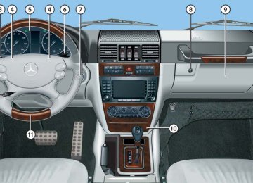
Item
1 Left side defroster air vent, fixed 2 Left side air vent, adjustable 3 Thumbwheel for air volume control
for left side air vent
4 Left front defroster air vent 5 Thumbwheel for air volume control
for left center air vent
6 Left center air vent, adjustable 7 Right center air vent, adjustable 8 Thumbwheel for air volume control
for right center air vent
9 Right front defroster air vent a Thumbwheel for air volume control
for right side air vent
b Right side air vent, adjustable c Right side defroster air vent, fixed d Right footwell air vent e Climate control panel f Left footwell air vent
i For draft-free ventilation, move the sliders for the center air vents and side air vents to the middle position.
Climate control panel (U.S. vehicles)
Controls in detail Climate control
Item
1 Air volume control 2 Left side temperature control 3 Right side temperature control 4 Air distribution control 5 Rear window defroster (컄 page 181) 6 AC cooling on/off
Residual heat/ventilation
7 Air distribution and air volume
(automatic mode)
8 Air recirculation 9 Front defroster
Climate control panel (Canada vehicles)
183
i Severe conditions (e.g. strong air pollution) may require replacement of the filter before its scheduled interval. A clogged filter will reduce the air volume to the interior. If the vehicle interior is hot, ventilate the interior before driving off, see “Summer opening fea- ture” (컄 page 193). The climate control will then adjust the interior temperature to the set value much faster. Keep the air intake grille in front of the wind- shield free of snow and debris.
Controls in detail Climate control
The climate control is operational when- ever the engine is running. You can oper- ate the climate control system in either the automatic or manual mode. The system cools or heats the interior depending on the selected interior temperature and the current outside temperature.
Nearly all dust particles, pollutants and odors are filtered out before outside air enters the passenger compartment through the air distribution system. The air conditioning will not engage (no cooling) if the A/C mode is deactivated (컄 page 189).
Warning!
Warning!
Follow the recommended settings for heating and cooling given on the following pages. Otherwise the windows could fog up, impairing visibility and endangering you and others.
When operating the climate control, the air that enters the passenger compartment through the air vents can be very hot or very cold (depending on the set temperature). This may cause burns or frostbite on unpro- tected skin in the immediate area of the air vents. Always keep sufficient distance between unprotected parts of the body and the air vents. If necessary, use the air distri- bution control (컄 page 186) to direct the air to air vents in the vehicle interior that are not in the immediate area of unprotected skin.
184
Deactivating the climate control system
Operating the climate control system in automatic mode
Warning!
When the climate control is switched off, the outside air supply and circulation are also switched off. Only choose this setting for a short time. Otherwise the windows could fog up, impairing visibility and endangering you and others.
Deactivating 왘 Set air volume control 1 (컄 page 183)
to position 0.
Reactivating 왘 Make sure the ignition is switched on
(컄 page 39).
왘 Set air volume control 1 (컄 page 183)
to any speed. The previous settings are once again in effect.
i When operating the climate control system in automatic mode, you will only rarely need to adjust the temperature, air volume and air distribution. In automatic mode, cooling with dehumidify is switched on. This function can be switched off by pressing button 9 if necessary (컄 page 189).
Activating 왘 Press button U (컄 page 183) while
the engine is running. The indicator lamp on the button comes on. The air volume and air distribution are adjusted automatically. 왘 Use temperature controls 2 and 3 (컄 page 183) to separately adjust the air temperature on each side of the passenger compartment. The interior air temperature is adjusted automatically.
Controls in detail Climate control
Deactivating 왘 Press button U (컄 page 183) once
more. The indicator lamp on the button goes out. The automatic operation of the air volume and air distribution switches off.
Setting the temperature
Use temperature controls 2 and 3 (컄 page 183) to separately adjust the air temperature on each side of the passenger compartment. You should raise or lower the temperature setting in small incre- ments, preferably starting at 72°F (22°C). The climate control will adjust to the set temperature as fast as possible.
185
Controls in detail Climate control
Increasing 왘 Turn temperature control 2
and/or 3 (컄 page 183) slightly clockwise. The climate control system will correspondingly adjust the interior air temperature.
i If you turn the temperature control fully clockwise for one side of the vehicle, you are increasing the temperature for the other side of the vehicle as well.
Decreasing 왘 Turn temperature control 2
and/or 3 (컄 page 183) slightly counterclockwise. The climate control system will correspondingly adjust the interior air temperature.
i If you turn the temperature control fully counterclockwise for one side of the vehicle, you are decreasing the temperature for the other side of the vehicle as well.
186
Adjusting air distribution
왘 Press button U (컄 page 183).
Use air distribution control 4 (컄 page 183) to adjust the air distribution. The following symbols are found on the controls:
Symbol Function a Directs air through the center,
side, and rear passenger compartment air vents
Z Directs air to the windshield
and the side defroster air vents
b Directs air into the entire
vehicle interior
Y Directs air to the footwells
The indicator lamp on the button goes out. The automatic air distribution con- trol is switched off. The air distribution is adjusted according to the currently selected setting.
왘 Turn air distribution control 4
(컄 page 183) to the desired symbol.
Adjusting air volume
Six blower speeds are available. 왘 Press button U (컄 page 183).
The indicator lamp on the button goes out. The automatic air volume control is switched off. The air volume is adjusted according to the currently selected setting.
왘 Turn air volume control 1
(컄 page 183) to the desired blower speed.
Closing the side air vents 왘 Turn thumbwheel 3 and/or a
(컄 page 182) to the left. Side air vent 2 and/or b (컄 page 182) is closed.
Front defroster
You can use this setting to defrost the windshield, for example if it is iced up. You can also defog the windshield and the side windows.
i Keep this setting selected only until the windshield or the side windows are clear again.
Adjusting air volume for the center air vents
Opening the center air vents 왘 Turn thumbwheel 5 and/or 8
(컄 page 182) to the right. Center air vent 6 and/or 7 (컄 page 182) is open.
Closing the center air vents 왘 Turn thumbwheel 5 and/or 8
(컄 page 182) to the left. Center air vent 6 and/or 7 (컄 page 182) is closed.
Adjusting air volume for the side air vents
Opening the side air vents 왘 Turn thumbwheel 3 and/or a
(컄 page 182) to the right. Side air vent 2 and/or b (컄 page 182) is open.
Controls in detail Climate control
Activating 왘 Press button 0 or P
(컄 page 183). The indicator lamp on the button comes on. The climate control switches to the following functions automatically: 앫 maximum blower speed and
heating power
앫 air flows onto the windshield and
the front side windows (side air vents must be open)
앫 the air recirculation mode is
switched off
i If you have switched on the defrost function using button 0 or P, you cannot make any other settings.
187
Controls in detail Climate control
Deactivating 왘 Press button 0 or P
(컄 page 183) once more. The indicator lamp on the button goes out. Defrosting is switched off.
i The cooling remains switched on.
Air recirculation mode
Switch to air recirculation mode to prevent unpleasant odors from entering the vehicle from the outside (e.g. before driving through a tunnel). This setting cuts off the intake of outside air and recirculates the air in the passenger compartment.
Windshield fogged on the outside
i Keep this setting selected only until the windshield is clear again. 왘 Switch the windshield wipers on
(컄 page 58).
If the automatic mode of the climate control is switched off: 왘 Turn air distribution control 4 to a or Y (컄 page 183).
Warning!
Fogged windows impair visibility, endanger- ing you and others. If the windows begin to fog on the inside, switching off the air recirculation mode immediately should clear interior window fogging. If interior window fogging persists, make sure the air conditioning (컄 page 189) is activated, or press button 0 or P.
Activating 왘 Press button , (컄 page 183). The indicator lamp on the button comes on.
i The air recirculation mode is activated automatically at high outside temperatures. The indicator lamp on button , is not lit when the air recirculation mode is switched on auto- matically. A quantity of outside air is added after approxi- mately 30 minutes. If you have turned off the air conditioning (컄 page 189) or the outside temperature is below 41°F (5°C), the air recirculation mode will not switch on automatically.
188
Deactivating 왘 Press button , (컄 page 183) once
more. The indicator lamp on the button goes out.
i The air recirculation mode is deactivated automatically: 앫 after 5 minutes if the outside temperature is
below approximately 41°F (5°C)
앫 after 5 minutes if the air conditioning is
turned off
Air conditioning
The cooling function, only operational when the engine is running, cools the vehicle interior down to the selected temperature. The cooling function also dehumidifies the air in the vehicle interior, thus preventing the windows from fogging up.
i Condensation may drip out from underneath the vehicle. This is normal and not an indication of a malfunction.
앫 after 30 minutes if the outside temperature
is above approximately 41°F (5°C)
Warning!
If you turn off the cooling function, the inte- rior air is not dried. The windows can fog up more quickly. Window fogging may impair visibility and endanger you and others.
Controls in detail Climate control
Deactivating It is possible to deactivate the air condi- tioning (cooling) function of the climate control system. The air in the vehicle will then no longer be cooled or dehumidified. 왘 Press button 9 (컄 page 183).
The indicator lamp on the button goes out. The cooling function switches off after a short delay.
189
Controls in detail Climate control
Activating Moist air can fog up the windows. You can dehumidify the air with the air condition- ing. 왘 Press button 9 (컄 page 183) once
more. The indicator lamp on the button comes on.
The air conditioning uses the refrigerant R134a. This refrigerant is free of CFCs which are harmful to the ozone layer.
! If the air conditioning cannot be turned on again, this indicates that the air conditioning is losing refrigerant. The compressor has turned itself off. Have the air conditioning checked at the nearest authorized Mercedes-Benz Light Truck Center.
Residual heat and ventilation
With the engine switched off, it is possible to continue to heat or ventilate the interior for up to 30 minutes. This feature makes use of the residual heat produced by the engine.
i How long the system will provide heating depends on 앫 the coolant temperature 앫 the battery voltage Regardless of the temperature and air volume set on the climate control panel, an interior temperature is aimed at by 72°F (22°C) and the blower runs on low speed to protect the vehicle battery.
Activating 왘 Turn the SmartKey in the starter switch
to position 0 or 1 (컄 page 39).
or 왘 Remove the SmartKey from the starter
switch.
왘 Press button 9 (컄 page 183). The indicator lamp on the button comes on.
Deactivating 왘 Press button 9 (컄 page 183) once
more. The indicator lamp on the button goes out.
i The residual heat is automatically turned off: 앫 when the ignition is switched on 앫 after about 30 minutes 앫 if the coolant temperature is too low 앫 if the battery voltage drops
190
Rear passenger compartment adjustable air vents
The air conditioning for the rear passenger compartment is controlled via the climate control panel (컄 page 183). The air vents for the rear passenger compartment are located in the rear center console.
Controls in detail Climate control
Adjusting air distribution 왘 Push the slide for the left center
vent 2 or right center air vent 3 to the left, right, up, or down. The air flow is directed in the corresponding direction.
i For draft-free ventilation, move the sliders for the center air vents 2 and 3 upward.
1 Thumbwheel for air volume control for
center air vents
2 Left center air vent, adjustable 3 Right center air vent, adjustable
i The temperature at the center air vents 2 and 3 for the rear passenger compartment is the same as at the dashboard center air vents.
Adjusting air volume 왘 Turn thumbwheel 1 up.
The air volume is increased. 왘 Turn thumbwheel 1 down. The air volume is decreased.
191
Controls in detail Power windows
Opening and closing
The side windows are opened and closed electrically. The switches for all side windows are located on the driver’s door control panel. The switches for the respec- tive side windows are located on the front passenger door and the rear doors.
1 Override switch (컄 page 86) 2 Left front window 3 Right front window 4 Right rear window 5 Left rear window
192
Warning!
When closing the windows, make sure there is no danger of anyone being harmed by the closing procedure. Activate the override switch (컄 page 86) when children are riding in the back seats of the vehicle. The children could otherwise injure themselves, e.g. by becoming trapped in the window opening.
The closing procedure can be immediately halted by releasing the switch or by releas- ing button ‹ on the SmartKey. When leaving the vehicle, always remove the SmartKey from starter switch, take it with you, and lock the vehicle. Do not leave chil- dren unattended in the vehicle, or with ac- cess to an unlocked vehicle. Unsupervised use of vehicle equipment can cause an accident and/or serious personal injury.
i You can also open or close the windows using the SmartKey, see “Summer opening fea- ture” (컄 page 193) and see “Convenience clos- ing feature” (컄 page 194). 왘 Switch on the ignition (컄 page 39).
Opening the windows 왘 Press switch 2, 3, 4 or 5 to the
resistance point. The corresponding window will move downwards until you release the switch.
Closing the windows 왘 Pull switch 2, 3, 4 or 5 to the
resistance point. The corresponding window will move upwards until you release the switch.
Controls in detail Power windows
Summer opening feature
왘 Aim transmitter eye of the SmartKey at
If the weather is warm, you can ventilate the vehicle before driving off by simulta- neously opening the windows and the tilt/sliding sunroof.
the driver’s outside door handle. The SmartKey must be in close proximity to the driver’s outside door handle.
왘 Press and hold button Œ on the SmartKey until the windows and the tilt/sliding sunroof have reached the desired position.
왘 Release button Œ on the SmartKey
to interrupt the opening procedure.
Fully opening the windows (Express-open) 왘 Press switch 2, 3, 4 or 5 past the
resistance point and release. The corresponding window opens completely.
Stopping the windows during Express-operation 왘 Press or pull the respective switch
again. The movement of the window stops.
193
Controls in detail Power windows
Convenience closing feature
왘 Aim transmitter eye of the SmartKey at
the driver’s outside door handle (컄 page 193). The SmartKey must be in close proximity to the driver’s outside door handle.
왘 Press and hold button ‹ on the SmartKey until the windows and the tilt/sliding sunroof are completely closed.
왘 Release button ‹ on the SmartKey
to interrupt the closing procedure.
When locking the vehicle, you can close the windows and the tilt/sliding sunroof simultaneously.
Warning!
When closing the windows and the tilt/sliding sunroof, make sure that there is no danger of anyone being harmed by the closing procedure.
If potential danger exists, proceed as follows: 앫 Release button ‹ to stop the closing
procedure. To open, press and hold button Œ. To continue the closing procedure after making sure that there is no danger of anyone being harmed by the closing procedure, press and hold button ‹.
194
왔 Power tilt/sliding sunroof Opening and closing
The tilt/sliding sunroof is opened and closed electrically. The switch for the tilt/sliding sunroof is located on the overhead control panel.
Sunroof switch 1 Push up to raise sunroof at rear 2 Pull down to lower sunroof at rear 3 Push forward to slide sunroof closed 4 Push back to slide sunroof open
Warning!
When closing the tilt/sliding sunroof, make sure there is no danger of anyone being harmed by the closing procedure.
The opening procedure of the tilt/sliding sunroof can be immediately halted by releasing the switch or, if the switch was moved past the resistance point and released, by moving the switch in any direction.
The closing procedure of the tilt/sliding sun- roof can be immediately halted by releasing the switch.
The closing procedure of the tilt/sliding sun- roof can be immediately reversed by moving the switch in direction 1 or 4.
Controls in detail Power tilt/sliding sunroof
In a vehicle rollover, occupants not wearing their seat belts or not wearing them properly may be thrown out of the opening. Such an opening also presents a potential for injury for occupants wearing their seat belts prop- erly as entire body parts or portions of them may protrude from the passenger compart- ment.
When leaving the vehicle, always remove the SmartKey from the starter switch, take it with you, and lock the vehicle. Do not leave children unattended in the vehicle, or with access to an unlocked vehicle. Unsuper- vised use of vehicle equipment can cause an accident and/or serious personal injury.
! To avoid damaging the seals, do not trans- port any objects with sharp edges which can stick out of the tilt/sliding sunroof. Do not open the tilt/sliding sunroof if there is snow or ice on the roof, as this could result in malfunctions. The tilt/sliding sunroof can be opened or closed manually should an electrical malfunction occur (컄 page 374).
195
Controls in detail Power tilt/sliding sunroof
! Please keep in mind that weather conditions can sometime change rapidly. Make sure to close the tilt/sliding sunroof when leaving the vehicle. If water enters the vehicle interior, vehicle electronics could be damaged which is not covered by the Mercedes-Benz Limited Warranty.
i When the tilt/sliding sunroof is open, resonance noises may result in addition to the usual wind noises. They are caused by minimal pressure changes in the passenger compart- ment. To reduce or eliminate these noises, change the position of the tilt/sliding sunroof or open a side window slightly.
i You can also open or close the tilt/sliding sunroof using the SmartKey, see “Summer open- ing feature” (컄 page 193) and see “Convenience closing feature” (컄 page 194). 왘 Switch on the ignition (컄 page 39).
196
Opening and closing the tilt/sliding sunroof 왘 To open, close, raise, or lower the
Stopping the tilt/sliding sunroof during Express-operation 왘 Move the sunroof switch in any
tilt/sliding sunroof, move the sunroof switch to the resistance point in the required direction of arrows 1 to 4 (컄 page 195).
왘 Release the sunroof switch when the tilt/sliding sunroof has reached the desired position.
Fully opening the tilt/sliding sunroof (Express-open) 왘 Move the sunroof switch past the
resistance point in direction of arrow 4 (컄 page 195) and release. The tilt/sliding sunroof opens completely.
direction. The movement of the tilt/sliding sunroof stops.
Warning!
The opening procedure of the tilt/sliding sunroof can be immediately halted by releasing the switch or, if the switch was moved past the resistance point and released, by moving the switch in any direction.
The closing procedure of the tilt/sliding sun- roof can be immediately halted by releasing the switch.
The closing procedure of the tilt/sliding sun- roof can be immediately reversed by moving the switch in direction 1 or 4.
왔 Driving systems The driving systems of your vehicle are described on the following pages: 앫 Cruise control (컄 page 197), with
which the vehicle can maintain a preset speed.
앫 Rear Parking Assist (컄 page 200) and rear view camera (컄 page 203), which serve as parking aid.
For information on the ABS, BAS, ESP®, 4-ETS, and EBB driving systems, see “Driv- ing safety systems” (컄 page 88).
Cruise control
The cruise control automatically maintains the speed you set for your vehicle. The use of the cruise control is recom- mended for driving at a constant speed for extended periods of time. You can set or resume the cruise control at any speed over 20 mph (30 km/h). The cruise control function is operated by means of the cruise control lever. The cruise control lever is the uppermost lever found on the left-hand side of the steering column (컄 page 24).
i The cruise control should not be activated during-off road driving.
Controls in detail Driving systems
Warning!
The cruise control is a convenience system designed to assist the driver during vehicle operation. The driver is and must always remain responsible for the vehicle’s speed and for safe brake operation.
Only use the cruise control if the road, traffic and weather conditions make it advisable to travel at a steady speed. 앫 The use of the cruise control can be
dangerous on winding roads or in heavy traffic because conditions do not allow safe driving at a steady speed.
앫 The use of the cruise control can be dangerous on slippery roads. Rapid changes in tire traction can result in wheel spin and loss of control.
앫 Deactivate the cruise control when
driving in fog.
The “Resume” function should only be operated if the driver is fully aware of the previously set speed and wishes to resume this particular preset speed.
197
Controls in detail Driving systems
1 Setting current or higher speed 2 Setting current or lower speed 3 Canceling cruise control 4 Resuming to last speed set
Setting current speed 왘 Accelerate or decelerate to the desired
speed.
왘 Briefly lift the cruise control lever in direction of arrow 1 or depress in direction of arrow 2. The current speed is set.
198
왘 Remove your foot from the accelerator
pedal. The cruise control is activated.
i On uphill or downhill grades, the cruise control may not be able to maintain the set speed. Once the grade eases, the set speed will be resumed.
Canceling cruise control There are several ways to cancel cruise control: 왘 Step on the brake pedal.
The cruise control is canceled. The last speed set is stored for later use.
or 왘 Briefly push the cruise control lever in
direction of arrow 3. The cruise control is canceled. The last speed set is stored for later use.
! Moving the gear selector lever to neutral position N while driving also cancels the cruise control. However, the gear selector lever should not be moved to neutral position N while driving, except to coast when the vehicle is in danger of skidding (e.g. on icy roads).
i The last stored speed is canceled when you turn off the engine.
Setting a higher speed
Warning!
If you increase the vehicle set speed, keep in mind that it may take a brief moment until the vehicle has reached the set speed.
Increase the vehicle set speed to a value that the prevailing road conditions and legal speed limits permit. Otherwise, sudden and unexpected acceleration of the vehicle could cause an accident and/or serious in- jury to you and others.
왘 Lift the cruise control lever in direction
of arrow 1 and hold it up until the desired speed is reached.
왘 Release the cruise control lever.
Setting a lower speed 왘 Depress the cruise control lever in
direction of arrow 2 and hold it down until the desired speed is reached.
The new speed is set.
왘 Release the cruise control lever.
i Depressing the accelerator pedal does not deactivate the cruise control. After brief acceleration (e.g. for passing), the cruise control will resume the last speed set.
The new speed is set.
i When you use the cruise control lever to decelerate, the transmission will automatically downshift if the engine’s braking power does not brake the vehicle sufficiently.
Fine adjustment in 1 mph (Canada: 1 km/h) increments
Faster 왘 Briefly lift the cruise control lever in
direction of arrow 1.
Slower 왘 Briefly depress the cruise control lever
in direction of arrow 2.
Controls in detail Driving systems
Setting to last stored speed (“Resume” function)
Warning!
The speed stored in memory should only be set again if prevailing road conditions per- mit. Possible acceleration or deceleration differences arising from returning to the preset speed could cause an accident and/or serious injury to you and others.
왘 Briefly pull the cruise control lever in
direction of arrow 4. The cruise control resumes to the last speed set.
왘 Remove your foot from the accelerator
pedal.
199
The operational function of the Rear Parking Assist can be affected by dirty sensors, especially at times of snow and ice. See “Cleaning the Rear Parking Assist sensors” (컄 page 318). Interference caused by other ultrasonic signals (e.g. working jackhammers, car wash, or the air brakes of trucks) can cause the system to send erratic indications, and should be taken into consideration.
The Rear Parking Assist system is an electronic aid designed to assist the driver during parking maneuvers. It visually and audibly indicates the relative distance between the rear of the vehicle and an obstacle. The Rear Parking Assist system is automatically activated when you 앫 switch on the ignition
and
Warning!
앫 move the gear selector lever to reverse
gear R
Make sure no persons or animals are in the area in which you are maneuvering. You could otherwise injure them.
Controls in detail Driving systems
Rear Parking Assist
Warning!
Rear Parking Assist (rear Parktronic) is a supplemental system. It is not intended to, nor does it replace, the need for extreme care. The responsibility during parking and other critical maneuvers always remains with the driver.
Special attention must be paid to objects with smooth surfaces or low silhouettes (e.g. trailer couplings, painted posts, or road curbs). Such objects may not be detected by the system and can damage the vehicle.
200
The Rear Parking Assist system monitors the rear surrounding of your vehicle with four sensors in the rear bumper.
1 Sensors
Range of the sensors To function properly, the sensors must be free of dirt, ice, snow, and slush. Clean the sensors regularly, being careful not to scratch or damage the sensors, see “Cleaning the Rear Parking Assist sensors” (컄 page 318).
! During parking maneuvers, pay special attention to objects located above or below the height of the sensors (e.g. planters or trailer hitches). The Rear Parking Assist system will not detect such objects at close range and damage to your vehicle or the object may result. Ultrasonic signals from outside sources (e.g. working jackhammers, car wash, or the air brakes of trucks) may impair the operation of the Rear Parking Assist system.
Controls in detail Driving systems
201
Controls in detail Driving systems
Sensors
Center Corners
approx. 59.1 in (150 cm) approx. 40 in (100 cm)
Minimum distance
Center Corners
approx. 7.9 in (20 cm) approx. 7.9 in (20 cm)
If the system detects an obstacle in this range, all the distance segments in the warning indicator (컄 page 202) illuminate and you hear a warning signal. If the obstacle is closer than the minimum dis- tance, the actual distance may no longer be indicated by the system.
202
Warning indicator Visual signals indicate to the driver the relative distance between the sensors and an obstacle. The warning indicator is located next to the tailgate.
Warning indicator 1 Distance segments 2 Readiness indicator
The warning indicator is divided into four yellow, and two red distance segments 1. The Rear Parking Assist system is ready when you hear a signal and the readiness indicator 2 is illuminated. As your vehicle approaches an object, one or more distance segments will illuminate, depending on the distance. When the sixth distance segment illuminates, you have reached the minimum distance. An intermittent acoustic warning will sound when the fourth yellow distance segment illuminates. This signal quickens with each additional distance segment illuminated. When all distance segments illuminate, the acoustic warning becomes a constant signal. The signal is canceled when the gear selector lever is moved to drive position D or park position P.
Rear Parking Assist system malfunction If no distance segments illuminate and no acoustic warning sounds, there is a mal- function in the Rear Parking Assist system. 왘 Have the Rear Parking Assist system
checked at an authorized Mercedes-Benz Light Truck Center as soon as possible.
Rear view camera
Warning!
The rear view camera is only an aid and may display obstacles from a distorted perspec- tive or inaccurately, or may not display ob- stacles at all. The rear view camera does not relieve you of the responsibility to be cau- tious, take care and pay careful attention. The rear view camera may not show objects which are 앫 very close to the rear bumper 앫 under the rear bumper 앫 under the spare wheel 앫 nearby behind the spare wheel You are responsible for safety at all times and must continue to pay attention to the immediate surroundings when parking and maneuvering. This includes the area behind, in front of and beside the vehicle. Otherwise you could endanger yourself or others.
Controls in detail Driving systems
Warning!
Make sure that no persons or animals are in or near the area in which you are parking/maneuvering. Otherwise, they could be injured.
Warning!
The rear view camera either will not function or will not function to its full capability if 앫 the tailgate is open 앫 it is raining very hard, snowing or foggy 앫 it is night or you are parking/maneuver-
ing your vehicle in an area where it is very dark
앫 the camera is exposed to a very bright
white light
앫 the immediate surroundings are illumi- nated with fluorescent light (the display may flicker)
컄컄
203
Controls in detail Driving systems
컄컄
앫 there is a sudden change in tempera-
ture, e.g. if you drive into a heated garage from the cold (lens condensa- tion)
앫 the camera lens is dirty or covered 앫 the rear of your vehicle is damaged In this case, have the position and setting of the camera checked by a qualified specialist workshop. Mercedes-Benz recommends that you contact a Mercedes-Benz Light Truck Center for this purpose.
Do not use the rear view camera in these sit- uations. Otherwise you could injure yourself or others and/or damage property including your vehicle while parking/maneuvering.
204
The rear view camera is on the tailgate above the rear window wiper.
The rear view camera is an optical parking aid. It shows you the area behind the vehicle in the COMAND system display when reverse gear R is engaged, for example during parallel parking. To function properly, the camera lens must be free of dirt, ice, snow, and slush. Clean the camera lens regularly, being careful not to scratch or damage the camera lens, see “Cleaning the rear view camera lens” (컄 page 319).
1 Rear view camera
Switching the rear view camera on 왘 Switch on the ignition (컄 page 39). 왘 Switch on the COMAND system.
Refer to separate COMAND system operating instructions.
왘 Move the gear selector lever to reverse
gear R (컄 page 162). The area behind the vehicle appears in the COMAND system display.
i The area behind the vehicle is shown in the COMAND system display as a mirror image, like in the rear view mirror.
i The image from the rear view camera will no longer be displayed if you select another function on the COMAND system while reverse gear R is engaged. To display the image again, disengage and reengage reverse gear R.
Switching the rear view camera off 왘 Move the gear selector lever to
position P, N or D.
or 왘 Select another function on the
COMAND system.
Controls in detail Driving systems
205
Controls in detail Loading
Roof rack
Expanding cargo compartment
Split rear seat bench
This vehicle is not intended to carry items on its roof. Thus roof rails and any roof-mounted devices must not be used.
Warning!
To expand the cargo compartment, you can fold forward the left and right section 앫 of the rear seat backrest 앫 of the rear seat bench separately.
Do not load items on the roof. It may cause instability during some maneuvers which could result in an accident.
Warning!
Warning!
Failure to assure that seat benches and seat backrests are locked into place could result in an increased chance of injury in an acci- dent.
Never place hands under seat or near any moving parts while a seat is being adjusted.
Always lock seat backrest in its upright position when rear seat bench is occupied by passengers, or cargo is being carried behind the rear seat bench.
To help avoid personal injury from smaller objects being thrown around in the occu- pant compartment during a collision or sudden maneuver, always use partition net* when transporting cargo (컄 page 210). Always use the cargo tie down rings (컄 page 209).
For safety reasons, the rear seat bench must only be adjusted when the vehicle is stationary.
Never drive vehicle with the tailgate open. Deadly carbon monoxide (CO) gases may enter vehicle interior resulting in uncon- sciousness and death.
! Before folding the rear seat backrest and the rear seat bench forward, be sure that all containers in the rear cup holder are removed.
For more information, see “Split rear seat bench” (컄 page 206).
206
Folding seat backrest forward 왘 Remove the head restraints
(컄 page 111).
왘 Pull release lever 1 in direction of
arrow and fold the seat backrest forward until it locks into place.
Folding seat bench forward 왘 Fold the seat backrest forward
(컄 page 207).
왘 Pull release lever 2 in direction of
arrow and fold the seat bench (together with the seat backrest) forward.
1 Release lever for seat backrest section 2 Release lever for seat bench section
Controls in detail Loading
Returning seat bench and seat backrest to original position 왘 Fold the seat bench (together with the
seat backrest) rearward until it locks into place.
왘 Pull release lever 1 and raise the seat
backrest until it locks into place.
왘 Check for secure locking by pushing
and pulling on the seat backrest.
왘 Install the head restraints
(컄 page 111).
Warning!
Failure to assure that seat benches and seat backrests are locked into place could result in an increased chance of injury in an acci- dent.
207
Controls in detail Loading
Loading instructions
Warning!
Always fasten items being carried as securely as possible using cargo tie-down rings and fastening materials appropriate for the weight and size of the load.
In an accident, during hard braking or sudden maneuvers, loose items will be thrown around inside the vehicle, and can cause injury to vehicle occupants unless the items are securely fastened in the vehicle.
To help avoid personal injury during a collision or sudden maneuver, exercise care when transporting cargo. Put luggage or cargo in the cargo compartment if possible. Do not pile luggage or cargo higher than the seat backrests.
Never drive vehicle with the tailgate open. Deadly carbon monoxide (CO) gases may enter vehicle interior resulting in uncon- sciousness and death.
208
Load distribution
The gross vehicle weight which is the weight of the vehicle including fuel, tools, spare wheel, installed accessories, pas- sengers and luggage/cargo must never exceed the load limit and Gross Vehicle Weight Rating (GVWR) for your vehicle as specified on the certification label located on the driver’s door B-pillar (컄 page 412). In addition, the load must be distributed in such a way so that the weight on each axle never exceeds the Gross Axle Weight Rating (GAWR) for the front and rear axle. The GVWR and GAWR for your vehicle are indicated on the certification label which can be found on the driver’s door B-pillar (컄 page 412). For more information, see “Tire and Load- ing Information” (컄 page 281).
The handling characteristics of a fully loaded vehicle depend greatly on the load distribution. It is therefore recommended to load the vehicle according to the illustra- tions shown, with the heaviest items being placed towards the front of the vehicle. Please pay attention to and comply with the following instructions when loading the vehicle and transporting cargo: 앫 Always place items being carried
against front or rear seat backrests, and fasten them as securely as possible.
앫 The heaviest portion of the cargo
should always be kept as low as possi- ble against front or rear seat backrests.
앫 Always pad off sharp edges.
For additional safety when transporting cargo while the rear seats are unoccupied, fasten the outer seat belts crosswise into the opposite side buckles.
i The cargo compartment is the preferred place to carry objects. The expanded cargo com- partment (컄 page 206) should only be used for items which do not fit in the cargo compartment alone.
Controls in detail Loading
Cargo tie-down rings
Warning!
While the partition net* (컄 page 210) will help protect you from smaller objects, it cannot prevent the movement of large, heavier objects into the passenger compart- ment in an accident.
Such items must be properly secured using the cargo tie-down rings in the cargo com- partment floor.
209
Controls in detail Loading
Your vehicle is equipped with four cargo tie-down rings located in the cargo com- partment floor.
Carefully secure cargo by applying even load on all cargo tie-down rings with rope of sufficient strength to hold down the cargo.
1 Cargo tie-down rings
210
Partition net* (MB Accessory)
Warning!
Make sure the partition net is properly engaged at top and bottom position and the tightening belts are securely fastened.
Never use a damaged partition net.
To help avoid personal injury from smaller objects being thrown around in the occu- pant compartment during a collision or sudden maneuver, always use partition net when transporting cargo.
The partition net cannot prevent the move- ment of large, heavier objects into the pas- senger compartment in an accident. Such items must be properly secured using the cargo tie-down rings (컄 page 209) in the cargo compartment floor.
Use of the partition net is a particularly important safety factor when the vehicle is loaded higher than the top of the seat backrests with smaller objects. For your safety, always use the partition net when transporting cargo. The partition net can be installed behind the seat backrests of the rear seat bench, or behind the front seats if the rear seat bench is folded forward.
Controls in detail Loading
Installing partition net behind rear seat bench
Hanging up partition net
i Installation can be performed by opening the rear doors.
1 Partition net 2 Holder 왘 Hang partition net 1 on holder 2 and push forward in direction of the arrow.
Partition net installed behind rear seat bench 왘 Fold the rear seat bench forward
(컄 page 207).
i This cannot be done by folding the rear seat backrest forward.
211
Controls in detail Loading
Pulling partition net tight
3 Lift tensioner 4 Tightening belt
5 Belt hook 6 Cargo tie-down ring
212
Lift tensioner 3 on tightening belt 4 must point in direction of the windshield (indicated by the arrow). 왘 Use lift tensioner 3 to set the length of tightening belt 4 to cargo tie-down ring 6.
왘 Hook belt hook 5 into cargo tie-down
ring 6.
왘 Pull tightening belt 4 by the loose end until the partition net is slightly pulled tight.
왘 Fold the rear seat bench rearward until
it locks into place. The partition net will be tightened by the rear seat bench.
왘 After driving a short distance, make
sure the partition net is still tight and, if necessary, pull it tight again.
Installation partition net behind front seats
Partition net installed behind front seats 왘 Fold the rear seat bench (together with
the rear seat backrest) forward (컄 page 207).
Hanging up partition net
Pulling partition net tight
1 Partition net 2 Holder 왘 Hang partition net 1 on holder 2 and push forward in direction of the arrow.
3 Lift tensioner 4 Tightening belt 5 Belt hook 6 Cargo tie-down ring Lift tensioner 3 on tightening belt 4 must point in direction of the tailgate. 왘 Use lift tensioner 3 to set the length of tightening belt 4 to cargo tie-down ring 6.
왘 Hook belt hook 5 into cargo tie-down
ring 6.
Controls in detail Loading
왘 Pull tightening belt 4 by the loose end
until the partition net is pulled tight. 왘 After driving a short distance, make
sure the partition net is still tight and, if necessary, pull it tight again.
Loosening partition net 왘 Loosen tightening belt 4 by pulling lift
tensioner 3 upward.
왘 Remove belt hook 5 from cargo
tie-down ring 6.
Removing and storing partition net 왘 Take partition net 1 out of holder 2. 왘 Roll up partition net and secure it. 왘 Store partition net behind the rear seat
bench.
213
Controls in detail Loading
Cargo compartment cover blind
The cargo compartment cover blind can be installed behind the rear seat bench.
1 Rear seat bench cover blind 2 Tailgate cover blind
214
Removing and installing blind
Rolling out blind 왘 Grip the blind strap and pull blind 1
forward across the cargo compart- ment.
왘 Engage blind into the mounts on the
rear seat backrest and release.
왘 Grip the blind strap and pull blind 2 rearward across the cargo compart- ment.
왘 Engage blind into the mounts to the left
and right of the tailgate.
1 Latch 2 Blind
Rolling up blind 왘 Disengage blind 1 from the mounts on the rear seat backrest and guide retraction by its blind strap.
왘 Disengage blind 2 from the mounts to
the left and right of the tailgate and guide retraction by its blind strap.
Removing blind 왘 Roll the blind up (컄 page 214). 왘 Open latch 1 on the right and left side
of blind 2 in direction of the arrow.
왘 Pull blind 2 out upwards.
Installing blind 왘 Place blind into recesses. 왘 Press the right and left side of blind
down until blind locks into place.
Controls in detail Useful features
Warning!
Opening the glove box 왘 Pull glove box lid release 1 in
Do not load items on the roof. It may cause instability during some maneuvers which could result in an accident.
Glove box
direction of arrow. Glove box lid 2 opens downward.
i The glove box is illuminated with SmartKey in starter switch position 1 or 2 when opening the lid.
Closing the glove box 왘 Push glove box lid 2 up to close.
1 Glove box lid release 2 Glove box lid
왔 Useful features Storage compartments
Warning!
To help avoid personal injury during a colli- sion or sudden maneuver, exercise care when storing objects in the vehicle. Put luggage or cargo in the cargo compartment if possible. Do not pile luggage or cargo higher than the seat backrests.
Always use partition net* when transporting cargo. Partition net* cannot secure hard or heavy objects.
Parcel nets cannot secure hard or heavy objects.
Keep compartment lids closed. This will help to prevent stored objects from being thrown about and injuring vehicle occupants during 앫 braking 앫 vehicle maneuvers 앫 an accident
215
Controls in detail Useful features
Locking and unlocking the glove box separately You can lock the glove box separately, e.g. when the vehicle is in the shop for service. 왘 Take the mechanical key out of the
SmartKey (컄 page 370).
왘 Insert the mechanical key into the
glove box lock.
왘 Turn the mechanical key to position 2
to lock the glove box.
왘 Turn the mechanical key to position 1
to unlock the glove box.
i The glove box can only be locked or unlocked with the mechanical key.
Storage compartments/telephone* tray below armrest A flat storage/telephone* tray with a deeper storage compartment underneath is located below the armrest cover. Both can be opened separately.
1 Button to open storage/telephone*
tray
2 Button to open storage compartment
i The contact plate for various mobile phone cradles* (컄 page 228), the Roadside Assistance button • (컄 page 232) and the Information button ¡ (컄 page 233) are located in the storage/telephone* tray.
1 Unlocking the glove box 2 Locking the glove box
216
Opening the storage/telephone* tray 왘 Press button 1 and lift up armrest
cover.
i Located in the cover of the storage/tele- phone* tray is a storage area for small items such as checks.
Closing the storage/telephone* tray 왘 Lower armrest cover until it engages in
lock.
Opening the storage compartment 왘 Press button 2 and lift up armrest
cover.
i In the storage compartment there is a storage area for up to three CDs.
Closing the storage compartment 왘 Lower armrest cover until it engages in
lock.
Controls in detail Useful features
Storage box in front of armrest
Ruffled storage bags
1 Storage box cover
Opening the storage box 왘 Slide storage box cover 1 backward.
Closing the storage box 왘 Slide storage box cover 1 forward.
Warning!
The ruffled storage bag is intended for storing light-weight items only.
Heavy objects, objects with sharp edges or fragile objects may not be transported in the ruffled storage bag. In an accident, during hard braking, or sudden maneuvers, they could be thrown around inside the vehicle and cause injury to vehicle occupants.
The ruffled storage bag cannot protect transported goods in the event of an accident.
217
Controls in detail Useful features
Ruffled storage bags are located on the front seat backrests.
Parcel net in front passenger footwell
Warning!
The parcel net is intended for storing light-weight items only.
Heavy objects, objects with sharp edges or fragile objects may not be transported in the parcel net. In an accident, during hard braking, or sudden maneuvers, they could be thrown around inside the vehicle and cause injury to vehicle occupants.
The parcel net cannot protect transported goods in the event of an accident.
! When large objects are stored in the parcel net, do not slide the seat fully forward, it could damage them.
1 Ruffled storage bag
218
A small convenience parcel net is located in the front passenger footwell. It is for small and light items, such as road maps, mail, etc.
1 Parcel net
Cup holders
Warning!
In order to help prevent spilling liquids on vehicle occupants and/or vehicle equip- ment, only use containers that fit into the cup holder. Use lids on open containers and do not fill containers to a height where the contents, especially hot liquids, could spill during braking, vehicle maneuvers, or in an accident. Liquids spilled on vehicle occu- pants may cause serious personal injury. Liquids spilled on vehicle equipment may cause damage not covered by the Mercedes-Benz Limited Warranty.
When not in use, keep the cup holder closed. An open cup holder may cause injury to you or others when contacted during braking, vehicle maneuvers, or in an acci- dent.
Keep in mind that objects placed in the cup holder may come loose during braking, vehicle maneuvers, or in an accident and be thrown around in the vehicle interior. Objects thrown around in the vehicle interior may cause an accident and/or serious personal injury.