- 2012 Mercedes-Benz G Class Owners Manuals
- Mercedes-Benz G Class Owners Manuals
- 2005 Mercedes-Benz G Class Owners Manuals
- Mercedes-Benz G Class Owners Manuals
- 2013 Mercedes-Benz G Class Owners Manuals
- Mercedes-Benz G Class Owners Manuals
- 2009 Mercedes-Benz G Class Owners Manuals
- Mercedes-Benz G Class Owners Manuals
- 2003 Mercedes-Benz G Class Owners Manuals
- Mercedes-Benz G Class Owners Manuals
- 2004 Mercedes-Benz G Class Owners Manuals
- Mercedes-Benz G Class Owners Manuals
- 2011 Mercedes-Benz G Class Owners Manuals
- Mercedes-Benz G Class Owners Manuals
- 2002 Mercedes-Benz G Class Owners Manuals
- Mercedes-Benz G Class Owners Manuals
- 2007 Mercedes-Benz G Class Owners Manuals
- Mercedes-Benz G Class Owners Manuals
- Download PDF Manual
-
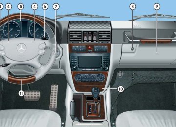
Controls in detail Useful features
Cup holder next to armrest
1 Cupholder 2 Cupholder base 왘 Place bracket of cup holder 1 into
recess (indicated by arrow) of cupholder base 2.
If the cup holder is no longer in use, it can for example, be stored in the glove box or storage compartment below the armrest.
219
Controls in detail Useful features
Cup holder in front passenger footwell
Cup holder in rear passenger footwell
Ashtrays
Your vehicle is equipped with an ashtray and a cigarette lighter located in the center console and two ashtrays located in the rear passenger compartment (컄 page 221).
Ashtray in the center console
1 Ashtray 2 Cigarette lighter (컄 page 222) 3 Cover plate
1 Cupholder 왘 Swing cupholder 1 upwards until it
clicks into place.
! Fold the cup holder closed before moving the front passenger seat fully forward.
Rear cup holder ! Before folding the seat backrest forward and the rear seat bench down, be sure that all containers in the rear cup holder are removed.
220
Opening the ashtray 왘 Briefly touch at top of cover plate 3.
The ashtray opens automatically.
Removing the ashtray insert
Warning!
Remove ashtray only with vehicle standing still. Set the parking brake to secure the vehicle from movement. Move gear selector lever to neutral position N. With the gear se- lector lever in neutral position N turn off the engine.
왘 Secure the vehicle from movement by
setting the parking brake.
왘 Move the gear selector lever to neutral
position N. Now you have more room to take out the ashtray insert. 왘 Turn off the engine.
4 Sliding button 5 Astray insert 왘 Push sliding button 4 to the right. Ashtray insert 5 disengages and protrudes a short distance.
왘 Remove ashtray insert 5 from ashtray
frame in direction of the arrow.
Controls in detail Useful features
Reinstalling the ashtray insert 왘 Push ashtray insert 5 down into the
ashtray frame until it engages.
왘 Push at top of cover plate 3 to close
the ashtray. Cover plate 3 engages.
Ashtrays in the rear passenger compartment There is located one ashtray on each rear passenger door.
1 Cover 2 Catch 3 Ashtray insert
221
Controls in detail Useful features
Opening the ashtray 왘 Pull at top of cover 1.
Removing the ashtray insert 왘 Push down on catch 2. 왘 Pull out ashtray insert 3.
Reinstalling the ashtray insert 왘 Position ashtray insert 3. 왘 Push at top of cover 1 to close the
ashtray.
222
Cigarette lighter
Warning!
Never touch the heating element or sides of the cigarette lighter; they are extremely hot. Hold the knob only.
Make sure that any children traveling with you do not injure themselves or start a fire with the hot cigarette lighter.
When leaving the vehicle, always remove the SmartKey from the starter switch, take it with you, and lock the vehicle. Do not leave children unattended in the vehicle, or with access to an unlocked vehicle. Unsuper- vised use of vehicle equipment may cause an accident and/or serious personal injury.
왘 Switch on the ignition (컄 page 39).
1 Cigarette lighter 왘 Briefly touch at top of the cover plate.
The ashtray opens automatically.
왘 Push in cigarette lighter 1.
The cigarette lighter will pop out automatically when hot.
! The lighter socket can accommodate 12 V DC electrical accessories (up to a maxi- mum of 180 W) designed for use with the stan- dard “cigarette lighter” plug type. Keep in mind, however, that connecting accessories to the lighter socket (for example extensive connecting and disconnecting, or using plugs that do not fit properly) can damage the lighter socket. With the socket damaged, the lighter may no longer be able to be placed in the heating (pushed-in) position, or the lighter may pop out too early with the lighter not hot enough. To help avoid damaging the cigarette lighter socket, we recommend connecting 12 V DC electrical accessories designed for use with the standard “cigarette lighter” plug type to the 12 V power outlets (컄 page 223) in your vehicle whenever possible.
i If the engine is off, and the cigarette lighter is being used extensively, the vehicle battery may become discharged.
Electrical outlet
! If you use all power outlets in the vehicle, make sure that the maximum current drawn does not exceed 15 A.
i The power outlets can be used to accommodate 12 V DC electrical accessories (e.g. auxiliary lamps) up to a maximum of 180 W. If the engine is off, the battery may become discharged if used for long periods of time.
Power outlets are located 앫 in the front passenger footwell
(컄 page 223)
앫 in the rear passenger footwell
(컄 page 224)
앫 on the left-hand side of the cargo
compartment (컄 page 224)
Controls in detail Useful features
Power outlet in front passenger footwell
왘 Switch on the ignition (컄 page 39). 왘 Flip up cover and insert electrical plug
(cigarette lighter type).
223
Controls in detail Useful features
Power outlet in rear passenger footwell
Power outlet in cargo compartment
Floormats
왘 Switch on the ignition (컄 page 39). 왘 Flip up cover and insert electrical plug
왘 Switch on the ignition (컄 page 39). 왘 Flip up cover and insert electrical plug
(cigarette lighter type).
(cigarette lighter type).
Warning!
Whenever you are using floormats, make sure there is enough clearance and the floormats are securely fastened.
Floormats should always be securely fas- tened using the eyelets and retainer pins.
Before driving off, check that the floormats are securely in place and adjust them if necessary. A loose floormat could slip and hinder proper functioning of the pedals.
Do not place several floormats on top of each other as this may impair pedal move- ment.
i To install or remove the floormat more easily, move the driver’s seat or front passenger seat as far to the rear as possible (컄 page 42).
224
Controls in detail Useful features
Switching on 왘 Switch on the ignition (컄 page 39). 왘 Turn switch at the tip of stalk in
direction of arrow 1. The steering wheel is heated. Indicator lamp 3 comes on.
i The steering wheel heating is temporarily suspended while the indicator lamp 3 remains on when 앫 the temperature of the vehicle interior is
above 86°F (30°C)
앫 the temperature of the steering wheel is
above 95°F (35°C)
When these conditions do not apply anymore, steering wheel heating continues.
Switching off 왘 Turn switch at the tip of stalk in
direction of arrow 2. The heated steering wheel is switched off. Indicator lamp 3 goes out.
i Indicator lamp 3 flashes or goes out 앫 in case of power surge or undervoltage 앫 in case of a steering wheel heating
malfunction
i The steering wheel heating switches off automatically when you remove the SmartKey from the starter switch.
For information on adjusting the steering wheel, see “Steering wheel” (컄 page 44).
Heated steering wheel
The steering wheel heating warms up the leather area of the steering wheel. The stalk is located on the lower left-hand side of the steering wheel.
1 Switching on 2 Switching off 3 Indicator lamp
225
Controls in detail Useful features
Telephone*
Warning!
Never operate radio transmitters equipped with a built-in or attached antenna (i.e. with- out being connected to an external antenna) from inside the vehicle while the engine is running. Doing so could lead to a malfunc- tion of the vehicle’s electronic system, possibly resulting in an accident and/or serious personal injury.
Radio transmitters, such as a portable tele- phone or a citizens band unit, should only be used inside the vehicle if they are con- nected to an antenna that is installed on the outside of the vehicle. The external antenna must be approved by Mercedes-Benz. Please contact an autho- rized Mercedes-Benz Light Truck Center for information on the installation of an approved external antenna. Refer to the radio transmitter operation instructions regarding use of an external antenna.
226
Warning!
Please do not forget that your primary responsibility is to drive the vehicle. A driver’s attention to the road must always be his/her primary focus when driving. For your safety and the safety of others, we recommend that you pull over to a safe location and stop before placing or taking a telephone call. If you choose to use the telephone1 while driving, please use the hands-free device and only use the telephone when road, weather and traffic conditions permit. Some jurisdictions prohibit the driver from using a mobile telephone while driving a vehicle. Only operate the COMAND system1 if road, weather and traffic conditions permit.
Bear in mind that at a speed of just 30 mph (approximately 50 km/h), your vehicle is covering a distance of 44 feet (approximately 14 m) every second.
1 Observe all legal requirements.
i Various mobile phone cradles can be installed in the front center armrest, see separate installation instructions for the mobile phone cradle. These mobile phone cradles can be obtained from an authorized Mercedes-Benz Light Truck Center. The functions and services available to you while using the mobile phone depend on your service provider and the type of mobile phone you are using. See also separate operating manual for instructions on how to use the mobile phone.
When the mobile phone is inserted in the cradle, you can operate the telephone using the following devices: 앫 mobile phone keypad 앫 COMAND system (see separate
operating instructions)
앫 buttons s and t on the multi- function steering wheel (컄 page 134) 앫 Voice Control System* (see separate
operating instructions)
Please note that these functions are only available with Mercedes-Benz approved mobile phones. Please contact an authorized Mercedes-Benz Light Truck Center for information on features avail- able for your mobile phone of choice. The cradle is located in the armrest. 왘 Open the telephone tray (컄 page 216).
Inserting mobile phone in mobile phone cradle Once the mobile phone has been inserted in the mobile phone cradle, you have to use the hands-free device to respond during phone calls.
! Do not try to remove the mobile phone along with the cradle. You could otherwise damage the mobile phone cradle.
왘 If applicable, remove the cover for the external antenna connection from the back of the mobile phone and store it in a safe place. Be sure to comply with the mobile phone’s operating instructions as well.
Example illustration 1 Inserting the mobile phone 2 Connector contact 3 Mobile phone cradle 왘 Slide the lower end of the mobile phone
into connector contact 2 on cradle 3.
Controls in detail Useful features
왘 Push the top of the mobile phone in
direction of arrow 1, until the lug on the mobile phone release button engages. The mobile phone is connected to the network via the external antenna. The mobile phone is linked to the hands-free device and the multi- function steering wheel. The battery is charged depending on its charge status and the position of the SmartKey in the starter switch. The charge procedure will be indicated in the mobile phone’s display.
You can place or receive phone calls. You can control other functions of the mobile phone via the control system (컄 page 159), the Voice Control System* (see separate operating instructions), or the COMAND system (see separate oper- ating instructions).
컄컄
227
Controls in detail Useful features
컄컄
i When you take the SmartKey out of the starter switch, the mobile phone remains switched on for approximately 10 minutes. If you place or receive a call during this time, the mobile phone switches off 10 minutes after the call has been completed.
Removing mobile phone from mobile phone cradle
왘 Press release catch in direction of
왘 Press release button in direction of
arrow 1 and take mobile phone out of mobile phone cradle 2.
arrow 1 and take mobile phone cradle 3 out in direction of arrow 2.
Installing a different mobile phone cradle
Changing mobile phone cradle If you require a different cradle for your mobile phone, remove the present cradle before installing a new one.
Removing an existing mobile phone cradle
Example illustration 1 Release catch for mobile phone 2 Mobile phone cradle
i When using a flip-style mobile phone, open flip top before removing from the cradle while a call is connected. Otherwise, the call will be disconnected.
228
Example illustration 1 To release the mobile phone cradle 2 To remove the mobile phone cradle 3 Mobile phone cradle
Example illustration 1 Contact plate 2 Recesses 3 Mobile phone cradle 왘 Insert mobile phone cradle 3 into
recesses 2 of contact plate 1.
왘 Push mobile phone cradle 3 forward
until it engages.
Tele Aid
! The initial activation of the Tele Aid system may only be performed by completing the sub- scriber agreement and placing an acquaintance call using the Information button ¡. Failure to complete either of these steps will result in a system that is not activated. If you have any questions regarding activation, please call the Response Center at 1-800-756-9018 (in the USA) or 1-888-923-8367 (in Canada).
Shortly after the completion of your Tele Aid acquaintance call, you will receive a user ID and password. By visiting www.mbusa.com and selecting “Tele Aid” (USA only), you will have access to account information, remote door unlock and more.
The Tele Aid system (Telematic Alarm Identification on Demand) The Tele Aid system consists of three types of response: 앫 automatic and manual emergency 앫 roadside assistance 앫 information The Tele Aid system is operational provid- ing that the vehicle’s battery is charged, properly connected, not damaged and cellular and GPS coverage are available. The speaker volume of a Tele Aid call can be adjusted by using the volume control on the COMAND system headunit or on the multifunction steering wheel. To raise, turn the rotary volume control on the COMAND system headunit clockwise or press button æ on the multifunction steering wheel. To lower, turn the rotary volume control on the COMAND system headunit counterclockwise or press button ç on the multifunction steering wheel.
Controls in detail Useful features
왘 To activate, press the SOS button, the
Roadside Assistance button • or the Information button ¡, depend- ing on the type of response required.
i The SOS button is located in the overhead control panel (컄 page 231). The Roadside Assistance button • (컄 page 232) and the Information button ¡ (컄 page 233) are located below the center armrest cover.
! The Tele Aid system utilizes the cellular network for communication and the GPS (Global Positioning System) satellites for vehicle location. If either of these signals are unavail- able, the Tele Aid system may not function and if this occurs, assistance must be summoned by other means.
229
Controls in detail Useful features
i When a Tele Aid call has been initiated, the COMAND system audio is muted and the selected mode (radio, CD etc.) pauses. The optional cellular phone (if installed) inserted in cradle switches off. If you must use this phone, we recommend that you use it only with the vehicle at a standstill in a safe location. Remove the phone from the cradle and place the call. The navigation system (if engaged) will con- tinue to run. The display in the instrument cluster is available for use, and spoken commands are only available by pressing the RPT button on the COMAND system. A pop-up window will appear in the COMAND system display to indicate that a Tele Aid call is in progress. After the Tele Aid call has ended, the optional cellular phone inserted in the cradle switches on again. A PIN entry might be necessary.
230
System self-check Initially, after switching on the ignition, malfunctions are detected and indicated (the indicator lamps in the SOS button, the Roadside Assistance button • and the Information button ¡ stay on longer than 10 seconds or do not come on). The message Tele Aid inoperative appears in the multifunction display.
Warning!
If the indicator lamps on the SOS button, on the Roadside Assistance button, and/or on the Information button remain illuminated continuously in red and/or the message Tele Aid inoperative is displayed in the multifunction display after the system self-check, a malfunction in the system has been detected.
If a malfunction is indicated as outlined above, the system may not operate as expected. Have the system checked at the nearest Mercedes-Benz Light Truck Center as soon as possible.
Emergency calls An emergency call is initiated auto- matically following an accident in which the emergency tensioning devices (ETDs) or air bags deploy. An emergency call can also be initiated manually by opening the cover next to the interior rear view mirror labeled SOS, then briefly pressing the button located under the cover. See (컄 page 231) for instructions on initiating an emergency call manually. Once the emergency call is in progress, the indicator lamp on the SOS button will begin to flash. The message Connecting call appears in the multifunction display. When the connection is established, the message Call connected appears in the multifunction display. All information relevant to the emergency, such as the location of the vehicle (determined by the GPS satellite location system), vehicle model, identification number and color are generated.
Warning!
If the indicator lamp in the SOS button is flashing continuously and there was no voice connection to the Response Center established, then the Tele Aid system could not initiate an emergency call (e.g. the rele- vant cellular phone network is not available). The message Call failed appears in the multifunction display for approximately 10 seconds.
Should this occur, assistance must be summoned by other means.
A voice connection between the Response Center and the occupants of the vehicle will be established automatically soon after the emergency call has been initiated. The Response Center will attempt to determine more precisely the nature of the accident provided they can speak to an occupant of the vehicle. The Tele Aid system is available if 앫 it has been activated and is
operational. Activation requires a subscription for monitoring services, connection and cellular air time
앫 vehicle battery power is available 앫 the relevant cellular phone network
and GPS signals are available and pass the information on to the Response Center
i Location of the vehicle on a map is only possible if the vehicle is able to receive signals from the GPS satellite network and pass the information on to the Response Center.
Controls in detail Useful features
Initiating an emergency call manually
1 Cover 2 SOS button 왘 Briefly press on cover 1.
The cover opens.
왘 Press SOS button 2 briefly.
The indicator lamp in SOS button 2 will flash until the emergency call is concluded.
컄컄
231
Controls in detail Useful features
컄컄
왘 Wait for a voice connection to the
Response Center.
왘 Close cover 1 after the emergency
call is concluded.
Roadside Assistance button • The Roadside Assistance button • is located below the center armrest cover.
Warning!
If you feel at any way in jeopardy when in the vehicle (e.g. smoke or fire in the vehicle, vehicle in a dangerous road location), please do not wait for voice contact after you have pressed the emergency button. Carefully leave the vehicle and move to a safe loca- tion. The Response Center will automatically contact local emergency officials with the vehicle’s approximate location if they receive an automatic SOS signal and cannot make voice contact with the vehicle occupants.
232
1 Button to open telephone tray 2 Armrest cover 3 Roadside Assistance button • 왘 Press button 1 and lift up armrest
cover 2.
왘 Press and hold button 3 (for longer
than 2 seconds). A call to a Mercedes-Benz Roadside Assistance dispatcher will be initiated. The button will flash while the call is in progress. The message Connecting call will appear in the multifunction display.
When the connection is established, the message Call connected appears in the multifunction display. The Tele Aid system will transmit data generating the vehicle identification number, model, color and location (subject to availability of cellular and GPS signals).
i While the call is connected you can change to the navigation menu by pressing the NAV button on the COMAND system headunit.
A voice connection between the Roadside Assistance dispatcher and the occupants of the vehicle will be established. 왘 Describe the nature of the need for
assistance.
The Mercedes-Benz Roadside Assistance dispatcher will either dispatch a qualified Mercedes-Benz technician or arrange to tow your vehicle to the nearest Mercedes-Benz Light Truck Center. For services such as labor and/or towing, charges may apply. Refer to the Roadside Assistance Manual for more information. The following is only available in the USA: 앫 Sign and Drive services: Services such as jump start, a few gallons of fuel or the replacement of a flat tire with the vehicle spare tire are obtainable.
i The indicator lamp on the Roadside Assistance button • remains illuminated in red for approximately 10 seconds during the system self-check after switching on the ignition (together with the SOS button and the Information button ¡). See system self-check (컄 page 230) if the indicator lamp does not come on in red or stays on longer than approximately 10 seconds. If the indicator lamp on the Roadside Assistance button • is flashing continuously and there was no voice connection to the Response Center established, then the Tele Aid system could not initiate a Roadside Assistance call (e.g. the rele- vant cellular phone network was not available). The message Call failed appears in the multifunction display. Roadside Assistance calls can be terminated using the t button on the multifunction steering wheel or the END button on the COMAND system headunit.
Controls in detail Useful features
Information button ¡ The Information button ¡ is located below the center armrest cover.
1 Button to open telephone tray 2 Armrest cover 3 Information button ¡ 왘 Press button 1 and lift up armrest
cover 2.
컄컄
233
Controls in detail Useful features
컄컄
왘 Press and hold button 3 (for longer
than 2 seconds). A call to the Customer Assistance Center will be initiated. The button will flash while the call is in progress. The message Connecting call will appear in the multifunction display.
When the connection is established, the message Call connected appears in the multifunction display. The Tele Aid system will transmit data generating the vehicle identification number, model, color and location (subject to availability of cellular and GPS signals).
i While the call is connected, you can change to the navigation menu by pressing the NAV button on the COMAND system headunit.
234
A voice connection between the Customer Assistance Center representative and the occupants of the vehicle will be estab- lished. Information regarding the operation of your vehicle, the nearest Mercedes-Benz Light Truck Center or Mercedes-Benz USA products and services is available to you. For more details concerning the Tele Aid system, please visit www.mbusa.com and use your ID and password (sent to you separately) to learn more (USA only).
i The indicator lamp in the Information button ¡ remains illuminated in red for approximately 10 seconds during the system self-check after switching on the ignition (together with the SOS button and the Roadside Assistance button •). See system self-check (컄 page 230) if the indicator lamp does not come on in red or stays on longer than approximately 10 seconds. If the indicator lamp in the Information button ¡ is flashing continuously and there was no voice connection to the Response Center established, then the Tele Aid system could not initiate an Information call (e.g. the relevant cellular phone network is not available). The message Call failed appears in the multifunction display. Information calls can be terminated using the t button on the multifunction steering wheel or the END button on the COMAND system headunit.
! If the indicator lamps do not start flashing after pressing one of the buttons or remain illuminated (in red) at any time, the Tele Aid system has detected a malfunction or the service is not currently active, and may not initiate a call. Visit your authorized Mercedes-Benz Light Truck Center and have the system checked or contact the Response Center at 1-800-756-9018 (in the USA) or 1-888-923-8367 (in Canada) as soon as possible.
Call priority If other service calls such as a Roadside Assistance call or Information call are active, an Emergency call is still possible. In this case, the Emergency call will take priority and override all other active calls.
i The indicator lamp in the respective button flashes until the call is concluded. Emergency calls can only be terminated by a Response Center or Customer Assistance Center repre- sentative, whereas Roadside Assistance and Information calls can also be terminated using the t button on the multifunction steering wheel or the END button on the COMAND system headunit.
! If the indicator lamp continues to flash or the system does not reset, contact the Response Center at 1-800-756-9018 (in the USA) or 1-888-923-8367 (in Canada), or Mercedes-Benz Customer Assistance at 1-800-FOR-MERCedes (1-800-367-6372) in the USA or Customer Service at 1-800-387-0100 in Canada.
Controls in detail Useful features
Remote door unlock In case you have locked your vehicle unin- tentionally (e.g. SmartKey inside vehicle), and the reserve SmartKey is not handy: 왘 Contact the Mercedes-Benz Response Center at 1-800-756-9018 (in the USA) or 1-888-923-8367 (in Canada). You will be asked to provide your pass- word which you provided when you completed the subscriber agreement. 왘 Then return to your vehicle at the time
arranged with the Response Center and press the tailgate lock for a minimum of 20 seconds until the SOS button is flashing. The message Connecting call appears in the multifunction display.
As an alternative, you may unlock the vehi- cle via Internet using the ID and password sent to you shortly after the completion of your acquaintance call.
235
Controls in detail Useful features
The Response Center will then unlock your vehicle with the remote door unlocking feature.
i The remote door unlock feature is available if the relevant cellular phone network is available. The SOS button will flash and the message Connecting call will appear in the multi- function display to indicate receipt of the door unlock command. Once the vehicle is unlocked, a Response Center specialist may attempt to establish voice contact with the vehicle occupants. If the tailgate lock was pressed for more than 20 seconds before door unlock authorization was received by the Response Center, you must wait 15 minutes before pressing the tailgate lock again.
236
Garage door opener
The integrated remote control is capable of operating up to three separately controlled devices. It provides a convenient way to replace up to three hand-held remote controls used to operate devices such as garage door openers, gate openers, or other devices compatible with HomeLink® or some other systems. Before the integrated remote control can be used, it must be programmed to the garage door opener, gate operator or other device you wish to operate. See the follow- ing instructions for programming informa- tion.
Stolen Vehicle Recovery services In the event your vehicle was stolen: 왘 Report the incident to the police. The police will issue a numbered incident report.
왘 Pass this number on to the
Mercedes-Benz Response Center along with your password issued to you when you subscribed to the service. The Response Center will then attempt to covertly contact the vehicle’s Tele Aid system. Once the vehicle is located, the Response Center will contact the local law enforcement and you. The vehicle’s location will only be provided to law enforcement.
i When the anti-theft alarm stays on for more than 30 seconds, a call is initiated automatically to the Response Center. For more information, see “Anti-theft systems” (컄 page 96).
Controls in detail Useful features
Warning!
When programming a garage door opener, park the vehicle outside the garage.
Do not run the engine while programming the integrated remote control. Inhalation of exhaust gas is hazardous to your health. All exhaust gas contains carbon monoxide (CO), and inhaling it can cause unconscious- ness and possible death.
Programming the integrated remote control Step 1: 왘 Switch on the ignition (컄 page 39).
컄컄
Before programming the integrated remote control to a garage door opener or gate operator, make sure people and objects are out of the way of the device to prevent potential harm or damage. When program- ming a garage door opener, the door moves up or down. When programming a gate oper- ator, the gate opens or closes.
Do not use the integrated remote control with any garage door opener that lacks safety stop and reverse features as required by U.S. federal safety standards (this includes any garage door opener model manufactured before April 1, 1982). A garage door that cannot detect an object - signaling the door to stop and reverse - does not meet current U.S. federal safety standards.
237
Indicator lamp
Interior rear view mirror with integrated remote control 2 3 4 Signal transmitter button Needed for programming (not part of vehicle equipment):
Hand-held remote control of garage door opener, gate operator or other device Hand-held remote control button
Controls in detail Useful features
컄컄
Step 2: 왘 If you have previously programmed a signal transmitter button and wish to retain its programming, proceed to step 3. If you are programming the integrated remote control for the first time, press and hold outer signal transmitter buttons 2 and 4 and release them only when indicator lamp 1 begins to flash after approximately 20 seconds (do not hold the button for longer than 30 seconds). This procedure erases any previous settings for all three channels and initializes the memory. If you later wish to program a second and/or third hand-held transmitter to the remaining two signal transmitter buttons, do not repeat this step and begin directly with step 3.
238
Step 3: 왘 Hold end of hand-held remote
control 5 of the device you wish to train approximately 2 to 5 in (5 to12 cm) away from signal trans- mitter button (2, 3 or 4) to be programmed, while keeping indicator lamp 1 in view.
Step 4: 왘 Using both hands, simultaneously
press hand-held remote control button 6 and the desired signal transmitter button (2, 3, or 4). Do not release the buttons until step 5 is completed. Indicator lamp 1 will flash, first slowly and then rapidly.
i Indicator lamp 1 flashes immediately the first time the signal transmitter button is programmed. If this button has already been programmed, the indicator lamp will only start flashing after 20 seconds.
Step 5: 왘 After indicator lamp 1 changes from a slow to a rapidly flashing light, release the hand-held remote control button and the signal transmitter button.
Step 6: 왘 Press and hold the just-trained signal transmitter button (2, 3, or 4) and observe indicator lamp 1. If indicator lamp 1 stays on constantly, programming is complete and your device should activate when the respective signal transmitter button (2, 3, or 4) is pressed and released.
i If indicator lamp 1 flashes rapidly for about 2 seconds and then turns to a constant light, continue with programming steps 8 through 12 as your garage door opener may be equipped with the “rolling code” feature.
Step 7: 왘 To program the remaining two signal transmitter buttons, repeat the steps above starting with step 3.
Rolling code programming To train a garage door opener (or other rolling code devices) with the rolling code feature, follow these instructions after completing the “Programming” portion (steps 1 through 6) of this text. (A second person may make the following training procedures quicker and easier.) Step 8: 왘 Locate “training” button on the garage
door opener motor head unit. Exact location and color of the button may vary by garage door opener brand. Depending on manufacturer, the “training” button may also be referred to as “learn” or “smart” button. If there is difficulty locating the transmitting button, refer to the garage door opener Operator’s manual.
Step 9: 왘 Press the “training” button on the
garage door opener motor head unit. The “training light” is activated. You have 30 seconds to initiate the following steps. Step 10: 왘 Return to the vehicle and firmly press,
hold for 2 seconds and release the programmed signal transmitter button (2, 3, or 4).
Step 11: 왘 Press, hold for 2 seconds and release
same signal transmitter button a second time to complete the training process.
i Some garage door openers (or other rolling code equipped devices) may require you to press, hold for 2 seconds and release the same signal transmitter button a third time to complete the training process.
Controls in detail Useful features
Step 12: 왘 Confirm the garage door operation by
pressing the programmed signal transmitter button (2, 3, or 4).
Step 13: 왘 To program the remaining two signal transmitter buttons, repeat the steps above starting with step 3.
Gate operator/Canadian programming Canadian radio-frequency laws require transmitter signals to “time-out” (or quit) after several seconds of transmission which may not be long enough for the integrated signal transmitter to pick up the signal during programming. Similar to this Canadian law, some U.S. gate operators are designed to “time-out” in the same manner.
239
Controls in detail Useful features
If you live in Canada or if you are having difficulties programming a gate operator (regardless of where you live) by using the programming procedures, replace step 4 with the following: Step 4: 왘 Press and hold the signal transmitter button (2, 3, or 4). Do not release this button until it has been success- fully trained.
왘 While still holding down the signal transmitter button (2, 3 or 4), “cycle” your hand-held remote control button 6 as follows: Press and hold button 6 for 2 seconds, then release it for 2 seconds, and again press and hold it for 2 seconds. Repeat this sequence on the hand-held remote control until the frequency signal has been learned. Upon successful train- ing, indicator lamp 1 will flash slowly and then rapidly after several seconds. 왘 Proceed with programming step 5 and
step 6 to complete.
240
i Upon completion of programming the integrated remote control, make sure you retain the hand-held remote control that came with the garage door opener, gate operator or other device. You may need it for use in other vehicles, for future programming of an integrated remote control, or simply for continued use as a hand-held remote control to operate the respective device in other situations.
Reprogramming a single signal transmitter button To program a device using a signal trans- mitter button previously trained, follow these steps: 왘 Switch on the ignition (컄 page 39). 왘 Press and hold the desired signal transmitter button (2, 3, or 4). Do not release the button.
왘 Indicator lamp 1 will begin to flash
after 20 seconds. Without releasing the signal transmitter button, proceed with programming starting with step 3.
Operation of integrated remote control 왘 Switch on the ignition (컄 page 39). 왘 Select and press the appropriate signal
transmitter button (2, 3, or 4) to activate the remote controlled device. The integrated remote control transmitter continues to send the signal as long as the button is pressed – up to 20seconds.
Erasing the integrated remote control memory 왘 Switch on the ignition (컄 page 39). 왘 Simultaneously press and hold outer signal transmitter buttons 2 and 4, for approximately 20 seconds, until indicator lamp 1 blinks rapidly. Do not hold for longer than 30 seconds. The codes of all three channels are erased.
i If you sell your vehicle, erase the codes of all three channels.
Programming tips If you are having difficulty programming the integrated remote control, here are some helpful tips: 앫 Check the frequency of hand-held
remote control 5 (typically located on the reverse side of the remote). The integrated remote control is compati- ble with radio-frequency devices oper- ating between 280-390 MHz.
앫 Put a new battery in hand-held remote
control 5. This will increase the likelihood of the hand-held remote con- trol sending a faster and more accurate signal to the integrated remote control.
앫 While performing step 3, hold
hand-held remote control 5 at different lengths and angles from the signal transmitter button (2, 3 or 4) you are programming. Attempt varying angles at the distance of 2 to 5 in (5 to 12 cm) away or the same angle at varying distances.
앫 If another hand-held remote control is available for the same device, try the programming steps again using that other hand-held remote control. Make sure new batteries are in the hand-held remote control before beginning the procedure.
앫 Straighten the antenna wire from the
garage door opener assembly. This may help improve transmitting and/or receiving signals.
i Certain types of garage door openers are incompatible with the integrated remote control. If you should experience further difficulties with programming the integrated remote control, contact an authorized Mercedes-Benz Light Truck Center, or call Mercedes-Benz Customer Assistance Center (in the USA only) at 1-800-FOR-MERCedes, or Customer Service (in Canada) at 1-800-387-0100.
Controls in detail Useful features
i USA only: This device complies with Part 15 of the FCC Rules. Operation is subject to the following two conditions: (1) This device may not cause harmful inter-
ference, and
(2) this device must accept any interference received, including interference that may cause undesired operation.
Any unauthorized modification to this device could void the user’s authority to operate the equipment.
i Canada only: This device complies with RSS-210 of Industry Canada. Operation is subject to the following two conditions: (1) This device may not cause interference, and (2) this device must accept any interference received, including interference that may cause undesired operation of the device. Any unauthorized modification to this device could void the user’s authority to operate the equipment.
241
242
Operation
The first 1000 miles (1500 km) Driving instructions At the gas station Engine compartment Tires and wheels Winter driving Maintenance Vehicle care
243
Operation The first 1000 miles (1500 km)
In the “Operation” section you will find detailed information on operating, main- taining and caring for your vehicle.
244
The more cautiously you treat your vehicle during the break-in period, the more satis- fied you will be with its performance later on. 앫 Drive your vehicle during the first
1000 miles (1500 km) at varying but moderate vehicle and engine speeds. 앫 During this period, avoid heavy loads
(full throttle driving) and excessive engine speeds (no more than 2/3 of maximum rpm in each gear).
앫 Shift gears in a timely manner. 앫 Avoid accelerating by kick-down. 앫 Do not attempt to slow the vehicle
down by shifting to a lower gear using the gear selector lever.
앫 Select gear ranges 3, 2, or 1
(컄 page 167) only when driving at moderate speeds (for hill driving). After 1000 miles (1500 km) you may gradually increase vehicle and engine speeds to the permissible maximum.
! Additional instructions for AMG vehicles: 앫 During the first 1000 miles (1500 km), do not exceed a speed of 85 mph (140 km/h).
앫 During this period, avoid engine speeds
above 4500 rpm in each gear.
i G 55 AMG: For better protection of the front and rear differ- ential, the oil must be changed after a break-in period of 1900 miles (3000 km). Changing the oil in the front and rear differential increases the service life and helps reduce noise from the differential locks. See Maintenance Booklet for additional infor- mation and Factory Approved Service Products pamphlet (USA only) for information on the approved service product required to perform the front and rear axle oil change.
All of the above instructions, as may apply to your vehicle type, also apply when driving the first 1000 miles (1500 km) after the engine, the transfer case, the front differential or the rear differential has been replaced.
i Always obey applicable speed limits.
Operation Driving instructions
Drinking and driving
Pedals
Warning!
Warning!
Drinking and driving and/or taking drugs and driving are very dangerous combina- tions. Even a small amount of alcohol or drugs can affect your reflexes, perceptions and judgment.
The possibility of a serious or even fatal accident are greatly increased when you drink or take drugs and drive.
Do not drink or take drugs and drive or allow anyone to drive who has been drinking or taking drugs.
Make sure that absolutely no objects are obstructing the pedal’s range of movement. Keep the driver’s footwell clear of all obsta- cles. If there are any floormats or carpets in the footwell, make sure that the pedals still have sufficient clearance.
During sudden driving or braking maneu- vers, the objects could get caught between the pedals. You could then no longer brake or accelerate. This could lead to accidents and injury.
왔 Driving instructions Drive sensibly – save fuel
Fuel consumption, to a great extent, depends on driving habits and operating conditions. To save fuel you should: 앫 Keep tires at the recommended infla-
tion pressures.
앫 Remove unnecessary loads. 앫 Allow engine to warm up under low
load use.
앫 Avoid frequent acceleration and decel-
eration.
앫 Have all maintenance work performed
at the intervals specified in the Maintenance Booklet and as required by the Maintenance System. Contact an authorized Mercedes-Benz Light Truck Center.
Fuel consumption is also increased by driving in cold weather, in stop-and-go traffic, on short trips and in hilly area.
245
Operation Driving instructions
Power assistance
Warning!
With the engine not running, there is no power assistance for the brake and steering systems. In this case, it is important to keep in mind that a considerably higher degree of effort is necessary to brake and steer the vehicle.
Brakes
Warning!
After driving in heavy rain for some time without applying the brakes or through water deep enough to wet brake compo- nents or salty road conditions, the first brak- ing action may be somewhat reduced and increased pedal pressure may be necessary to obtain expected braking effect. Maintain a safe distance from vehicles in front.
246
To help prevent brake disk corrosion after driving on wet road surfaces (particularly salted roads), it is advisable to brake the vehicle with considerable force prior to parking. The heat generated serves to dry the brakes. If your brake system is normally only subjected to moderate loads, you should occasionally test the effectiveness of the brakes by applying above-normal braking pressure at higher speeds. This will also enhance the grip of the brake pads.
Warning!
Make sure not to endanger any other road users when carrying out these braking maneuvers.
Resting your foot on the brake pedal will cause excessive and premature wear of the brake pads.
It can also result in the brakes overheating, thereby significantly reducing their effec- tiveness. It may not be possible to stop the vehicle in sufficient time to avoid an acci- dent.
! Operational or performance test must only be conducted on a two-axle dynamometer. If such tests are necessary, contact an authorized Mercedes-Benz Light Truck Center. You could otherwise seriously damage the brake system or the transfer case which is not covered by the Mercedes-Benz Limited Warranty.
! Because the ESP® operates automatically, the engine and ignition must be shut off (SmartKey in starter switch position 0 or 1) when testing the parking brake on a brake test dynamometer and such testing should be no longer than 10 seconds. Active braking action through the ESP® may otherwise seriously damage the brake system which is not covered by the Mercedes-Benz Limited Warranty.
Operation Driving instructions
Refer to the description of the Brake Assist System (BAS) (컄 page 90). Brake pad wear or a leak in the system may be the reason for low brake fluid in the reservoir. The brake fluid level in the reservoir may be too low if the brake warning lamp in the instrument cluster comes on although the parking brake is released (컄 page 326). Observe additional messages in the multifunction display that may appear (컄 page 338). Have the brake system inspected immediately. Contact an authorized Mercedes-Benz Light Truck Center. All checks and service work on the brake system should be carried out by qualified technicians only. Contact an authorized Mercedes-Benz Light Truck Center. Only install brake pads and brake fluid recommended by Mercedes-Benz.
Warning!
Driving off
If other than recommended brake pads are installed, or other than recommended brake fluid is used, the braking properties of the vehicle can be degraded to an extent that safe braking is substantially impaired. This could result in an accident.
! When driving down long and steep grades, relieve the load on the brakes by shifting into a lower gear to use the engine’s braking power. This helps prevent overheating of the brakes and reduces brake pad wear.
After hard braking, it is advisable to drive on for some time, rather than immediately park, so the air stream will cool down the brakes faster.
Apply the brakes to test them briefly after driving off. Perform this procedure only when the road is clear of other traffic. Warm up the engine smoothly. Do not place full load on the engine until the operating temperature has been reached.
! When driving off on a slippery surface, do not allow a drive wheel to spin for an extended period with the ESP® switched off. Doing so may cause serious damage to the drivetrain which is not covered by the Mercedes-Benz Limited Warranty.
! Simultaneously depressing the accelerator pedal and applying the brake reduces engine performance and causes premature brake and drivetrain wear.
To ensure sufficient traction during off-road driving, activate differential locks as needed (컄 page 175).
247
Operation Driving instructions
Parking
Warning!
Do not park this vehicle in areas where com- bustible materials such as grass, hay or leaves can come into contact with the hot exhaust system, as these materials could be ignited and cause a vehicle fire.
248
To reduce the risk of personal injury or damage to the vehicle drivetrain as a result of vehicle movement, before turning off the engine and leaving the vehicle always: 앫 Keep right foot on brake pedal. 앫 Pull the parking brake lever up as many
notches as possible.
앫 Move the gear selector lever to park
position P.
앫 Slowly release brake pedal. 앫 When parked on an incline, turn front
wheel towards the road curb.
앫 Turn the SmartKey in the starter switch to position 0 and remove the SmartKey from the starter switch.
앫 Take the SmartKey with you and lock
vehicle when leaving.
Tires
Warning!
If you feel a sudden significant vibration or ride disturbance, or you suspect that possi- ble damage to your vehicle has occurred, you should turn on the hazard warning flash- ers, carefully slow down, and drive with cau- tion to an area which is a safe distance from the road.
Inspect the tires and the vehicle underbody for possible damage. If the vehicle or tires appear unsafe, have it towed to the nearest Mercedes-Benz Light Truck Center or tire dealer for repairs.
Specified tire inflation pressures must be maintained. This applies particularly if the tires are subjected to high loads (e.g. high speeds, heavy loads, high ambient temper- atures).
Warning!
Do not drive with a flat tire. A flat tire affects the ability to steer or brake the vehicle. You may lose control of the vehicle. Continued driving with a flat tire or driving at high speed with a flat tire will cause excessive heat build-up and possibly a fire.
For more information, see “Tires and wheels” (컄 page 277).
Treadwear indicators (TWI) are required by law. These indicators are located in six places on the tread circumference and become visible at a tread depth of approximately 1/16 in (1.6 mm), at which point the tire is considered worn and should be replaced. The treadwear indicator appears as a solid band across the tread.
Warning!
Although the applicable federal motor vehicle safety laws consider a tire to be worn when the treadwear indicators (TWI) become visible at approximately 1/16 in (1.6 mm), we recommend that you do not allow your tires to wear down to that level. As tread depth approaches 1/8 in (3.0 mm), the adhesion properties on a wet road are sharply reduced.
Depending upon the weather and/or road surface (conditions), the tire traction varies widely.
Operation Driving instructions
Hydroplaning
Depending on the depth of the water layer on the road, hydroplaning may occur, even at low speeds and with new tires. Reduce vehicle speed, avoid track grooves in the road and apply brakes cautiously in the rain.
Tire traction
The safe speed on a wet, snow covered or icy road is always lower than on a dry road. You should pay particular attention to the condition of the road whenever the outside temperatures are close to the freezing point.
Warning!
If ice has formed on the road, tire traction will be substantially reduced. Under such weather conditions, drive, steer and brake with extreme caution.
249
Operation Driving instructions
Mercedes-Benz recommends winter tires (컄 page 309) with a minimum tread depth of approximately 1/6 in (4 mm) on all four wheels for the winter season to ensure normal balanced handling characteristics. On packed snow, they can reduce your stopping distance compared with summer tires. Stopping distance, however, is still consid- erably greater than when the road is not covered with snow or ice. Exercise appro- priate caution.
! Avoid spinning of a drive wheel. This may cause serious damage to the drivetrain which is not covered by the Mercedes-Benz Limited Warranty.
Tire speed rating
Regardless of the tire speed rating, local speed limits should be obeyed. Use pru- dent driving speeds appropriate to prevail- ing conditions.
Warning!
Even when permitted by law, never operate a vehicle at speeds greater than the maxi- mum speed rating of the tires.
Exceeding the maximum speed for which tires are rated can lead to sudden tire failure, causing loss of vehicle control and possibly resulting in an accident and/or serious injury and possible death, for you and for others.
Your vehicle is factory equipped with “V”-rated tires, which have a speed rating of 149 mph (240 km/h). An electronic speed limiter prevents your vehicle from exceeding a speed of 130 mph (210 km/h).
i For information on speed rating for winter tires, see “Winter tires” (컄 page 309). For additional general information on tire speed markings on the tire sidewall, see “Tire speed rating” (컄 page 306).
250
Winter driving instructions
The most important rule for slippery or icy roads is to drive sensibly and to avoid abrupt acceleration, braking and steering maneuvers. Do not use the cruise control system under such conditions. When the vehicle is in danger of skidding, move the gear selector lever to neutral position N. Try to keep the vehicle under control by corrective steering action.
i For information on driving with snow chains, see “Snow chains” (컄 page 310).
Warning!
On slippery road surfaces, never downshift in order to obtain braking action. This could result in drive wheel slip and reduced vehi- cle control. Your vehicle’s ABS will not pre- vent this type of control loss.
Do not engage the transfer case in position LOW when driving on ice or packed snow. At speeds below 18 mph (30 km/h) vehicle steering is adversely affected by the LOW RANGE – ABS (컄 page 90).
Road salts and chemicals can adversely affect braking efficiency. Increased pedal force may become necessary to produce the normal brake effect. Depressing the brake pedal periodically when traveling at length on salt-strewn roads can bring road-salt-impaired braking efficiency back to normal. If the vehicle is parked after being driven on salt-treated roads, the braking efficiency should be tested as soon as possible after driving is resumed.
Warning!
Make sure not to endanger any other road users when carrying out these braking maneuvers.
Operation Driving instructions
Warning!
If the vehicle becomes stuck in snow, make sure that snow is kept clear of the exhaust pipe and from around the vehicle with the engine running. Otherwise, deadly carbon monoxide (CO) gases may enter vehicle interior resulting in unconsciousness and death.
To assure sufficient fresh air ventilation, open a window slightly on the side of the vehicle not facing the wind.
Warning!
The outside temperature indicator is not designed to serve as an ice-warning device and is therefore unsuitable for that purpose. Indicated temperatures just above the freezing point do not guarantee that the road surface is free of ice.
For more information, see “Winter driving” (컄 page 309).
251
Operation Driving instructions
Standing water
To prevent water from entering the passenger compartment or the engine compartment if you must drive through standing water, keep in mind 앫 the maximum depth of the water may
not exceed 19 in (48 cm)
앫 you must drive slowly
! Do not drive through flooded areas or water of unknown depth. Before driving through water, determine its depth. Never accelerate before driving into water. The bow wave could force water into the engine and auxiliary equipment, thus damaging them. If you must drive through standing water, drive slowly to prevent water from entering the passenger compartment or the engine compartment.
252
Water in these areas could cause 앫 damage to electrical components 앫 wiring of the engine or transmission or could result 앫 in water being ingested by the engine through the air intake, causing severe internal engine damage.
Any such damage is not covered by the Mercedes-Benz Limited Warranty. For more information, see “Driving through water” (컄 page 257).
Passenger compartment
Warning!
Always fasten items being carried as securely as possible.
In an accident, during hard braking or sud- den maneuvers, loose items will be thrown around inside the vehicle, and cause injury to vehicle occupants unless the items are securely fastened in the vehicle.
The rear cargo compartment is the preferred place to carry objects. Always use cargo tie-down rings, and if so equipped, always use partition net* when transporting cargo. The partition net* cannot secure hard or heavy objects. Always fasten items being carried as securely as possible using the cargo tie-down rings in the cargo compart- ment floor and fastening materials.
Do not load items on the roof. It may cause instability during some maneuvers which could result in an accident. This vehicle is not intended to carry items on its roof. Thus roof rails and roof mounted ski or bike holders must not be used.
Warning!
Sand, dirt, mud and other material having friction property can cause exceptional wear and tear as well as brake failure.
Have the brakes checked for dirt build-up and cleaned. There is otherwise a risk that full braking power may not be available in an emergency.
Read this chapter carefully before you begin off-road travel. Familiarize yourself with the vehicle characteristics and gear changing before you attempt any difficult terrain off-road driving. We recommend that you start out with easy off-road travel.
Off-road driving
Warning!
Do not load items on the roof. It may cause instability during some maneuvers which could result in an accident.
Drive slowly in unknown terrain. This will make it easier to recognize unexpected obstacles and avoid damage to the vehicle.
To help avoid the vehicle rolling over, never turn it around on steep inclines. If the vehi- cle cannot complete the attempted climb, back it down in reverse gear.
Do not drive along the side of a slope. The vehicle might otherwise rollover. If in doing so the vehicle begins to show a tendency to roll, immediately steer into a line of gravity (straight up or downhill).
Never let the vehicle roll backwards in idle. You may lose control of the vehicle if you use only the brake. For information on driving downhill, see “Driving downhill” (컄 page 257).
Operation Driving instructions
Special driving features for off-road driving The following driving features are available for specific kind of operation: 앫 ABS (컄 page 88) 앫 ESP® (컄 page 92) 앫 4-ETS (컄 page 91) 앫 Differential lock (컄 page 173) 앫 Transfer case (컄 page 170)
Off-road driving rules 왘 Engage the transfer case in position LOW before driving under off-road conditions (컄 page 170).
왘 If necessary activate differential locks
(컄 page 175). The ABS, BAS and ESP® are switched off automatically when the differential locks are activated.
왘 Fasten items being carried as securely
as possible (컄 page 208).
253
Operation Driving instructions
! Observe the following during off-road driving: 앫 Keep doors, tailgate, windows, and
tilt/sliding sunroof closed. 앫 Switch cruise control off. 앫 Adjust vehicle speed to condition of terrain.
The more uneven, rutty, and steeper the terrain, the lower the speed should be. Drive through water slowly at an even speed, avoiding a bow wave.
앫 Be especially careful when driving in
unknown territory. It may be necessary to get out of the vehicle and scout the path you intend to take.
앫 Watch out for obstacles, such as rocks,
holes, tree stumps, and ruts.
앫 Avoid excessive engine speeds – drive at moderate engine speeds (max. 3000 rpm). 앫 Before driving through water, determine its
depth.
앫 Do not stop vehicle while immersed in water,
and do not shut off the engine.
앫 In sandy soil, drive at a steady speed as
allowed by conditions. This helps overcome the vehicle rolling resistance and reduces the likelihood of the vehicle sinking into the ground.
앫 Do not initiate jumps with the vehicle. It interrupts the forward momentum of the vehicle.
앫 Always drive on slopes with the engine
running and the vehicle in gear.
앫 Inspect the vehicle for possible damage after
each off-road trip.
Warning!
Do not reduce the tire inflation pressure before driving through sand. However, if you do so, remember to correct the tire inflation pressure (컄 page 288) before continuing your trip. Driving with reduced tire inflation pressure increases the risk of losing control of the vehicle and rolling over.
Checklist before off-road driving
Engine oil level 앫 Check the engine oil level with the control system (컄 page 270). The message Engine oil level OK must appear in the multifunction display. Only then can the vehicle obtain a trouble-free oil supply, even on steep gradients.
! If a engine oil level warning message (컄 page 351) appears in the multifunction display while driving, stop the vehicle in a safe location or as soon at is safe to do so. Check the engine oil level (컄 page 270). The engine oil level warning messages should not be ignored. Extended driving with the message displayed could result in serious engine damage that is not covered by the Mercedes-Benz Limited Warranty.
254
Tires 앫 Check the tread depth and maintain specified tire inflation pressure (the Tire and Loading Information placard with the recommended tire inflation pressures is located on the driver’s door B-pillar (컄 page 280)).
앫 Check tires for possible damage and
remove foreign objects.
앫 Replace missing valve caps.
Rims 앫 Dented or bent rims can cause tire
inflation pressure loss and damage the tire beads. For this reason, check and, if necessary, change rims before driving off-road.
Vehicle tool kit 앫 Check if the vehicle jack (컄 page 367)
is functional.
앫 In all cases take the vehicle tool kit,
a strong tow rope, a shovel, and a small plank (to put under the vehicle jack on sandy soil) with you.
Operation Driving instructions
Driving in steep terrain
Slope angle 1 Overhang angle, front, 37° 2 Overhang angle, rear, 31° 앫 Comply with the warnings
(컄 page 253) and rules for off-road driving (컄 page 253).
255
Operation Driving instructions
앫 Driving on embankments, slopes and
앫 Utilize the engine’s braking power
other steep inclines should only be done straight uphill or downhill, i.e. in the line of gravity. Maximum vehicle climbing ability is a 80% grade which is equivalent to a slope angle of approxi- mately 38 degrees. Keep in mind that the climbing ability of the vehicle depends on terrain conditions.
앫 Select gear range 2 or 1 on the auto-
matic transmission (컄 page 167).
앫 Drive slowly.
when descending a slope, observe the engine speed (do not overrev the engine). Apply the service brake as needed.
i For maximum engine speed, see “Instru- ment cluster” (컄 page 26) and see “Engine” (컄 page 415). 앫 Check the brakes after a lengthy
downgrade drive.
Warning!
Never turn the vehicle around on steep inclines. The vehicle might roll over. If the vehicle cannot complete the attempted climb, back it down in reverse gear.
Traction in steep terrain Be easy on the accelerator and watch for continuous wheel traction when driving uphill.
i The 4-ETS helps greatly when starting out on a steep incline when the front wheels have then the tendency to slip due to the weight shifting away from the front axle. The 4-ETS recognizes the situation and limits the torque for the front wheels by braking them. Simultaneously the torque for the rear wheels is provided.
256
Driving across a hilltop Decelerate just ahead of a hilltop (do not select gear range N), to prevent the vehicle from speeding up too much after climbing a hill. Use the momentum of the vehicle to drive across the hilltop. After climbing a hill, driving in this manner prevents the vehicle from: 앫 loosing ground contact when cresting
hills
앫 loosing its forward momentum 앫 speeding up too much after climbing
the hill
Driving downhill 앫 Select gear range 1 on the automatic
transmission (컄 page 167).
앫 Drive downhill observing the same rules as driving uphill (컄 page 255).
! Only apply the service brake if the vehicle is travelling straight downhill, i.e. in the line of gravity.
i The special LOW RANGE – ABS setting allows for precise and brief (cyclical) blocking of the front wheels, permitting them to dig into loose ground. Remember that, when stopped, the front wheels slide across a surface and thus lose their ability to steer the vehicle.
Operation Driving instructions
Driving through water
1 Fording depth, 19.6 in (50 cm) 앫 Before driving through water,
determine its depth.
! The water depth must not exceed 19.6 in (50 cm). The ground under the water might not be firm which could result the water being deeper than expected when driving the vehicle through it. Please note that the water level is correspondingly lower for flowing water.
257