- 2001 Mercedes-Benz E Class Wagon Owners Manuals
- Mercedes-Benz E Class Wagon Owners Manuals
- 2002 Mercedes-Benz E Class Wagon Owners Manuals
- Mercedes-Benz E Class Wagon Owners Manuals
- 2007 Mercedes-Benz E Class Wagon Owners Manuals
- Mercedes-Benz E Class Wagon Owners Manuals
- 2006 Mercedes-Benz E Class Wagon Owners Manuals
- Mercedes-Benz E Class Wagon Owners Manuals
- 2005 Mercedes-Benz E Class Wagon Owners Manuals
- Mercedes-Benz E Class Wagon Owners Manuals
- 2003 Mercedes-Benz E Class Wagon Owners Manuals
- Mercedes-Benz E Class Wagon Owners Manuals
- Download PDF Manual
-
Only drive with the tailgate closed as, among other dangers such as blocked visi- bility, exhaust fumes may enter the vehicle interior.
Do not place the SmartKey in the open cargo compartment. You may lock yourself out.
If the vehicle was previously centrally locked, the tailgate will lock automati- cally after closing it. To confirm locking all turn signal lamps flash three times.
124
Controls in detail Locking and unlocking
You can also close the tailgate by hand.
Warning!
If the tailgate comes into contact with an object while closing (e.g. luggage that has been piled too high), the closing procedure is stopped and the tailgate reopens slightly.
To prevent a possible inadvertent lock- out, the tailgate will open automatically if a SmartKey with KEYLESS-GO is rec- ognized inside the vehicle.
Monitor the closing procedure carefully to make sure no one is in danger of being in- jured. To prevent possible personal injury, always keep hands and fingers away from the cargo compartment opening when clos- ing the tailgate. Be especially careful when small children are around. To stop the clos- ing procedure, do one of the following: 앫 press KEYLESS-GO locking/closing
switch 1 (컄 page 126)
앫 press the tailgate closing switch 1
(컄 page 125)
앫 press button Š on the SmartKey with
KEYLESS-GO (컄 page 111)
앫 pull the remote tailgate switch (on the
driver’s door) (컄 page 121)
컄컄
Closing the tailgate from the outside (vehicles with KEYLESS-GO*) In vehicles with tailgate opening/closing system* you can close the tailgate sepa- rately from the outside using the tailgate closing switch.
1 Tailgate closing switch 왘 Make sure you have the SmartKey with
KEYLESS-GO with you.
왘 Press tailgate closing switch 1 briefly.
The tailgate closes.
125
Controls in detail Locking and unlocking
컄컄
Even with the SmartKey with KEYLESS-GO removed from the vehicle, the tailgate clos- ing switch can be operated. Therefore, do not leave children unattended in the vehicle, or with access to an unlocked vehicle. Unsu- pervised use of vehicle equipment may cause an accident and/or serious personal injury.
Closing the tailgate and locking the vehicle from the outside (vehicles with KEYLESS-GO*) In vehicles with tailgate opening/closing system* and KEYLESS-GO, you can close the tailgate and lock the vehicle simulta- neously from the outside using the KEYLESS-GO locking/closing switch.
Warning!
Only drive with the tailgate closed as, among other dangers such as blocked visi- bility, exhaust fumes may enter the vehicle interior.
If the vehicle was previously centrally locked, the tailgate will lock automati- cally after closing it. To confirm locking all turn signal lamps flash three times.
126
1 KEYLESS-GO locking/closing switch 왘 Make sure you have SmartKey with
KEYLESS-GO with you.
왘 Press switch 1 briefly. 앫 The tailgate closes. 앫 All turn signal lamps flash three
times.
앫 The locking knobs in the doors
move down.
앫 The anti-theft alarm system is
armed.
You can also close the tailgate by hand.
If the tailgate comes into contact with an object while closing (e.g. luggage that has been piled too high), the closing procedure is stopped and the tailgate reopens slightly.
To prevent a possible inadvertent lock- out, the tailgate will open automatically if a SmartKey with KEYLESS-GO is rec- ognized inside the vehicle.
Warning!
Monitor the closing procedure carefully to make sure no one is in danger of being in- jured. To prevent possible personal injury, always keep hands and fingers away from the cargo compartment opening when clos- ing the tailgate. Be especially careful when small children are around. To stop the clos- ing procedure, do one of the following: 앫 press KEYLESS-GO locking/closing
switch 1
앫 press tailgate closing switch 1
(컄 page 125)
앫 press button Š on the SmartKey with
KEYLESS-GO (컄 page 111)
앫 pull the remote tailgate switch (on the
driver’s door) (컄 page 121)
Even with the SmartKey with KEYLESS-GO removed from the vehicle, the locking/clos- ing switch can be operated. Therefore, do not leave children unattended in the vehicle,
or with access to an unlocked vehicle. Unsu- pervised use of vehicle equipment may cause an accident and/or serious personal injury.
Warning!
Only drive with the tailgate closed as, among other dangers such as blocked visi- bility, exhaust fumes may enter the vehicle interior.
Automatic central locking
The doors and the tailgate automatically lock when the ignition is switched on and the wheels are turning at vehicle speeds of approximately 9 mph (15 km/h) or more. You can open a locked door from the in- side. Open door only when conditions are safe to do so.
Controls in detail Locking and unlocking
The doors unlock automatically after an accident if the force of the impact ex- ceeds a preset threshold. The vehicle automatically locks when the ignition is switched on and the wheels are turning at vehicle speeds of approximately 9 mph (15 km/h) or more. You could therefore lock yourself out when the vehicle 앫 is pushed or towed 앫 is on a test stand
For more information on towing the vehi- cle, see “Towing the vehicle” (컄 page 458). You can deactivate the automatic locking mode using the control system (컄 page 176).
127
Controls in detail Locking and unlocking
Locking and unlocking from the inside
The switch is located in the center console.
You can lock or unlock the doors and the tailgate from inside using the central lock- ing switch. This can be useful, for example, if you want to lock the vehicle before start- ing to drive. The fuel filler flap cannot be locked or un- locked with the central locking switch.
Warning!
When leaving the vehicle, always remove the SmartKey or the SmartKey with KEYLESS-GO* from the starter switch, take it with you, and lock the vehicle. Do not leave children unattended in the vehicle, or with access to an unlocked vehicle. Unsu- pervised use of vehicle equipment may cause an accident and/or serious personal injury.
128
Central locking switch 1 Locking 2 Unlocking
You can open a locked door from the inside. Open door only when conditions are safe to do so. If the vehicle was previously centrally locked using the SmartKey, it will not unlock using the central locking switch.
If the vehicle was previously locked with the central locking switch 앫 while in the selective remote con-
trol mode, only the front door opened from the inside is unlocked. 앫 while in the global remote control mode, the vehicle is unlocked com- pletely when a front door is opened from the inside.
Locking 왘 Press lower half 1 of the central lock-
ing switch. If all doors are closed, the vehicle locks.
Unlocking 왘 Press upper half 2 of the central lock-
ing switch. The vehicle unlocks.
For removal of the active head restraints we recommend that you contact an autho- rized Mercedes-Benz Center.
Adjust the head restraint in such a way that it is as close to the head as possi- ble.
For information on head restraint adjust- ment, see “Seats” (컄 page 42). For information on active head restraints, see “Active head restraints” (컄 page 76).
Controls in detail Seats
Rear seat head restraints
Folding head restraints back The rear seat head restraints can be folded backward for increased visibility.
Warning!
For safety reasons, always drive with the rear head restraints in the upright position when the rear seats are occupied.
Keep the area around head restraints clear of articles (e.g. clothing) to not obstruct the folding operation of the head restraints.
왔 Seats For more information on seat adjustment, see the “Getting started” section (컄 page 41).
Front seat active head restraints
Warning!
For your protection, drive only with properly positioned head restraints.
Adjust head restraint so that the center of the head restraint supports the back of the head at eye level. This will reduce the poten- tial for injury to the head and neck in the event of an accident or similar situation.
Do not drive the vehicle without the seat head restraints. Head restraints are intend- ed to help reduce injuries during an acci- dent.
You cannot remove the active head re- straint on the driver’s and passenger’s seats.
129
Controls in detail Seats
Folding head restraints back with switch in the center console
Folding head restraints back manually (rear outer seats only)
Placing head restraints upright
1 Head restraint release switch 왘 Switch on the ignition (컄 page 36). 왘 Press the symbol-side on switch 1 to
release the head restraints. The head restraints will fold backward.
1 Release button 왘 Push release button 1 and fold the
head restraints backward.
왘 Pull the head restraint forward until it
locks into position.
Make sure the head restraints engage when placing them upright. Otherwise their protective function cannot be as- sured.
130
Head restraint height (rear outer seats only)
Lowering: 왘 To lower the head restraint, push
release button 1 and push down on the head restraint.
Head restraint tilt (rear outer seats only) Two different head restraint angle positions are available.
Controls in detail Seats
Warning!
For your protection, drive only with properly positioned head restraints.
Adjust head restraint so that the head restraint supports the back of the head at eye level. This will reduce the potential for injury to the head and neck in the event of an accident or similar situation.
Do not drive the vehicle without the seat head restraints. Head restraints are intended to help reduce injuries during an accident.
1 Release button Raising: 왘 Manually adjust the height of the head
restraint by pulling it upward. If the head restraint is fully retracted, push release button 1 and pull the head restraint out.
1 Release button 왘 Press the release button 1 and tilt the head restraint to the desired position.
131
Controls in detail Seats
Removing and installing rear seat head restraints
Warning!
For your protection, drive only with properly positioned head restraints.
Adjust head restraint so that the head re- straint supports the back of the head at eye level. This will reduce the potential for injury to the head and neck in the event of an ac- cident or similar situation.
Do not drive the vehicle without the seat head restraints. Head restraints are intend- ed to help reduce injuries during an acci- dent.
Do not interchange head restraints from front and rear seat.
132
Installing rear seat head restraints 왘 Insert head restraint and push it down
until it engages.
왘 Push button 1 and adjust head
restraint to desired position.
When installing the head restraints, make sure that: 앫 The proper head restraint for each
seat is installed. The bars of the head restraint designed for the mid- dle rear seat are of even length and shorter than those designed for use on the outer rear seats.
앫 The head restraints engage fully.
1 Release button
Removing rear seat head restraints 왘 Fold back head restraint (컄 page 129). 왘 Pull head restraint to its highest
position.
왘 Push release button 1 and pull out
head restraint.
Lumbar support
The curvature of the driver’s seat can be adjusted to help enhance lower back sup- port and seating comfort.
1 Adjustment lever 왘 Move adjustment lever 1 in direction of the arrows until you have reached a comfortable seating position.
Drive-Dynamic seat* with multicon- tour features
The Drive-Dynamic seat automatically ad- justs the lateral support provided by the backrest to your driving style. The Drive-Dynamic seat electronically controls the air pressure in the air cham- bers of the backrest side bolsters. This function improves driving comfort and pleasure. In addition, the Drive-Dynamic seat has a movable seat cushion and inflatable air cushions built into the backrest to provide additional lumbar and side support. The seat cushion movement, backrest cushion height and curvature can be con- tinuously varied with switches on the right side of the seat on the driver side, or the left side of the seat on the passenger side after turning the SmartKey in the starter switch to position 2 or pressing the KEY- LESS-GO* start/stop button twice.
Controls in detail Seats
1 Backrest center 2 Backrest bottom 3 Seat cushion depth 4 Activate drive dynamic function 5 Backrest side bolsters 6 Massage function 왘 Switch on the ignition (컄 page 36).
133
Controls in detail Seats
Multicontour features
Drive-dynamic features
Seat cushion depth 왘 Adjust the seat cushion depth to the
Activating 왘 Press button 4 (컄 page 133).
length of your upper leg using switch 3.
Backrest contour 왘 Move the backrest support to the bot- tom by using button 2 or to the center by using button 1.
왘 Adjust the contour of the backrest to
the desired position using æ or ç.
Backrest side bolsters 왘 Adjust the side bolsters so that they
provide good lateral support using switch 5.
The indicator lamp on the button comes on and the following display ap- pears in the multifunction display for about 5 seconds.
You can adjust the characteristics of the Drive-Dynamic seat using the con- trol system (컄 page 179).
Deactivating 왘 Press button 4 (컄 page 133) again.
The indicator lamp on the button goes out.
134
When the engine is turned off, the last cushion setting is retained in memory. The cushion is automatically adjusted to this setting when the engine is re- started.
Massage function (PULSE) The massage function can help prevent muscle tension during long drives. 왘 Press button 6 (컄 page 133).
The indicator lamp on the button comes on. The air cushions in the lum- bar area pulsate.
The massage function turns off auto- matically after approximately 5 minutes.
Seat heating*
Both switches for the front seats are locat- ed in the center console. The red indicator lamps in the switch come on to show which heating level you have selected.
Level
off
Three indicator lamps on (highest level) The seat heating automatically switches to level 2 after approxi- mately 5 minutes. Two indicator lamps on The seat heating automatically switches to level 1 after approxi- mately 10 minutes. One indicator lamp on (lowest level) The seat heating automatically switches off after approximately 20 minutes. No indicator lamp on
1 Seat heating switch 왘 Switch on the ignition (컄 page 36).
Switching seat heating on 왘 Press switch 1 repeatedly until the
desired heating level is set. One or more red indicator lamps on the switch show the selected heating level.
Controls in detail Seats
Switching seat heating off 왘 Press switch 1 repeatedly until all in-
dicator lamps go out.
If one or more of the lamps on the seat heating switch are flashing, there is in- sufficient voltage available since too many electrical consumers are turned on. The seat heating switches off auto- matically. The seat heating will switch back on again automatically as soon as suffi- cient voltage is available.
135
Controls in detail Seats
Seat ventilation*
The switch is located on the center con- sole. Seat ventilation can be activated manually with the ignition on, or by the summer opening feature (컄 page 234). The blue indicator lamps on the switch show the ventilation level selected:
Level
off
Three indicator lamps on (highest level) Two indicator lamps on One indicator lamp on (lowest level) No indicator lamp on
136
Switching seat ventilation off 왘 Press button 1 repeatedly until all in-
dicator lamps go out.
If one or more of the lamps on the seat ventilation switch are flashing, there is insufficient voltage available since too many electrical consumers are turned on. The seat ventilation switches off au- tomatically. The seat ventilation will switch back on again automatically as soon as suffi- cient voltage is available.
1 Seat ventilation switch 왘 Switch on the ignition (컄 page 36).
Switching seat ventilation on 왘 Press button 1 repeatedly until the
desired ventilation level is set.
The seat ventilation is automatically set to the highest level if activated via sum- mer opening feature (컄 page 234).
Folding bench seat in cargo compart- ment
Warning!
Folding out the folding bench seat
Controls in detail Seats
Make sure that the seat belt is positioned correctly on the body and is engaged in the seat belt buckle.
Damaged covers should be replaced with original covers only.
Do not leave children unattended in the ve- hicle, even when they are secured in a child restraint system.
Make sure that luggage and other objects are adequately secured. The load could oth- erwise injure someone in the event of an ac- cident, during hard braking or steering maneuvers.
The folding bench seat in the cargo compartment is approved only for per- sons up to a height of 4.6 ft (1.40 m) and a maximum weight of 110 lbs (50 kg). The twin roller blind must be installed when the folding bench seat is in use.
Warning!
When using the folding bench seat in the cargo compartment, the seats in front of it must be in the driving position.
Only drive when the head restraints for the folding bench seat have been properly ad- justed. The head restraints should be adjust- ed so that the back of the head is supported at approximately eye level. This can reduce a child’s risk of injury in the event of an ac- cident.
1 Release handle for seat backrest 2 Release handle for seat cushion Before folding out the seat backrest, you must: 앫 fold the rear seat backrests into an up- right position and lock them into place
앫 move the handle for the twin roller
blind into the upper position
The rear seat backrests can be adjust- ed to a more reclined position to make the folding bench seat more comfort- able (컄 page 262).
137
Controls in detail Seats
왘 Pull release handle 1 and fold seat
backrest for the folding bench seat up- ward.
3 Mountings for seat belts 왘 Hook seat belts into mountings 3. 왘 Pull release handle 2 and fold seat
cushion for the folding bench seat into sitting position.
왘 Press seat cushion as far down as it will
go. The backrest will then also engage properly.
왘 Fold head restraints into upright posi-
tion.
138
Removing and installing seat cushions
Installing
You must remove the seat cushion when you want to raise the loading floor, e.g. in the event of a flat tire.
Removing
왘 Insert seat cushion 2 into seat guides
1 from behind 3 at a slight angle.
왘 Fold seat cushion 2 back into original
position 4 until it engages.
1 Seat guides 2 Seat cushion 왘 Fold seat cushion 2 upward and re-
move it from seat guides 1.
Folding back folding bench seat
Controls in detail Seats
1 Tab 2 Backrest 왘 Pull seat cushion upward using tab 1 and fold it back into original position until it engages.
1 Release knob 왘 Press release knob 1 and fold head
restraints down.
To avoid damage, insert the head re- straints completely into their guides and engage the seat belt buckles in their guides.
1 Release catch 왘 Press release catch 1 and push head
restraints as far in as they will go.
왘 Fold seat backrest of folding bench
seat back into original position until it engages.
139
Controls in detail Memory function
Prior to operating the vehicle, the driver should check and adjust the seat height, seat position fore and aft, and seat back- rest angle if necessary, to ensure adequate control, reach and comfort. The head re- straint should also be adjusted for proper height. See also the section on air bags (컄 page 67) for more information on prop- er seat positioning. In addition, adjust the steering wheel to ensure adequate control, reach, operation and comfort. Both the interior and outside rear view mirrors should be adjusted for adequate rear vision. Fasten seat belts. Infants and small chil- dren should be seated in a properly se- cured restraint system that complies with U.S. Federal Motor Vehicle Safety Stan- dards 213 and 225 and Canadian Motor Vehicle Safety Standards 213 and 210.2.
140
The following settings are stored when using the buttons on the driver’s door: 앫 Driver’s seat, backrest and head restraint position and settings for multicontour seat
앫 Steering wheel position 앫 Exterior rear view mirror positions The following settings are stored when us- ing the buttons on the front passenger door: 앫 Front passenger seat, backrest and
head restraint position and settings for multicontour seat
Warning!
Do not activate the memory function while driving. Activating the memory function while driving could cause the driver to lose control of the vehicle.
The memory button and memory position buttons are located on the door.
Memory button Memory position button
1, 2, 3
왘 Switch on the ignition (컄 page 36). or 왘 Open the respective door.Storing positions into memory
Recalling positions from memory
왘 Adjust the seats, steering wheel and exterior rear view mirrors to the de- sired position (컄 page 40).
왘 Press memory button M. 왘 Release memory button M and press memory position button 1, 2 or 3 with- in 3 seconds. All the settings are stored at the select- ed position.
Do not operate the power seats using the memory button if the seat backrest is in an excessively reclined position. Doing so could cause damage to front or rear seats.
왘 Press and hold memory position
button 1, 2 or 3 until the seat, steering wheel and exterior rear view mirrors have completely moved to the stored positions.
Releasing the memory position button stops movement to the stored posi- tions immediately.
Controls in detail Memory function
Storing exterior rear view mirror park- ing position
For easier parking, you can adjust the passenger-side exterior rear view mirror so that you can see the right rear wheel as soon as you engage reverse gear R. For information on activating the parking position, see “Activating exterior rear view mirror parking position” (컄 page 198).
141
왘 Adjust the exterior rear view mirror
with button 2 so that you see the rear wheel and the road curb. 왘 Press memory button M. 왘 Within 3 seconds, press bottom of ad-
justment button 2. The parking position is stored if the mirror does not move.
If the mirror does move, repeat the above steps. After the setting is stored, you can move the mirror again.
Controls in detail Memory function
1 Passenger side, exterior rear view mir-
ror
2 Adjustment button 왘 Stop the vehicle. 왘 Switch on the ignition (컄 page 36). 왘 Press button 1.
The passenger-side exterior rear view mirror is selected.
142
왔 Lighting For information on how to switch on the headlamps and use the turn signals, see “Switching on headlamps” (컄 page 54) and see “Turn signals” (컄 page 54).
Exterior lamp switch
The exterior lamp switch is located on the dashboard to the left of the steering wheel.
If you drive in countries where vehicles drive on the other side of the road than the country where the vehicle is regis- tered, you must have the headlamps modified for symmetrical low beams. Relevant information can be obtained at your authorized Mercedes-Benz Center.
Vehicles equipped with active Bi-Xenon* headlamps: The active Bi-Xenon headlamps moni- tor your steering angle and driving speed, then automatically shift their beams to either side to better follow the curvature of the road ahead, in- creasing usable illumination over con- ventional headlamps.
Exterior lamp switch M Off
Daytime running lamp mode (컄 page 144)
U Automatic headlamp mode
Daytime running lamp mode (컄 page 144)
C Parking lamps (also tail lamps,
license plate lamps, side marker lamps, instrument panel lamps)
Controls in detail Lighting
B Low beam headlamps (or high
beam headlamps when the combi- nation switch is pushed forward) and parking lamps
ˆ Standing lamps, right (turn left one
stop)
‚ Standing lamps, left (turn left two
stops)
¥ Indicator lamp for front fog lamps ¨ Indicator lamp for rear fog lamp
With the SmartKey removed from the starter switch or the engine turned off with KEYLESS-GO* and the driver’s door open, a warning sounds if the parking lamps or low beam headlamps are switched on. The message Switch off lamps ap- pears in the multifunction display.
143
Controls in detail Lighting
Manual headlamp mode The low beam headlamps and the parking lamps can be switched on and off with the exterior lamp switch.
Automatic headlamp mode The following lamps switch on and off automatically depending on the brightness of the ambient light: 앫 Low beam headlamps 앫 Tail and parking lamps 앫 License plate lamps 앫 Side marker lamps
Warning!
If the exterior lamp switch is set to U, 앫 the headlamps may switch off unexpect- edly when the system senses bright am- bient light, for example light from oncoming traffic.
앫 the headlamps will not be automatically
switched on under foggy conditions.
144
To minimize risk to you and to others, acti- vate headlamps by turning exterior lamp switch to B when driving or when traffic and/or ambient lighting conditions require you to do so.
In low ambient lighting conditions, only switch from position U to B with the vehicle at a standstill in a safe location. Switching from U to B will briefly switch off the headlamps. Doing so while driving in low ambient lighting conditions may result in an accident.
The automatic headlamp feature is only an aid to the driver. The driver is responsible for the operation of the vehicle’s lights at all times.
왘 Turn exterior lamp switch to
position U. With the SmartKey in starter switch position 1 or the KEYLESS-GO* start/stop button pressed once, only the parking lamps will switch on and off automatically.
When the engine is running, the low beam headlamps, the tail and parking lamps, the licence plate lamps and the side marker lamps will switch on and off automatically.
Daytime running lamp mode 왘 Turn the exterior lamp switch to
position M or U. When the engine is running, the low beam headlamps are automatically switched on. In low ambient light conditions, the fol- lowing lamps will switch on additional- ly: 앫 Tail and parking lamps 앫 License plate lamps 앫 Side marker lamps
For nighttime driving you should turn the exterior lamp switch to position B to permit activation of the high beam head- lamps.
i With the daytime running lamp mode activated and the exterior lamp switch in position M, the high beam head- lamps cannot be switched on. The high beam flasher is available at all times.
Canada only The daytime running lamp mode is manda- tory and therefore in a constant mode. When the engine is running, and you shift from a driving position to position N or P, the low beam headlamps will switch off with a three-minute delay. When the engine is running, and you 앫 turn the exterior lamp switch to position C, the parking lamps switch on additionally.
앫 turn the exterior lamp switch to
position B, the manual headlamp mode has priority over the daytime run- ning lamp mode. The corresponding exterior lamps switch on (컄 page 54).
Controls in detail Lighting
USA only By default, the daytime running lamp mode is deactivated. Activate the daytime run- ning lamp mode using the control system, see “Setting daytime running lamp mode (USA only)” (컄 page 172). When the engine is running, and you turn the exterior lamp switch to position C or B, the manual head- lamp mode has priority over the daytime running lamp mode. The corresponding exterior lamps switch on (컄 page 54).
Locator lighting and night security illu- mination Locator lighting and night security illumi- nation are described in the “Control sys- tem” section, see (컄 page 173) and (컄 page 174).
145
Controls in detail Lighting
Fog lamps
Warning!
In low ambient lighting or foggy conditions, only switch from position U to B with the vehicle at a standstill in a safe location. Switching from U to B will briefly switch off the headlamps. Doing so while driving in low ambient lighting conditions may result in an accident.
Fog lamps will operate with the parking lamps and/or the low beam head- lamps on. Fog lamps should only be used in conjunction with low beam headlamps. Consult your State or Prov- ince Motor Vehicle Regulations regard- ing permissible lamp operation.
146
Rear fog lamp (driver’s side only) 왘 Switch on the front fog lamps. 왘 Pull out the exterior lamp switch to sec-
ond stop. The rear fog lamp is switched on. The yellow indicator lamp † in the exterior lamp switch comes on (컄 page 24).
왘 Push in the exterior lamp switch to first
stop. The rear fog lamp is switched off. The yellow indicator lamp † in the exterior lamp switch goes out. The front fog lamps remain lit.
Fog lamps cannot be switched on with the exterior lamp switch in position U. For switching on the fog lamps, turn the exterior lamp switch to position B.
Front fog lamps 왘 Switch on the low beam headlamps
(컄 page 143).
왘 Pull out the exterior lamp switch to first
stop. The front fog lamps are switched on. The green indicator lamp ‡ in the exterior lamp switch comes on (컄 page 24).
왘 Push in the exterior lamp switch.
The front fog lamps are switched off. The green indicator lamp ‡ in the exterior lamp switch goes out.
Combination switch
The combination switch is located on the left side of the steering column.
Combination switch 1 High beam 2 High beam flasher
High beam 왘 Turn the exterior lamp switch to
position B or U (컄 page 143). 왘 Push the combination switch in direc- tion of arrow 1 to switch on the high beam. The high beam headlamp indicator lamp A in the instrument cluster comes on (컄 page 24).
왘 Pull the combination switch in direction
of arrow 2 to its original position to switch off the high beam. The high beam headlamp indicator lamp A in the instrument cluster goes out.
High beam flasher 왘 Pull the combination switch briefly in
direction of arrow 2.
Controls in detail Lighting
Hazard warning flasher
The hazard warning flasher can be switched on at all times, even with the SmartKey removed from the starter switch or with the SmartKey with KEYLESS-GO* removed from the vehicle. The hazard warning flasher switches on automatically when an air bag deploys. The hazard warning flasher switch is locat- ed on the upper part of the center console.
1 Hazard warning flasher switch
147
Controls in detail Lighting
Switching on hazard warning flasher 왘 Press the hazard warning flasher
switch 1. All turn signals are flashing.
With the hazard warning flasher acti- vated and the combination switch set for either left or right turn, only the re- spective left or right turn signals will operate when the ignition is switched on.
Switching off hazard warning flasher 왘 Press hazard warning flasher switch 1
again.
If the hazard warning flasher has been activated automatically, press hazard warning flasher switch 1 once to switch it off.
148
Interior lighting in the front
1 Left front reading lamp on/off 2 Rear interior lighting on/off 3 Automatic control on/off 4 Front interior lighting on/off 5 Right front reading lamp on/off 6 Ambient lighting 7 Interior lighting 8 Front reading lamps
The controls are located in the overhead control panel.
Leaving an interior light switch in the ON position for extended periods of time with the engine turned off could result in a discharged battery.
Automatic control
Activating 왘 Press automatic control switch 3. The interior lighting switches on in darkness when you: 앫 unlock the vehicle 앫 remove the SmartKey from the
starter switch
앫 open a door 앫 open the tailgate
The interior lighting switches off automati- cally following an adjustable time delay.
For more information, see “Setting interior lighting delayed shut-off” (컄 page 175).
Manual control
If the door remains open, the interior lighting switches off automatically after approximately 5 minutes.
Deactivating 왘 Press automatic control switch 3
again. The interior lighting remains switched off in darkness, even when you: 앫 unlock the vehicle 앫 remove the SmartKey from the
starter switch 앫 open a door 앫 open the tailgate
Front interior lighting 왘 Press front interior lighting switch 4. The front interior lighting switches on. 왘 Press front interior lighting switch 4
again. The front interior lighting switches off.
Rear interior lighting 왘 Press rear interior lighting switch 2. The rear interior lighting switches on. 왘 Press rear interior lighting switch 2
again. The rear interior lighting switches off.
Controls in detail Lighting
The setting selected for the interior lighting is used for the cargo compart- ment as well. If the tailgate remains open, the cargo compartment lamp switches off auto- matically after approximately 10 minutes.
Front reading lamps The front reading lamps are located in the lower edge of the interior rear view mirror. 왘 Press front reading lamp
switch 1 or 5 to switch on the de- sired front reading lamp. 왘 Press front reading lamp
switch 1 or 5 again to switch off the respective front reading lamp.
149
Controls in detail Lighting
Door entry lamps
Interior lighting in the rear
For better orientation in the dark, the cor- responding door entry lamps will switch on in the darkness when you open a door and the automatic control is activated. The door entry lamps will switch off when the corresponding door is closed.
If you turn the SmartKey in the starter switch to position 0 and switch off the headlamps, the door entry lamps will remain lit for approximately 5 minutes.
The overhead control panel is located above the rear seat bench.
1 Ambient lighting switch, to brighten 2 Rear reading lamp 3 Rear reading lamp on/off 4 Rear interior lamp 5 Ambient lighting 6 Ambient lighting switch, to dim
Rear reading lamps 왘 Press respective rear reading lamp
switch 3 to switch on the correspond- ing rear reading lamp.
왘 Press respective rear reading lamp
switch 3 again to switch off the corre- sponding rear reading lamp.
Ambient lighting 왘 Press ambient lighting switch 1 or 6
repeatedly until ambient lighting 5 has reached the desired intensity.
You can switch the ambient lighting on and off, using the Control system (컄 page 174).
150
왔 Instrument cluster A full view illustration of the instrument cluster can be found in the “At a glance” section of this manual (컄 page 24).
1 Reset button The instrument cluster is activated when you 앫 open a door 앫 switch on the ignition (컄 page 36) 앫 press the reset button 1
앫 switch on the exterior lamps You can modify the instrument cluster set- tings in the instrument cluster submenu of the control system (컄 page 168).Controls in detail Instrument cluster
Warning!
Instrument cluster illumination
If the instrument cluster or the multifunction display, or both, are inoperative or malfunc- tioning, warning messages will not be re- layed when potential danger exists. This may cause you and others to be unaware of certain risks and/or personal injury.
Contact the nearest authorized Mercedes-Benz Center as soon as possible.
Use the reset button 1 to adjust the illu- mination brightness for the instrument cluster.
The instrument cluster illumination is dimmed or brightened automatically to suit ambient light conditions. The instrument cluster illumination will also be adjusted automatically when you switch on the vehicle’s exterior lamps.
151
Coolant temperature indicator
Warning!
앫 Driving when your engine is overheated can cause some fluids which may have leaked into the engine compartment to catch fire. You could be seriously burned.
앫 Steam from an overheated engine can cause serious burns and can occur just by opening the hood. Stay away from the engine if you see or hear steam com- ing from it.
Turn off the engine, get out of the vehicle and do not stand near the vehicle until the engine has cooled down.
Excessive coolant temperature trigger a warning in the multifunction display (컄 page 376).
During severe operating conditions, e.g. stop-and-go traffic, the coolant tempera- ture may rise close to 248°F (120°C). The engine should not be operated with the coolant temperature above 248°F (120°C). Doing so may cause serious en- gine damage which is not covered by the Mercedes-Benz Limited Warranty.
Controls in detail Instrument cluster
To brighten illumination 왘 Turn the reset button 1 in the instru-
ment cluster clockwise. The instrument cluster illumination will brighten.
To dim illumination 왘 Turn the reset button 1 in the instru-
ment cluster counterclockwise. The instrument cluster illumination will dim.
152
Trip odometer
Tachometer
Outside temperature indicator
Controls in detail Instrument cluster
Make sure you are viewing the trip odome- ter display (컄 page 155). 왘 If it is not displayed, press button è
or ÿ repeatedly until the trip odometer appears.
왘 Press and hold the reset button 1
(컄 page 151) until the trip odometer is reset.
The red marking on the tachometer de- notes excessive engine speed.
Warning!
Avoid driving at excessive engine speeds, as it may result in serious en- gine damage that is not covered by the Mercedes-Benz Limited Warranty.
To help protect the engine, the fuel supply is interrupted if the engine is operated within the red marking.
The outside temperature indicator is not de- signed to serve as an ice-warning device and is therefore unsuitable for that purpose.
Indicated temperatures just above the freez- ing point do not guarantee that the road sur- face is free of ice. The road may still be icy, especially in wooded areas or on bridges.
The outside temperature is displayed in the instrument cluster (컄 page 24). The temperature sensor is located in the front bumper area. Due to its location, the sensor can be affected by road or engine heat during idling or slow driving. This means that the accuracy of the displayed temperature can only be verified by com- parison to a thermometer placed next to the sensor, not by comparison to external displays (e.g. bank signs etc.).
153
Controls in detail Instrument cluster
When moving the vehicle into colder ambi- ent temperatures (e.g. when leaving your garage), you will notice a delay before the lower temperature is displayed. A delay also occurs when ambient temper- atures rise. This prevents inaccurate tem- perature indications caused by heat radiated from the engine during idling or slow driving.
154
왔 Control system The control system is activated as soon as the SmartKey in the starter switch is turned to position 1 or as soon as the KEYLESS-GO start/stop button* is in position 1. The control system enables you to: 앫 call up information about your vehicle 앫 change vehicle settings. For example, you can use the control sys- tem to find out when your vehicle is next due for service, to set the language for messages in the instrument cluster dis- play, and much more.
The displays for the audio systems (ra- dio, CD player) will appear in English, regardless of the language selected.
Controls in detail Control system
Warning!
Multifunction display
A driver’s attention to the road and traffic conditions must always be his/her primary focus when driving.
For your safety and the safety of others, se- lecting features through the multifunction steering wheel should only be done by the driver when traffic and road conditions per- mit it to be done safely.
Bear in mind that at a speed of just 30 mph (approximately 50 km/h), your vehicle is covering a distance of 44 feet (approximate- ly 14 m) every second.
The control system relays information to the multifunction display.
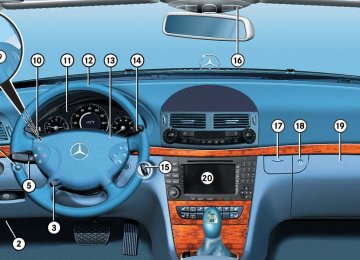
1 Outside temperature 2 Trip odometer 3 Automatic transmission program mode 4 Main odometer 5 Current gear selector lever position Above illustration shows the standard dis- play. For more information on menus displayed in the multifunction display, see “Menus” (컄 page 158).
155
Controls in detail Control system
Multifunction steering wheel
The displays in the multifunction display and the settings in the control system (컄 page 155) are controlled by the buttons on the multifunction steering wheel.
156
1 Multifunction display in the
5 Moving within a menu:
speedometer Operating the control system
2 Selecting the submenu or setting
Press button j for next display k for previous display
the volume: Press button æ up/to increase ç down/to decrease
3 Telephone*: Press button s to take a call to dial a call t to end a call
to reject an incoming call
4 Menu systems:
Press button è for next menu ÿ for previous menu
Pressing any of the buttons on the multi- function steering wheel will alter what is shown in the multifunction display. The information available in the multifunc- tion display is arranged in menus, each containing a number of functions or sub- menus. The individual functions are then found within the relevant menu (radio or CD op- erations under AUDIO, for example). These functions serve to call up relevant informa- tion or to customize the settings for your vehicle.
Controls in detail Control system
The menus are described on the following pages.
It is helpful to think of the menus, and the functions within each menu, as being ar- ranged in a circular pattern. 앫 If you press button è or ÿ re- peatedly, you will pass through each menu one after the other.
앫 If you press button k or j re- peatedly, you will pass through each function display, one after the other, in the current menu.
In the Settings menu, instead of functions you will find a number of submenus for calling up and changing settings. For in- structions on using these submenus, see the “Settings menu” section (컄 page 165). The number of menus available in the sys- tem depends on which optional equipment is installed in your vehicle.
157
Controls in detail Control system
Menus
This is what you will see when you scroll through the menus.
The table on the next page provides an overview of the individual menus.
158
Controls in detail Control system
Menu 3
NAV* (컄 page 163) Show route guidance instruc- tions, current direction trav- eledMenu 4
Distronic* (컄 page 163) Call up settingsMenus, submenus and functions
Menu 1
Standard display (컄 page 161) Digital speedometer Call up maintenance system dis- play Check tire inflation pressure* Check engine oil levelMenu 2
AUDIO (컄 page 161) Select radio station Operate CD player159
Controls in detail Control system
Menu 5
Vehicle status message memory1
(컄 page 164) Call up vehicle malfunction, warn- ing and system status messages stored in memoryMenu 6
SettingsMenu 7
Trip computerMenu 8
TEL*(컄 page 165) Reset to factory settings
(컄 page 180) Fuel consumption statistics after start
(컄 page 181) Load phone book
Instrument cluster submenu Fuel consumption statistics since
the last reset Call up range
Time/Date submenu Lighting submenu Vehicle submenu Convenience submenu Dynamic seat* submenu
Search for name in phone book
1 The vehicle status message memory menu is only displayed if there is a message stored.
The headings used in the menus table are designed to facilitate navigation within the system and are not neces- sarily identical to those shown in the control system displays.
The first function displayed in each menu will automatically show you which part of the system you are in.
160
Standard display menu
AUDIO menu
왘 Press button k or j repeatedly to select the functions in the standard display menu.
The following functions are available:
Function Calling up digital speedometer Calling up maintenance service indicator Checking tire inflation pressure* 335
Checking engine oil level 317Page 161
358Display digital speedometer 왘 Press button k or j repeatedly until the digital speedometer appears in the multifunction display.
The functions in the AUDIO menu operate the audio equipment which you currently have turned on. If no audio equipment is currently turned on, the message AUDIO off appears in the multifunction display. The following functions are available:
Function Select radio station Select satellite radio station* Operate CD player
Page 161
162
162Controls in detail Control system
Select radio station 왘 Turn on COMAND and select radio. Re- fer to separate COMAND operating in- structions.
왘 Press button è or ÿ repeatedly
until you see the currently tuned sta- tion in the multifunction display.
1 Waveband setting 2 Station frequency 왘 Press button k or j repeatedly
until the desired station is found.
You can only store new stations using the corresponding feature on the radio, see separate operating instructions. You can also operate the radio in the usual manner.
161
Controls in detail Control system
Select satellite radio station* (USA only) The satellite radio is treated as a radio ap- plication. 왘 Select SAT radio with the correspond-
ing softkey in the radio menu.
1 SAT mode and preset number 2 Setting for station selection using
memory
3 Channel name or number 왘 Press button k or j repeatedly
until the desired channel is found.
162
Additional optional satellite radio equipment and a subscription to satel- lite radio service provider are required for satellite radio operation. Contact an authorized Mercedes-Benz Center for details and availability for your vehicle. For more information, refer to separate COMAND operating instructions.
Operate the CD player 왘 Turn on COMAND and select CD. Refer
to separate COMAND operating in- structions.
왘 Press button è or ÿ repeatedly until the settings for the CD currently being played appear in the multifunc- tion display.
1 Current CD (for CD changer*) 2 Current track 왘 Press button k or j repeatedly
until the desired track is selected.
To select a CD from the magazine, press a number on the COMAND system key pad located in the center console.
NAV* menu
Distronic* menu
Use the Distronic menu to display the current settings for your Distronic system. What information is shown in the multi- function display depends on whether the Distronic system is active or inactive. Please refer to the “Driving systems” sec- tion of this manual (컄 page 243) for in- structions on how to activate Distronic. 왘 Press button è or ÿ repeatedly until you see one of the following two pictures in the multifunction display.
The NAV menu contains the functions needed to operate your navigation system. 왘 Press button è or ÿ repeatedly
until you see the message NAV in the multifunction display.
앫 If COMAND is switched off, the mes-
sage NAV off appears in the multifunc- tion display.
앫 With COMAND switched on but route guidance not activated, the direction of travel and, if available, the name of the street currently traveled on appear in the multifunction display.
앫 With COMAND switched on and route
guidance activated, the direction of travel and maneuver instructions ap- pear in the multifunction display.
Please refer to the COMAND manual for in- structions on how to activate the route guidance system.
Controls in detail Control system
Distronic deactivated When Distronic is deactivated, you will see the standard display in the multifunction display.
1 Vehicle ahead, if detected 2 Actual distance to vehicle ahead 3 Preset distance threshold to vehicle
ahead
4 Your vehicle 5 Symbol for activated distance warning
function
163
Controls in detail Control system
Distronic activated With Distronic activated, the Distronic display is shown in the multifunction dis- play and one or two segments around the set speed are illuminated in the speedometer.
1 Distronic activated
Vehicle status message memory menu
Use the vehicle status message memory menu to scan malfunction and warning messages that may be stored in the sys- tem. Such messages appear in the multi- function display and are based on conditions or system status the vehicle’s system has recorded. The vehicle status message memory menu only appears if there are any messages stored.
Warning!
Malfunction and warning messages are only indicated for certain systems and are inten- tionally not very detailed. The malfunction and warning messages are simply a remind- er with respect to the operation of certain systems and do not replace the owner’s and/or driver’s responsibility to maintain the vehicle’s operating safety by having all required maintenance and safety checks performed on the vehicle and by bringing the vehicle to an authorized Mercedes-Benz Center to address the malfunction and warning messages (컄 page 383).
왘 Press button è or ÿ repeatedly until the vehicle status message mem- ory appears in the multifunction dis- play. If the vehicle status message memory menu does not appear, then there are no messages stored.
164
Vehicle status messages have been recorded If conditions have occurred causing status messages to be recorded, the number of messages appears in the multifunction dis- play:
Should the vehicle’s system record any conditions while driving, the number of messages will reappear in the multifunc- tion display when the SmartKey in the starter switch is turned to position 0 or removed from the starter switch.
The vehicle status message memory will be cleared when you turn the SmartKey in the starter switch to position 1 or 2. You will then only see high-priority messages in the multi- function display (컄 page 383).
왘 Press button k or j.
The stored messages will now be dis- played in the order in which they have occurred. For malfunction and warning messages, see “Vehicle status messag- es in the multifunction display” (컄 page 383).
Controls in detail Control system
Settings menu
In the Settings menu there are two func- tions: 앫 The function To reset: Press reset button for 3 seconds, with which you can reset all the settings to the original factory settings.
앫 A collection of submenus with which you can make individual settings for your vehicle.
왘 Press button è or ÿ repeatedly until the Settings menu is seen in the multifunction display.
165
Submenus in the Settings menu 왘 Press button j.
In the multifunction display you see the collection of the submenus.
왘 Press button ç.
The selection marker moves to the next submenu.
The submenus are arranged by hierarchy. Scroll down with button ç, scroll up with button æ. With the selection marker on the desired submenu, use the button j to access the individual functions within that sub- menu. Once within the submenu, you can use the button j to move to the next function or the button k to move to the previous function within that submenu. The settings themselves are made with button æ or ç.
Controls in detail Control system
Resetting all settings You can reset all the functions of all sub- menus to the factory settings. 왘 Press the reset button in the instru-
ment cluster (컄 page 151) for approxi- mately 3 seconds. In the multifunction display you will see the request to press the reset button again to confirm.
왘 Press the reset button again.
The functions of all the submenus will reset to factory settings.
The settings you have changed will not be reset unless you confirm the action by pressing the reset button a second time. After approximately 5 seconds, the Settings menu reappears in the multifunction display. For safety reasons, the Lamp circuit headlamp function in the Lighting sub- menu is not reset while driving.
166
Controls in detail Control system
The table below shows what settings can be changed within the various menus. Detailed instructions on making individual settings can be found on the following pag- es.
INSTRUMENT CLUSTER TIME/DATE Select speedometer dis- play mode
Synchronizing the time
Select language
Set time (hours)
VEHICLE Set automatic lock- ing
LIGHTING Set daytime running lamp mode (USA only) Set locator lighting Limiting opening height of tailgate*
CONVENIENCE Activate easy-entry/exit feature Set parking position for exterior rear view mirror
DYNAMIC SEAT* Set level for dynamic seat, driver
Set level for dynamic seat, pas- senger
Select display (speed dis- play or outside tempera- ture) for status line Select display (speed dis- play or outside tempera- ture) for basic display
Set time (minutes) Setting ambient
lighting
Set date (month)
Setting headlamps delayed shut-off
Set date (day) Set date (year)
Setting interior lighting delayed shut-off
167
Controls in detail Control system
Instrument cluster submenu Access the Instr. cluster submenu via the Settings menu. Use the Instr. clus-