- Download PDF Manual
-
or others when contacted during braking, vehicle maneuvers, or in an accident. Keep in mind that objects placed in the cup holder may come loose during braking, vehicle maneuvers, or in an accident and be thrown around in the vehicle interior. Objects thrown around in the vehicle interior may cause an accident and/or serious personal injury.
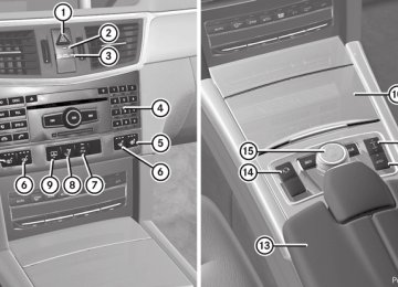
Cup holder in the center console
All vehicles except E 63 AMG X To open: slide cover = forwards until it
engages.
X To remove: slide catch ; forwards and
pull out cup holder :.
X To insert: insert cup holder : and slide
back catch ;.
X To close: press cover = briefly at the
front. Cover = moves back.
E 63 AMG X To open: slide cover : back.
Cup holder in the rear seat armrest ! Do not sit or lean your bodyweight on the armrests when they are folded out as you could damage them.
! Only fold the armrests up when the cup
holder is closed. The cup holder may otherwise be damaged.
BA 212 USA, CA Edition B 2011; 1; 5, en-US dimargi
2010-05-20T13:33:46+02:00 - Seite 289
Version: 3.0.3.6Features
289
X To open: raise the armrest cover. X Press release catch :.
Cup holder ; folds out forwards.
X Swing the armrest cover back down, if
necessary.
X To close: raise the armrest cover. X Swing cup holder ; back until it engages. X Swing the armrest cover back down, if
necessary.
Bottle holder G Warning! Do not transport heavy, sharp-edged, or fragile bottles in the bottle holder. In the event of an accident, the bottle holder cannot secure a bottle sufficiently. You and/ or vehicle occupants could be injured.
! Make sure that any bottles weighing more
than 0.5 kg that are stored in the bottle holder rest on the vehicle floor. The bottle holder could otherwise be damaged.
The bottle holder is designed for bottles with a capacity of 25 fl.oz (0.7 l) to 54 fl.oz (1.5 l). The bottle holder does not secure the bottles; it merely prevents them from tipping over.
X Press the outer edge of button : and slide in the direction of the arrow until the bottle fits into the opening.
X Insert the bottle into the bottle holder.
Sun visors G Warning Do not use the vanity mirror while driving. Keep the vanity mirrors in the sun visors closed while the vehicle is in motion. Reflected glare can endanger you and others.
: Mirror light ; Additional sun visor = Bracket ? Retaining clip, e.g. for a car park ticket A Vanity mirror B Mirror cover
BA 212 USA, CA Edition B 2011; 1; 5, en-US dimargi
2010-05-20T13:33:46+02:00 - Seite 290
Version: 3.0.3.6290 Features
Vanity mirror in the sun visor Mirror light : only functions if the sun visor is clipped into retainer ; and mirror cover A has been folded up.
Glare from the side
would damage the automatic roller mechanism.
! Do not drive the vehicle with the roller sunblind hooked in and the side windows opened simultaneously. The roller sunblind can jump out of the retainers and spring back suddenly when driving at high speeds, e.g. when driving on the freeway. This could damage the inertia reel. Therefore, either close the side window or retract the roller sunblind before driving at high speeds.
X Fold down sun visor :. X Pull sun visor : out of retainer =. X Swing sun visor : to the side. X Vehicles with an additional sun visor: slide sun visor : horizontally as desired.
X Fold down additional sun visor ;.
Roller sunblinds for the rear side windows
Rear window roller sunblind (Sedan) To extend/retract the roller sunblind G Warning When leaving the vehicle, always remove the SmartKey from the ignition lock. Always take the SmartKey with you and lock the vehicle. Do not leave children unattended in the vehicle, even if they are secured in a child restraint system, or with access to an unlocked vehicle. A child's unsupervised access to a vehicle could result in an accident and/or serious personal injury. The children could: Rinjure themselves on parts of the vehicle Rbe seriously or fatally injured through
excessive exposure to extreme heat or cold Rinjure themselves or cause an accident with
vehicle equipment that can be operated even if the SmartKey is removed from the ignition lock or removed from the vehicle, such as seat adjustment, steering wheel adjustment, or the memory function
X To extend: pull the roller sunblind out by tab : and hook it onto retainers ; at the top of the window.
! Always guide the roller sunblind by hand.
Do not let it snap back suddenly as this
If children open a door, they could injure other persons or get out of the vehicle and injure themselves or be injured by following traffic. Do not expose the child restraint system to direct sunlight. The child restraint system's metal parts, for example, could become very hot, and the child could be burned on these parts.
BA 212 USA, CA Edition B 2011; 1; 5, en-US dimargi
2010-05-20T13:33:46+02:00 - Seite 291
Version: 3.0.3.6Features
291
G Warning! When operating the rear window sunshade make sure there is no danger of anyone being harmed by the extending or retracting procedure. The extending or retracting procedure can be immediately halted by briefly pressing rear window sunshade switch. To reverse direction of movement, press rear window sunshade switch again.
! Make sure that the roller sunblind can
move freely. Otherwise, the roller sunblind or other objects could be damaged.
X To open: slide cover : forwards until it
engages.
X To remove the insert: hold insert = by the ribbing at the sides and lift it up and out ;.
X To refit the insert: press insert = into the
holder until it engages.
X To close: press cover : briefly at the
front. The cover moves back.
Ashtray in the rear compartment
X Turn the key to position 2 in the ignition
lock.
X To extend or retract: briefly press
button :. The roller sunblind fully extends or fully retracts.
Ashtray Ashtray in the cockpit i There is a stowage space under the
ashtray.
! The stowage space under the ashtray is
not heat resistant. Before placing lit cigarettes in the ashtray, make sure that the ashtray is properly engaged. Otherwise, the stowage space could be damaged.
X To open: briefly press cover ; at the top.
The ashtray opens.
X To remove the insert: press release button = and lift the insert up and out. X To re-insert the insert: replace insert :
from above.
X Press insert : into the holder until it
engages.
BA 212 USA, CA Edition B 2011; 1; 5, en-US dimargi
2010-05-20T13:33:46+02:00 - Seite 292
Version: 3.0.3.6292 Features
Cigarette lighter G Warning When leaving the vehicle, always remove the SmartKey from the ignition lock. Always take the SmartKey with you and lock the vehicle. Do not leave children unattended in the vehicle, even if they are secured in a child restraint system, or with access to an unlocked vehicle. A child's unsupervised access to a vehicle could result in an accident and/or serious personal injury. The children could: Rinjure themselves on parts of the vehicle Rbe seriously or fatally injured through
excessive exposure to extreme heat or cold Rinjure themselves or cause an accident with
vehicle equipment that can be operated even if the SmartKey is removed from the ignition lock or removed from the vehicle, such as seat adjustment, steering wheel adjustment, or the memory function
If children open a door, they could injure other persons or get out of the vehicle and injure themselves or be injured by following traffic. Do not expose the child restraint system to direct sunlight. The child restraint system's metal parts, for example, could become very hot, and the child could be burned on these parts. G Warning Never touch the heating element or sides of the lighter; they are extremely hot. Hold the knob only. Make sure any children traveling with you do not injure themselves or start a fire with the hot cigarette lighter.
Center console, front X Turn the key to position 2 in the ignition
lock.
X Slide cover : forwards until it engages. X Press in cigarette lighter ;.
Cigarette lighter ; will pop out automatically when the heating element is red-hot.
12 V sockets Points to observe before use ! If you are using all sockets in the vehicle,
make sure that you do not exceed the maximum current draw of 55 A. Otherwise, you will overload the fuses.
The socket can be used for accessories with a maximum power consumption of 180 W, e.g. lamps or chargers for mobile phones. If you use the socket for long periods when the engine is switched off, the battery may discharge.
BA 212 USA, CA Edition B 2011; 1; 5, en-US dimargi
2010-05-20T13:33:46+02:00 - Seite 293
Version: 3.0.3.6Dashboard socket
Socket in the rear compartment
Features
293
X Open the glove box (Y page 274). X Lift up the cover of socket :. An additional socket is installed in the center console on vehicles without an ashtray with cigarette lighter.
X Briefly press cover ; at the top.
The cover opens.
X Lift up the cover of socket :.
Socket in the trunk/cargo compartment
X To open: slide cover : forwards until it
engages.
X Lift up the cover of socket ;. X To close: press cover : briefly at the
front. The cover moves back.
Socket in the trunk (Sedan)
Socket in the cargo compartment (Wagon) X Lift up the cover of socket :.
BA 212 USA, CA Edition B 2011; 1; 5, en-US dimargi
2010-05-20T13:33:46+02:00 - Seite 294
Version: 3.0.3.6294 Features
115 V socket G Warning! The 115V AC socket operates at high voltage. Use the 115V AC socket in the vehicle with the same caution and prudence that you exercise when using power outlets at home. Keep any fluids away from the 115V AC socket. Do not clean the socket with fluids or tapered objects. Keep the 115V AC socket cover in the closed position, when not in use. Otherwise, you could suffer an electric shock and be seriously or even fatally injured. G Warning! A device that you connect must have a suitable plug that complies with U.S. standards. Never pull on the cable to unplug a plug from the 115V AC socket. Do not use a damaged connection cable. The 115V AC socket may not be connected to another 115V AC power source. Do not use converters to a grounding plug with the 115V AC socket. This could cause serious personal injury to you and/or others. G Warning! If the 115V AC socket is damaged or torn out of the trim, do not use or touch the 115V AC socket. Using a 115V AC socket that is damaged or torn out of the trim could cause serious personal injury to you and/or others.
The 115 V AC socket : provides an alternating voltage of 115 V, so that small electronic devices can be connected. These
devices, such as games consoles, chargers and laptops, together should not consume more than a maximum of 150 W. Requirements for this are: R12 V sockets in the footwell of the second
row of seats and in the stowage compartment must be functioning correctly (Y page 292).
Rthe plug of the electronic device is plugged
into the 115 V socket :.
Rthe on-board voltage is within the
permissible voltage range.
Rthe specified wattage of the electronic
device is equal to or less than the maximum permissible wattage (150 W) of 115 V socket :.
X Open flap =. X Insert the plug of the electronic device into
115 V socket :. Indicator lamp ; lights up.
If indicator lamp ; does not light up, please read the chapter on malfunctions. X To turn off: disconnect the plug from the
115 V socket :. Do not pull on the cable.
X Close flap =. Possible causes of malfunction: Rthe on-board voltage is not within the
permissible voltage range.
Rthe temperature of the DC/AC converter is
momentarily too high.
Rsome small electronic devices have a
constant power rating of less than 150 W but a very high switch-on current. These devices will not work. If you connect such a device, the 115 V socket : will not supply it with power.
If indicator lamp ; still does not light up, consult a specialist workshop, e.g. an authorized Mercedes-Benz Center.
BA 212 USA, CA Edition B 2011; 1; 5, en-US dimargi
2010-05-20T13:33:46+02:00 - Seite 295
Version: 3.0.3.6Features
295
mbrace26
Important safety notes ! A license agreement must exist in order to activate the mbrace service. Make sure that your system is activated and ready for use, and press the ï MB info call button to register. If you cannot carry out any of the steps mentioned, the system may not be activated. If you have any questions concerning activation, please contact one of the following service hotlines: RUSA: Response Center under866-990-9007
RCanada: Customer Service under
1-888-923-8367
Shortly after successfully registering with the mbrace service, a user ID and password will be sent to you by post. You can use this password to log in to the mbrace section under "Owners Online" at http:// www.mbusa.com27. The mbrace system is available if: Rit has been activated and is operational. Activation requires an available cellular phone network, a valid SIM card and a service subscription to a surveillance service provider.
Rthe battery is sufficiently charged. Rthe corresponding cellular phone network
is available for transmitting data to the customer center.
i Determining the location of the vehicle on a map is only possible if there is sufficient GPS reception and the vehicle position can be forwarded to the customer center.
26 The system is called TELEAID in Canada. 27 USA only. 28 USA only.
The mbrace system The mbrace system provides three different services: Rautomatic and manual emergency call RRoadside Assistance call RMB info call To control the volume during an mbrace call, proceed as follows: X Press the W or X button on the
multifunction steering wheel.
or X Use the volume controller of COMAND. You can find information and a description of all available features under "Owners Online" at http://www.mbusa.com28
System self-test After you have switched on the ignition, the system carries out a self-diagnosis. G Warning A malfunction in the system has been detected if any or all of the following conditions occur: RThe indicator lamp in the SOS button does
not come on during the system self-test.
RThe indicator lamp in Roadside Assistance button F does not come on during the system self-test.
RThe indicator lamp in Information button
ï does not come on during the system self-test.
RThe indicator lamp in the SOS button, Roadside Assistance button F, or Information button ï remains illuminated constantly in red after the system self-test. RThe message Tele Aid Inoperative or Tele Aid Not Activated appears in the
BA 212 USA, CA Edition B 2011; 1; 5, en-US dimargi
2010-05-20T13:33:46+02:00 - Seite 296
Version: 3.0.3.6296 Features
Once a connection has been established, the Call Connected message appears in the multifunction display. All important information on the emergency is compiled, for example: Rcurrent location of the vehicle (as
determined by the GPS system)
Rvehicle model Rvehicle color Rvehicle identification number A voice connection between the Response Center and the occupants of the vehicle will be established automatically soon after the emergency call has been initiated. If the vehicle occupants are able to respond, the Response Center will attempt to obtain more detailed information on the emergency. i If no vehicle occupant answers, an ambulance is immediately sent to the vehicle. G Warning If the indicator lamp in the SOS button is flashing continuously and there was no voice connection to the Response Center established, then the mbrace system could not initiate an emergency call (e.g. the relevant cellular phone network is not available). The message Call Failed appears in the multifunction display for approximately 10 seconds. Should this occur, assistance must be summoned by other means.
multifunction display after the system self- test.
If a malfunction is indicated as outlined above, the system may not operate as expected. In case of an emergency, help will have to be summoned by other means. Have the system checked at the nearest authorized Mercedes-Benz Center or contact the following service hotlines: RUSA: Response Center under the number
866-990-9007
RCanada: Customer Service under
1-888-923-8367.
Emergency call Important safety notes ! A license agreement must exist in order to activate the mbrace service. Make sure that your system is activated and ready for use, and press the ï MB info call button to register. If you cannot carry out any of the steps mentioned, the system may not be activated. If you have any questions concerning activation, please contact one of the following service hotlines: RUSA: Response Center under
866-990-9007
RCanada: Customer Service under
1-888-923-8367
An emergency call is dialed automatically if an air bag or Emergency Tensioning Device is triggered. i An automatically dialed mbrace
emergency call cannot be canceled. An emergency call can also be dialed manually. Once the emergency call is in progress, the indicator lamp in the SOS button flashes. The Connecting Call message appears in the multifunction display. COMAND is muted.
BA 212 USA, CA Edition B 2011; 1; 5, en-US dimargi
2010-05-20T13:33:46+02:00 - Seite 297
Version: 3.0.3.6Making an emergency call
Roadside Assistance call button
Features
297
X To initiate an emergency call
manually: press cover : briefly to open.
X Press SOS button ; briefly.
The indicator lamp in SOS button ; flashes until the emergency call is ended.
X Wait for the voice connection with the
Response Center.
X After the emergency call is ended, close
cover :. G Warning If you feel at any way in jeopardy when in the vehicle (e.g. smoke or fire in the vehicle, vehicle in a dangerous road location), please do not wait for voice contact after you have pressed the SOS button. Carefully leave the vehicle and move to a safe location. The Response Center will automatically contact local emergency officials with the vehicle's approximate location if they receive an automatic SOS signal and cannot make voice contact with the vehicle occupants.
X Press and hold Roadside Assistance
button : for more than two seconds. A call to a Mercedes-Benz Roadside Assistance Representative is initiated. The indicator lamp in Roadside Assistance button : flashes while the call is active. The Connecting Call message appears in the multifunction display and the audio system or COMAND is muted. If a connection can be established, the Call Connected message appears in the multifunction display. If a mobile phone network is available and there is sufficient GPS reception, the mbrace system transmits data to the Response Center, for example: Rcurrent location of the vehicle Rvehicle identification number Rvehicle model Rvehicle color i The COMAND display shows that an
mbrace call is active. You can switch to the navigation menu by pressing the NAVI button on COMAND during the call. Spoken commands are not available.
A voice connection is established between the Mercedes-Benz Roadside Assistance Representative and the vehicle occupants. X Describe the type of assistance needed. The Mercedes-Benz Roadside Assistance Representative either sends a qualified Mercedes-Benz technician or organizes for
BA 212 USA, CA Edition B 2011; 1; 5, en-US dimargi
2010-05-20T13:33:46+02:00 - Seite 298
Version: 3.0.3.6298 Features
established. The Connecting Call message appears in the multifunction display and COMAND is muted. If a connection can be established, the Call Connected message appears in the multifunction display. If a mobile phone network is available and there is sufficient GPS reception, the mbrace system transmits data to the Response Center, for example: Rcurrent location of the vehicle Rvehicle identification number Rvehicle model Rvehicle color i The COMAND display shows that an
mbrace call is active. You can switch to the navigation menu by pressing the NAVI button on COMAND during the call. Spoken commands are not available.
A voice connection between the Response Center and the vehicle occupants is established. You can obtain information on how to operate your vehicle's systems, on the location of the nearest authorized Mercedes- Benz Center, and on further products and services offered by Mercedes-Benz USA. Further details on the mbrace system can be found under http://www.mbusa.com30. Log in under "Owners Online". i If the indicator lamp in MB info call
button : flashes continuously and no voice connection to the Response Center has been established, then the mbrace system has failed to initiate an MB info call (e.g. the corresponding mobile phone network is not available). The Call Failed message appears in the multifunction display.
your vehicle to be transported to the nearest authorized Mercedes-Benz Center. You may be charged for services such as repair work and/or towing. Further details are available in your mbrace manual. i If the indicator lamp in MB info call
button : flashes continuously and it was not possible to establish a voice connection to the Response Center, then the mbrace system has failed to initiate a Roadside Assistance call (e.g. the corresponding cellular phone network is not available). The Call Failed message appears in the multifunction display.
X To end a call: press the ~ button on the
multifunction steering wheel.
or X Press the corresponding button for ending
a phone call on COMAND.
i Sign and Drive services29: you are not
charged for services such as jump-starting, providing a few gallons of fuel for a fuel tank that has been run dry or changing a flat tire with the vehicle's own spare tire.
MB Info call button
X Press and hold MB info call button : for
more than two seconds. A call to the Response Center is initiated. MB info call button indicator lamp : flashes while the connection is being
29 USA only. 30 USA only.
BA 212 USA, CA Edition B 2011; 1; 5, en-US dimargi
2010-05-20T13:33:46+02:00 - Seite 299
Version: 3.0.3.6X To end a call: press the ~ button on the
multifunction steering wheel.
or X Press the corresponding button for ending
a phone call on COMAND.
Call priority An emergency call can still be initiated even if a service call is currently active, e.g. a Roadside Assistance call or an MB info call. In this case, an emergency call will take priority and override all other active calls. The indicator lamp of the respective button flashes until the call is ended. An emergency call can only be terminated by the Response Center. All other calls can be ended by pressing the ~ button on the multifunction steering wheel or the corresponding button for ending a telephone call on COMAND. i When an mbrace call has been initiated, COMAND is muted. The mobile phone is no longer connected to COMAND. If you must use your mobile phone, we recommend that you do this only when the vehicle is stationary and in a safe location.
Downloading destinations in COMAND Destination Download gives you access to a database with over 10 million points of interest (POIs) which can be downloaded to the navigation system of your vehicle. If you know the destination, you can download the address or obtain the location of points of interest (POIs) or important destinations in the surrounding area. You are prompted to confirm route guidance to the entered address. The system calculates the route and subsequently starts the route guidance with the address entered.
31 USA only.
Features i If you select No, the address can be stored in the address book.
299
i The Destination Download function is available if the corresponding cellular phone network is available and data transfer is possible.
Search & Send "Search & Send" is a destination entry service. You can find further information on "Search & Send" in the separate COMAND operating instructions.
Vehicle remote opening If you have unintentionally locked your vehicle (e.g. the SmartKey is inside the vehicle) and a replacement key is not available: X Contact the following service hotlines:
RUSA: Response Center under the
number 866-990-9007
RCanada: Customer Service under
1-888-923-8367
You will be asked for your password.
X Return to your vehicle at the time arranged
with the Response Center.
X Pull the trunk handle/tailgate handle for at least 20 seconds until the indicator lamp in the SOS button (Y page 296)flashes. The Connecting Call message appears in the multifunction display.
Alternatively, the vehicle can also be opened via the Internet in the "Owners Online" section using your ID number and password31. i Vehicle remote unlocking is only possible
if the corresponding cellular phone network is accessible. The SOS button flashes and the Connecting Call message appears in the multifunction display to confirm that the
BA 212 USA, CA Edition B 2011; 1; 5, en-US dimargi
2010-05-20T13:33:46+02:00 - Seite 300
Version: 3.0.3.6300 Features
command for vehicle remote unlocking has been received. If you pull the trunk handle for more than 20 seconds before receiving authorization for remote unlocking, you must wait 15
minutes before you can pull on the handle of the trunk lid again.Vehicle remote closing in an emergency If you forget to lock your vehicle but are no longer in the vicinity of the vehicle, it can be locked for you by the Response Center. The vehicle can be locked remotely up to four days after the ignition was last switched off. X Contact the following service hotlines:
RUSA: Response Center under
866-990-9007
RCanada: Customer Service under
1-888-923-8367
You will be asked for your PIN. The next time you are in your vehicle and switch on the ignition, the Tele Aid Doors locked by remote control message appears in the multifunction display. i The vehicle remote locking feature is
available when the relevant mobile phone network is available and data connection is possible.
Stolen Vehicle Recovery Services If your vehicle has been stolen: X Contact the police.
The police will issue an incident report. This report has a number.
X This number will be forwarded to the
Response Center together with your PIN. The Response Center will then attempt to covertly contact the mbrace system. The Response Center contacts you and the local law enforcement authority if the vehicle is located. However, only the law enforcement authority is informed of the location of the vehicle.
i If the anti-theft alarm system remains activated for longer than thirty seconds, mbrace is automatically connected to the Customer Assistance Center.
Garage door opener Important safety notes Up to three different door and gate systems can be operated using the remote control integrated in the overhead control panel. i Certain garage door openers are not compatible with the integrated remote control. If you experience difficulties with the programming of the integrated remote control, contact an authorized Mercedes- Benz Center or call the following telephone assistance service: RUSA: Mercedes-Benz Customer
Assistance Center on 1-800-FOR-MERCedes
RCanada: Customer Service
on1-800-387-0100
G Warning Before programming the integrated remote control to a garage door opener or gate operator, make sure people and objects are out of the way of the device to prevent potential harm or damage. When programming a garage door opener, the door moves up or down. When programming a gate operator, the gate opens or closes. Do not use the integrated remote control with any garage door opener that lacks safety stop and reverse features as required by U.S. federal safety standards (this includes any garage door opener model manufactured before April 1, 1982). A garage door that cannot detect an object - signaling the door to stop and reverse - does not meet current U.S. federal safety standards. When programming a garage door opener, park vehicle outside the garage.
BA 212 USA, CA Edition B 2011; 1; 5, en-US dimargi
2010-05-20T13:33:46+02:00 - Seite 301
Version: 3.0.3.6Features
301
Do not run the engine while programming the integrated remote control. Inhalation of exhaust gas is hazardous to your health. All exhaust gas contains carbon monoxide (CO), and inhaling it can cause unconsciousness and possible death. All exhaust gas contains carbon monoxide (CO), and inhaling it can cause unconsciousness and possible death.
i USA only:
This device complies with part 15 of the FCC rules. Operation is subject to the following two conditions: 1. The device must not cause harmful interference. 2. The device must withstand any interference received, including interference that may cause undesired operation. Unauthorized modification of this device could void the device's operating permit.
i Canada only:
This device complies with the RSS-210
requirements of Industry Canada. Operation is subject to the following two conditions: 1. The device must not cause harmful interference. 2. The device must accept any interference received, including interference that may cause undesired operation. Unauthorized modification of this device could void the user's authority to legally operate the device.Programming the remote control Programming G Warning! Only press the transmitter button on the integrated remote control if there are no persons or objects present within the sweep of the garage door. People could otherwise be injured by the movement of the door.
Remote control in the rear-view mirror Garage door remote control A is not part of the garage door opener. i To achieve the best result, insert new batteries in garage door remote control A of your garage door drive before programming.
X Erase the memory of the integrated remote control (Y page 303) before programming it for the first time.
X Turn the SmartKey to position 2 in the
ignition lock.
X Press and hold one of transmitter
buttons ; to ? on the integrated remote control. After a short time, indicator lamp : will start flashing. It flashes about once per second.
i Indicator lamp : flashes immediately
the first time that the transmitter button is programmed. If this transmitter button has already been programmed, indicator lamp : will only start flashing at a rate of once per second after 20 seconds have elapsed.
X Keep the transmitter button depressed. X Point transmitter button B of garage door remote control A towards the transmitter buttons on the rear-view mirror from a distance of 2 to 12 inches (5 to 20 cm).
i The distance between garage door remote control A and the integrated garage door opener depends on the system of the garage door drive. You might require
BA 212 USA, CA Edition B 2011; 1; 5, en-US dimargi
2010-05-20T13:33:46+02:00 - Seite 302
Version: 3.0.3.6302 Features
several attempts. You should test every position for at least 20 seconds before trying another position.
X Keep transmitter button B on garage door remote control A pressed until indicator lamp : starts to flash rapidly. The programming has been successful if indicator lamp : flashes rapidly.
X Release transmitter buttons ;, = or ?
on the integrated remote control or transmitter button on the garage door remote control B.
If indicator lamp : goes out after approximately 20 seconds and has not flashed rapidly: X Release transmitter buttons ;, = or ?
on the integrated remote control or transmitter button on the garage door remote control B.
X Repeat the procedure for the other
transmitter buttons. When doing so, vary the distance between the garage door's remote control and the transmitter buttons in the rear-view mirror.
i If the garage door system works with a
rolling code, you must synchronize the remote control integrated into the rear- view mirror with the garage door system receiver after programming. You will find further information in the garage door opening system's operating instructions, e.g. the sections on "Synchronizing the transmitter" or "Registering a new transmitter". You can also call the hotline mentioned above.
Notes on programming the remote control Canadian radio frequency laws require transmitter signals to "time-out" (or quit) after several seconds of transmission. This may not be long enough for the integrated signal transmitter to pick up the signal during programming. Similar to this Canadian law,
some U.S. gate operators are designed to "time-out" in the same manner. If you live in Canada or have difficulties programming the garage door opener (regardless of where you live) when using the programming steps (see above), proceed as follows: X Press transmitter button (;, = or ?) and hold it down during the following steps until the setup has been completed successfully.
X At the same time, press transmitter button B of the garage door remote control for two seconds, then release it for two seconds, then press it again for two seconds.
X Repeat this sequence on transmitter button B of the garage door remote control until the frequency signal has been learned.
X If the setup procedure is successful,
indicator lamp : flashes once slowly and goes out after a few seconds.
X Continue with the other programming
steps (see above).
Problems when programming If you have problems when programming the integrated remote control, please note the following: Rcheck the transmitter frequency of garage door remote control A (which can usually be found on the rear of the remote control). The integrated remote control is compatible with equipment that operates in the frequency range 280 to 390 MHz.
Rreplace the batteries in garage door remote control A. This increases the likelihood of garage door remote control A sending a strong and precise signal to the integrated remote control on the rear-view mirror.
RWhen aiming the garage door remote
control at the transmitter buttons on the rear-view mirror, hold garage door remote control A at differing distances and angles
BA 212 USA, CA Edition B 2011; 1; 5, en-US dimargi
2010-05-20T13:33:46+02:00 - Seite 303
Version: 3.0.3.6Features
303
from the transmitter button that you are programming. Try different angles from a distance of 2 to 12 inches (5 to 30 cm) or the same angle from differing distances.
RIf there is another garage door remote
control for the same device, perform the programming steps again using the remote control. Before performing these steps, make sure that new batteries have been installed in the garage door remote control. RAlign the antenna cable of the garage door
opener unit. This can improve signal reception/transmission.
Opening or closing the garage door Once programmed, the integrated remote control will assume the function of the garage door system's remote control. Please also read the operating instructions for the garage door system. X Turn the SmartKey to position 2 in the
ignition lock.
X Press transmitter button ;, = or ? in the
overhead control panel that you have programmed to operate the garage door. Garage door system with fixed code: indicator lamp : lights up continuously. Garage door system with rolling code: indicator lamp : flashes briefly and then lights up for approximately two seconds. This is repeated for up to 20 seconds.
i The transmitter will transmit a signal for as long as the transmitter button is being pressed. The transmission will be halted after a maximum of 20 seconds and indicator lamp : will flash. Press the transmitter button again, if necessary.
Clearing the remote control memory X Turn the SmartKey to position 2 in the
ignition lock.
X Press and hold transmitter buttons ;
and ? for approximately 20 seconds until indicator lamp : flashes rapidly. The memory is cleared.
i You should clear the remote control
memory before selling the vehicle.
Compass
To obtain correct direction display in rear- view mirror :, the compass must be calibrated and the magnetic field zone set. X To call up the compass: briefly press
button =. The compass indicates the direction in which the vehicle is currently driving: N, NE, E, SE, S, SW, W or NW. X To calibrate the compass: determine
your position using the following the zone maps.
BA 212 USA, CA Edition B 2011; 1; 5, en-US dimargi
2010-05-20T13:33:46+02:00 - Seite 304
Version: 3.0.3.6304 Features
a circle without impeding the remaining traffic.
In order to calibrate the compass correctly, observe the following points: Rcalibrate the compass in the open and not
in the vicinity of steel structures or high- voltage power lines
Rswitch off electrical consumers such as
climate control, the windscreen wipers or the rear window heating
Rclose all doors and the trunk lid/tailgate X Switch on the ignition. X Press and hold button = for approximately six seconds until the C symbol appears in compass display ;.
X Drive a full circle at approximately 3 mph
(5 km/h) to 6 mph (10 km/h). Once the calibration has been successfully completed, the current heading appears in compass display ;.
Floormat on the driver's side G Warning! Whenever you are using a floormat, make sure there is enough clearance and that the floormat is securely fastened. The floormat should always be securely fastened using the fastening equipment. Before driving off, check that the floormat is securely in place and adjust it if necessary. A loose floormat could slip and hinder proper functioning of the pedals. Do not place several floormats on top of each other as this may impair pedal movement.
Zone map for North America
Zone map for South America X Press and hold button = for approximately
three seconds. The currently selected zone appears in compass display ;.
X To select the zone: press button = repeatedly until the desired zone is selected. The zone has been selected when compass display ; shows the point of the compass. This takes a few seconds.
X To calibrate the compass: make sure that there is sufficient space for you to drive in
BA 212 USA, CA Edition B 2011; 1; 5, en-US dimargi
2010-05-20T13:33:46+02:00 - Seite 305
Version: 3.0.3.6Features
305
X Slide seat backwards. X To install: place the floormat in position. X Press floormat eyelets : onto retainer
pins ;.
X To remove: pull the floormats off
retainers ;.
X Remove the floormat.
BA 212 USA, CA Edition B 2011; 1; 5, en-US dimargi
2010-05-20T13:33:46+02:00 - Seite 306
Version: 3.0.3.6306
BA 212 USA, CA Edition B 2011; 1; 5, en-US dimargi
2010-05-20T13:33:46+02:00 - Seite 307
Version: 3.0.3.6Vehicle equipment ............................ 308
Engine compartment ........................ 308
Service ............................................... 313
Care .................................................... 313307
BA 212 USA, CA Edition B 2011; 1; 5, en-US dimargi
2010-05-20T13:33:46+02:00 - Seite 308
Version: 3.0.3.6308 Engine compartment
Vehicle equipment
i This manual describes all the standard and optional equipment of your vehicle which was available at the time of purchase. Country-specific differences are possible. Bear in mind that your vehicle may not feature all functions described here. This also refers to safety-related systems and functions.
Engine compartment Hood Opening the hood G Warning Do not pull the release lever while the vehicle is in motion. Otherwise, the hood could be forced open by passing air flow. This could cause the hood to come loose and injure you and/or others. G Warning Do not open the hood when the engine is overheated. You could be seriously injured. Observe the coolant temperature gauge to determine whether the engine may be overheated. If you see flames or smoke coming from the engine compartment, move away from the vehicle. Wait until the engine has cooled. If necessary, call the fire department. G Warning There is a risk of injury if the hood is open, even if the engine is not running. Some engine components can become very hot. To avoid the risk of burns, only touch those components described in the Operator's Manual and observe the relevant safety notes.
G Warning To help prevent personal injury, stay clear of moving parts when the hood is open and the engine is running. The radiator fan may continue to run for approximately 30 seconds or may even restart after the engine has been turned off. Stay clear of fan blades. G Warning! Vehicles with gasoline engine: The engine is equipped with a transistorized ignition system. Because of the high voltage it is dangerous to touch any components (ignition coils, spark plug sockets, diagnostic socket) of the ignition system Rwith the engine running Rwhile starting the engine Rwhen the ignition is switched on and the
engine is turned manually G Warning! Vehicles with diesel engine: The engine is equipped with a high-voltage electronic control unit for the injection system. Because of the high voltage it is dangerous to touch any components of the injection system (injectors, electrical wires) Rwith the engine running Rwhile starting the engine Rwhen the ignition is switched on
X Make sure that the windshield wipers are
switched off. G Warning The windshield wipers and wiper linkage could be set in motion. When the hood is open, you or others could be injured by the wiper linkage. Make sure that the windshield wipers are switched off. Remove the SmartKey or make sure that no ignition position has been selected with KEYLESS-GO. All indicator lamps must be off in the instrument cluster.
BA 212 USA, CA Edition B 2011; 1; 5, en-US dimargi
2010-05-20T13:33:46+02:00 - Seite 309
Version: 3.0.3.6Engine compartment
309
X Lower the hood and let it fall from a height
of approximately 8 inches (20 cm).
X Check that the hood has engaged properly. If the hood can be raised slightly, it is not properly engaged. Open it again and close it with a little more force.
Radiator i Vehicles with a diesel engine: do not
cover the radiator, for example with a winter front or bug cover. Otherwise, the readings of the on-board-diagnostic system may be inaccurate. Some of these readings are required by law and must be accurate at all times.
Engine oil Notes on the oil level Depending on the driving style, the vehicle consumes up to 0.9 US qt (0.8 l) of oil over a distance of 600 miles (1000 km). The oil consumption may be higher than this when the vehicle is new or if you frequently drive at high engine speeds. When checking the oil level: Rpark the vehicle on a level surface. Rthe engine should be switched off for at
least five minutes if the engine is at normal operating temperature.
Rthe engine should be switched off for at
least 30 minutes if it is not at normal operating temperature (i.e. if you only start the engine briefly).
Checking the oil level using the oil dipstick Depending on the engine, the oil dipstick may be installed in a different location.
X Pull release lever : on the hood.
The hood is released.
! Make sure that the windshield wipers are not folded away from the windshield. You could otherwise damage the windshield wipers or the hood.
X Reach into the gap, pull hood catch
handle ; up and lift the hood.
Closing the hood G Warning When closing the hood, use extreme caution not to catch hands or fingers. Be careful that you do not close the hood on anyone. Make sure the hood is securely engaged before driving off. Do not continue driving if the hood can no longer engage after an accident, for example. The hood could otherwise come loose while the vehicle is in motion and injure you and/or others.
BA 212 USA, CA Edition B 2011; 1; 5, en-US dimargi
2010-05-20T13:33:46+02:00 - Seite 310
Version: 3.0.3.6310 Engine compartment
found on the Internet at http:// www.mbusa.com (USA only). Further information on tested and approved engine oils and oil filters can be obtained from any authorized Mercedes-Benz Center. The following causes engine failure or damage to the exhaust system: Rusing engine oils and oil filters that are not specifically approved for the service system
Rreplacing the engine oil and oil filter later than the specified replacement interval required by the service system
Rusing engine oil additives
Example: engine oil cap
Engine oil cap (AMG vehicles) X Turn cap : counter-clockwise and remove
it.
X Add the amount of oil required. Fill carefully to the maximum mark on the oil dipstick. i The difference in quantity between the
MIN mark and the MAX mark on the
Example: vehicles with a gasoline engine
Example: vehicles with a diesel engine X Pull oil dipstick : out of the dipstick guide
tube.
X Wipe off oil dipstick :. X Slowly insert oil dipstick : into the
dipstick guide tube to the stop, and take it out again. The oil level is correct if the level is between MIN mark = and MAX mark ;.
X Add oil if necessary.
Adding engine oil H Environmental note When adding oil, take care not to spill any. If oil enters the soil or waterways, it is harmful to the environment.
! Only use engine oils and oil filters which
have been approved for vehicles with a service system. A list of the engine oils and oil filters that have been tested and approved according to the Mercedes-Benz specifications for service products can be
BA 212 USA, CA Edition B 2011; 1; 5, en-US dimargi
2010-05-20T13:33:46+02:00 - Seite 311
Version: 3.0.3.6dipstick is (depending on the engine) approximately 1.6 to 2.1 US qt. (1.5 to 2 l). ! Do not add too much oil. If the oil level is above the MAX mark on the dipstick, too much oil has been added. This can lead to damage to the engine or the catalytic converter. Have excess oil siphoned off.
Further information on engine oil (Y page 391). X Replace cap : on the filler neck and
tighten clockwise. Ensure that the cap locks into place securely.
Checking and adding other service products Checking the coolant level Only check the coolant level when the vehicle is on a level surface and the engine has cooled down. X Turn the SmartKey to position
2(Y page 149) in the ignition lock. On vehicles with KEYLESS-GO, press the Start/Stop button twice (Y page 150).
X Check the coolant temperature display in
the instrument cluster. The coolant temperature must be below 158 ‡ (70 †). G Warning In order to avoid any potentially serious burns: Ruse extreme caution when opening the hood if there are any signs of steam or coolant leaking from the cooling system, or if the coolant temperature display indicates that the coolant is overheated.
Rdo not remove the pressure cap on the
coolant reservoir if the coolant temperature is above 158 ‡ (70 †). Allow the engine to cool down before removing the cap. The coolant reservoir contains hot fluid and is under pressure.
Engine compartment
311
Rusing a rag, slowly turn the cap
approximately 1/2 turn to relieve excess pressure. If opened immediately, scalding hot fluid and steam will be blown out under pressure.
Rdo not spill antifreeze on hot engine parts. Antifreeze contains ethylene glycol which may burn if it comes into contact with hot engine parts.