- 2012 Mercedes-Benz CL Class Owners Manuals
- Mercedes-Benz CL Class Owners Manuals
- 2008 Mercedes-Benz CL Class Owners Manuals
- Mercedes-Benz CL Class Owners Manuals
- 2011 Mercedes-Benz CL Class Owners Manuals
- Mercedes-Benz CL Class Owners Manuals
- 2007 Mercedes-Benz CL Class Owners Manuals
- Mercedes-Benz CL Class Owners Manuals
- 2002 Mercedes-Benz CL Class Owners Manuals
- Mercedes-Benz CL Class Owners Manuals
- 2013 Mercedes-Benz CL Class Owners Manuals
- Mercedes-Benz CL Class Owners Manuals
- 2004 Mercedes-Benz CL Class Owners Manuals
- Mercedes-Benz CL Class Owners Manuals
- 2000 Mercedes-Benz CL Class Owners Manuals
- Mercedes-Benz CL Class Owners Manuals
- 2010 Mercedes-Benz CL Class Owners Manuals
- Mercedes-Benz CL Class Owners Manuals
- 2006 Mercedes-Benz CL Class Owners Manuals
- Mercedes-Benz CL Class Owners Manuals
- 2003 Mercedes-Benz CL Class Owners Manuals
- Mercedes-Benz CL Class Owners Manuals
- 2005 Mercedes-Benz CL Class Owners Manuals
- Mercedes-Benz CL Class Owners Manuals
- 2009 Mercedes-Benz CL Class Owners Manuals
- Mercedes-Benz CL Class Owners Manuals
- 2001 Mercedes-Benz CL Class Owners Manuals
- Mercedes-Benz CL Class Owners Manuals
- Download PDF Manual
-
switch off the engine. Otherwise, parts of the individuals body could be trapped.
! When you switch off the engine, the entire vehicle is lowered. When parking, position your vehicle in such a way that it will not scrape against a curb, for example, when it is lowered. Your vehicle could otherwise be damaged.
Controls in detail Driving systems
i CL 63 AMG and CL 65 AMG only: When you switch off the engine, the entire vehi- cle is lowered by 0.2 in (5 mm).
Vehicle level control
Warning!
To help avoid personal injury, keep hands and feet away from wheel housing area, and stay away from under the vehicle when lowering the vehicle chassis.
461
Controls in detail Driving systems
Your vehicle automatically adjusts its ride height to: 앫 increase vehicle safety 앫 reduce fuel consumption The vehicle chassis ride height is raised or lowered according to the selected level setting and to the vehicle speed: 앫 With increasing speed, ride height is re-
duced by up to approximately 0.4 in (10 mm).
앫 With decreasing speed, the ride height is again raised to the selected vehicle level.
i These height adjustments are so small that you may not notice any change.
The following vehicle level settings can be selected when the vehicle is stationary:
Level Normal
Raised
For driving on normal roads. The indicator lamp is off. For driving on rough roads or with snow chains. The indica- tor lamp is on.
Select the “Raised” level setting only when required by current driving conditions. Otherwise: 앫 Fuel consumption may increase. 앫 Handling may be impaired.
i The selected vehicle level setting remains stored in memory even if the engine is turned off and restarted.
462
1 Vehicle level control switch 2 Indicator lamp
Selecting a higher level 왘 Start the engine. If indicator lamp 2 is off: 왘 Press switch 1.
Indicator lamp 2 comes on. The vehi- cle is raised to a higher level.
Selecting a normal level 왘 Start the engine. If indicator lamp 2 is on: 왘 Press switch 1.
Indicator lamp 2 goes out. The vehicle is adjusted to a normal level.
Suspension tuning The suspension tuning is set according to: 앫 your driving style 앫 road surface conditions 앫 the vehicle loading 앫 your choice of suspension style
The program mode selector switch (C/S) (컄 page 427) is used to adjust the suspen- sion tuning:
Driving program Suspension tuning C Comfort
comfortable (default setting) sporty for dynamic driving
S Sport
왘 Start the engine. 왘 Select the desired driving program.
Controls in detail Driving systems
Parktronic system*
Warning!
Parktronic is a supplemental system. It is not intended to, nor does it replace, the need for extreme care. The responsibility during parking and other critical maneuvers always remains with the driver.
Warning!
Make sure no persons or animals are in the area in which you are maneuvering. You could otherwise injure them.
! Special attention must be paid to objects with smooth surfaces or low silhouettes (e.g. trailer couplings, painted posts, elevated cross- bars or road curbs). Such objects may not be detected by the system and can damage the vehicle.
463
Controls in detail Driving systems
! The operational function of the Parktronic system can be affected by dirty sensors, espe- cially at times of snow and ice. Make sure that the area on the bumpers around the sensors is free of dirt, ice and/or slush, otherwise the Parktronic system may not function properly, see “Cleaning the Parktronic* system sensors” (컄 page 600).
i Interference caused by other ultrasonic sig- nals (e.g. working jackhammers, car wash, or the air brakes of trucks) can cause the system to send erratic indications, and should be taken into consideration.
The Parktronic system is an electronic parking aid with ultrasonic sensors that helps you while parking. It visually and audibly indicates the relative distance between the vehicle and an ob- stacle. The Parktronic system is automatically ac- tivated when you switch on the ignition, re- lease the electronic parking brake or start the engine and engage drive position D, re- verse gear R or neutral position N.
464
i To function properly, the sensors must be free of dirt, ice, snow and slush. Clean the sen- sors regularly, being careful not to scratch or damage the sensors, see “Cleaning the Park- tronic* system sensors” (컄 page 600).
Range of the sensors
The Parktronic system deactivates at speeds over approximately 11 mph (18 km/h). At lower speeds the Parktronic system turns on again. The Parktronic system also deactivates when you set the automatic transmission to park position P or secure the vehicle in place with the electronic parking brake and switch off the engine. The Parktronic system monitors the sur- roundings of your vehicle with six sensors in the front bumper and four sensors in the rear bumper.
1 Sensors in the front bumper (Only visi-
ble without DISTRONIC Plus*)
Front sensors
Minimum distance
Center Corners
approx. 40 in (100 cm) approx. 24 in (60 cm)
Center Corners
approx. 8 in (20 cm) approx. 6 in (15 cm)
If the system detects an obstacle in this range, all the distance warning segments illuminate and you hear a warning signal. If the obstacle is closer than the minimum distance, the actual distance may no long- er be indicated by the system.
Rear sensors
Center Corners
approx. 48 in (120 cm) approx. 32 in (80 cm)
! During parking maneuvers, pay special at- tention to objects located above or below the height of the sensors (e.g. street curbs, painted posts, or trailer hitches etc.). The Parktronic sys- tem will not detect such objects at close range and damage to your vehicle or the object may result. Ultrasonic signals from outside sources (e.g. truck air brakes, car wash, or jackhammers) may impair the operation of the Parktronic system.
Controls in detail Driving systems
Warning indicators Visual signals indicate to the driver the rel- ative distance between the sensors and an obstacle. The warning indicator for the front area is in the instrument cluster. The warning indi- cator for the rear area is on the roof liner in the rear.
1 Left side of the vehicle 2 Right side of the vehicle 3 Readiness indicators Each warning indicator is divided into five yellow and two red distance segments for either side of the vehicle. If yellow readiness indicators 3 under the distance segments are lit, Parktronic is ready to measure.
465
Controls in detail Driving systems
The position of the gear selector lever de- termines which warning indicators will be activated.
Gear selector lever position
Warning indicator
Front area activated Front and rear area activated With the electronic parking brake engaged: neither activated. With the electronic parking brake released: front and rear area activated. Neither activated
As your vehicle approaches an object, one or more distance segments will illuminate, depending on the distance. When the sev- enth distance segment illuminates, you have reached the minimum distance.
466
앫 Front area:
An intermittent acoustic warning will sound as the first red distance segment illuminates and a constant acoustic warning lasting a maximum of 2 seconds will sound for the second red distance segment. The signal is canceled when the gear selector lever is placed in park position P.
앫 Rear area:
An intermittent acoustic warning will sound as the first red distance segment illuminates and a constant acoustic warning lasting a maximum of 2 seconds will sound for the second red distance segment. The signal is canceled when the gear selector lever is placed in drive position D or park position P.
Switching on or off Parktronic system The Parktronic system can be switched off manually.
1 Parktronic button 2 Indicator lamp
왘 Switching off the Parktronic sys-
왘 Have the Parktronic system checked
Park Assist*
Controls in detail Driving systems
tem: Press button 1. Indicator lamp 2 comes on.
왘 Switching on the Parktronic system:
Press button 1 again. Indicator lamp 2 goes out.
i The Parktronic system is automatically switched on when the ignition is switched on (컄 page 365).
Parktronic system malfunction If only the red distance segments illumi- nate and an acoustic warning sounds, there is a malfunction in the Parktronic system. The Parktronic system will auto- matically switch off after 20 seconds and the indicator lamp in the Parktronic switch comes on.
by an authorized Mercedes-Benz Center as soon as possible.
If only the red distance segments illumi- nate and no acoustic warning sounds, the Parktronic system sensors are dirty or there is an interference from other radio or ultrasonic signals. The Parktronic system will automatically switch off after 20 sec- onds and the indicator lamp in the Parktronic switch comes on. 왘 Switch off the ignition (컄 page 365). 왘 Clean the Parktronic system sensors
(컄 page 600).
왘 Switch on the ignition. or 왘 Check the Parktronic system operation at another location to rule out interfer- ence from outside radio or ultrasonic signals.
Warning!
Park Assist is a supplemental system. It is not intended to, nor does it replace, the need for extreme care. The responsibility during parking and other critical maneuvers always remains with the driver.
Warning!
Make sure no persons or animals are in the area in which you are maneuvering. You could otherwise injure them.
! Special attention must be paid to objects with smooth surfaces or low silhouettes (e.g. trailer couplings, painted posts, elevated cross- bars or road curbs). Such objects may not be detected by the system and can damage the vehicle.
467
Controls in detail Driving systems
i USA only: This device has been approved by the FCC as a “Vehicular Radar System”. The radar sensor is intended for use in an automotive radar system only. Removal, tampering, or altering of the de- vice will void any warranties, and is not permitted by the FCC. Do not tamper with, alter, or use in any non-approved way. Any unauthorized modification to this device could void the user’s authority to operate the equipment.
i Canada only: This device complies with RSS-210 of Industry Canada. Operation is subject to the following two conditions: (1) This device may not cause interference, and (2) this device must accept any interference re-
ceived, including interference that may cause undesired operation of the device.
Removal, tampering, or altering of the device will void any warranties, and is not permitted. Do not tamper with, alter, or use in any non-approved way. Any unauthorized modification to this device could void the user’s authority to operate the equipment.
468
! The operational function of the Park Assist system can be affected by dirty sensors, espe- cially at times of snow and ice. Make sure that the area on the bumpers around the sensors is free of dirt, ice and/or slush, otherwise Park Assist may not function properly, see “Cleaning the driving systems sensors” (컄 page 601).
! High-frequency sources such as toll sta- tions, speed measuring systems, etc. can cause the Park Assist system to malfunction. You can switch off the Park Assist using the Park Assist button (컄 page 471) or switch off the radar sen- sors (컄 page 302) to prevent possible malfunc- tion.
Park Assist is an electronic parking aid with radar sensors that helps you while parking.
When travelling in Canada in a vehicle not registered in Canada, you must switch off the radar sensor system* (컄 page 302). Canadian law does not permit the use of the radar sensor system* (컄 page 302) for vehicles from outside of Canada. When you switch off the radar sensor system*, the following functions are deactivated: 앫 BAS Plus* (컄 page 68) 앫 PRE-SAFE® Brake* (컄 page 75) 앫 DISTRONIC Plus* (컄 page 443) 앫 Park Assist (컄 page 467) 앫 Advanced Parking Guidance*
(컄 page 471)
앫 Blind Spot Assist* (컄 page 485) It visually and audibly indicates the relative distance between the vehicle and an obstacle. Park Assist is automatically activated when the engine is running and the trans- mission is in drive position D, reverse gear R or neutral position N.
The Park Assist system deactivates at speeds over approximately 10 mph (16 km/h). At lower speeds the Parktronic system turns on again. Park Assist is also switched off when you set the automatic transmission to park position P or switch off the engine. While the transmission is in neutral position N, Park Assist is switched off if you secure the vehicle in place with the electronic. The Park Assist system monitors the sur- roundings of your vehicle with four sensors in the front bumper and two sensors in the rear bumper.
Range of the sensors The sensors of the Park Assist system are integrated in the front and rear bumpers. Make sure that the bumpers are clear of dirt, ice and slush in the area of the sen- sors, as otherwise, Park Assist may not function properly, see “Cleaning the driv- ing systems sensors” (컄 page 601).
Controls in detail Driving systems
i Due to the sensors’ broad detection range, it is possible that Park Assist also detects the fol- lowing obstacles and issues a warning: 앫 obstacles in the ground, e.g. sewer canal covers, rails, bumps in the road or gutters
앫 obstacles moving upward quickly, e.g. rolling
garage doors
Front sensors
Center Corners
approx. 40 in (100 cm) approx. 24 in (60 cm)
Rear sensors
Center Corners
approx. 50 in (125 cm) approx. 24 in (60 cm)
! While parking, pay particular attention to ob- jects over or underneath the sensors, e.g. flower boxes, an elevated crossbar or a trailer tow hitch. Park Assist does not detect such nearby objects. You could otherwise damage the vehicle or the objects.
469
Controls in detail Driving systems
Warning indicators Visual signals indicate to the driver the rel- ative distance between the sensors and an obstacle. The warning indicator for the front area is in the instrument cluster. The warning indi- cator for the rear area is on the roof liner in the rear.
1 Left side of the vehicle 2 Right side of the vehicle 3 Readiness indicator Each warning indicator is divided into five yellow and two red distance segments for either side of the vehicle. If yellow readiness indicators 3 under the distance segments are lit, Park Assist is ready to measure.
470
The position of the gear selector lever de- termines which warning indicators will be activated.
Gear selector lever position
Warning indicator
Front area activated Front and rear area activated With the electronic parking brake engaged: neither activated. With the electronic parking brake released: front and rear area acti- vated. Neither activated
As your vehicle approaches an object, one or more distance segments will illuminate, depending on the distance. When the sev- enth distance segment illuminates, you have reached the minimum distance.
앫 Front area:
As soon as the first red distance seg- ment comes on, you will hear an inter- mittent warning tone for approximately 2 seconds. Once the second red dis- tance segment comes on, you will hear a continuous warning tone. You have reached the minimum distance.
앫 Rear area:
As soon as the first red distance seg- ment comes on, you will hear an inter- mittent warning tone for approximately 2 seconds. Once the second red dis- tance segment comes on, you will hear a continuous warning tone. You have reached the minimum distance.
i During strong rainfall, the warning indicators and warning tones may be triggered, for exam- ple, by water splashing into the area of the sen- sors.
Collision warning Park Assist can detect obstacles from a considerable distance. If you drive in re- verse towards an obstacle, you will hear a warning tone. You must then brake in or- der to avoid a collision. The warning tone for a collision will not sound when the vehi- cle is at a standstill very close to the obsta- cle. In this case, you will hear a corresponding tone for the warning indica- tor in the rear area.
i During strong rainfall, the collision warning may be triggered, for example, by water splash- ing into the area of the sensors.
Switching Park Assist system on/off The Park Assist system can be switched off manually. The Park Assist button with the indicator lamp is located on the control panel on the right-hand side of the instrument cluster.
i When the indicator lamp is illuminated, the Park Assist system is switched off.
1 Park Assist button 2 Indicator lamp 왘 Switching off Park Assist system:
Press button 1. Indicator lamp 2 comes on.
왘 Switching on Park Assist system:
Press button 1 again. Indicator lamp 2 goes out.
i The Park Assist system is automatically switched on when the ignition (컄 page 365) and radar sensors are switched on (컄 page 302).
Controls in detail Driving systems
Advanced Parking Guidance*
Advanced Parking Guidance is an electron- ic parking aid equipped with radar sensors that scan the area on both sides of vehicle. When suitable parking space is found it is shown in the display and you receive steer- ing instructions for parking in that space.
Warning!
Advanced Parking Guidance is only an aid and may display parking spaces that are not suitable e.g. due to parking regulations, un- suitable road/ground surfaces, driveways, entrances/exits, etc.
컄컄
471
Controls in detail Driving systems
컄컄
Advanced Parking Guidance only shows a representation of the parking space in the instrument cluster display as parking space is first initially measured when driving past. Subsequent changes to the parking space are not taken into account, e.g. if the posi- tion of the vehicle parked in front of or be- hind the space changes or objects in the parking space are moved. Moving objects are not shown, e.g. pedestrians or vehicles driving past. Advanced Parking Guidance does not relieve you of the responsibility to pay attention. If you only rely on Advanced Parking Guidance, you may cause an acci- dent and injure yourself and others.
You are always responsible for safety and must continue to pay attention to your im- mediate surroundings when parking and maneuvering.
472
Warning!
Make sure no persons or animals are in the area in which you are maneuvering. You could otherwise injure them.
! Special attention must be paid to objects with smooth surfaces or low silhouettes (e.g. trailer couplings, painted posts, elevated cross- bars or road curbs). Such objects may not be de- tected by the system and can damage the vehicle.
i USA only: This device has been approved by the FCC as a “Vehicular Radar System”. The radar sensor is intended for use in an automotive radar system only. Removal, tampering, or altering of the de- vice will void any warranties, and is not permitted by the FCC. Do not tamper with, alter, or use in any non-approved way. Any unauthorized modification to this device could void the user’s authority to operate the equipment.
i Canada only: This device complies with RSS-210 of Industry Canada. Operation is subject to the following two conditions: (1) This device may not cause interference, and (2) this device must accept any interference re-
ceived, including interference that may cause undesired operation of the device.
Removal, tampering, or altering of the device will void any warranties, and is not permitted. Do not tamper with, alter, or use in any non-approved way. Any unauthorized modification to this device could void the user’s authority to operate the equipment.
! The operation and functionality of the Ad- vanced Parking Guidance* can be affected or im- paired by dirty sensors, especially at times of snow and ice. Make sure that the area on the bumpers around the sensors is free of dirt, ice and/or slush, oth- erwise Advanced Parking Guidance* may not function properly, see “Cleaning the driving sys- tems sensors” (컄 page 601).
Controls in detail Driving systems
앫 How well your vehicle will be parked af- ter completion of the Advanced Park- ing Guidance depends on the position and shape of the vehicles parked in front of and behind the parking space as well as the conditions of the imme- diate surroundings. In certain cases, Advanced Parking Guidance may guide you too far into the parking space or not far enough. If this is the case, can- cel the parking procedure with Ad- vanced Parking Guidance and correct the vehicle position yourself.
Detecting a parking space Advanced Parking Guidance is active when driving forward. The system operates at a vehicle speed of up to 25 mph (40 km/h) and automatically scans for and measures potential parking spaces on both sides of the vehicle. At a vehicle speed of below 10 mph (16 km/h), you see the white parking space symbol as a system display in the instrument cluster. As soon as Ad- vanced Parking Guidance has detected a suitable parking space, the parking space symbol changes to blue.
Use Advanced Parking Guidance for park- ing spaces that are 앫 parallel to the direction of travel 앫 located on straight streets, i.e. not in
curves
앫 on the same level as the street, i.e. not on sidewalks, for example. Flat curbs may possibly not be detected by Ad- vanced Parking Guidance.
Parking instructions: 앫 On narrow streets, drive by the parking
space as close as possible.
앫 Parking spaces that are dirty, over-
grown or located in front of trailers may not be detected correctly.
앫 Also observe the Park Assist warning indicator (컄 page 470) while Advanced Parking Guidance is active.
473
A parking space is shown in the display when driving by until you have reached a distance of 50 ft (15 m) from the space. Advanced Parking Guidance only shows parking spaces on the front-passenger side of the vehicle unless you activate the driver's side (left) turn signal. If you would like to park on the driver's side, the left turn signal must remain on until reverse gear is engaged.
Parking The following describes how you can park on the front-passenger side. Parking on the driver's side is performed reversed left to right. If Advanced Parking Guidance detects an obstacle behind the vehicle during the parking procedure, you will hear an audible warning. Stop the vehicle immediately. The parking space and the lane blink in the in- strument cluster. Only continue driv- ing/parking after you have made sure that this is possible to do in a safe manner. If Advanced Parking Guidance no longer de- tects any obstacles, the display in the in- strument cluster stops blinking. You may continue the parking procedure.
Controls in detail Driving systems
Detected parking space 1 Detected parking spaces on the left 2 Parking space symbol 3 Detected parking spaces on the right In order to be detected by Advanced Park- ing Guidance, a parking space must be: 앫 closed-in at the rear 앫 parallel to the direction of travel 앫 at least 5 ft (1.5 m) wide 앫 at least 3.5 ft (1.0 m) longer than your
vehicle
474
Warning!
Advanced Parking Guidance is only an aid and may not detect all obstacles. At corners or near smooth surfaces, Advanced Parking Guidance may not detect an object correct- ly. Advanced Parking Guidance does not re- lieve you of the responsibility to pay attention. You are always responsible for safety and must continue to pay attention to your immediate surroundings when parking and maneuvering. Otherwise, you could en- danger yourself and others.
왘 Bring the vehicle to a standstill as long
as the desired parking space is dis- played by the blue parking space sym- bol in the instrument cluster.
왘 Shift the automatic transmission to
position R. The message “Check Surroundings Press 'OK' to Confirm” appears in the multifunction display.
Controls in detail Driving systems
왘 Press # on the multifunction steer-
왘 Back up until you hear an audible warn-
ing wheel to confirm. The display in the instrument cluster changes to the Advanced Parking Guid- ance.
ing, then stop. The stopping position has been reached, indicated by a white bracket 2.
1 Green lane 2 White bracket indicates the stopping
position
왘 Where necessary, depending on the
distance to the parking space, back up in a straight line a short distance. This is indicated by a green lane 1.
3 Red lane indicates the current steering
wheel position
4 Yellow lane indicates the required
steering wheel position
왘 When the vehicle is stationary, turn the
steering wheel until the red lane 3 matches up with the yellow lane 4.
컄컄
475
Controls in detail Driving systems
컄컄
The lane 4 then turns green. If the parking space is located within the dis- play range, a white bracket with an ar- row for the target position is shown at the end of the green lane.
Driving into the parking space
1 Green lane indicates the correct steer-
ing wheel position
왘 Maintain the steering wheel position
and carefully back up.
왘 Stop as soon as you hear the audible
warning. The vehicle has reached the position for countersteering.
476
Countersteering
Reaching end position
1 Red lane indicates the current steering
1 Green lane indicates the correct steer-
wheel position
2 Yellow lane indicates the required
steering wheel position
왘 When the vehicle is stationary, turn the
steering wheel until the red lane 1 matches up with the yellow lane 2. The lane 2 then turns green and a white arrow and a white bracket are shown to indicate the target position.
ing wheel position
왘 Maintain the steering wheel position and carefully back up until the end po- sition has been reached. The message appears “Parking Guid- ance Finished” in the multifunction dis- play and you will hear an audible warning. If the distance to the rear is too short, you will also be audibly warned by the Park Assist* system (컄 page 467).
Controls in detail Driving systems
Rear View Camera*
The Rear View Camera is an electronic and visual parking aid. It shows you the area behind the vehicle on the COMAND dis- play. In addition, the Rear View Camera contains guide lines to help you with driving in re- verse. The area behind the vehicle is displayed as a reverse-mirror image similar to the view in a rear-view mirror.
Canceling the Advanced Parking Guidance 왘 Press the Park Assist* button
(컄 page 471). The Advanced Parking Guidance is im- mediately canceled and Park Assist* is deactivated. No message is shown in the multifunction display.
The Advanced Parking Guidance is auto- matically canceled if guidance into the parking space is no longer possible or if an error occurs. The parking space symbol disappears and the message “Parking Guidance Canceled” appears in the multifunction display.
477
End position Depending on the size of the parking space, the vehicle may be positioned at an angle in the parking space. Advanced Park- ing Guidance guides you close to the rear limit of the parking space where possible. 왘 Adjust the end position by maneuver-
ing as needed.
왘 Observe the Park Assist* display
(컄 page 467).
View through the camera
i The image from the Rear View Camera is shown mirror-inverted on the COMAND display (컄 page 33).
Warning!
Please note that objects which do not touch the ground, such as the bumper of a vehicle parked behind you, a trailer hitch, or the back of a truck, may appear to be further away than they actually are. In this case, you should not use the guide lines to judge dis- tance. The use of the guide lines to judge distance increases the risk of impacting the objects.
Warning!
The Rear View Camera is a supplement sys- tem. It is not intended to, nor does it re- place, the need for extreme care. The responsibility during parking and other driv- ing maneuvers always remains with the driv- er.
The Rear View Camera may show obstacles with a distorted perspective, incorrectly or not at all.
Controls in detail Driving systems
The Rear View Camera is in the handle strip of the trunk lid.
1 Rear View Camera
478
Special attention must be paid to objects outside of the camera’s field of view such as those located very close to or below the rear bumper, or above the recessed grip of the luggage compartment lid. Such objects may not be detected by the system and can dam- age the vehicle.
The Rear View Camera does not warn you about impending collisions with objects. The driver is always responsible for safety and must continue to pay attention to the imme- diate surroundings while parking or maneu- vering the vehicle. This applies not only to the area behind the vehicle, but also to the area in front of and to the sides of the vehi- cle. Failure to do so could result in injury to persons and/or damage to the vehicle or other property. We also recommend that the driver uses the Parktronic system* or Park Assist* when parking or maneuvering the vehicle.
Warning!
Make sure no persons or animals are in the area in which you are maneuvering. You could otherwise injure them.
Warning!
The Rear View Camera may not function if: 앫 the trunk lid is not completely closed 앫 it is raining or snowing heavily, or if
there is thick fog 앫 in a very dark area 앫 the camera is exposed to very strong
white light (white stripes may appear on the COMAND display)
앫 the surrounding area is lit with fluores-
cent light (the COMAND display can flicker)
앫 outside temperatures are very high (lens
condensation)
Controls in detail Driving systems
앫 there is a sudden change in tempera-
ture, for example when you drive out of the cold into a heated garage in winter (lens condensation)
앫 the camera lens is dirty or covered, see “Cleaning the Rear View Camera* lens” (컄 page 602)
앫 the rear of your vehicle is damaged. In this case, have the position and setting of the camera checked by a qualified technician. Contact an authorized Mercedes-Benz Center.
Do not use the Rear View Camera if the roads are icy, slippery or covered with snow. The vehicle could slip causing the actual ve- hicle position to deviate from the one shown on the COMAND display.
This may cause injury to you or others, or damage the vehicle or objects.
Mounting tires/rims of other specification than the original equipment tires/rims may impair the function of the Rear View Cam- era. Contact an authorized Mercedes-Benz Center.
479
Controls in detail Driving systems
Warning!
Warning!
Please note that objects which do not touch the ground, such as the bumper of a vehicle parked behind you, a trailer hitch, or the back of a truck, may appear to be further away than they actually are. In this case, you should not use the guide lines to judge dis- tance as the use of the guide lines to judge distance increases the risk of impacting the objects.
Even when the object you approach is di- rectly on the ground (and nothing on the ob- ject extends above the ground beyond the object’s contours directly touching the ground) and no objects that do not touch the ground, such as the bumper of a vehicle parked behind you, a trailer hitch, or the back of a truck are in the path, do not ap- proach the object on the ground any closer than red guide line 4.
Use of Rear View Camera can be dangerous if you are color-blind or have impaired color vision.
Only use Rear View Camera if you can see and distinguish all colored guide lines shown by Rear View Camera on the COMAND dis- play.
Switching on Rear View Camera
i The Rear View Camera must be activated in the instrument cluster control system in order for it to be switched on (컄 page 298). 왘 Switch on the ignition (컄 page 365). 왘 Switch on COMAND (컄 page 83). 왘 Move gear selector lever to reverse
gear R. The COMAND display will show the area behind the vehicle with guide lines.
480
1 Blue guide lines for vehicle width 2 Yellow 39 in (1 m) guide line 3 Red 10 in (0.25 m) guide line The red 10 in (0.25 m) guide line 3, the yellow 39 in (1 m) guide line 2 corre- spond to the relevant distance from the rear of the vehicle. The blue guide line for vehicle width 1 show the required width for the vehicle.
Controls in detail Driving systems
Night View Assist illuminates the road with infrared light in addition to the normal headlamps. A camera at the top of the windshield mea- sures the infrared light and shows a black-and-white image on the multifunc- tion display. The image on the multifunction display cor- responds to a road lit up by high-beam headlamps.
The Night View Assist image on the multi- function display is not impaired 앫 by the headlamps of approaching vehi-
cles
앫 if you cannot switch on the high beams
due to oncoming traffic
As a result, you can better follow the course of the road and detect obstacles earlier on.
Warning!
i Infrared light is invisible to the human eye and can therefore remain permanently switched on without blinding oncoming traffic.
Night View Assist cannot record objects im- mediately in front of or next to the vehicle. When maneuvering, continue to look through the windshield. Make sure no per- sons or animals are in the area in which you are maneuvering. You could otherwise in- jure them.
i If you activate a different function on the driver’s COMAND controls while reverse parking or parallel parking, the image from the Rear View Camera is interrupted. To reactivate the Rear View Camera, take the ve- hicle out of reverse gear and then re-engage re- verse gear again.
Night View Assist*
Warning!
Night View Assist is only an aid to support you while driving and cannot substitute your careful attention. Do not rely on the display of the Night View Assist; instead, continue to look through the windshield. You are al- ways responsible for safety and must drive in accordance with traffic conditions. Other- wise, you could endanger yourself and oth- ers.
If it is foggy, raining or snowing, the clarity of the Night View Assist image on the multi- function display may be diminished.
481
Controls in detail Driving systems
The camera is at the top of the windshield.
1 Night View Assist camera
Switching on or off You can only switch on the Night View As- sist if 앫 the SmartKey in the starter switch is
set to position 2
앫 it is dark 앫 the light switch is set to * or B
or if the daytime driving lamps are switched on
앫 the automatic transmission is not in re-
verse gear R
482
Image on multifunction display When you switch on Night View Assist, the image for the speed gauge changes on the multifunction display. The speed gauge is shown as a bar on the lower edge of the multifunction display. The line for main menus is no longer available. If you would like to change a setting using the steering wheel buttons, you must first switch off Night View Assist.
1 Night View Assist image 2 Speedometer display
1 Night View Assist on or off 왘 Press button 1 up or down.
The Night View Assist image appears on the multifunction display.
i The infrared headlamps only come on above a speed of approximately 9 mph (15 km/h). Therefore, when you are at a standstill, you do not have a complete view and cannot check the function of the Night View Assist.
i If you change the brightness of the instru- ment cluster while Night View Assist is switched on, only the brightness of the multifunction dis- play is changed.
Adjusting instrument cluster illumination
1 Knob 왘 Make sure the Night View Assist is
switched on.
왘 Brightening illumination: Turn
knob 1 clockwise.
왘 Dimming illumination: Turn knob 1
counterclockwise.
Dirty or fogged-up windshield If the windshield in front of the camera is fogged up on the inside or outside or if it is dirty, the Night View Assist image is diminished.
Warning!
Please do not forget that your primary re- sponsibility is to drive the vehicle. A driver’s attention to the road must always be his/her primary focus when driving. For your safety and the safety of others, stop be- fore trying to remove window fogging or cleaning the window in front of the Night View Assist camera.
Bear in mind that at a speed of just 30 mph (approximately 50 km/h), your vehicle is covering a distance of 44 feet (approximately 14 m) every second.
Controls in detail Driving systems
Removing condensation 왘 Check settings of automatic climate
control and change them, if necessary (컄 page 491).
왘 Swing the camera cover downward
(컄 page 602).
Cleaning inside of windshield 왘 Clean inside of windshield in front of
camera with a soft, non-scratching cloth (컄 page 602).
483
Controls in detail Driving systems
Night View Assist* malfunction
Problem The quality of the Night View Assist image has diminished.
Possible cause The windshield wipers are leaving streaks on the windshield. The area of the windshield within the cam- era’s field of view is dirty. The area of the windshield within the cam- era’s field of view has been damaged. The area of the windshield within the cam- era’s field of view is fogged over. The area of the windshield within the cam- era’s field of view is iced over.
Suggested solution 왘 Replace windshield wiper blades
(컄 page 694).
왘 Clean windshield (컄 page 602).
왘 Replace windshield.
왘 Remove condensation (컄 page 483).
왘 Defrost windshield (컄 page 494).
484
Controls in detail Driving systems
Blind Spot Assist*
Depending on production date, your vehi- cle may not be equipped with this feature. Blind Spot Assist uses radar sensors to monitor the area on both sides of your ve- hicle. It will assist you when you change lanes driving at speeds of above 20 mph (30 km/h). A warning will appear on the outside rear view mirror as soon as anoth- er vehicle is detected in the area being monitored. If you then activate the corre- sponding turn signals to change lanes, you will see and hear a collision warning. Blind Spot Assist operates using two sensors in the front bumper and four sensors in the rear bumper.
Warning!
Blind Spot Assist is only a driving aid and may not detect all vehicles. It is the driver’s responsibility at all times to be attentive to road, weather and traffic conditions and to provide the steering, braking and other
driving inputs necessary to retain control of the vehicle. Failure to do so could result in recognizing dangers too late, possibly re- sulting in an accident and serious injury to yourself and others.
In order for Blind Spot Assist to function, the radar sensors must be switched on and operational. When travelling in Canada in a vehicle not registered in Canada, you must switch off the radar sensor system* (컄 page 302). Canadian law does not permit the use of the radar sensor system* (컄 page 302) for vehicles from outside of Canada. When you switch off the radar sensor system*, the following functions are deactivated: 앫 BAS Plus* (컄 page 68) 앫 PRE-SAFE® Brake* (컄 page 75) 앫 DISTRONIC Plus* (컄 page 443) 앫 Park Assist (컄 page 467) 앫 Advanced Parking Guidance*
(컄 page 471)
앫 Blind Spot Assist* (컄 page 485)
Warning!
Blind Spot Assist cannot detect road and traffic conditions.
Blind Spot Assist may not be able to detect narrow vehicles such as motorcycles or bi- cycles, or it may not detect them until it is too late.
The monitoring function may be impaired if your sensors are dirty, subject to heavy spray, or if visibility is poor due to e.g. snow, rain, or fog. This can result in vehicles not being detected or being detected too late.
It is the driver’s responsibility at all times to be attentive to road, weather and traffic con- ditions and to provide the steering, braking and other driving inputs necessary to retain control of the vehicle. Failure to do so could result in recognizing dangers too late, possi- bly resulting in an accident and serious inju- ry to yourself and others.
485
Controls in detail Driving systems
Sensor monitoring range Blind Spot Assist is able to monitor a range up to three meters to the rear and both sides of the vehicle.
486
Warning!
Blind Spot Assist monitors certain areas in the immediate vicinity of your vehicle. Vehi- cles approaching and passing at increased speeds will not be detected. There will be no warning display and no audible warning.
When driving in a very wide lane, the sensors may not be able to cover the entire width of the neighboring lane. Vehicles driving on the outside of the neighboring lane may not be detected.
It is the driver’s responsibility at all times to be attentive to road, weather and traffic con- ditions and to provide the steering, braking and other driving inputs necessary to retain control of the vehicle. Failure to do so could result in recognizing dangers too late, possi- bly resulting in an accident and serious inju- ry to yourself and others.
When driving in a very narrow lane, the sen- sors may detect and display vehicles in the second lane over. This will be the case if there are vehicles driving on the inside edge of their lane.
The Blind Spot Assist sensors are built into the front and rear bumpers. Make sure that the area of the bumpers around the sen- sors is free of dirt, ice and snow. The radar sensors must not be obstructed, for exam- ple, by bicycle carriers or overhanging lug- gage.
! In the event of a significant impact or dam- age affecting the bumpers, have the radar sen- sors checked by a qualified specialist workshop such as a Mercedes-Benz Center. Failure to do so can result in Blind Spot Assist not functioning correctly.
Indicator and warning lamps
Once a speed above 20 mph (30 km/h) has been reached and 앫 Blind Spot Assist detects no vehicle in its range, the indicator lamp 1 goes out
앫 Blind Spot Assist detects another vehi- cle in its range, the warning lamp 1 on the corresponding side of the vehicle turns red.
1 Yellow indicator lamp/red warning
lamp
왘 Switching on: Make sure that the ra- dar sensors (컄 page 302) and the Blind Spot Assist (컄 page 299) are switched on. With the ignition switched on, the warn- ing lamp 1 in the exterior mirror lights up red. With the engine running, the indicator lamp 1 in the exterior mirror lights up yellow up to a speed of 20 mph (30 km/h).
Warning!
Blind Spot Assist is not active at speeds be- low approximately 20 mph (30 km/h). You will not be alerted to the presence of vehi- cles in the monitored area at these speeds.
It is the driver’s responsibility at all times to be attentive to road, weather and traffic con- ditions and to provide the steering, braking and other driving inputs necessary to retain control of the vehicle. Failure to do so could result in recognizing dangers too late, possi- bly resulting in an accident and serious inju- ry to yourself and others.
Controls in detail Driving systems
Collision warning If a vehicle is detected in the Blind Spot As- sist range and you activate the turn signal, a two-tone warning will sound and the red warning lamp 1 will flash.
Warning!
Do not change lanes or make turns, while the red warning lamp 1 is flashing. Doing so could result in an accident and seroius in- jury to yourself and others.
왘 Remain on the lane that you are cur-
rently on until traffic conditions permit to change.
If the turn signal remains on, the red warn- ing lamp 1 will flash to indicate that vehi- cles have been detected. No further audible warnings will sound.
487
Controls in detail Air vents
488
Warning!
When operating the automatic climate con- trol, the air that enters the passenger com- partment through the air vents can be very hot or very cold (depending on the set tem- perature). This may cause burns or frostbite to unprotected skin in the immediate area of the air vents.
Always keep sufficient distance between un- protected parts of the body and the air vents. If necessary, use the air distribution adjustment (컄 page 271) to direct the air to air vents in the vehicle interior that are not in the immediate area of unprotected skin.
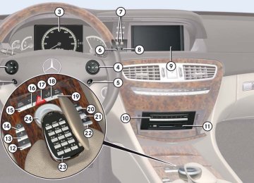
Item
1 Left side defroster vent, fixed 2 Left side air vent, adjustable 3 Left center air vent, adjustable 4 Thumbwheel for air volume control
for left center air vent
5 Thumbwheel for air volume control
for right center air vent
6 Right center air vent, adjustable 7 Right side air vent, adjustable 8 Right side defroster vent, fixed 9 Automatic climate control panel a Left rear center air vent, adjustable b Right rear center air vent, adjustable c Thumbwheel for right rear center air
vents
d Thumbwheel for left rear center air
vents
Controls in detail Air vents
Please comply with the following instruc- tions in order for the automatic climate control to function optimally: 앫 Keep the air intake grille in front of the windshield free of snow, leaves, sticks, and any other debris.
앫 Always keep all air vents and grilles in the passenger compartment free from obstruction.
489
Controls in detail Air vents
Opening and closing air vents
i For draft-free ventilation, move the sliders for the center air vents 3 and 6 (컄 page 488) to the middle position.
Center air vents 왘 Opening: Turn thumbwheels 4
and 5 upward (컄 page 488).
왘 Closing: Turn thumbwheels 4 and 5
downward.
Side air vents 왘 Opening: Turn thumbwheels next to
side air vents 2 and 7 upward (컄 page 488).
왘 Closing: Turn thumbwheels down-
ward.
Rear center console air vents 왘 Increasing/decreasing air volume: Turn thumbwheel c or d to the left or right (컄 page 488).
490
i The temperature at the air vents a and b (컄 page 488) for rear passenger compartment will be approximately the same as at the dash- board center air vents.
Ventilated storage compartment
The storage compartment under the front armrest can be ventilated when the auto- matic climate control is switched on.
! Extreme temperatures can occur in the stor- age compartment. Switch off the air vents in the storage compartment while the heating is switched on if you are transporting heat-sensi- tive items in the compartment. Keep the air vents free of obstruction.
1 Switching ventilation off 2 Switching ventilation on The air volume is dependent on the setting of: 앫 air distribution control 앫 air volume control 앫 air vents in the dashboard The air temperature is about the same as that of the dashboard air vents. It cannot be regulated separately.
왔 Automatic climate control
Controls in detail Automatic climate control
Automatic climate control panel
Item
Item
Item
1 AUTO mode for air distribution and
volume, left
2 Temperature control, left 3 Manual fan speed adjustment, left 4 Front defroster
5 Air recirculation 6 Automatic climate control on/off 7 Residual engine heat and ventilation
9 Manual fan speed adjustment, right a Temperature control, right b AUTO mode for air distribution and
(REST)
8 Rear window defroster
volume, right
491
Controls in detail Automatic climate control
i If you have the air distribution and air vol- ume automatically controlled, you can adjust the temperature, footwell temperature and air flow. The following basic settings are recommended: 앫 Automatic air distribution control
(컄 page 491)
앫 Temperature: 72°F (22°C) (컄 page 494) 앫 Footwell temperature: 0 (컄 page 274) 앫 Air flow: focused (컄 page 275) The automatic climate control is operation- al whenever the engine is running. You can operate the climate control system in ei- ther the automatic or manual mode. The system cools or heats the interior depend- ing on the selected interior temperature and the current outside temperature. It can only function optimally when you are driving with the windows and the tilt/slid- ing sunroof closed. It is possible to completely deactivate the climate control system (컄 page 493).
492
Nearly all dust particles, pollutants and odors are filtered out before outside air en- ters the passenger compartment through the air distribution system.
Warning!
Follow the recommended settings for heat- ing and cooling given on the following pages and in the “COMAND automatic climate control” section (컄 page 269). Otherwise the windows could fog up, impairing visibili- ty and endangering you and others.
Warning!
Severe conditions (e.g. strong air pollution) may require replacement of the filter before its scheduled replacement interval. A clogged filter will reduce the air volume to the interior and the windows could fog up, impairing visibility and endangering you and others. Have a clogged filter replaced as soon as possible at an authorized Mercedes-Benz Center.
i If the vehicle interior is hot, ventilate the in- terior before driving off, see “Summer opening feature” (컄 page 404). The automatic climate control will then adjust the interior temperature to the set value much faster. Keep the air intake grille in front of the wind- shield free of snow, leaves, sticks, and any other debris.
The following automatic climate control functions can be operated via COMAND:
Function Temperature Air distribution Air volume Switching off cooling (“AC OFF”) Central climate control (“Mono”) Footwell temperature Air flow from air vents
Page 270
271
271
272
273
274
275Deactivating climate control system
Warning!
When the automatic climate control is switched off, the outside air supply and cir- culation are also switched off. Only choose this setting for a short time. Otherwise the windows could fog up, impairing visibility and endangering you and others.
왘 Deactivating: Press button ´
(컄 page 491) up or down. The indicator lamp on the button comes on. You will see “Climate Con- trol OFF” in the COMAND display. 왘 Reactivating: Press button ´
(컄 page 491) up or down. The indicator lamp on the button goes out. You will see the previous settings in the COMAND display.
Controls in detail Automatic climate control
Operating climate control system in automatic mode
Air distribution and air volume is adjusted automatically by the automatic climate control system. You can also adjust the settings for air distribution and air volume manually.
i In automatic mode, cooling with dehumidify is switched on. This function can be switched off if necessary (컄 page 272).
Activating 왘 Press button U (컄 page 491) up or
down. The indicator lamp on the button comes on.
493
Controls in detail Automatic climate control
Deactivating 왘 Press button U (컄 page 491) up or
down.
or 왘 Adjust air distribution (컄 page 271). or 왘 Adjust air volume (컄 page 494).
The indicator lamp on button U goes out. The automatic function is switched off. You can adjust the air distribution (컄 page 271) or air volume (컄 page 494) manually.
494
Setting temperature
Adjusting air volume
Use temperature controls %$ 2 and a (컄 page 491) in the center con- sole or COMAND (컄 page 270) to sepa- rately adjust the air temperature on each side of the passenger compartment. You should raise or lower the temperature set- ting in small increments, preferably start- ing at 72°F (22°C). The automatic climate control will adjust to the set temperature as fast as possible. 왘 Press temperature control %$ 2 and/or a (컄 page 491) upward or downward. The climate control system will corre- spondingly adjust the interior air tem- perature.
Use buttons Q (컄 page 491) in the cen- ter console or COMAND to separately ad- just the air volume on each side of the passenger compartment. 왘 Press button Q up to increase or
down to decrease air volume. The indicator lamps on buttons U (컄 page 491) goes out. The automatic function is switched off. The air volume is adjusted correspond- ing to the set blower speed.
Front defroster
You can use this setting to defrost the windshield, for example if it is iced up. You can also defog the windshield and the side windows.
i Keep this setting selected only until the windshield is clear again.
Activating 왘 Press button ; (컄 page 491) up or
down. The indicator lamp on the button comes on.
The air conditioning switches to the follow- ing functions automatically: 앫 most efficient blower speed and heat- ing power, depending on outside tem- perature
앫 air flows onto the windshield and the
front side windows
앫 the air conditioning compressor
switches on at outside temperatures above approximately 41°F (5°C) for air-drying
앫 the air recirculation mode is switched
off
Adjustments You can adjust the air volume and the tem- perature when the front defroster is switched on. The air flow will remain on the windshield and door windows. 왘 Press button Q up or down to in- crease or decrease air volume to the desired level. The air volume increases/decreases to the next higher/lower blower speed and heating switches to the tempera- ture that was set before the front de- froster was switched on. The indicator lamp on button ; goes out.
or 왘 Press temperature control %$ 2 and/or a (컄 page 491) upward or downward. Heating switches to the temperature that was set before the front defroster was switched on.
Controls in detail Automatic climate control
The indicator lamp on button ; goes out.
i The air conditioning compressor remains on even with the indicator lamp on button ; goes out. This helps to prevent windshield from fogging.
Deactivating 왘 Press button ; (컄 page 491) up or
down. The indicator lamp on the button goes out. The previous settings are once again in effect, except air recirculation mode stays off.
Windshield fogged on the outside 왘 Switch the windshield wipers on
(컄 page 400).
왘 Press button U (컄 page 491) up or
down. The indicator lamp on the button comes on.
495
Controls in detail Automatic climate control
Rear window defroster
Activating 왘 Switch on the ignition (컄 page 365). 왘 Press button < (컄 page 491) up or
down. The indicator lamp on the button comes on.
! The rear window defroster uses a large amount of power. To keep battery drain to a min- imum, switch off the defroster as soon as the rear window is clear.
Deactivating 왘 Press button < (컄 page 491) up or
down. The indicator lamp on the button goes out.
i The defroster is automatically deactivated after some time of operation depending on the outside temperature.
496
Warning!
i Maximum cooling MAXCOOL is only avail- able when the engine is running.
Any accumulation of snow and ice should be removed from the rear window before driv- ing. Visibility could otherwise be impaired, endangering you and others.
i If the rear window defroster switches off too soon and the indicator lamp goes out, this indi- cates that too many electrical consumers are op- erating simultaneously and the load on the battery is reducing available voltage. The system responds automatically by deactivating the rear window defroster.
Maximum cooling MAXCOOL (USA only)
If U is selected on both the left and right side and there is a high demand for cooling, the display “MAXCOOL” appears in the COMAND display. This provides the fastest possible cooling of the vehicle interior (when windows and tilt/sliding sunroof are closed).
Air recirculation mode
Switch to air recirculation mode to prevent unpleasant odors from entering the vehicle from the outside (e.g. before driving in a tunnel). This setting cuts off the intake of outside air and recirculates the air in the passenger compartment.
Warning!
Fogged windows impair visibility, endanger- ing you and others. If the windows begin to fog on the inside, switching off the air recirculation mode immediately should clear interior window fogging. If interior window fogging persists, make sure the air conditioning (컄 page 272) is activated, or press button ;.
왘 Activating: Press button ,
(컄 page 491) up or down. The indicator lamp on the button comes on.
i The air recirculation mode is activated auto- matically at high outside temperatures. The indicator lamp on button , is not lit when the air recirculation mode is automatically acti- vated. A quantity of outside air is added when the cool- ing demand is not at maximum. If the air conditioning has been turned off (컄 page 272) or the outside temperature is be- low 41°F (5°C), the air recirculation mode will not switch on automatically.
왘 Deactivating: Press button ,
(컄 page 491) up or down. The indicator lamp on the button goes out.
i The manually selected air recirculation mode is deactivated automatically: 앫 after 5 minutes if the outside temperature is
below approximately 41°F (5°C)
앫 after 5 minutes if the air conditioning is
turned off
앫 after 30 minutes if the outside temperature
is above approximately 41°F (5°C)
Controls in detail Automatic climate control
Air recirculation mode with conve- nience closing or opening feature
Warning!
Never operate the side windows and the tilt/sliding sunroof if there is the possibility of anyone being harmed by the closing pro- cedure.
When using the air recirculation mode with convenience closing feature, should the up- ward movement of a window be blocked by some obstruction including but not limited to arms, hands, fingers, etc., the automatic reversal feature will not operate.
In the event that the procedure causes po- tential danger, the closing of the side win- dows can be immediately halted by pressing the respective window switch. The closing of the tilt/sliding sunroof can be immediately halted by moving the tilt/sliding sunroof switch in the overhead control panel in any direction.
컄컄
497
Controls in detail Automatic climate control
컄컄
The closing of the side windows and the tilt/sliding sunroof can be reversed by again pressing and holding button ,.
왘 Convenience closing: Press button , for approximately 2 seconds. The side windows and/or tilt/sliding sunroof will close. You can release button , once the closing proce- dure has begun. The windows and tilt/sliding sunroof continue closing until they are fully closed. The indicator lamp on the button comes on. The air recirculation mode is activated. 왘 Convenience opening: Press button , for approximately 2 seconds.
The side windows and/or tilt/sliding sunroof will return to their previous po- sition. You can release button , once the opening procedure has be- gun. The windows and tilt/sliding sun- roof continue opening until they have reached their previous positions. The indicator lamp on the button goes out. The air recirculation mode is deactivat- ed.
i A window or tilt/sliding sunroof will only re- turn to its previous position if it has not been moved to another position using the respective window switch or tilt/sliding sunroof switch af- ter it was closed with button ,. A window or tilt/sliding sunroof that has been moved will remain in its current position if button , is used to reopen the remaining windows or tilt/sliding sunroof.
Residual engine heat and ventilation
With the engine switched off, it is possible to continue to heat or ventilate the interior. This feature makes use of the residual heat produced by the engine.
i If you switch on the residual heat function when outside temperatures are high, only the ventilation will be switched on.
i Regardless of the selected air volume, the blower operates at low speed when heating. In case of ventilation the blower operates at higher speed.
i How long the system will provide heating de- pends on 앫 the coolant temperature 앫 the temperature set by the operator
498
Activating 왘 Switch off the ignition (컄 page 365). 왘 Press button T (컄 page 491) up or
down. The indicator lamp on the button comes on.
Deactivating 왘 Press button T (컄 page 491) up or
down. The indicator lamp on the button goes out.
i The residual heat is automatically turned off: 앫 when the ignition is switched on 앫 after approximately 30 minutes 앫 if the battery voltage drops 앫 if the coolant temperature is too low
Controls in detail Automatic climate control
499
Controls in detail Trunk
Warning!
Make sure the trunk is closed when the en- gine is running and while driving. Among other dangers, deadly carbon monoxide (CO) gases may enter the vehicle interior re- sulting in unconsciousness and death.
Opening trunk
You can open the trunk if the vehicle is sta- tionary. A minimum height clearance of 6.0 ft (1.8 m) is required to open the trunk lid.
! The trunk lid swings open upwards automat- ically. Always make sure that there is sufficient overhead clearance. To stop the opening procedure, press button Š on the SmartKey or SmartKey with KEYLESS-GO*.
500
Opening trunk from outside
Opening trunk from inside
1 Trunk lid handle 왘 Press and hold button Š on the
1 Remote trunk opening/closing switch 왘 Press and hold switch 1 until the
SmartKey or SmartKey with KEYLESS-GO* until trunk unlocks and begins to open.
or 왘 Pull on handle 1.