- 2012 Mercedes-Benz CL Class Owners Manuals
- Mercedes-Benz CL Class Owners Manuals
- 2008 Mercedes-Benz CL Class Owners Manuals
- Mercedes-Benz CL Class Owners Manuals
- 2011 Mercedes-Benz CL Class Owners Manuals
- Mercedes-Benz CL Class Owners Manuals
- 2007 Mercedes-Benz CL Class Owners Manuals
- Mercedes-Benz CL Class Owners Manuals
- 2002 Mercedes-Benz CL Class Owners Manuals
- Mercedes-Benz CL Class Owners Manuals
- 2013 Mercedes-Benz CL Class Owners Manuals
- Mercedes-Benz CL Class Owners Manuals
- 2004 Mercedes-Benz CL Class Owners Manuals
- Mercedes-Benz CL Class Owners Manuals
- 2000 Mercedes-Benz CL Class Owners Manuals
- Mercedes-Benz CL Class Owners Manuals
- 2010 Mercedes-Benz CL Class Owners Manuals
- Mercedes-Benz CL Class Owners Manuals
- 2006 Mercedes-Benz CL Class Owners Manuals
- Mercedes-Benz CL Class Owners Manuals
- 2003 Mercedes-Benz CL Class Owners Manuals
- Mercedes-Benz CL Class Owners Manuals
- 2005 Mercedes-Benz CL Class Owners Manuals
- Mercedes-Benz CL Class Owners Manuals
- 2009 Mercedes-Benz CL Class Owners Manuals
- Mercedes-Benz CL Class Owners Manuals
- 2001 Mercedes-Benz CL Class Owners Manuals
- Mercedes-Benz CL Class Owners Manuals
- Download PDF Manual
-
In vehicles without KEYLESS-GO*: The vehicle must be unlocked.
trunk is opened. The indicator lamp in switch 1 comes on and remains lit until the trunk is closed.
To interrupt the opening procedure: 왘 Release switch 1.
Trunk opening-height restriction The trunk lid opening height can be limited when transporting goods on a roof rack (e.g. presence of an optional MB sport lug- gage container). When activated, the trunk opens to approximately the height of the roof edge. 왘 Activate the limiting opening height of
trunk lid using the COMAND system (컄 page 268).
Closing trunk
i Do not place the SmartKey in the open trunk. You may lock yourself out.
i If the vehicle was previously centrally locked, the trunk will lock automatically after closing it. All turn signal lamps flash three times to confirm locking. Vehicles with KEYLESS-GO*: To prevent a possi- ble inadvertent lockout, the trunk will open auto- matically if a SmartKey with KEYLESS-GO* is recognized inside the vehicle or in the trunk. The vehicle is only locked when the turn signals flash three times. If you are carrying a second
Controls in detail Trunk
SmartKey with KEYLESS-GO* with you, you can still lock the vehicle.
Warning!
To prevent possible personal injury, always keep hands and fingers away from the trunk lid opening when closing the trunk. Be espe- cially careful when small children are around.
When leaving the vehicle, always remove the SmartKey or SmartKey with KEYLESS-GO* from the starter switch, take it with you, and lock the vehicle. Do not leave children unat- tended in the vehicle, or with access to an unlocked vehicle. A child’s unsupervised ac- cess to a vehicle could result in an accident and/or serious personal injury.
Closing trunk from outside manually
1 Handle 왘 Lower trunk lid by pulling firmly on
handle 1.
왘 Close the trunk with hands placed flat
on the trunk lid.
The power closing assist automatically en- sures that the trunk lid is pulled closed completely (컄 page 363).
501
Controls in detail Trunk
Closing trunk from inside automatically
Warning!
Maintain sight of trunk area while operating door mounted switch. Monitor the closing procedure carefully to make sure no one is in danger of being injured.
To interrupt the closing procedure, release the door mounted remote trunk open- ing/closing switch.
Even with the SmartKey or SmartKey with KEYLESS-GO* removed from the starter switch or the SmartKey with KEYLESS-GO* removed from the vehicle, the remote trunk opening/closing switch can be operated.
Therefore, do not leave children unattended in the vehicle, or with access to an unlocked vehicle. A child’s unsupervised access to a vehicle could result in an accident and/or serious personal injury.
502
i If the trunk lid comes into contact with an object while closing (e.g. luggage that has been piled too high) in the upper motion sequence, the closing procedure is stopped and the trunk re- opens slightly.
1 Remote trunk opening/closing switch 왘 Press and hold switch 1 until the
trunk is closed. The indicator lamp in the switch goes out when the trunk is closed.
To interrupt the closing procedure: 왘 Release switch 1.
i You can also close the trunk by hand.
Closing trunk from outside automatically
Warning!
Monitor the closing procedure carefully to make sure no one is in danger of being in- jured. To prevent possible personal injury, always keep hands and fingers away from the trunk lid opening when closing the trunk. Be especially careful when small children are around. To stop the closing procedure, do one of the following: 앫 press button Š on the SmartKey or
SmartKey with KEYLESS-GO
앫 press the trunk opening/closing switch
(on the driver’s door)
앫 press the trunk closing switch 앫 press the KEYLESS-GO locking/closing
switch*
앫 pull the trunk lid handle
Even with the SmartKey or SmartKey with KEYLESS-GO* removed from the starter switch or the SmartKey with KEYLESS-GO* removed from the vehicle, the remote trunk opening/closing switch can be operated. Therefore, do not leave children unattended in the vehicle, or with access to an unlocked vehicle. A child’s unsupervised access to a vehicle could result in an accident and/or serious personal injury.
Vehicles without KEYLESS-GO* 1 Trunk closing switch
Controls in detail Trunk
Closing trunk and locking vehicle from outside (vehicles with KEYLESS-GO*) You can close the trunk and lock the vehi- cle simultaneously from the outside using the KEYLESS-GO locking/closing switch.
Vehicles with KEYLESS-GO* 1 Trunk closing switch 왘 Press trunk closing switch 1 briefly.
The trunk closes.
i If the trunk lid comes into contact with an object while closing (e.g. luggage that has been piled too high) in the upper motion sequence, the closing procedure is stopped and the trunk re- opens slightly.
i You can also close the trunk by hand.
1 KEYLESS-GO locking/closing switch 왘 Make sure you have the SmartKey with
KEYLESS-GO with you. 왘 Press switch 1 briefly.
컄컄
503
Controls in detail Trunk
컄컄
With both doors closed: 앫 The locking knobs in the doors
move down.
앫 The trunk starts to close automati-
cally.
앫 All turn signal lamps flash three
times to confirm locking once the trunk has closed completely.
앫 An acoustic signal sounds three
times.
앫 The anti-theft alarm system is
armed.
i If the trunk lid comes into contact with an object while closing (e.g. luggage that has been piled too high) in the upper motion sequence, the closing procedure is stopped and the trunk re- opens slightly.
i You can also close the trunk by hand.
504
Trunk emergency release
With the emergency release button, the trunk can be opened from inside the trunk.
Illumination of the emergency release but- ton: 앫 The button will flash for 30 minutes af-
ter opening the trunk.
앫 The button will flash for 60 minutes af-
ter closing the trunk.
i The emergency release button does not open the trunk if the vehicle battery is dis- charged or disconnected.
1 Emergency release button 왘 Briefly press emergency release
button 1. The trunk opens.
i The emergency release button unlocks and opens the trunk while the vehicle is standing still or in motion.
Valet locking
i To deny any unauthorized person access to the trunk, e.g. when you valet park the vehicle, lock it separately with the mechanical key. Leave only the SmartKey or SmartKey with KEYLESS-GO* less its mechanical key with the vehicle.
1 Neutral position 2 Locked
왘 Close the trunk (컄 page 501). 왘 Remove the mechanical key from the
SmartKey (컄 page 684).
왘 Insert the mechanical key in the trunk
lid lock.
왘 Turn the mechanical key clockwise to
position 2 to lock the trunk.
The trunk remains locked even when the vehicle is centrally unlocked.
i You can only cancel the separate trunk lock- ing mode by means of the mechanical key. 왘 Insert the mechanical key in the trunk
lid lock.
왘 Turn the mechanical key counterclock- wise to neutral position 1 to unlock the trunk. You can now open the trunk (컄 page 500).
Controls in detail Trunk
505
Controls in detail Power tilt/sliding sunroof
Opening and closing power tilt/sliding sunroof
Warning!
When closing the tilt/sliding sunroof, make sure that there is no danger of anyone being harmed by the closing procedure.
If the tilt/sliding sunroof encounters an ob- struction that blocks its path in a circum- stance where you are closing the tilt/sliding sunroof by moving the tilt/sliding sunroof switch past the resistance point, or by pressing and holding button ‹ on the SmartKey, by pressing and holding the sen- sor surface (vehicles with KEYLESS-GO*) on the outside door handle, the automatic re- versal function will not operate.
The opening/closing procedure of the tilt/sliding sunroof can be immediately halt- ed by releasing the switch or, if the switch was moved past the resistance point and re- leased, by moving the switch in any direc- tion.
506
Do not open the tilt/sliding sunroof if there is snow or ice on the roof, as this could result in malfunctions. If you cannot open or close the tilt/sliding sun- roof due to a malfunction contact Roadside As- sistance or an authorized Mercedes-Benz Center. ! Please keep in mind that weather conditions can sometimes change rapidly. Make sure to close the tilt/sliding sunroof when leaving the vehicle. If water enters the vehicle interior, vehi- cle electronics could be damaged which is not covered by the Mercedes-Benz Limited Warranty.
i When the tilt/sliding sunroof is open, reso- nance noises may result in addition to the usual wind noises. They are caused by minimal pres- sure changes in the passenger compartment. To reduce or eliminate these noises, change the po- sition of the tilt/sliding sunroof or open a side window slightly.
The tilt/sliding sunroof is made out of glass. In the event of an accident, the glass may shatter. This may result in an opening in the roof.
In a vehicle rollover, occupants not wearing their seat belts or not wearing them properly may be thrown out of the opening. Such an opening also presents a potential for injury for occupants wearing their seat belts properly as entire body parts or portions of them may protrude from the passenger compartment.
When leaving the vehicle, always remove the SmartKey or SmartKey with KEYLESS-GO* from the starter switch, take it with you, and lock the vehicle. Do not leave children unat- tended in the vehicle, or with access to an unlocked vehicle. A child’s unsupervised ac- cess to a vehicle could result in an accident and/or serious personal injury.
! To avoid damaging the seals, do not trans- port any objects with sharp edges which can stick out of the tilt/sliding sunroof.
i You can also open or close the tilt/sliding sunroof using the SmartKey, see “Summer open- ing feature” (컄 page 404) and “Convenience closing feature” (컄 page 404). Depending on current position, the tilt/sliding sunroof may also open or close when the air recirculation button , (컄 page 491) is pressed and held for 2 seconds.
i If PRE-SAFE® has been activated, the tilt/sliding sunroof closes automatically until only a small gap remains.
i With the SmartKey in starter switch position 0 or removed from the starter switch, the tilt/sliding sunroof can be operated 앫 until you open the driver’s or passenger door 앫 for up to approximately 5 minutes
1 Push back to slide sunroof open 2 Push forward to slide sunroof closed 3 Push up to raise sunroof at rear 4 Pull down to lower sunroof at rear With the sunroof closed or tilted open, a screen can be slid into the roof opening to help provide shade. When sliding the sun- roof open, the screen will also retract.
Controls in detail Power tilt/sliding sunroof
왘 Switch on the ignition (컄 page 365). 왘 To open, close, raise or lower, move the
switch to resistance point in the re- quired direction 1 to 4 until the tilt/sliding sunroof has reached the de- sired position.
왘 Express-operation: To open, close, raise or lower, move the switch past the resistance point in the required direction 1 to 4 and release. The tilt/sliding sunroof opens or closes completely.
왘 Stopping during Express-operation:
Move the switch in any direction.
i If the movement of the tilt/sliding sunroof is blocked during the closing procedure, the sun- roof will stop and reopen slightly.
507
Controls in detail Power tilt/sliding sunroof
Synchronizing
The tilt/sliding sunroof must be synchro- nized 앫 if the tilt/sliding sunroof can only be
opened with a jerking motion
앫 after a malfunction
! Do not open the tilt/sliding sunroof com- pletely if it is not aligned. Otherwise you could damage the tilt/sliding sunroof.
왘 Switch on the ignition (컄 page 365). 왘 Press and hold the sunroof switch in
the direction of arrow 3 until the tilt/sliding sunroof is fully raised at the rear.
왘 Keep holding the sunroof switch in the direction of arrow 3 for approximately 1 second.
왘 Check the Express-operation feature
(컄 page 507). If the tilt/sliding sunroof opens com- pletely, the sunroof is synchronized. Otherwise repeat the above steps.
508
왔 Loading and storing Loading instructions
The total load weight including vehicle oc- cupants and luggage/cargo should not exceed the load limit as indicated on the corresponding placard located on the driv- er’s door B-pillar (컄 page 564).
Warning!
Always fasten items being carried as secure- ly as possible using cargo tie-down hooks and fastening materials appropriate for the weight and size of the load.
In an accident, during hard braking or sud- den maneuvers, loose items will be thrown around inside the vehicle and can cause in- jury to vehicle occupants unless the items are securely fastened in the vehicle.
To help avoid personal injury during a colli- sion or sudden maneuver, exercise care when transporting cargo. Put luggage or car- go in the trunk if possible.
Do not pile luggage or cargo higher than the seat backs. Do not place anything on the rear-window shelf.
Never drive vehicle with trunk open. Deadly carbon monoxide (CO) gases may enter ve- hicle interior resulting in unconsciousness and death.
Controls in detail Loading and storing
Storage compartments
Warning!
To help avoid personal injury during a colli- sion or sudden maneuver, exercise care when storing objects in the vehicle. Put lug- gage or cargo in the trunk if possible. Do not pile luggage or cargo higher than the seat backs.
Parcel nets cannot secure hard or heavy ob- jects.
Keep compartment lids closed. This will help to prevent stored objects from being thrown about and injuring vehicle occupants during 앫 braking 앫 vehicle maneuvers or 앫 an accident.
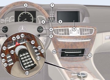
i An overview of the storage compartments can be found on (컄 page 34).
509
Controls in detail Loading and storing
Storage compartments in the front passenger compartment
왘 Opening: Press glove box lid
release 1.
Storage compartments in the front armrest
Glove box
왘 Closing: Push the lid up. 왘 Locking: Insert the mechanical key
into the glove box lock and turn it clockwise to position 3.
왘 Unlocking: Insert the mechanical key into the glove box lock and turn it coun- terclockwise to position 2.
1 Glove box lid release 2 Unlocking glove box 3 Locking glove box
The glove box can be unlocked and locked with the mechanical key (컄 page 684).
510
1 Storage tray/telephone* compartment 2 Storage compartment 왘 Opening storage tray/telephone* compartment: Press button 1 and swing armrest to left or right side. 왘 Opening storage compartment:
Press button 2 and swing center arm- rest upward.
Storage compartments below the front seats
Eyeglasses compartment
Parcel net in front passenger footwell
Controls in detail Loading and storing
1 Tab 2 Compartment cover 왘 Opening: Pull tab 1 upward and fold
cover 2 forward.
1 Eyeglasses compartment mark 왘 Opening: Press mark 1. 왘 Closing: Swing eyeglasses compart-
ment upward until it engages.
Warning!
The parcel net is intended for storing light-weight items only.
Heavy objects, objects with sharp edges or fragile objects may not be transported in the parcel net. In an accident, during hard brak- ing, or sudden maneuvers, they could be in- jury to vehicle occupants.
The parcel net cannot protect transported goods in the event of an accident.
511
Controls in detail Loading and storing
A small convenience parcel net is located in the front passenger footwell. It is for small and light items, such as road maps, mail, etc.
Storage compartments in rear passenger compartment
Storage compartment between rear seats
Armrest with integrated storage compartment
! Before storing the armrest in the backrest, close the storage compartment cover.
! Do not sit on or lean your body weight against the armrest when it is folded down, as you could otherwise damage it.
1 Handle 왘 Opening: Pull handle 1 backward in
the direction of arrow.
1 Release catch 왘 Opening: Pull release catch 1 and
swing the cover upward.
512
Rear storage box
Cup holders
! Do not sit on or lean your body weight against the armrest when it is folded down, as you could otherwise damage it.
Warning!
In order to help prevent spilling liquids on vehicle occupants and/or vehicle equip- ment, only use containers that fit into the cup holder. Use lids on open containers and do not fill containers to a height where the contents, especially hot liquids, could spill during braking, vehicle maneuvers, or in an accident. Liquids spilled on vehicle occu- pants may cause serious personal injury. Liquids spilled on vehicle equipment may cause damage not covered by the Mercedes-Benz Limited Warranty.
When not in use, keep the cup holders closed. An open cup holder may cause injury to you or others when contacted during braking, vehicle maneuvers, or in an acci- dent.
1 Handle 2 Cover 왘 Fold down rear center armrest. 왘 Pull handle 1 upward in the direction
of arrow.
왘 Swing down cover 2.
Controls in detail Loading and storing
Keep in mind that objects placed in the cup holder may come loose during braking, vehi- cle maneuvers, or in an accident and be thrown around in the vehicle interior. Objects thrown around in the vehicle interi- or may cause an accident and/or serious personal injury.
Cup holder in front center console
1 Mark 2 Handle 왘 Opening: Press mark 1 on the front. 왘 Closing: Fold cover in until it engages.
컄컄
513
Controls in detail Loading and storing
컄컄
i You can remove the cup holder to clean it. Only clean it using clear, lukewarm water. 왘 Removing: Pull cup holder out by pull- ing silver handle 2 upward in direction of arrow.
왘 Inserting: Press downward until it en- gages. While doing so, make sure that the word “Front” is in the proper instal- lation position.
514
Cup holder in rear
Trunk
Storage spaces under trunk floor
1 Compartment mark 왘 Opening: Press mark 1 on the front.
1 Storage space 2 Handle 3 Trunk floor cover 왘 Lift up trunk floor cover 3 and engage the cover handle 2 in upper edge of trunk.
Retaining hooks A hook is located on the upper edge of the trunk and can be used to attach cargo items such as bags.
Parcel net in trunk There is a parcel net on the right trunk side wall to secure loads.
Retainer for Operator’s Manual pouch
1 Tab 2 Retaining hook 왘 Pull tab 1 of retaining hook 2 down.
! Do not use the retaining hooks to tie down cargo.
1 Hook-and-loop fastener 2 Operator’s Manual pouch Use hook-and-loop fastener 1 to fasten Operator’s Manual pouch 2 in place.
Controls in detail Loading and storing
515
Controls in detail Useful features
Sun visors
Warning!
Glare from front 왘 Swing sun visor 1 down.
Glare from front and sides
Ashtray
Warning!
Do not use the vanity mirror while driving.
Keep the vanity mirrors in the sun visors closed while vehicle is in motion. Reflected glare can endanger you and others.
! Close vanity mirror cover 2 (if open) before you disengage sun visor 1 from the mounting and pivot it to the side. 왘 Disengage sun visor 1 from the
mounting.
왘 Pivot sun visor 1 to the side.
Vanity mirror in sun visor 왘 To use vanity mirror, lift up cover 2.
Vanity mirror lamp 3 comes on.
i If you disengage sun visor 1 from the mounting, vanity mirror lamp 2 will switch off.
Document holder You can use the plastic tab of document holder 4 to hold admission tickets, park- ing passes, or similar items in place.
1 Sun visor 2 Vanity mirror cover 3 Vanity mirror lamp 4 Document holder
516
Remove ashtray only with vehicle standing still. Engage the electronic parking brake to secure vehicle from movement. Set auto- matic transmission to P. With the automatic transmission set to P, turn off the engine.
1 Button for disengaging ashtray 2 Cover plate
Opening ashtray 왘 Press mark on cover plate 2 forward.
Cigarette lighter
Removing ashtray insert 왘 Push sliding button 1 to the left.
The ashtray is disengaged and slides out a short way.
왘 Remove the insert from the ashtray
frame.
Reinstalling ashtray insert 왘 Install the insert by pushing it back into
the frame until it engages.
Closing ashtray 왘 Briefly press mark on cover plate 2
forward.
Warning!
Never touch the heating element or sides of the lighter; they are extremely hot. Hold the knob only.
Make sure that any children traveling with you do not injure themselves or start a fire with the hot cigarette lighter.
When leaving the vehicle, always remove the SmartKey or SmartKey with KEYLESS-GO* from the starter switch, take it with you, and lock the vehicle. Do not leave children unat- tended in the vehicle, or with access to an unlocked vehicle. A child’s unsupervised ac- cess to a vehicle could result in an accident and/or serious personal injury.
Controls in detail Useful features
1 Cigarette lighter 왘 Open the cover plate (컄 page 516). 왘 Switch on the ignition (컄 page 365). 왘 Push in cigarette lighter 1.
The lighter will pop out automatically when hot.
517
Controls in detail Useful features
! The lighter socket can be used to accommo- date 12V DC electrical accessories (up to a max- imum of 85 W) designed for use with the standard “cigarette lighter” plug type. Keep in mind, however, that connecting accessories to the lighter socket (for example extensive con- necting and disconnecting, or using plugs that do not fit properly) can damage the lighter socket. With the socket damaged, the lighter may no longer be able to be placed in the heating (pushed-in) position, or the lighter may pop out too early with the lighter not hot enough.
i If the engine is off and the cigarette lighter is being used extensively, the vehicle battery may become discharged.
518
Floormats*
Warning!
Whenever you are using floormats, make sure there is enough clearance and that the floormats are securely fastened.
Floormats should always be securely fas- tened using the eyelets and the retainer pins.
Before driving off, check that the floormats are securely in place and adjust them if nec- essary. A loose floormat could slip and hinder proper functioning of the pedals.
Do not place several floormats on top of each other as this may impair pedal movement.
i To install or remove the floormat more easi- ly, move the driver’s seat or front passenger seat as far to the rear as possible (컄 page 368).
1 Retainer pin 2 Eyelet
Removing 왘 Pull floormat off of retainer pins 1. 왘 Remove the floormat.
Installing 왘 Lay down the floormat in the respective
footwell.
왘 Press the floormat eyelets 2 onto re-
tainer pins 1.
Telephone*
Warning!
Never operate radio transmitters equipped with a built-in or attached antenna (i.e. with- out being connected to an external antenna) from inside the vehicle while the engine is running. Doing so could lead to a malfunc- tion of the vehicle’s electronic system, pos- sibly resulting in an accident and/or serious personal injury.
Radio transmitters, such as a portable tele- phone or a citizens band unit, should only be used inside the vehicle if they are con- nected to an antenna that is installed on the outside of the vehicle. The external antenna must be approved by Mercedes-Benz. Please contact an autho- rized Mercedes-Benz Center for informa- tion on the installation of an approved external antenna. Refer to the radio trans- mitter operation instructions regarding use of an external antenna.
Warning!
Please do not forget that your primary re- sponsibility is to drive the vehicle. A driver’s attention to the road must always be his/her primary focus when driving. For your safety and the safety of others, we rec- ommend that you pull over to a safe location and stop before placing or taking a tele- phone call. If you choose to use the mobile phone1 while driving, please use the hands-free de- vice and only use the mobile phone when road, weather and traffic conditions permit. Some jurisdictions prohibit the driver from using a mobile telephone while driving a ve- hicle.
Only operate the COMAND (Cockpit Man- agement and Data System)1 if road, weather and traffic conditions permit.
1 Observe all legal requirements.
Controls in detail Useful features
Bear in mind that at a speed of just 30 mph (approximately 50 km/h), your vehicle is covering a distance of 44 feet (approximate- ly 14 m) every second.
i Various mobile phone cradles can be in- stalled in the front center armrest, see separate installation instructions for the mobile phone cradle. These mobile phone cradles can be ob- tained from an authorized Mercedes-Benz Center. The functions and services available to you while using the mobile phone depend on your service provider and the type of mobile phone you are using. See also separate operating manual for in- structions on how to use your mobile phone.
519
Controls in detail Useful features
When the mobile phone is inserted in the cradle, you can operate the telephone us- ing the following devices: 앫 mobile phone keypad 앫 COMAND telephone keypad
(컄 page 140)
앫 buttons s and t on the multi- function steering wheel (컄 page 283)
앫 Voice Control (컄 page 308) 앫 Bluetooth® headset (컄 page 153) Please note that these functions are only available with Mercedes-Benz approved mobile phones. Please contact an autho- rized Mercedes-Benz Center for informa- tion on features available for your mobile phone of choice. 왘 Open telephone compartment
(컄 page 510).
520
Inserting mobile phone in mobile phone cradle Once the mobile phone has been inserted in the mobile phone cradle, you have to use the hands-free device or Bluetooth headset to respond during phone calls.
! Do not try to remove the mobile phone along with the cradle. You could otherwise damage the mobile phone cradle. 왘 If applicable, remove the cover for the external antenna connection from the back of the mobile phone and store it in a safe place. Be sure to comply with the mobile phone’s operating instructions, as well.
Example illustration 1 Insert the mobile phone 2 Connector contact 3 Mobile phone cradle 왘 Slide the lower end of the mobile phone
into connector contact 2 on cradle 3.
왘 Push the top of the mobile phone in di- rection of arrow 1, until the lug on the mobile phone release button engages. The mobile phone is connected to the network via the external antenna.
The mobile phone is linked to the hands-free device and the multifunc- tion steering wheel. The battery is charged depending on its charge status and the position of the SmartKey in the starter switch. The charge procedure will be indicated in the mobile phone’s display.
You can place or receive phone calls. You can control other functions of the mobile phone via the COMAND (컄 page 137), instrument cluster control system (컄 page 294) or Voice Control (컄 page 308).
i When you take the SmartKey or SmartKey with KEYLESS-GO* out of the starter switch, the mobile phone remains switched on for approxi- mately 10 minutes. If you place or receive a call during this time, the mobile phone switches off 10 minutes after the call has been completed.
Removing mobile phone from mobile phone cradle
Example illustration 1 Release catch for mobile phone 2 Mobile phone cradle
i When using a flip-style mobile phone, open flip top before removing from the cradle while a call is connected. Otherwise, the call will be dis- connected. 왘 Press release catch in direction of
arrow 1 and take mobile phone out of mobile phone cradle 2.
Controls in detail Useful features
Changing mobile phone cradle If you require a different cradle for your mobile phone, remove the present cradle before installing a new one.
Removing an existing mobile phone cradle
Example illustration 1 To release the mobile phone cradle 2 To remove the mobile phone cradle 3 Mobile phone cradle 왘 Press release button in direction of
arrow 1 and take mobile phone cradle 3 out in direction of arrow 2.
521
Controls in detail Useful features
Installing a different mobile phone cradle
Tele Aid
! The initial activation of the Tele Aid system may only be performed by completing the sub- scriber agreement and placing an acquaintance call using the Information button ¡. Failure to complete either of these steps will result in a system that is not activated. If you have any questions regarding activation, please call the Response Center at 1-800-756-9018 (in the USA) or 1-888-923-8367 (in Canada).
Example illustration 1 Contact plate 2 Recesses 3 Mobile phone cradle 왘 Insert mobile phone cradle 3 into
recesses 2 of contact plate 1.
왘 Push mobile phone cradle 3 forward
until it engages.
The Tele Aid system (Telematic Alarm Identification on De- mand) The Tele Aid system consists of three types of response: 앫 automatic and manual emergency 앫 Roadside Assistance, and 앫 information
522
The Tele Aid system is operational provid- ing that the vehicle’s battery is charged, properly connected, not damaged and mo- bile phone and GPS coverage are available.
i The Tele Aid system utilizes the mobile phone network for communication and the GPS (Global Positioning System) satellites for vehicle location. If either of these signals are unavail- able, the Tele Aid system may not function and if this occurs, assistance must be summoned by other means.
The speaker volume of a Tele Aid call can be adjusted when using the volume control on the multifunction steering wheel. To raise, press button æ and to lower, press button ç or use the COMAND volume thumbwheel , on the lower part of the front center console (컄 page 94). 왘 To activate, press the SOS button, the
Roadside Assistance button • or the Information button ¡, depend- ing on the type of response required.
i The SOS button is located above the interior rear view mirror (컄 page 525). The Roadside Assistance button • and the Information button ¡ are located below the center armrest cover (컄 page 525). Shortly after the completion of your Tele Aid acquaintance call, you will receive a user ID and password. By visiting www.mbusa.com and selecting “Tele Aid” (USA only), you will have access to account information, remote door unlock and more.
System self-check Initially, after switching on the ignition, malfunctions are detected and indicated. If a malfunction is detected, the indicator lamps in the SOS button, the Roadside As- sistance button • and the Information button ¡ stay on longer than 10 seconds or do not come on. The mes- sage “Tele Aid Not Activated” or “Tele Aid Inoperative” appears in the multifunction display.
Warning!
If the indicator lamps in the SOS button, in the Roadside Assistance button • and/or in the Information button ¡ do not come on during the system self-check, or if any of these indicators remain illuminat- ed continuously in red and/or the message “Tele Aid Not Activated” or “Tele Aid Inoper- ative” is displayed in the multifunction dis- play after the system self-check, a malfunction in the system has been detect- ed.
If a malfunction is indicated as outlined above, the system may not operate as ex- pected. Have the system checked at the nearest Mercedes-Benz Center as soon as possible.
Emergency calls An emergency call is initiated automatically following an accident in which the emergency tensioning devices (ETDs) or air bags deploy.
Controls in detail Useful features
An emergency call can also be initiated manually by opening the cover next to the interior rear view mirror labeled SOS, then briefly pressing the button located under the cover. For instructions on initiating an emergency call manually (컄 page 525). Once the emergency call is in progress, the indicator lamp in the SOS button will begin to flash. The message: 앫 “Connecting Call” appears in the multi-
function display
앫 “Emergency Call Activated” appears in
the COMAND display
and the audio system is muted. When the connection is established, the message: 앫 “Call Connected” appears in the multi-
function display
앫 “Emergency Call Activated” appears in
the COMAND display
523
Controls in detail Useful features
All information relevant to the emergency, such as the location of the vehicle (deter- mined by the GPS satellite location sys- tem), vehicle model, identification number and color are generated.
i During the emergency call message “Emer- gency Call Activated” is displayed, operation from COMAND is not possible. The automatic cli- mate control can be still adjusted using the switches on the climate control panel.
A voice connection between the Response Center and the occupants of the vehicle will be established automatically soon af- ter the emergency call has been initiated. The Response Center will attempt to deter- mine more precisely the nature of the acci- dent provided they can speak to an occupant of the vehicle.
i If no vehicle occupant responds, an ambu- lance will be sent to the vehicle immediately.
524
The message: 앫 “Call Failed” appears in the multifunc-
tion display for approximately 10 seconds
앫 A pop-up window with the message:
“Call could not be connected! Please dial 911 directly using the mobile telephone keypad.” appears in the COMAND dis- play. Confirm the message pressing n (컄 page 86).
Should this occur, assistance must be sum- moned by other means.
i During the emergency call the mobile phone is switched off automatically and must be switched back on to make a call.
i The “911” emergency call system is a public service. Using it without due cause is a criminal offense.
The Tele Aid system is available if 앫 it has been activated and is operation- al. Activation requires a subscription for monitoring services, connection, and cellular air time
앫 the relevant monitoring service and GPS coverage are available and pass the information on to the Response Center
앫 there is sufficient voltage in the vehicle
batteries
i Location of the vehicle on a map is only pos- sible if the vehicle is able to receive signals from the GPS satellite network and pass the informa- tion on to the Response Center.
Warning!
If the indicator lamp in the SOS button is flashing continuously and there was no voice connection to the Response Center established, then the Tele Aid system could not initiate an emergency call (e.g. the rele- vant mobile phone network is not available).
Initiating an emergency call manually
왘 Close cover 2 after the emergency
call is concluded.
Warning!
If you feel at any way in jeopardy when in the vehicle (e.g. smoke or fire in the vehicle, ve- hicle in a dangerous road location), please do not wait for voice contact after you have pressed the emergency button. Carefully leave the vehicle and move to a safe loca- tion. The Response Center will automatically contact local emergency officials with the vehicle’s approximate location if they receive an automatic SOS signal and cannot make voice contact with the vehicle occupants.
1 SOS button 2 Cover 왘 Briefly press button on cover 2 to
open. Cover 2 will open.
왘 Press SOS button 1 (for longer than
2 seconds). The indicator lamp in SOS button 1 will flash until the emergency call is concluded.
왘 Wait for a voice connection to the
Response Center.
Controls in detail Useful features
Roadside Assistance button • and Information button ¡ The Roadside Assistance button • and the Information button ¡ are located in the storage compartment below the front armrest (컄 page 510).
1 Information button ¡ 2 Roadside Assistance button •
525
Controls in detail Useful features
Roadside Assistance button • 왘 Press and hold Roadside Assistance
button • (for longer than 2 seconds). A call to a Mercedes-Benz Roadside As- sistance dispatcher will be initiated. The button will flash while the call is in progress. The message: 앫 “Connecting Call” appears in the
multifunction display
앫 “Roadside Assistance Activated” appears in the COMAND display
and the audio system is muted.
When the connection is established, the message: 앫 “Call Connected” appears in the multi-
function display
앫 “Roadside Assistance Activated” appears in the COMAND display
526
The Tele Aid system will transmit data gen- erating the vehicle identification number, model, color and location (subject to avail- ability of cellular and GPS signals). A voice connection between the Roadside Assistance dispatcher and the occupants of the vehicle will be established. 왘 Describe the nature of the need for as-
sistance.
The Mercedes-Benz Roadside Assistance dispatcher will either dispatch a qualified Mercedes-Benz technician or arrange to tow your vehicle to the nearest authorized Mercedes-Benz Center. For services such as labor and/or towing, charges may ap- ply. Refer to the Roadside Assistance Man- ual for more information. These programs are only available in the USA: 앫 Sign and Drive services: Services such as jump start, a few gallons of fuel or the replacement of a flat tire with the vehicle spare tire are obtainable.
i The indicator lamp in the Roadside Assis- tance button • remains illuminated in red for approximately 10 seconds during the system self-check after switching on the ignition (togeth- er with the SOS button and the Information button ¡). See system self-check (컄 page 523) if the indi- cator lamp does not come on in red or stays on longer than approximately 10 seconds. If the indicator lamp in the Roadside Assistance button • is flashing continuously and no voice connection to the Response Center was established, the Tele Aid system could not ini- tiate a Roadside Assistance call (e.g. the relevant mobile phone network is not available). The mes- sage: 앫 “Call Failed” appears in the multifunction
display for approximately 10 seconds
앫 “Call could not be connected!” appears in
the COMAND display. Confirm the message pressing n (컄 page 86).
Roadside Assistance calls can be terminated us- ing button t on the multifunction steering wheel or COMAND (컄 page 137).
Information button ¡ 왘 Press and hold Information button ¡ (for longer than 2 seconds). A call to the Customer Assistance Cen- ter will be initiated. The button will flash while the call is in progress. The message:
“Connecting Call” appears in the multi- function display
앫 “Information Call Activated” ap- pears in the COMAND display
and the audio system is muted.
When the connection is established, the message: 앫 “Call Connected” appears in the multi-
function display
앫 “Information Call Activated” appears in
the COMAND display
The Tele Aid system will transmit data gen- erating the vehicle identification number, model, color and location (subject to avail- ability of cellular and GPS signals).
A voice connection between the Customer Assistance Center representative and the occupants of the vehicle will be estab- lished. Information regarding the operation of your vehicle, the nearest authorized Mercedes-Benz Center or Mercedes-Benz USA products and services is available to you. For more details concerning the Tele Aid system, please visit www.mbusa.com and use your ID and password (sent to you sep- arately) to learn more (USA only).
i The indicator lamp on the Information button ¡ remains illuminated in red for ap- proximately 10 seconds during the system self-check after switching on the ignition (togeth- er with the SOS button and the Roadside Assis- tance button •). See system self-check (컄 page 523) if the indi- cator lamp does not come on in red or stays on longer than approximately 10 seconds. If the indicator lamp in the Information button ¡ is flashing continuously and no voice connection to the Response Center was established, then the Tele Aid system could not initiate an Information call (e.g. the relevant
Controls in detail Useful features
mobile phone network is not available). The mes- sage: 앫 “Call Failed” appears in the multifunction
display for approximately 10 seconds
앫 “Call could not be connected!” appears in the COMAND display. Confirm the message pressing n (컄 page 86).
Information calls can be terminated using button t on the multifunction steering wheel or COMAND (컄 page 137). ! If the indicator lamps do not start flashing after you press one of the buttons or remain illu- minated (in red) at any time, the Tele Aid system has detected a fault or the service is not current- ly activated, and may not initiate a call. Contact an authorized Mercedes-Benz Center and have the system checked or contact the Response Center at 1-800-756-9018 (in the USA) or 1-888-923-8367 (in Canada) as soon as possi- ble.
527
Controls in detail Useful features
Destination Download to the COMAND System
i The components and operating principles of COMAND can be found on (컄 page 83). Destination Download allows you access to a database of over 10,000,000 points of interest (POIs) that can be downloaded to your vehicle’s navigation system. If you know the destination the address can be downloaded. Or if you are unsure of your destination you can be provided with points of interests near your location. The Response Center can transmit desti- nation data to the COMAND during the connection with the Roadside Assistance or Customer Assistance Center. The transmitted data can contain address details for a Mercedes-Benz Center or POIs (points of interest).
528
Route guidance A prompt appears for confirmation if route guidance to the address is to be started. 왘 Slide rmq or rotate ymz to select
“Yes” menu item and confirm by pressing n. The system starts the route calculation and subsequently the route guidance to the defined address (컄 page 183).
i If you select “No”, you can save the address in your address book (컄 page 163).
i The destination download feature is avail- able if the relevant mobile phone network is available and data connection is possible.
Call priority If other service calls such as a Roadside Assistance call or Information call are ac- tive, an emergency call is still possible. In this case, the emergency call will take pri- ority and override all other active calls.
i The indicator lamp in the respective button flashes until the call is concluded. Calls can only be terminated by a Response Center or Custom- er Assistance Center representative except Roadside Assistance and Information calls, which can also be terminated by pressing button t on the multifunction steering wheel or COMAND (컄 page 137).
! If the indicator lamp continues to flash or the system does not terminate the call at all, contact the Response Center at 1-800-756-9018 (in the USA) or 1-888-923-8367 (in Canada), or Mercedes-Benz Customer Assistance at 1-800-FOR-MERCedes (1-800-367-6372) in the USA or Customer Ser- vice at 1-800-387-0100 in Canada.
i When a Tele Aid call has been initiated, the audio system is muted. The optional mobile phone (if installed) switches off. If you must use this phone, the vehicle must be parked. Unplug the telephone, switch it on and place the call. The COMAND navigation system (if engaged) will continue to run. The multifunction display in the instrument cluster is available for use, but spo- ken commands are not available.
i You can exit Roadside Assistance and/ or the information display during an active connec- tion and call up the COMAND application last se- lected. To do so, select “Back”. Meanwhile, mute remains active (컄 page 83).
Remote door unlock In case you have locked your vehicle unin- tentionally (e.g. SmartKey inside vehicle), and the reserve SmartKey is not handy: 왘 Contact the Mercedes-Benz Response Center at 1-800-756-9018 (in the USA) or 1-888-923-8367 (in Canada). You will be asked to provide your pass- word which you provided when you completed the subscriber agreement.
or 왘 Contact the Tele Aid web page via In-
ternet using the ID and password sent to you shortly after the completion of your acquaintance call.
왘 Then return to your vehicle and pull the
trunk lid handle for a minimum of 20 seconds until the SOS button be- gins to flash. The message: “ Connecting Call ” ap- pears in the multifunction display and the SOS button is flashing. The Response Center will then unlock your vehicle with the remote door un- locking feature.
i The remote door unlock feature is available if the relevant mobile phone network is available and data connection is possible. The SOS button will flash and the message: “Connecting Call” appears in the multifunction display to indicate receipt of the door unlock command. Once the vehicle is unlocked, a Response Center specialist might attempt to establish voice con- tact with the vehicle occupants. If the trunk lid handle was pulled for more than 20 seconds before door unlock authorization was received by the Response Center, you must wait 15 minutes before pulling the trunk lid han- dle again.
Controls in detail Useful features
Remote door lock If you have forgotten to lock your vehicle and are no longer near it, you can have it locked remotely through the Response Center. The vehicle can be remotely locked within 4 days after the ignition has been switched off. 왘 Contact the Mercedes-Benz Response Center at 1-800-756-9018 (in the USA) or 1-888-923-8367 (in Canada). You will be asked to provide your pass- word which you provided when you completed the subscriber agreement. When you are inside your vehicle the next time and switch on the ignition, the mes- sage “Tele Aid Doors Locked Remotely” will appear on the multifunction display.
i The remote door lock feature is available if the relevant mobile phone network is available and data connection is possible.
529
Controls in detail Useful features
Automatic Maintenance Call The 2007 CL-Class is equipped with a fea- ture which considerably enhances the care of your vehicle. Just prior to your vehicle reaching a maintenance milestone Tele Aid will initiate a message informing the ser- vice center, important vehicle mainte- nance information and the vehicle is due for a service appointment. The message is transmitted in the background with no driver interaction necessary. This feature allows your preferred Mercedes-Benz Cen- ter to significantly improve the process of arranging your service appointment and ensures that your vehicle receives the best possible care.
i The Automatic Maintenance Call feature is available if the relevant mobile phone network is available and data connection is possible.
530
Stolen Vehicle Recovery services In the event your vehicle was stolen: 왘 Report the incident to the police. The police will issue a numbered incident report.
왘 Pass this number on to the
Mercedes-Benz Response Center along with your password issued to you when you subscribed to the service. The Response Center will then attempt to covertly contact the vehicle’s Tele Aid system. Once the vehicle is located, the Response Center will contact the local law enforcement and you. The vehicle’s location will only be provided to law enforcement.
If you have any questions, please call the Response Center at 1-800-756-9018 (in the USA) or 1-888-923-8367 (in Canada).
i When the anti-theft alarm or the stays on for more than 30 seconds, a call is initiated auto- matically to the Response Center. See anti-theft alarm system (컄 page 79).
Garage door opener
The integrated remote control is capable of operating up to three separately controlled devices. It provides a convenient way to re- place up to three hand-held remote con- trols used to operate devices such as garage door openers, gate openers, or oth- er devices compatible with HomeLink® or some other systems. Before the integrated remote control can be used, it must be programmed to the ga- rage door opener, gate operator or other device you wish to operate. See the follow- ing instructions for programming informa- tion.
Controls in detail Useful features
Warning!
When programming a garage door opener, park the vehicle outside the garage.
Do not run the engine while programming the integrated remote control. Inhalation of exhaust gas is hazardous to your health. All exhaust gas contains carbon monoxide (CO), and inhaling it can cause unconsciousness and possible death.
Before programming the integrated remote control to a garage door opener or gate operator, make sure people and objects are out of the way of the device to prevent po- tential harm or damage. When programming a garage door opener, the door moves up or down. When programming a gate operator, the gate opens or closes.
Do not use the integrated remote control with any garage door opener that lacks safety stop and reverse features as required by U.S. federal safety standards (this includes any garage door opener model manufactured before April 1, 1982). A garage door that cannot detect an object – signaling the door to stop and reverse – does not meet current U.S. federal safety standards.
Indicator lamp
Interior rear view mirror with integrated remote control 2 3 4 Signal transmitter button Needed for programming (not part of vehi- cle equipment):
Hand-held remote control of ga- rage door opener, gate operator or other device Hand-held remote control but- ton
531
Controls in detail Useful features
Programming integrated remote control Step 1: 왘 Switch on the ignition (컄 page 365). Step 2: 왘 If you have previously programmed a signal transmitter button and wish to retain its programming, proceed to step 3. If you are programming the integrated remote control for the first time, press and hold the two outer signal transmit- ter buttons 2 and 4 and release them only when indicator lamp 1 be- gins to flash after approximately 20 seconds (do not hold the button for longer than 30 seconds). This proce- dure erases any previous settings for all three channels and initializes the memory.
532
If you later wish to program a second and/or third hand-held transmitter to the remaining two signal transmitter buttons, do not repeat this step and be- gin directly with step 3.
Step 3: 왘 Hold the end of hand-held remote
control 5 of the device you wish to train approximately 2 to 5 in (5 to12 cm) away from the signal trans- mitter button (2, 3 or 4) to be pro- grammed, while keeping indicator lamp 1 in view.
Step 4: 왘 Using both hands, simultaneously
press hand-held remote control button 6 and the desired signal trans- mitter button (2, 3 or 4). Do not release the buttons until step 5 is com- pleted. Indicator lamp 1 will flash, first slowly and then rapidly.
i Indicator lamp 1 flashes immediately the first time the signal transmitter button is pro- grammed. If this button has already been pro- grammed, the indicator lamp will only start flashing after 20 seconds.
Step 5: 왘 After indicator lamp 1 changes from a slow to a rapidly flashing light, release the hand-held remote control button and the signal transmitter button.
Step 6: 왘 Press and hold the just-trained signal transmitter button (2, 3 or 4) and observe indicator lamp 1. If indicator lamp 1 stays on constantly, programming is complete and your device should activate when the respective signal transmitter button (2, 3 or 4) is pressed and released.
i If indicator lamp 1 flashes rapidly for about 2 seconds and then turns to a constant light, continue with programming steps 8 through 12 as your garage door opener may be equipped with the “rolling code” feature.
Step 7: 왘 To program the remaining two signal transmitter buttons, repeat the steps above starting with step 3.
Rolling code programming To train a garage door opener (or other rolling code devices) with the rolling code feature, follow these instructions after completing the “Programming” portion (steps 1 through 6) of this text. A second person may make the following training procedures quicker and easier. Step 8: 왘 Locate “training” button on the garage
door opener motor head unit. Exact location and color of the button may vary by garage door opener brand. Depending on manufacturer, the
“training” button may also be referred to as “learn”or “smart” button. If there is difficulty locating the transmitting button, refer to the garage door opener operator’s manual.
Step 9: 왘 Press the “training” button on the ga-
rage door opener motor head unit. The “training light” is activated.
You have 30 seconds to initiate the follow- ing two steps. Step 10: 왘 Return to the vehicle and firmly press, hold for 2 seconds and release the pro- grammed signal transmitter button (2, 3 or 4).
Step 11: 왘 Press, hold for 2 seconds and release same signal transmitter button a sec- ond time to complete the training process.
Controls in detail Useful features
i Some garage door openers (or other rolling code equipped devices) may require you to press, hold for 2 seconds and release the same signal transmitter button a third time to com- plete the training process.
Step 12: 왘 Confirm the garage door operation by pressing the programmed signal trans- mitter button (2, 3 or 4).
Step 13: 왘 To program the remaining two signal transmitter buttons, repeat the steps above starting with step 3.
Gate operator/Canadian programming Canadian radio-frequency laws require transmitter signals to “time-out” (or quit) after several seconds of transmission which may not be long enough for the integrated signal transmitter to pick up the signal during programming. Similar to this Canadian law, some U.S. gate operators are designed to “time-out” in the same manner.
533
Controls in detail Useful features
If you live in Canada or if you are having difficulties programming a gate operator (regardless of where you live) by using the programming procedures, replace step 4 with the following: Step 4: 왘 Press and hold the signal transmitter button (2, 3 or 4). Do not release this button until it has been successful- ly trained.
왘 While still holding down the signal transmitter button (2, 3 or 4), “cycle” your hand-held remote control button 6 as follows: Press and hold button 6 for 2 seconds, then release it for 2 seconds, and again press and hold it for 2 seconds. Repeat this se- quence on the hand-held remote con- trol until the frequency signal has been learned. Upon successful training, indi- cator lamp 1 will flash slowly and then rapidly after several seconds.
왘 Proceed with programming step 5 and
step 6 to complete.
534
i Upon completion of programming the inte- grated remote control, make sure you retain the hand-held remote control that came with the ga- rage door opener, gate operator or other device. You may need it for use in other vehicles, for fu- ture programming of an integrated remote con- trol, or simply for continued use as a hand-held remote control to operate the respective device in other situations.
Reprogramming a single signal trans- mitter button To program a device using a signal trans- mitter button previously trained, follow these steps: 왘 Switch on the ignition (컄 page 365). 왘 Press and hold the desired signal transmitter button (2, 3 or 4). Do not release the button.
왘 Indicator lamp 1 will begin to flash af- ter 20 seconds. Without releasing the signal transmitter button, proceed with programming starting with step 3.
Operation of integrated remote control 왘 Switch on the ignition (컄 page 365). 왘 Select and press the appropriate inte- grated signal transmitter button (2, 3 or 4) to activate the remote con- trolled device. The integrated remote control trans- mitter continues to send the signal as long as the button is pressed – up to 20 seconds.
Erasing integrated remote control memory 왘 Switch on the ignition (컄 page 365). 왘 Simultaneously press and hold outer signal transmitter buttons 2 and 4, for approximately 20 seconds, until indicator lamp 1 flashes rapidly. Do not hold for longer than 30 seconds. The codes of all three channels are erased.
i If you sell your vehicle, erase the codes of all three channels.
Programming tips If you are having difficulty programming the integrated remote control, here are some helpful tips: 앫 Check the frequency of hand-held re- mote control 5 (typically located on the reverse side of the remote). The in- tegrated remote control is compatible with radio-frequency devices operating between 280-390 MHz.
앫 Put a new battery in hand-held remote control 5. This will increase the likeli- hood of the hand-held remote control sending a faster and more accurate sig- nal to the integrated remote control.
앫 While performing step 3, hold
hand-held remote control 5 at differ- ent lengths and angles from the signal transmitter button (2, 3 or 4) you are programming. Attempt varying an- gles at the distance of 2 to 5 in (5 to 12 cm) away or the same angle at varying distances.
앫 If another hand-held remote control is available for the same device, try the programming steps again using that other hand-held remote control. Make sure new batteries are in the hand-held remote control before beginning the procedure.
앫 Straighten the antenna wire from the
garage door opener assembly. This may help improve transmitting and/or receiving signals.
i Certain types of garage door openers are in- compatible with the integrated remote control. If you should experience further difficulties with programming the integrated remote control, contact an authorized Mercedes-Benz Center, or call Mercedes-Benz Customer Assistance Cen- ter (in the USA only) at 1-800-FOR-MERCedes, or Customer Service (in Canada) at 1-800-387-0100.
Controls in detail Useful features
i USA only: This device complies with Part 15 of the FCC Rules. Operation is subject to the following two conditions: (1) This device may not cause harmful interfer-
ence, and
(2) this device must accept any interference re-
ceived, including interference that may cause undesired operation.
Any unauthorized modification to this device could void the user’s authority to operate the equipment.
i Canada only: This device complies with RSS-210 of Industry Canada. Operation is subject to the following two conditions: (1) This device may not cause interference, and (2) this device must accept any interference re-
ceived, including interference that may cause undesired operation of the device. Any unauthorized modification to this device could void the user’s authority to operate the equipment.
535
Controls in detail Useful features
Infrared reflecting windshield
Infrared reflecting glass reduces the amount of radiated heat entering the vehi- cle interior through the windows. The infrared reflecting glass also prevents the transmission of signals through the glass by in-vehicle electronic devices (e.g. electronic toll collection devices). To allow the use of these devices in the ve- hicle, transparent areas 1 and 3 are placed in the windshield. You can see them from certain angles when ambient light condition permit.
536
Vehicles without Night View Assist* 1 Transparent area (located left and right
Vehicles with Night View Assist* 1 Transparent area (located left to the
to the cover of the rain light sensor)
2 Cover of the rain light sensor 3 Transparent area
cover of the rain light sensor) 2 Cover of the rain light sensor 3 Transparent area
Operation
The first 1000 miles (1500 km) Driving instructions At the gas station Engine compartment Tires and wheels Winter driving Maintenance Vehicle care
537
Operation The first 1000 miles (1500 km)
In the “Operation” section you will find de- tailed information on operating, maintain- ing and caring for your vehicle.
538
The more cautiously you treat your vehicle during the break-in period, the more satis- fied you will be with its performance later on. 앫 Drive your vehicle during the first
1000 miles (1500 km) at varying but moderate vehicle and engine speeds. 앫 During this period, avoid heavy loads (full throttle driving) and excessive en- gine speeds (no more than 2/3 of maxi- mum rpm in each gear).
앫 Avoid accelerating by kick-down. 앫 Do not attempt to slow the vehicle
down by shifting to a lower gear using the gear selector lever.
After 1000 miles (1500 km) you may grad- ually increase vehicle and engine speeds to the permissible maximum.
! Additional instructions for CL 63 AMG and CL 65 AMG: 앫 During the first 1000 miles (1500 km), do not exceed a speed of 85 mph (140 km/h).
앫 During this period, avoid engine speeds
above 4500 rpm in each gear. 앫 Shift gears at the correct time. All of the above instructions, as may apply to your vehicle type, also apply when driv- ing the first 1000 miles (1500 km) after the engine or the rear differential has been replaced.
앫 Select gear ranges 3, 2 or 1 only when
i Always obey applicable speed limits.
driving at moderate speeds (for hill driving).
앫 Select C as the preferred shift program (컄 page 427) for the first 1000 miles (1500 km).
왔 Driving instructions Drive sensibly – save fuel
Fuel consumption, to a great extent, depends on driving habits and operating conditions. To save fuel you should: 앫 Keep tires at the recommended tire
inflation pressures.
앫 Remove unnecessary loads. 앫 Remove roof rack when not in use. 앫 Allow engine to warm up under low
load use.
앫 Avoid frequent acceleration and decel-
eration.
앫 Have all maintenance work performed at the intervals specified in the Mainte- nance Booklet and as required by the Maintenance System. Contact an au- thorized Mercedes-Benz Center.
Fuel consumption is also increased by driv- ing in cold weather, in stop-and-go traffic, on short trips, and in hilly area.
Operation Driving instructions
Drinking and driving
Pedals
Warning!
Warning!
Drinking and driving and/or taking drugs and driving are very dangerous combina- tions. Even a small amount of alcohol or drugs can affect your reflexes, perceptions and judgment.
The possibility of a serious or even fatal ac- cident are greatly increased when you drink or take drugs and drive.
Do not drink or take drugs and drive or allow anyone to drive who has been drinking or taking drugs.
Make sure that absolutely no objects are ob- structing the pedals’ range of movement.
Keep the driver’s footwell clear of all obsta- cles. If there are any floormats or carpets in the footwell, make sure the pedals still have sufficient clearance. Otherwise this could lead to accidents or injury.
Power assistance
Warning!
With the engine not running, there is no power assistance for the brake and steering systems. In this case, it is important to keep in mind that a considerably higher degree of effort is necessary to brake and steer the ve- hicle.
539
Operation Driving instructions
Brakes
Warning!
After driving in heavy rain for some time without applying the brakes or through wa- ter deep enough to wet brake components, the first braking action may be somewhat reduced and increased pedal pressure may be necessary to obtain expected braking effect. Maintain a safe distance from vehicles in front.
Resting your foot on the brake pedal will cause excessive and premature wear of the brake pads.
It can also result in the brakes overheating, thereby significantly reducing their effec- tiveness. It may not be possible to stop the vehicle in sufficient time to avoid an accident.