- 2013 Mercedes-Benz C Class Owners Manuals
- Mercedes-Benz C Class Owners Manuals
- 2007 Mercedes-Benz C Class Owners Manuals
- Mercedes-Benz C Class Owners Manuals
- 2000 Mercedes-Benz C Class Owners Manuals
- Mercedes-Benz C Class Owners Manuals
- 1999 Mercedes-Benz C Class Owners Manuals
- Mercedes-Benz C Class Owners Manuals
- 2010 Mercedes-Benz C Class Owners Manuals
- Mercedes-Benz C Class Owners Manuals
- 2004 Mercedes-Benz C Class Owners Manuals
- Mercedes-Benz C Class Owners Manuals
- 2005 Mercedes-Benz C Class Owners Manuals
- Mercedes-Benz C Class Owners Manuals
- 2001 Mercedes-Benz C Class Owners Manuals
- Mercedes-Benz C Class Owners Manuals
- 2003 Mercedes-Benz C Class Owners Manuals
- Mercedes-Benz C Class Owners Manuals
- 2011 Mercedes-Benz C Class Owners Manuals
- Mercedes-Benz C Class Owners Manuals
- Download PDF Manual
-
1. Opening 2. Interrupting 3. Closing
When locking doors or trunk, turn mechanical key in door lock or trunk lock to position 3 and hold. The windows and the sliding/pop-up roof begin to close automatically after approximately 1 second. To interrupt the closing procedure, turn mechanical key to position 2. When unlocking doors or trunk, turn mechanical key in door lock or trunk lock to position 1 and hold. The windows and the sliding/pop-up roof begin to open automatically after approximately 1 second. To interrupt the opening procedure, turn mechanical key to position 2.
Warning !
Never operate the windows or sliding/pop-up roof if there is the possibility of anyone being harmed by the procedure. In case the procedure causes potential danger, the procedure can be immediately reversed by turning the mechanical key to the reversed operational direction: • for opening position (1) • for closing position (3).
Note: If the opening/closing procedure is interrupted, it can only be continued by first turning the mechanical key to the interrupting position (2) and then again to the opening/ closing position (1 or 3) and hold.
Antitheft Alarm System
1. Indicator lamp in switch located in center console
The antitheft alarm is automatically armed or disarmed with the remote control or any of your vehicle's mechanical keys by locking or unlocking the driver's door or the trunk. A blinking lamp (1) indicates that the alarm is armed.
Operation
Once the alarm system has been armed, the exterior vehicle lamps will flash and the horn will sound intermittently when someone: • opens a door, • opens the trunk, • opens the hood, • attempts to raise the vehicle. The alarm will last approximately 21/2 minutes in the form of blinking exterior lamps. At the same time an alarm will sound for 30 seconds. The alarm will stay on even if the activating element (a door, for example) is immediately closed.
Note: We recommend that you carry the electronic reserve key with mechanical key with you and keep it in a safe place (e.g. your wallet) so that it is always handy. Never leave the electronic reserve key in the vehicle.
Tow-Away Protection
1. Press to switch off. 2. Indicator lamp
The switch is located in the center console.
Once the alarm system has been armed, the exterior vehicle lamps will flash and an alarm will sound when someone attempts to raise the vehicle. The alarm will last approximately 21/2 minutes in the form of flashing exterior lamps. At the same time an alarm will sound for 30 seconds. The alarm will stay on even if the vehicle is immediately lowered. To prevent triggering the alarm, switch off the tow-away protection before towing the vehicle, or when parking on a surface subject to movement, such as a ferry or auto train.
To do so, turn electronic key in steering lock to position 1 or 0, or remove electronic key from steering lock. Press tow-away protection switch (1). The indicator lamp (2) illuminates briefly. Exit vehicle, and lock vehicle with mechanical key or remote control. The tow-away protection remains switched off until the vehicle is locked again with mechanical key or remote control.
Seats, Front
Warning ! Do not adjust the driver's seat while driving. Adjusting the seat while driving could cause the driver to lose control of the vehicle. Never ride in a moving vehicle with the seat back reclined. Sitting in an excessively reclined position can be dangerous. You could slide under the seat belt in a collision. If you slide under it, the belt would apply force at the abdomen or neck. That could cause serious or even fatal injuries. The seat backrest and seat belt provide the best restraint when the wearer is in an upright position and the belt is property positioned on the body. Never place hands under seat or near any moving parts while a seat is being adjusted
1 - Seat, up/down 2 - Seat, fore7aft 3 - Seat cushion tilt 4 - Backrest tilt 5 - Head restraint
Adjust head restraint to support the back of the head approximately at ear level. The head restraint angle can also be adjusted manually. Note: Your car is equipped with power head restraints, do not try to raise or lower them manually.
Power Seat (Optional on model C230 Kompressor passenger side) The slide switches are located in each front door. Turn electronic key in steering lock to position 1 or 2 (with a front door open, the power seats can also be operated with the electronic key removed or in steering lock position 0).
Warning ! When leaving the vehicle always remove the electronic key from the steering lock. The power seats can also be operated with the driver's or passenger door open. Do not leave children unattended in the vehicle or with access to an unlocked vehicle. Unsupervised use of vehicle equipment may cause serious personal injury.
Caution ! Do not remove head restraints except when mounting seat covers. For removal refer to Head Restraints, Front, see Index. Whenever restraints have been removed be sure to reinstall them before driving.
Important ! Prior to operating the vehicle, the driver should adjust the seat height for proper vision as well as fore/aft placement and seat back angle to insure adequate control, reach, operation, and comfort. The head restraint should also be adjusted for proper height. See also airbag section for proper seat positioning. In addition, also adjust the steering wheel to ensure adequate control, reach, operation, and comfort, if vehicle so equipped. Both the inside and outside rear view mirrors should be adjusted for adequate rearward vision. Fasten seat belts. Infants and small children should be seated in a properly secured restraint system that complies with U.S. Federal Motor Vehicle Safety Standard 213 and Canadian Motor Vehicle Safety Standard 213. All seat, head restraint, steering wheel, and rear view mirror adjustments as well as fastening of seat belts should be done before the vehicle is put into motion.
Warning ! Children 12 years old and under must never ride in the front seat, except in a Mercedes-Benz authorized BabySmart™ compatible child seat, which operates with the BabySmart™ system installed in the vehicle to deactivate the passenger side airbag when it is properly installed. Otherwise they will be struck by the airbag when it inflates in a crash. If this happens, serious or fatal injury will result. The back seat is the safest place for children. Infants and small children must ride in the back seats and be seated in an appropriate infant or child restraint system, which is properly secured with the vehicle's seat belt, fully in accordance with the seat manufacturer's instructions. A child's risk of serious or fatal injuries is significantly increased if the child restraints are not properly secured in the vehicle and the child is not properly secured in the child restraint.
Manual Seat
(Standard equipment on Model C 230 Kompressor passenger side) We recommend to adjust the seat in the following order: 1. Seat height adjustment 2. Fore/aft adjustment 3. Seat cushion tilt 4. Backrest tilt 5. Head restraint inclination 6. Head restraint height
Fore/aft Adjustment Lift handle (2), slide seat to desired position and allow handle to reengage. Check for proper engagement before driving.
Seat Height Adjustment Raise or lower lever (1). The seat will be raised or lowered one notch at a time. Allow lever to re-engage. Check for proper engagement before driving.
Seat Cushion Tilt Turn handwheel (3) forward or backward.
Backrest Tilt Turn handwheel (4).
Head Restraint Height Raising: Pull up on head restraint. Lowering: Push button (6) and push down on head restraint. Adjust head restraint to support the back of the head approximately at ear level. The head restraint inclination can also be adjusted manually (5).
Caution ! Do not remove head restraints except when mounting seat covers. For removal refer to Head Restraints in Index. Whenever restraints have been removed be sure to reinstall them before driving.
Multicontour Seat (optional)
We recommend to adjust the multicontour seat in the following order: 1. Seat cushion depth 2. Backrest bottom 3. Backrest center 4. Side bolster adjustment
Some models may be equipped with multicontour seats. These seats have movable seat cushions, and inflatable air cushions built into the backrest to provide additional lumbar and side support. The seat cushion movement and amount of backrest cushion height and curvature can be continuously varied with regulators (1, 2 and 3) after turning the electronic key in steering lock to position 2.
The side bolsters of the backrest can be adjusted with rocker switch (4): • press down forward end-increase side support, • press down rearward end-decrease side support.
If the engine is turned off, the last cushion setting is retained in memory, and automatically adjusts the cushion to this setting when the engine is restarted.
Heated Seats (optional)
Heated Seats (optional)
The front seat heater can be switched on with the electronic key in steering lock positions 1 or 2. Press switch to turn on seat heater: 1. Normal seat heating mode. One indicator lamp in the switch lights up. 2. Rapid seat heating mode. Both indicator lamps in the switch light up. After approximately 5 minutes in the rapid seat heating mode, the seat heater automatically switches to normal operation and only one indicator lamp will stay on.
Turning off seat heater: If one indicator lamp is on, press upper half of switch. If both indicator lamps are on, press lower half of switch. If left on, the seatheater automatically turns off after approximately 30 minutes of operation.
Note: When in operation, the seat heater consumes a large amount of electrical power. It is not advisable to use the seat heater longer than necessary. The seat heaters may automatically switch off if too many power consumers are switched on at the same time, or if the battery charge is low. When this occurs, the indicator lamp in the switch will blink (both indicator lamps blink during rapid seat heating mode). The seat heaters will switch on again automatically as soon as sufficient voltage is available. If the blinking of the indicator lamps is distracting to you, the seat heaters can be switched off.
Armrest (Rear Bench Seat)
Pull down the armrest. For removal of rear seat cushion, see Index.
Cup Holder in Rear Bench Armrest
Briefly press drawer and pull out to its detent.
Caution ! Keep cup holder closed while travelling. Place only containers that fit into the cup holder to prevent spills. Do not fill containers to a height where the contents could spill during vehicle maneuvers, especially hot liquids.
Adjusting Telescoping Steering Column (optional)
Warning! Do not adjust the steering wheel while driving. The telescoping adjustment must be locked while driving. Adjusting the steering wheel while driving, or driving without the telescoping adjustment locked could cause the driver to lose control of the vehicle.
Unlocking: Pull handle (1) out to its stop. The indicator lamp, located in the instrument cluster, comes on. Adjusting: To lengthen or shorten the steering column, pull out or push in steering wheel. Locking: Push handle (1) in until it engages. The indicator lamp, located in the instrument cluster, goes out.
Important! With the electronic key in steering lock position 2, an indicator lamp in the instrument cluster comes on. It should go out when the engine is running. If the indicator lamp does not go out after starting the engine, the adjustable steering column is not locked properly. Do not drive the vehicle until you have properly locked the steering column.
Cup Holder in Rear Bench Armrest Briefly press drawer and pull out to its detent.
Caution ! Keep cup holder closed while travelling. Place only containers that fit into the cup holder to prevent spills. Do not fill containers to a height where the contents could spill during vehicle maneuvers, especially hot liquids.
Head Restraints, Rear
Folding head restraints backward (with engine running): Press symbol-side of rocker switch to release the head restraints. The head restraints will then fold backward for increased visibility.
Placing head restraints upright: Pull head restraint forward until it locks in position. Angle of head restraints: The head restraint angle can be adjusted manually.
Important ! For safety reasons, always drive with the rear head restraints in the upright position when the rear seats are occupied. Keep area around head restraints clear of articles (e.g. clothing) to not obstruct the folding operation of the head restraints.
Seat Belts and Supplemental Restraint System (SRS)
Your vehicle is equipped with seat belts for all seats, emergency tensioning retractors for the front seats, as well as front and side impact airbags and knee bolsters for driver and front passenger. Seat Belts
Important ! Laws in most states and all Canadian provinces require seat belt use. All states and provinces require use of child restraints that comply with U.S. Federal Motor Vehicle Safety Standard 213 and Canadian Motor Vehicle Safety Standard 213
All child restraint systems are designed to be secured in vehicle seats by lap belts or the lap belt portion of a lap-shoulder belt.
For your safety and that of your passengers we strongly recommend their use.
Warning ! Children 12 years old and under must never ride in the front seat, except in a Mercedes-Benz authorized BabySmart™ compatible child seat, which operates with the BabySmart™ system installed in the vehicle to deactivate the passenger side front airbag when it is properly installed. Otherwise they will be struck by the airbag when it inflates in a crash. If this happens, serious or fatal injury will result. The back seat is the safest place for children. Infants and small children must ride in back seats and be seated in an appropriate infant or child restraint system, which is properly secured with the vehicle's seat belt, fully in accordance with the seat manufacturer's instructions. A child's risk of serious or fatal injuries is significantly increased if the child restraints are not properly secured in the vehicle and the child is not properly secured in the child restraint.
Warning ! Never ride in a moving vehicle with the seat back reclined. Sitting in an excessively reclined position can be dangerous. You could slide under the seat belt in a collision. If you slide under it, the belt would apply force at the abdomen or neck. That could cause serious or even fatal injuries. The seat back and seat belts provide the best restraint when the wearer is in an upright position and belts are properly positioned on the body.
Seat Belt Warning System With the electronic key in steering lock position 2, a warning sounds for a short time if the driver's seat belt is not fastened.
Warning ! Failure to wear and properly fasten and position your seat belt greatly increases your risk of injuries and their likely severity in an accident. You and your passengers should always wear seat belts. If you are ever in an accident, your injuries can be considerably more severe without your seat belt properly buckled. Without your seat belt buckled, you are much more likely to hit the interior of the vehicle or be ejected from it. You can be seriously injured or killed. In the same crash, the possibility for injury or death is lessened with your seat belt buckled.
Fastening of Seat Belts
1. Latch plate 2. Buckle 3. Release button
Push latch plate (1) into buckle (2) until it clicks. Do not twist the belt. A twisted seat belt may cause injury. The lap belt should be positioned as low as possible on your hips and not across the abdomen. Tighten the lap portion to a snug fit by pulling shoulder portion up. The shoulder portion of the seat belt must be pulled snug and checked for snugness immediately after engaging it. Adjust seat belt so that shoulder portion is located as close as possible to the middle of your shoulder (it should not touch the neck). For this purpose, you can adjust the height of the belt outlet. Three positions are available
4. Button for belt outlet eight adjustment
To raise, slide belt outlet upward. To lower, press button (4) and slide belt outlet downward.
Caution ! For safety reasons, avoid adjusting the seat or seat back into positions which could affect the correct seat belt position.
Lap Belt for Center Seating Position of the Rear Seat Pull belt with latch plate (1) over lap so that the belt is positioned as low as possible on your hips and not across the abdomen. Push latch plate (1) into buckle (2) until it clicks. Do not twist the belt but keep it tight. To tighten the belt: With the latch plate engaged, pull the loose end of the belt. To lengthen the belt: With the belt unfastened, turn the latch plate so that it is a little more than 90° perpendicular to the belt, then extend the belt. Fasten the belt and tighten as stated above. To disengage the belt, push red button (3) in the buckle. If the center seat is not occupied, the belt buckle and rolled-up seat belt can be stored in the space next to the rear armrest (to the left or right of armrest). Note: For cleaning and care of the seat belts, see Cleaning and Care of the Vehicle in Index.
Unfastening of Seat Belts Push the release button (3) in the belt buckle (2). Allow the retractor to completely rewind the seat belt by guiding the latch plate (1). Operation: The inertia reel stops the belt from unwinding during sudden vehicle stops or when quickly pulling on the belt. The locking function of the reel may be checked by quickly pulling out the belt.
Warning !
USE SEAT BELTS PROPERLY. • Each occupant should wear their seat belt at all times, because seat belts help reduce the likelihood of and potential severity of injuries in accidents, including rollovers. "SRS" (driver airbag, front passenger airbag, front door side impact airbags), "ETR" (seat belt emergency tensioning retractors), and knee bolsters are impacts which exceed preset deployment thresholds. • Improperly positioned seat belts do not provide maximum protection and may cause serious injuries in case of an accident. • Never wear the shoulder belt under your arm, against your neck or off your shoulder. In a crash, your body would move too far forward. That would increase the chance of head and neck injuries. The belt would also apply too much force to the ribs or abdomen, which could severely injure infernal organs such as your liver or spleen.
• Position the lap belt as low as possible on your hips and not across the abdomen. If the belt is positioned across your abdomen, it could cause serious injuries in a crash. • Each seat belt should never be used for more than one person at a time. Do not fasten a seat belt around a person and objects. • Belts should not be worn twisted. In a crash, you wouldn't have the full width of the belt to manage impact forces. The twisted belt against your body could cause injuries. • Pregnant women should also use a lap-shoulder belt. The lap belt portion should be positioned as low as possible on the hips to avoid any possible pressure on the abdomen.
Warning !
USE CHILD RESTRAINTS PROPERLY. Children 12 years old and under must never ride in the front seat, except in a Mercedes-Benz authorized Baby Smart™ compatible child seat, which operates with the BabySmart™ system installed in the vehicle to deactivate the passenger side front airbag when it is properly installed. Otherwise they will be struck by the airbag when it inflates in a crash. If this happens, serious or fatal injury will result. According to accident statistics, children are safer when properly restrained in the rear seating positions than in the front seating positions. Infants and small children must ride in back seats and be seated in an appropriate infant or child restraint system, which is properly secured with the vehicle's seat belt, fully in accordance with the seat manufacturer's instructions. A child's risk of serious or fatal injuries is significantly increased if the child restraints are not properly secured in the vehicle and the child is not properly secured in the child restraint. Children too big for child restraint systems must ride in back seats using regular seat belts. Position shoulder belt across chest and shoulder, not face or neck. A booster seat may be necessary to achieve proper belt positioning.
BabySmart™ Airbag Deactivation System
Special child seats, designed for use with the Mercedes-Benz system and available at any authorized Mercedes-Benz dealer are required for use with the BabySmart™ airbag deactivation system. With the special child seat properly installed, the passenger front airbag will not deploy. The
indicator lamp located on the center console will be illuminated, except with electronic key removed or in steering lock position 0. The system does not deactivate the door mounted side impact airbag.
BabySmart is a trademark of Siemens Automotive Corp.
Warning !
The BabySmart™ Airbag Deactivation System will ONLY work with a special seat designed to operate with it. It will not work with seats which are not BabySmart™ compatible. Never place anything between seat cushion and child seat (e.g. pillow), since it reduces the effectiveness of the deactivation system. Follow the manufacturer's instructions for installation of special indicator lamp child seats. The passenger side front airbag will not deploy only if the remains illuminated. Please be sure to check the indicator every time you use the special system child seat. Should the light go out while the restraint is installed, please check installation. If the light remains out, do not use the BabySmart™ restraint to transport children, on the front passenger seat until the system has been repaired.
Self-Test BabySmart™ Without Special Child Seat Installed After turning electronic key in steering lock to position 1 or 2, the center console comes on for approx. 6 seconds. If the lamp should not come on or is continuously lit, the system is not functioning. You must see an authorized Mercedes-Benz dealer before using any child seat on the front passenger seat.
indicator lamp located on
Supplemental Restraint System (SRS)
The term Supplemental Restraint System means that airbags are intended as a supplement to seat belts. Airbags alone cannot protect as well as airbags plus seat belts in impacts for which the airbags were designed to operate, and do not afford any protection whatsoever in crashes for which the system is not designed to deploy. The SRS uses two crash severity levels (thresholds) to activate either the Emergency tensioning retractor (ETR) or airbag or both. Activation depends on the direction and severity of the impact, exceeding the thresholds and fastening of the seat belt.
Seat belt fastened • first threshold exceeded: ETR activates • second threshold exceeded: airbag also activates
Seat belt not fastened • first threshold exceeded: airbag activates, but not ETR Driver and front passenger systems operate independently from each other.
Emergency Tensioning Retractor (ETR)
The seat belts for the front seats are equipped with emergency tensioning retractors. These tensioning retractors are located in each belt's inertia reel and become operationally ready with the electronic key in steering lock position 1 or 2. The emergency tensioning retractors are designed to activate only when the seat belts are fastened during frontal impacts exceeding the first threshold of the SRS and in rear impacts exceeding a preset security level. They remove slack from the belts in such a way that the seat belts fit more snugly against the body restricting its forward movement as much as possible. In cases of other frontal impacts, angled impacts, roll-overs, certain side impacts, or other accidents without sufficient frontal or rear impact forces, the emergency tensioning retractors will not be activated. The driver and passengers will then be protected by the fastened seat belts and inertia reel in the usual manner. For seat belt and emergency tensioning retractor safety guidelines see Safety Guidelines in Index.
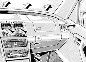
Airbags
1. Driver airbag 2. Front passenger airbag 3. Side impact airbag
The most effective occupant restraint system yet developed for use in production vehicles is the seat belt. In some cases, however, the protective effect of a seat belt can be further enhanced by an airbag. The driver airbag is located in the steering wheel hub. The passenger airbag is located in the dashboard ahead of the passenger. The side impact airbags are located in the front doors. In conjunction with wearing the seat belts with emergency tensioning retractors, the airbags can provide increased protection for the driver and passenger in certain major frontal (for front airbags) and side impacts (for side impact airbags). The operational readiness of the airbag system is verified by the indicator lamp "SRS" in the instrument cluster when turning the electronic key in steering lock to position 1 or 2. If no fault is detected, the lamp will go out after approximately 4 seconds; after the lamp goes out, the system continues to monitor the components and circuitry of the airbag system and will indicate a malfunction by coming on again. The following system components are monitored or undergo a self-check: crash-sensor(s), airbag ignition circuits, front seat belt buckles, emergency tensioning retractors, seat sensor . Initially, when the electronic key is turned from steering lock position 0 to positions 1 or 2, malfunctions in the crash-sensor are detected and indicated (the "SRS" indicator lamp stays on longer than 4 seconds or does not come on). Have the system checked at your authorized Merzedes-Benz dealer immediately. In the operational mode, after the indicator lamp has gone out following the initial check, interruptions or short circuits in the airbag ignition circuit and in the driver and passenger seat belt buckle harnesses, and low voltage in the entire system are detected and indicated.
Warning ! In the event a malfunction of the "SRS" is indicated as outlined above, the "SRS" may not be operational. For your safety, we strongly recommend that you visit an authorized Mercedes-Benz dealer immediately to have the system checked; otherwise the "SRS" may not be activated when needed in an accident, which could result in serious or fatal injury, or it might deploy unexpectedly and unnecessarily which could also result in injury.
Front Airbags The driver and passenger front "SRS" airbags are designed to activate only in certain frontal impacts. The front passenger airbag deploys only if the front passenger seat is occupied and the center console is not illuminated.
Note: Heavy objects on front passenger seat can cause the passenger front airbag to deploy in a crash.
Side Impact Airbags The side impact "SRS" airbags are designed to activate only in certain side impacts. Only the side impact airbag on the impacted side of the vehicle deploys. The side impact airbag for the front passenger deploys only if the front passenger seat is occupied. Side impact airbags operate best in conjunction with a properly positioned and fastened seat belt.
Note: Heavy objects on front passenger seat can cause the side impact airbag to deploy in a crash.
indicator lamp on the
Important ! The "SRS" airbags are designed to activate only in certain frontal (front airbags) impacts, or side (side airbags) impacts. Only during these types of impacts, if of sufficient severity to meet the deployment thresholds, will they provide their supplemental protection. The driver and passenger should always wear the seat belts, otherwise it is not possible for the airbags to provide their intended supplemental protection. In cases of other frontal impacts, angled impacts, roll-overs, other side impacts, rear collisions, or other accidents without sufficient forces, the airbag will not be activated. The driver and passengers will then be protected by the fastened seat belts. We caution you not to rely on the presence of an airbag in order to avoid wearing your seat belt. The "SRS" is designed to reduce the potential of injury in certain frontal (front airbags) impacts, and side (side impact airbags) impacts which may cause significant injuries, however, no system available today can totally eliminate injuries and fatalities. The activation of the "SRS" temporarily releases a small amount of dust from the airbags. This dust, however, is neither injurious to your health, nor does it indicate a fire in the vehicle. The service life of the airbags extends to the date indicated on the label located on the driverside door latch post. To provide continued reliability after that date, they should be inspected by an authorized Mercedes-Benz dealer at that time and replaced when necessary. Your vehicle was originally equippend with a Supplemental Restraint system (SRS). The SRS airbags are designet to activate in centrain impacts exceeding a preset treshold to reduce the potential and severity of injury.merzedes-Benz encourages you to replace deployed airbags and repair any malfunktioning airbags to ensure the vehicle will continue to provide maximum crash protections for occupants.
Warning! It is very important for your safety to always be in a properly seated position and to wear your seat belt. For maximum protection in the event of a collision always be in normal seated position with your back against the backrest. Fasten your seat belt and ensure that it is properly positioned on the body. Since the airbag inflates with considerable speed and force, a proper seating and hands on steering wheel position will help to keep you in a safe distance from the airbag: • Sit properly belted in an upright position with your back against the seat back. • Adjust the driver seat as far as possible rearward, still permitting proper operation of vehicle controls. • Do not lean with your head or chest close to the steering wheel or dashboard. • Keep hands on the outside of steering wheel rim. Placing hands and arms inside the rim can increase the risk and potential severity of hand/arm injury when the driver front airbag inflates. • Adjust the front passenger seat rearward as far as possible from the dashboard when the seat is occupied. • Children 12 years old and under must never ride in the front seat, except in a Mercedes-Benz authorized BabySmart™ compatible child seat, which operates with the BabySmart™ system installed in the vehicle to deactivate the passenger side front airbag when it is properly installed. Otherwise they will be struck by the airbag when it inflates in a crash. If this happens, serious or fatal injury will result. Failure to follow these instructions can result in severe injuries to you or other occupants.
Safety Guidelines for the Seat Belt, Emergency Tensioning Retractor and Airbag
Warning ! • Damaged belts or belts that were highly stressed in an accident must be replaced and their anchoring points must also be checked. Use only belts installed or supplied by an authorized Mercedes-Benz dealer. • Do not pass belts over sharp edges. • Do not make any modification that could change the effectiveness of the belts. • The "SRS" is designed to function on a one-time-only basis. An airbag or emergency tensioning retractor (ETR) that was activated must be replaced. • No modifications of any kind may be made to any components or wiring of the "SRS". This includes the installation of additional trim material, badges etc. over the steering wheel hub, front passenger airbag cover, or front door trim panels, and installation of additional electrical/electronic equipment on or near "SRS" components and wiring. Keep area between airbags and occupants free of objects ( e.g. packages purses, umbrellas, etc.). • An airbag system component within the steering wheel gets hot after the airbag has inflated. • Improper work on the system, including incorrect installation and removal, can lead to possible injury through an uncontrolled activation of the "SRS". • In addition, through improper work there is the risk of rendering the "SRS" inoperative. Work on the "SRS" must therefore only be performed by an authorized Mercedes-Benz dealer • When scrapping the airbag unit or emergency tensioning retractor, it is mandatory to follow our safety instructions. These instructions are available at your authorized Merzedes-Benz • Depending on the considerable deployment speed and the textile structure of the airbags, there is the possibility of light skin abrasions.
When you sell the vehicle we strongly urge you to give notice to the subsequent owner that it is equipped with an "SRS" by alerting him to the applicable section in the Owner's Manual.
Infant and Child Restraint Systems We recommend that all infants and children be properly restrained at all times while the vehicle is in motion. All lap-shoulder belts except driver seat have special seat belt retractors for secure fastening of child restraints. To fasten a child restraint, use this seat belt: Follow child restraint instructions for routing. Then pull shoulder belt out completely and let it retract. During the seat belt retraction a ratcheting sound can be heard to indicate that the special seat belt retractor is activated. The belt is now locked. Push down on child restraint to take up any slack. To deactivate, release seat belt buckle and let seat belt retract completely. The seat belt can again be used in the usual manner.
Warning ! Never release the seat belt buckle while vehicle is in motion, since the special seat belt retractor will be deactivated.
Important ! The use of infant or child restraints is required by law in all 50 states and all Canadian provinces. Infants and small children should be seated in an appropriate infant or child restraint system properly secured by a lap-shoulder belt, and that complies with U.S. Federal Motor Vehicle Safety Standard 213 and Canadian Motor Vehicle Safety Standard 213. A statement by the child restraint manufacturer of compliance with this standard can be found on the instruction label on the restraint and in the instruction manual provided with the restraint. When using any infant or child restraint system, be sure to carefully read and follow all manufacturer's instructions for installation and use. Please read and observe warning labels affixed to inside of vehicle.
Children 12 years old and under must never ride in the front seat, except in a Mercedes-Benz authorized BabySmart™ compatible child seat, which operates with the BabySmart™ system installed in the vehicle to deactivate the passenger side front airbag when it is properly installed. Otherwise they will be struck by the airbag when it inflates in a crash. If this happens, serious or fatal injury will result. According to accident statistics, children are safer when properly restrained in the rear seating positions than in the front seating positions. Infants and small children must ride in back seats and be seated in an infant or child restraint system, which is properly secured with the vehicle's seat belt, fully in accordance with the seat manufacturer's instructions. Infants and small children should never share a seat belt with another occupant. During an accident, they could be crushed between the occupant and seat belt. Children too big for child restraint systems must ride in back seats using regular seat belts. Position shoulder belt across chest and shoulder, not face or neck. A booster seat is necessary to achieve proper belt positioning for children from 41 Ibs. to the point where a lap/shoulder belt fits properly without one. When the child restraint is not in use, remove it from the car or secure it with the seat belt to prevent the child restraint from becoming a projectile in the event of an accident.
U.S.A. Models only: Since 1986 all U.S. child restraints comply with U.S. regulations without the use of a tether strap. Canada Models only: This vehicle is provided with tether anchorages for a top tether strap. Consult your authorized Mercedes-Benz dealer for installation of these anchorages. In compliance with Canadian Motor Vehicle Safety Standard 210.1, child restraint tether anchorage hardware is attached to the tool kit located in the trunk.
Enlarged Cargo (Option)
1. Locking handle, left backrest 2. Locking handle, right backrest
3. Indicator, right backrest lock, visible in unlocked position 4. Indicator, left backrest lock, not visible in locked position
Split Folding Rear Seat Backrest
On vehicles with optional split folding rear seat backrest you can fold down the two sections separately to enlarge the cargo area.
Fold down: Pull locking handle and fold backrest forward. Set up: Pull backrest up until it locks in its upright position. Check for secure locking by pushing and pulling on the backrest.
Warning ! Always lock backrest in its upright position when rear seat bench is occupied by passengers, cargo is being carried in the trunk, or the extended cargo area is not in use.
Note: To prevent unauthorized persons from access to the trunk, always lock backrest in its upright position.
Loading instructions (Vehicles with enlarged cargo area)
The total load weight including vehicle occupants and luggage/ cargo should not exceed the vehicle capacity weight indicated on the certification tag which can be found on the left door pillar. The handling characteristics of a fully loaded vehicle depend greatly on the load distribution. It is therefore recommended to load the vehicle according to the illustrations shown, with the heaviest items being placed towards the front of the vehicle. Always place items being carried against front or rear seat backrests, and fasten them as securely as possible. The heaviest portion of the cargo should always be kept as low as possible since it influences the handling characteristics of the vehicle.
Notes: The trunk is the preferred place to carry objects. The enlarged cargo area should only be used for items which do not fit in the trunk alone.
Warning ! In an accident, during hard braking or sudden maneuvers, loose items will be thrown around inside the vehicle, and can cause injury to vehicle occupants unless the items are securely fastened in the vehicle. To help avoid personal injury during a collision or sudden maneuver, exercise care when stowing things. Put luggage or cargo in the trunk if possible. Do not pile luggage or cargo higher than the seat backs. Do not place anything on the shelf below the rear window. Never drive vehicle with trunk lid open while pass-through is not closed and seat backrest sections not locked in its upright position. Deadly carbon monoxide (CO) gases may enter vehicle interior resulting in unconsciousness and death.
Cargo Tie-Down Rings (Vehicles with enlarged cargo area)
1. Ring Carefully secure cargo by applying even load on all four rings with rope of sufficient strength to hold down the cargo.
Shelf below Rear Window
Warning! The shelf below the rear window should not be used to carry objects. This will avoid such objects from being thrown about and injuring vehicle occupants during an accident or sudden maneuver. The trunk is the preferred place to carry objects.
Steering Lock
0 - The electronic key can be withdrawn in this position only. The steering is locked with the electronic key removed from the steering lock. The electronic key an be removed only with the selector lever in position "P" and the foot off the brake pedal. After removing the electronic key or with the electronic key in steering lock position 0, the selector lever is locked in position "P". 1 - Steering is unlocked. (If necessary, move steering wheel slightly to allow the electronic key to be turned clockwise to position 1.) Most electrical consumers can be operated. For detailed information see respective subjects. 2 - Driving position. 3 - Starting position.
Refer to Index for Starting and turning off the engine.
Warning ! When leaving the vehicle always remove the electronic key from the steering lock, and lock the vehicle. Do not leave children unattended in the vehicle, or with access to an unlocked vehicle. Unsupervised use of vehicle equipment may cause serious personal injury.
Important ! If the electronic key is left in the steering lock position 0 for an extended period of time, it can no longer be turned in the lock. In this case, remove electronic key from steering lock and reinsert.
Notes: A warning sounds when the driver's door is opened with the electronic key in steering lock position 1 or 0. With the engine at idle speed, the charging rate of the alternator (output) is limited. It is therefore recommended to turn off unnecessary electrical consumers while driving in stop-and-go traffic. This precaution helps to avoid draining of the battery. Unnecessary strain on the battery and charging system may be minimized by turning off the following power consumers, for example: Heated seats, rear window defroster. In addition, the automatic climate air volume control should be set to the lowest position. The steering lock can only be unlocked with the vehicle battery properly connected.
Caution ! To prevent accelerated battery discharge and a possible dead battery, always remove the electronic key from the steering lock. Do not leave the electronic key in steering lock position 0.
Combination Switch
1. Low beam (exterior lamp switch position 2. High beam (exterior lamp switch position 3. High beam flasher (high beam available independent of exterior lamp switch position) 4. Turn signals, right 5. Turn signals, left To signal minor directional changes, such as changing lanes on a highway, move combination switch to the point of resistance only and hold it there. To operate the turn signals continuously, move the combination switch past the point of resistance (up or down). The switch is automatically cancelled when the steering wheel is turned to a large enough degree.
6 Control for windshield wiper/washer system: Push briefly for a single wipe without adding washer fluid (use only when windshield is wet) Push past detent point: • windshield washer system ). • optional headlamp cleaning system (only in exterior lamp positions When the washer system is activated, the wipers also operate for a limited time. 7 Windshield wiper 0 Wiper off I Intermittent wiping (optional rain sensor: One initial wipe, pauses between wipes are automatically controlled by a rain sensor monitoring the wetness of the windshield.) II Normal wiper speed III Fast wiper speed
Note: The windshield washer reservoir, hoses and nozzles are automatically heated.
or
Windshield Washer Fluid Mixing Ratio For temperatures above freezing: MB Windshield Washer Concentrate "S" and water 1 part "S" to 100 parts water (40 ml "S" to 1 gallon water). For temperature below freezing: MB Windshield Washer Concentrate "S" and commercially available premixed windshield washer solvent/antifreeze 1 part "S" to 100 parts solvent (40 ml "S" to 1 gallon solvent).
Windshield Wiper Smears If the windshield wiper smears the windshield, even during rain, activate the washer system as often as necessary. The fluid in the washer reservoir should be mixed in the correct ratio.
Blocked Windshield Wiper If the windshield wiper becomes blocked (for example, due to snow), switch off the wiper. For safety reasons before removing ice or snow, remove electronic key from steering lock. Remove blockage. Activate combination switch again (electronic key in steering lock position 1).
Turn Signal Failure If one of the turn signals fails, the turn signal indicator system flashes and sounds at a faster than normal rate.
Exterior Lamp Switch
Off Parking lamps (also side marker lamps, taillamps, license plate lamps, instrument panel lamps) Canada only: When the engine is running, the low beam is additionally switched on. Parking lamps plus low beam or high beam headlamps (combination switch pushed forward). Standing lamps, right (turn left one stop). Standing lamps, left (turn left two stops). Front fog lamps (pull out one stop) with parking lamps and/or low beam headlamps on. Rear fog lamp (pull out to 2nd detent) in addition to fog lamps. Yellow indicator lamp in lamp switch
comes on.
Standing Lamps When the vehicle is parked on the street the standing lamps (right or left side parking lamps) can be turned on, making the vehicle more visible to passing vehicles The standing lamps cannot be operated with the electronic key in steering lock position 2.
Note: With the electronic key removed and a front door open, a warning sounds if the vehicle's exterior lamps (except standing lamps) are not switched off. Fog lamps will operate with the parking lamps and the low or high beam headlamps Fog lamps should only be used in conjunction with low beam headlamps Consult your State or Province Motor Vehicle Regulations regarding allowable lamp operation. Fog lamps are automatically switched off when the exterior lamp switch is turned to position
Daytime Running Lamps Canada only
When the engine is running and the selector lever is in a driving position, the low beam (includes parking lamps, side marker lamps, taillamps and license plate lamps) are automatically switched on. When shifting from a driving position to position "N" or "P", the low beam switches off (2 seconds delay).
For nighttime driving the exterior lamp switch should be turned to position headlamps.
to permit activation of the high beam
Night Security Illumination
When exiting the vehicle after driving with the exterior lamps on, they switch on again for added illumination for approximately 30 seconds after closing the last door. The lamp-on time period can be changed at your Mercedes-Benz dealer.
Inside Rear View Mirror Manually adjust the mirror. Use your inside mirror to determine the size and distance of objects seen in the passenger side convex mirror.
Antiglare Night Position With the electronic key in steering lock position 2, the mirror reflection brightness responds to changes in light sensitivity. With gear selector lever in position "R", or with the interior lamp switched on, the mirror brightness does not respond to changes in light sensitivity.
Note: The automatic antiglare function is restricted, if incoming light is not aimed directly at sensors in the mirror.
Exterior Rear View Mirrors
The switch is located on the center console. Turn electronic key in steering lock to position 2. First select the mirror to be adjusted - press button:
Left mirror Right mirror
To adjust, toggle the switch forward, backward or to either side. With the electronic key in steering lock position 2, the driver's side mirror reflection brightness responds to changes in light sensitivity. With gear selector lever in position "R", or with the interior lamp switched on, the driver's side mirror brightness does not respond to changes in light sensitivity.
Warning ! Exercise care when using the passenger-side mirror. The passenger-side exterior mirror is convex (outwardly curved surface for a wider field of view). Objects in mirror are closer than they appear. Check your inside rear view mirror or glance over your shoulder before changing lanes.
Notes: The exterior mirrors have electrically heated glass. The heater switches on automatically, depending on outside temperature. If an exterior mirror housing is forcibly pivoted from its normal position, it must be repositioned by applying firm pressure until it snaps into place.
Ashtrays Center Console, Front
To remove ashtray: Push sliding knob (1) toward the right to eject the insert. To install ashtray: Install insert into ashtray frame and push down to engage.
By touching the top of the cover lightly, the ashtray opens automatically. Prior to removing the ashtray insert, move the gear selector lever to position "N".
Warning! Remove front ashtray only with vehicle standing still. With the gear selector lever in position "N", turn off the engine and set the parking brake. Otherwise the vehicle might move as a result of unintended contact with the gear selector lever.
Center Console, Rear
To remove ashtray: Push center bar down and pull out the ashtray. To install ashtray: Install bottom of ashtray, push center bar down, and close ashtray.
Lighter
Turn electronic key in steering lock to position 1 or 2. Push in lighter (1); it will pop out automatically when hot.
Warning ! Never touch the heating element or sides of the lighter, they are extremely hot, hold at knob only.
Note: The lighter socket can be used to accommodate electrical accessories up to maximum 85 W
Sun Visors
Swing sun visors down to protect against sun glare. If sunlight enters through a side window, disengage visor from inner mounting and pivot to the side.
Illuminated Vanity Mirrors With the visor engaged in its inner mounting, the lamp can be switched on by opening the cover.
Warning ! Do not use the vanity mirror while driving.
The lamp goes out automatically after approximately 5 minutes.
Interior Lighting
1. Door contact switch: Press once and interior lamps are switched on when opening a door. Interior lamps are switched on, and off (soft fade) delayed, when unlocking or locking the vehicle, or when opening or closing a door. However, there will be no (soft fade) delay when the electronic key is in steering lock position 2 Press again and interior lamps remain switched off, even when centrally unlocking or opening a door. 2. Press to switch interior and reading lamps on or off. 3. Press to switch rear passenger compartment lamp on or off. 4. Press to switch reading lamp on or off.
Parcel Net in Front Passenger Footwell A small convenience parcel net is located in the front passenger footwell. It is for small and light items, such as road maps, mail, etc..
Warning ! Do not place heavy or fragile objects, or objects having sharp edges, in the parcel net. In an accident, during hard braking or sudden maneuvers, they could be thrown around inside the vehicle, and cause injury to vehicle occupants.
Storage Compartments and Cupholder
Glove Box 1. Unlocking: Turn mechanical key to vertical position and remove. 2. Locking: Turn mechanical key to the right and remove. 3. Opening: Pull on handle.
Caution ! Keep compartment lids closed. This will prevent stored objects from being thrown about and injuring vehicle occupants during an accident and sudden maneuvres.
Storage Compartments in Center Console To open compartment in armrest: Lift lid with handle (4). To open compartment under armrest: Lift lid with handle (5). To close: Lower lid until it engages in lock.
Cupholder in Center Console To open cover: Touch top of cover (6) slightly. The cover opens automatically.
To open cup holder: Briefly press button (7). The cup holder opens automatically. To store cup holder: Push button (7) down until cup holder engages. Close cover (6).
Caution ! Keep cup holder closed while travelling. Place only containers that fit into the cup holder to prevent spills. Do not fill containers to a height where the contents could spill during vehicle maneuvers, especially hot liquids.
Sliding/Pop-Up Roof (optional)
1. to slide roof open 2. to slide roof closed 3. to raise roof at rear 4. to lower roof at rear
Turn electronic key in steering lock to position 1 or 2. The switch is illuminated when the exterior lamps are switched on (except standing lamps). With the roof closed or tilted open, a screen can be slid into the roof opening to guard against sun rays. When sliding the roof open, the screen will also retract.
Warning ! When closing the sliding/ pop-up roof, be sure that there is no clanger of anyone being harmed by the closing procedure. The closing procedure can be immediately reversed by either moving the switch in direction (1) or (3), turning the mechanical key to the unlocking position, or pressing button and holding it.
on the remote control,
Notes: The sliding/pop-up roof can be opened or closed manually should an electrical malfunction occur, refer to Sliding/Pop-Up Roof, Emergency Operation in Index. The sliding/pop-up roof can also be closed with the mechanical key or infrared remote control while locking the vehicle doors or trunk (see Central Locking System in Index).
Synchronizing Sliding/Pop-Up Roof If the power supply was interrupted (battery disconnected or empty), or if the sliding/pop-up roof is blocked during closing/opening procedure, the system has to be synchronized. To do so, turn electronic key in steering lock to position 2, move and hold switch in direction (3) until the sliding/pop-up roof is completely raised at rear, and hold for additional 1 second.
Power Windows
on center console, front
Switches for:
1. left, front 2. left, rear 3. right, front 4. right, rear 5. switch for rear door window override 6. individual switches (rear doors) in rear doors
in rear doors
Turn electronic key in steering lock to position 1 or 2. Press switch in to resistance point:
to open to close
or
or
becomes visible.
past resistance point and release - window opens or closes completely. To interrupt
Release switch when window is in desired position.
Express Opening and Closing
Press switch If the upward movement of the window is blocked during the closing procedure, procedure, briefly press the window will stop during the last few inches before closure and open slightly. When pressing and holding the to close the window, and upward movement of the window is blocked during the last few inches before switch closure, it will stop but not open slightly.
Blocking of Rear Door Window Operation If no operation of the rear windows by switch (6) located in rear doors (for instance by children) is desired, slide override switch (5) to right, symbol
Warning ! When closing the windows, be sure that there is no danger of anyone being harmed by the closing procedure. In case of obstruction, the automatic reversal will not operate if a window is being closed by pressing the switch to its resistance point and holding it there, or when using a mechanical key or the remote control.The closing procedure can be immediately reversed by either pressing the switch turning the mechanical key to the unlocking position, or pressing button and holding it.
Note: The power windows can also be closed with the mechanical key or infrared remote control while locking the vehicle doors or trunk (see Central Locking System in Index).
Warning ! When leaving the vehicle, always remove the electronic key from the steering lock, and lock the vehicle. Do not leave children unattended in the vehicle, or with access to an unlocked vehicle. Unsupervised use of vehicle equipment can cause serious personal injury.
Synchronizing Power Windows If the power supply was interrupted (battery disconnected or empty), the windows cannot be opened or closed by the Express feature. To resynchronize the Express feature, press window is completely closed and hold for additional 2 seconds. Repeat procedure for each window. The automatic full opening and closing procedure of the windows should now be restored.
side of power window switch until the
on the remote control,
Instrument Lamps Press + or - button to vary intensity of instrument lamps.
Display illumination The display for temperature, odometer, oil level indicator, FSS indicator and clock is illuminated briefly when opening the driver door. The display illumination brightness responds automatically according to changes in the surrounding light sensitivity. To briefly illuminate the display (with electronic key removed or in steering lock position 0 or 1), pressbutton O, +,- , h or m.
Trip Odometer • To reset: • Press button O once and hold (with display illuminated). • Press button O twice and hold (with display not illuminated).
Clock Adjusting clock (display illuminated): Press button m or h briefly. The display flashes to indicate that the clock can be adjusted. Minute: Press button m briefly. Minutes: Press and hold button m. Hour: Press button h briefly. Hours: Press and hold button h .
Trunk Lid Release Switch
The switch is located on the center console. A minimum height clearance of 5.9 ft (1.8 m) is required to open the trunk lid. To open the trunk, the vehicle must be parked and unlocked. Pull up on switch until trunk lid is open. The indicator lamp remains on with trunk lid open.
Notes: With vehicle centrally locked, the trunk can also be opened by using the remote control. Press button. The trunk lid cannot be opened by the switch when previously locked separately with the mechanical key. To open, refer to Trunk, separately locked (in Index).
Garage Door Opener
1. Integrated remote control transmitter 2. Portable remote control transmitter
Warning ! When programming a garage door opener, the door moves up or down. When programming or operating the remote control make sure there is no possibility of anyone being harmed by the moving door.
The built-in remote control is capable of operating up to three separately controlled objects.
Notes: Certain types of garage door openers are incompatible with the integrated opener. If you should experience difficulties with programming the transmitter, contact your authorized Mercedes-Benz dealer or call Mercedes-Benz Customer Assistance Center (in the U.S.A. only) at 1-800-FOR-MERCedes. For operation in the USA only: This devise complies with Part 15 of the FCC Rules. Operation is subject to the following two conditions: (1) This device may not cause harmful interference, and (2) this device must accept any interference received, including interference that may cause undesired operation. Any unauthorized modification to this device could void the user's authority to operate the equipment.
Programming or reprogramming the integrated remote control: 1. Turn electronic key in steering lock to position 1 or 2. 2. Press and hold one button of the integrated remote control located on the sun visor until its control light begins to flash at a rate of about once a second. Continue holding down the button. Note: The light blinks immediately if the integrated remote control is being programmed for the first time, or if its memory was previously erased. If you are reprogramming a previously used button, the light will flash after about 20 seconds. 3. Aim portable remote control transmitter at the integrated remote control transmitter to be programmed. While still holding down the button on the transmitter on the inside rear view mirror, press down the button on you r portable remote control transmitter, until the integrated remote control light starts to flash rapidly. This means that the integrated transmitter has accepted the frequency and code of the portable transmitter. 4. If you wish, repeat the procedure for each remaining button.
Note: If the garage door opener is equipped with the "rolling code feature", it needs to be trained to accept the remote control command. To do so, the assistance of a second person is required.
1. Locate training button (part of the opener unit in the garage). 2. Press and hold training button until training light next to the button begins to flash (in two seconds). 3. Now have the second person press and hold the previously programmed button on the integrated remote control transmitter until the training light on the garage door opener is lit continuously (in two seconds). 4. Release and press the programmed button on the integrated remote control transmitter once again to turn off the training light in the garage door opener. 5. Confirm the garage door operation by pressing the programmed button on the integrated remote control transmitter.
Operation of remote control: 1. Turn electronic key in steering lock to position 1 or 2. 2. Select and press the appropriate button to activate the remote controlled device. The integrated remote control transmitter continues to send the signal as long as the button is pressed - up to 20 seconds.
Erasing the integrated remote control memory: 1. Turn electronic key in steering lock to position 1 or 2. 2. Simultaneously holding down _ left and right side buttons for approximately 20 seconds, or until the control light blinks rapidly, will erase the codes of all three channels.
Cellular Telephone
The vehicle is prepared for the installation of a cellular telephone. For further information and installation contact your authorized Mercedes-Benz dealer.
Warning ! Some jurisdictions prohibit the driver from using a cellular telephone while driving a vehicle. Whether or not prohibited by law, for safety reasons, the driver should not use the cellular telephone while the vehicle is in motion. Stop the vehicle in a safe location before answering or placing a call.
Drinking and Driving
Warning ! Drinking and driving can be a very dangerous combination. Even a small amount of alcohol or drugs can affect your reflexes, perceptions and judgement. The possibility of a serious or even fatal accident is sharply increased when you drink and drive. Please don't drink and drive or allow anyone to drive after drinking.
Parking Brake To engage, firmly depress parking brake pedal. When the electronic key is in steering lock position 2, the brake warning lamp in the instrument cluster should come on brightly. To release the parking brake, pull handle on instrument panel. The brake warning lamp in the instrument cluster should go out. A warning sounds, if you start to drive without having released the parking brake. Also see Brake Warning Lamp Test in Index.
Driving Off Apply the service brakes to test them briefly after driving off. Perform this procedure only when the road is clear of other traffic. Warm up the engine smoothly. Do not place full load on the engine until the operating temperature has been reached. When starting off on a slippery surface, do not allow one drive wheel to spin for an extended period with the ASR or ESP switched off. Doing so may cause serious damage to the drive train which is not covered by the Mercedes - Benz Limited Warranty.
Warning ! Keep driver's foot area clear at all times. Objects stored in this area may impair pedal movement.
Automatic Transmission
The automatic transmission selects individual gears automatically, dependent upon • Selector lever position • Program mode selector • Accelerator position • Vehicle speed
The gear shifting is process is continuously adapted, dependent on the driving style, the driving situation and the road characteristics.
Important ! When parking the car or before working on the vehicle with the engine running, firmly depress the parking brake pedal and shift the selector lever into "P".
Driving The selector lever is automatically locked while in position "P". To move the selector lever out of position "P", the service brake pedal must be firmly depressed before the shift lock will release. Shift selector leverto the desired position only when the engine is idling normally and the service brake is applied. Do not release the brake until ready to drive. The vehicle may otherwise start creeping when the selector lever is in drive or reverse position.
Warning ! It is dangerous to shift the selector lever out of "P" or "N" if the engine speed is higher than idle speed. If your foot is not firmly on the brake pedal, the car could accelerate quickly forward or in reverse. You could lose control of the car and hit someone or something. Only shift into gear when the engine is idling normally and when your right foot is firmly on the brake pedal.
Important ! After selecting any driving position from "N" or "P", wait a moment to allow the gear to fully engage before accelerating, especially when the engine is cold.
Accelerator Position Partial throttle = early upshifting = normal acceleration Full throttle = later upshifting = rapid acceleration Kickdown (depressing the accelerator beyond full throttle) = downshifting to a lower gear maximum acceleration. Once the desired speed is attained, ease up on the accelerator - the transmission shifts up again.
Selector Lever Positions The automatic gear shifting process can be adapted to specific operating conditions using the selector lever. P - Parking position. The parking position is to be used when parking the vehicle. Engage only with the car stopped. The parking position is not intended to serve as a brake when the vehicle is parked. Rather, the driver should always use the parking brake in addition to placing the selector lever in park to secure the vehicle.
Note: The electronic key can be removed from the steering lock only with the foot off the brake pedal and the selector lever in position "P". With the electronic key removed, the selector lever is locked in position "P".
R - Reverse gear. Shift to reverse gear only with the car stopped. N - Neutral. No power is transmitted from the engine to the rear axle. When the brakes are released, the vehicle can be moved freely (pushed or towed). Do not engage "N" while driving except to coast when the vehicle is in danger of skidding (e.g. on icy roads, see Winter driving Instructions in Index).
Important ! Coasting the vehicle, or driving for any other reason with selector lever in "N" can result in transmission damage that is not covered by the Mercedes-Benz Limited Warranty.
D - The transmission automatically upshifts through 5th gear. Position "D" provides optimum driving characteristics under all normal operating conditions. 4 - Upshift through 4th gear only. Suitable for performance driving. To shift from position "D" to "4", push selector lever to the left. 3 - Upshift through 3rd gear only. Suitable for moderately steep hills. Since the transmission does not shift higher than 3rd gear, this gear selection will allow use of the engine's braking power downhill. 2 - Upshift through 2nd gear only. For driving in mountainous regions or under extreme operating conditions. This gear selection will allow use of the engine's braking power when descending steep grades. 1 - In this position, the engine's braking effect is utilized by shifting into 1st gear. Use this position while descending very steep or lengthy downgrades and only at speeds below 40 mph (60 km/h).
Important ! With selector lever in position "D", "4" or "3", upshifting from 1st to 2nd to 3rd gear is delayed depending on vehicle speed and engine temperature. This allows the catalytic converter to heat up more quickly to operating temperatures. During the brief warm-up period this delayed upshift and increased engine noise might be perceived as a malfunction. However, neither the engine nor transmission are negatively affected by this mode of operation. The delayed upshift is effective with vehicle speeds below 31 mph (50 km/h) at partial throttle and engine temperatures below 95°F (35°C). To avoid overrevving the engine when the selector lever is moved to a lower driving range, the transmission will not shift to a lower gear, if the engine's speed limit would be exceeded. In this case there will be no downshift, even when the vehicle speed reaches the engine's speed limit of that gear, e.g. by applying the service brakes. Continue driving in the usual manner. The transmission will then shift down automatically. To prevent the engine from laboring at low RPM when driving uphill gradients or with your vehicle heavily loaded, the automatic transmission will downshift when necessary to maintain engine RPM within the best torque range.
Warning! On slippery road surfaces, never downshift in order to obtain braking action. This could result in drive wheel slip and reduced vehicle control. Your vehicle's ABS will not prevent this type of loss of control.
Warning ! On slippery road surfaces, never downshift in order to obtain braking action. This could result in rear wheel slip and reduced vehicle control. Your vehicle's ABS will not prevent this type of loss of control.
Maneuvering To maneuver in tight areas, e.g. when pulling into a parking space, control the vehicle speed by gradually releasing the brakes. Accelerate gently and never abruptly step on the accelerator. To rock a vehicle out of soft ground (mud or snow), alternately shift from forward to reverse, while applying slight partial throttle. Rocking a vehicle free in this manner may cause the ABS malfunction indicator lamp to come on. Turn off and restart the engine to clear the malfunction indication.
Stopping For brief stops, e.g. at traffic lights, leave the transmission in gear and hold vehicle with the service brake. For longer stops with the engine idling, shift into "N" or "P" and hold the vehicle with the service brake. When stopping the vehicle on an uphill gradient, do not hold it with the accelerator, use the brake. This avoids unnecessary transmission heat build up.
Warning ! Getting out of your vehicle with the selector lever not fully engaged in position "P" is dangerous. Also, when parked on an incline, position "P" alone may not prevent your vehicle from moving, possibly hitting people or objects. Always set the parking brake in addition to shifting to position "P". When parked on an incline, also turn front wheel against curb.
Program Mode Selector Switch The transmission is provided with a selector switch for Standard "S" and Winter/Wet (snow and ice) "W" program modes.
Important ! Always be certain of the program mode selected since the vehicle driving characteristics change with the selection of the program mode.
S - Standard mode Press switch on symbol "S". Use this mode for all regular driving. The vehicle starts out in 1st gear. Accelerator Operation: Fast on = depressing the accelerator pedal quickly (not into kickdown position) while driving continuously, rather than depressing the accelerator pedal in the usual manner, will cause the automatic transmission to shift down into a lower gear. This gear shifting process is dependent on the current vehicle speed. Fast off = there will be no upshift when releasing the accelerator pedal quickly, e.g. using the engine's braking power during performance driving
W - Winter/Wet (snow and ice) mode Press switch on symbol "W". The vehicle starts out in 2nd gear, except with selector lever in 1st gear, or with accelerator pedal in kick-down position. The "W" mode helps to improve traction and driving stability of the vehicle. The gear shifting process occurs at lower vehicle and engine speeds than in the "S,' program mode.
Important Dependent on the program mode selector switch position "S" or "W" and the gear selector lever in position "13", the ratio of power transmission changes.
Emergency Operation (Limp Home Mode) If vehicle acceleration worsens, or the transmission no longer shifts, the transmission is most likely operating in Limp Home Mode which engages when there is a malfunction at the transmission. This condition may be accompanied by the "CHECK ENGINE" malfunction indicator lamp in the instrument cluster coming on. In this mode only the 2nd gear or reverse gear can be activated.
To engage 2nd gear or reverse: 1. Stop the vehicle. 2. Move selector lever to position "P". 3. Turn off the engine. 4. Wait 10 seconds. 5. Restart the engine. 6. Move selector lever to position "D" (for 2nd gear), or move selector lever to position "R" (for reverse gear).
Have the transmission checked at your authorized Mercedes-Benz dealer as soon as possible.
Cruise Control
Cruise Control Any given speed above approximately 25 mph (40 km/h) can be maintained with the cruise control by operating the lever. 1. Accelerate and set: Lift lever briefly to set speed. Hold lever up to accelerate. 2. Decelerate and set: Depress lever briefly to set speed. Hold lever down to decelerate. Normally the vehicle is accelerated to the desired speed with the accelerator. Speed is set by briefly pushing the lever to position 1 or 2. The accelerator can be released. The speed can be increased (e.g. for passing) by using the accelerator. After the accelerator is released, the previously set speed will be resumed automatically. If a set speed is to be increased or decreased slightly, e.g. to adapt to the traffic flow, hold lever in position 1 or 2 until the desired speed is reached, or briefly tip the lever in the appropriate direction for increases or decreases in 0.6 mph (1 km/h) increments. When the lever is released, the newly set speed remains. 3. Cancelling To cancel the cruise control, briefly push lever to position 3. When you step on the brake pedal or the vehicle speed drops below approx. 25 mph (40 km/h), for example when driving upgrade, the cruise control will be cancelled. If the cruise control cancels by itself and remains inoperative until the engine is restarted, have the system checked at your authorized Mercedes-Benz dealer as soon as possible. 4. Resume If the lever is briefly pushed to position 4 when driving at a speed exceeding approx. 25 mph (40 km/h), the vehicle resumes the speed which was set prior to the cancellation of the cruise control. The last memorized speed is cancelled when the electronic key in the steering lock is turned to position 1 or 0.
Note: If the engine does not brake the vehicle sufficiently while driving on a downgrade, the speed you set on the cruise control may be exceeded. In this case the automatic transmission shifts down (max. to 3rd gear) to maintain the set cruise control speed by using the engine's braking power. As soon as the grade eases, the automatic transmission shifts up again dependent on the selector lever position. Nevertheless, in some cases you may have to step on the brake pedal to slow down. In this case the cruise control is switched off. Use the lever to resume the previously set speed.
Caution ! Moving gear selector lever to position "N" switches the cruise control off.
Warning ! Only use the cruise control if the traffic and weather conditions make it advisable to travel at a steady speed. • The use of cruise control can be dangerous on winding roads or in heavy traffic because conditions do not allow safe driving at a steady speed. • The use of cruise control can be dangerous on slippery roads. Rapid changes in tire adhesion can result in wheel spin and loss of control. The "Resume" function should only be operated if the driver is fully aware of the previously set speed and wishes to resume this particular preset speed.
Charge Indicator Lamp Should the charge indicator lamp fail to come on prior to starting when the electronic key is in steering lock position 2 or should it fail to go out after starting or during operation, this indicates a fault which must be repaired at an authorized Mercedes-Benz dealer immediately. If the charge indicator lamp comes on while the engine is running, this may indicate that the poly-V-belt has broken. Should this condition occur, the poly-V-belt must be replaced before continuing to operate the vehicle. Otherwise, the engine will overheat due to an inoperative water pump which may result in damage to the engine. Do not continue to drive the vehicle with the charge indicator lamp illuminated. Doing so could result in serious engine damage that is not covered by the Mercedes-Benz Limited Warranty.
Low Engine Oil Level Warning Lamp With the electronic key in steering lock position 2, the oil level warning lamp comes on. It should go out immediately when the engine is running. If the warning lamp does not go out after starting the engine, or comes on with the engine running and at operating temperature, the engine oil level has dropped to approximately the minimum mark on the dipstick. When this occurs, the warning lamp will first come on intermittently and then stay on if the oil level drops further. If no oil leaks are noted, continue to drive to the nearest service station where the engine oil should be topped to the "full" mark on the dipstick with an approved oil. The low engine oil level warning light should not be ignored. Extended driving with the light illuminated could result in serious engine damage that is not covered by the Mercedes-Benz Limited Warranty. In addition to the warning lamp, the engine oil level should be periodically checked with the dipstick (or via the odometer display - Model C280 and C43 AMG only), for example during a fuel stop, or before a long trip (see Engine Oil Level, Checking in Index)
Engine Oil Consumption Engine oil consumption checks should only be made after the break-in period. During the breaking period, higher oil consumption may be noticed and is normal. Frequent driving at high engine speeds results in increased consumption.
Fuel Reserve and Fuel Cap Placement Warning Lamp With the electronic key in steering lock position 2, the fuel reserve warning lamp comes on. It should go out immediately when the engine is running. If the warning lamp does not go out after starting the engine, or if it comes on while driving, it indicates that the fuel level is down to the reserve quantity of approximately 2.1 gal (8 liters). The warning lamp blinks when the fuel cap is not closed, or a fuel system leak has been detected. Retighten cap and see if lamp goes out. If the warning lamp continues to blink after closing the fuel cap correctly, have the fuel system checked at your authorized Mercedes-Benz dealer as soon as possible. Leaving the engine running and the fuel cap open can cause the "Check Engine" lamp to illuminate).
Tachometer Red marking on tachometer: Excessive engine speed. Avoid this engine speed, as it may result in serious engine damage that is not covered by the Mercedes-Benz Limited Warranty. For engine protection, the fuel supply is interrupted if the engine is operated within the red marking.
Seat Belt Warning Lamp With the electronic key in steering lock position 2, the warning lamp comes on, and a warning sounds for a short time if the drivers seat belt is not fastened. After starting the engine, the warning lamp blinks for a brief period to remind the driver and passengers to fasten seat belts.
Outside Temperature Indicator The temperature sensor is located in the front bumper area. Due to its location, the sensor can be affected by road or engine heat during idling or slow driving. This means that the accuracy of the displayed temperature can only be verified by comparison to a thermometer placed next, to the sensor, not by comparison to external displays (e.g. bank signs etc.). Adaptation to ambient temperature takes place in steps and depends on the prevailing driving conditions (stop-and- go or moderate, constant driving) and amount of temperature change.
Warning ! The outside temperature indicator is not designed to serve as an Ice-Warning Device and is therefore unsuitable for that purpose. Indicated temperatures just above the freezing point do not guarantee that the road surface is free of ice.
Coolant Temperature Gauge If the antifreeze mixture is effective to -22°F (-30°C), the boiling point of the coolant in the pressurized cooling system of your vehicle is approx. 266°F (130°C). During severe operating conditions and stop-and-go city traffic, the coolant temperature may rise close to the red marking. The engine should not be operated with the coolant temperature in the red zone. Doing so may cause serious engine damage which is not covered by the Mercedes-Benz Limited Warranty.
Warning ! • Driving when your engine is badly overheated can cause some fluids which may have leaked into the engine compartment to catch fire. You could be seriously burned. • Steam from an overheated engine can cause serious burns and can occur just by opening the engine hood. Stay away from the engine if you see or hear steam coming from it.
Turn off the engine, get out of the vehicle and do not stand near the car until it cools down.
Low Engine Coolant Level Warning Lamp With the electronic key in steering lock position 2, the warning lamp comes on. It should go out when the engine is running. If the warning lamp does not go out after starting the engine, or if it comes on while driving, then the coolant level has dropped below the required level. If no leaks are noticeable and the engine temperature does not increase, continue to drive to the nearest service station and have coolant added to the coolant system (see Index). The low engine coolant level warning light should not be ignored. Extended driving with the light illuminated may cause serious engine damage not covered by the Mercedes-Benz Limited Warranty. In cases of major or frequent minor coolant loss, have the cooling system checked at your authorized Mercedes-Benz dealer as soon as possible.
Note: Do not drive without coolant in the cooling system. The engine will overheat causing major engine damage. Monitor the coolant temperature gauge while driving.
Warning ! Do not spill antifreeze on hot engine parts. Antifreeze contains ethylene glycol which may burn if it comes into contact with hot engine parts. You can be seriously burned.
Low Windshield and Headlamp Washer System Fluid Level Warning Lamp With the electronic key in steering lock position 2, the warning lamp comes on. It should go out when the engine is running. If the warning lamp does not go out after starting the engine, or if it comes on while driving, the level of the reservoir has dropped to approx.1/4 of the total volume. The reservoir should be refilled with MB Windshield Washer Concentrate "S" and water (or commercially available premixed windshield washer solvent/antifreeze, depending on ambient temperature - see Index) at the next opportunity. The reservoir for the windshield and headlamp washer systems is located in the engine compartment.
Exterior Lamp Failure indicator Lamp With the electronic key in steering lock position 2, an exterior lamp comes on. It should go out when the engine is running. If the warning lamp does not go out after starting the engine, or if it comes on while driving, this lamp indicates a failure in the parking lamp, taillamp, stop lamp, or low beam headlamp. If an exterior lamp fails, the indicator lamp will come on only when that lamp is switched on. If a brake lamp fails, the lamp failure indicator will come on when applying the brake and stay on until the engine is turned off.
Note: If additional lighting equipment is installed (e.g. auxiliary headlamps etc.) be certain to connect into the fuse before the failure indicator monitoring unit in order to avoid damaging the system.
Brake Pad Wear Indicator Lamp With the electronic key in steering lock position 2, the brake pad wear indicator lamp comes on . It goes out when the engine is running. If the indicator lamp lights up during braking, this indicates that the brake pads are worn down. Have the brake system checked at your authorized Mercedes-Benz dealer as soon as possible.
Brake Warning Lamp With the electronic key in steering lock position 2, the brake warning lamp will come on. It should go out when the engine is running. The brake warning lamp will come on: • when there is insufficient brake fluid in the reservoir (engine running and parking brake released), or • when the parking brake is set (engine running).
Warning ! Driving with the brake warning lamp illuminated can result in an accident. Have your brake system checked immediately if the brake warning lamp stays on. Don't add brake fluid before checking the brake system. Overfilling the brake fluid reservoir can result in spilling brake fluid on hot engine parts and the brake fluid catching fire. You can be seriously burned.
If you find that the minimum mark on the brake fluid reservoir is reached, have the brake system checked for brake pad thickness and leaks. To test the brake warning lamp, turn electronic key in steering lock to position 2. The brake warning lamp comes on, and should go out when the engine is running.
Flexible Service System (FSS)
or
or
or distance
appears in the main odometer field prior to the next suggested service. Depending on operating
The FSS permits a flexible service schedule that is directly related to the operating conditions of the vehicle. The symbol remaining. conditions throughout the year, the next service is calculated and displayed in days The message is displayed for approx. 10 seconds when turning the electronic key in steering lock to position 2, or while driving when reaching the service warning threshold. It can be cancelled manually by pressing button 0. , preceded by a - (minus symbol) blinks for Once the suggested term has passed, the message plus symbol approx 20 seconds and a signal sounds every time when turning the electronic key in steering lock to position 2. The FSS display can also be called up for approx.10 seconds with display illuminated by pressing button 0 twice within 1 second. Following a completed service the Mercedes-Benz dealer sets the counter to 10.000 miles (Canada: 15.000 km) and 365 days.
The counter can also be set by any individual. To do so: 1. Turn electronic key in steering lock to position 2. 2. Within 4 seconds press button 0 twice. 3. The present status for days or distance is displayed. Within 10 seconds turn electronic key in steering lock to position 0. 4. Press and hold button 0, while turning electronic key in steering lock to position 2 again. The present status for days or distance is displayed once more. Continue to hold button 0 After approx. 10 seconds a signal sounds, and the display shows 10 000 miles (Canada: 15000 km) for approx. 10 seconds. 5. Release button 0. If the FSS counter was inadvertently reset, have a Mercedes -Benz dealer correct it.
Notes: When disconnecting vehicle battery for one or more days at a time, such days will not be counted. Any such days not counted by the FSS can be added by your Mercedes-Benz dealer. The interval between services is determined by the kind of vehicle operation. Driving at extreme speeds, and cold starts combined with short distance driving in which the engine does not reach normal operating temperature, reduce the interval between services.
Model C 230 Kompressor: The FSS allows for distances between 10 000 miles (Canada: 16 000 krn) and 15 000 miles (Canada: 25 000 km), or from 365 to 730 days between services.
Models C 280 and C 43 AMG: The FSS allows for distances between 10 000 miles (Canada: 15 000 km) and 20 000 miles (Canada: 30 000 km), or from 365 to 730 days between services. However you choose to set your reference numbers, the scheduled services as posted in the Service Booklet must be followed to properly care for your vehicle.
Antilock Brake System (ABS)
Important ! The ABS improves steering control of the vehicle during braking maneuvers. Do not pump the brake pedal, rather use firm, steady brake pedal pressure. Pumping the brake pedal defeats the purpose for ABS and significantly reduces braking effectiveness. The ABS prevents the wheels from locking up above a vehicle speed of approximately 5 mph (8 km/h) independent of road surface conditions. At the instant one of the wheels is about to lock up, a slight pulsation can be felt in the brake pedal, indicating that the ABS is in the regulating mode. Keep firm and steady pressure on the brake pedal while experiencing the pulsation. On slippery road surfaces, the ABS will respond even with light brake pedal pressure because of the increased likelihood of locking wheels. The pulsating brake pedal can be an indication of hazardous road conditions and functions as a reminder to take extra care while driving.
ABS Control The ABS malfunction indicator lamp in the instrument cluster comes on with the electronic key in steering lock position 2 and should go out when the engine is running. If the charging voltage falls below 10 volts, the malfunction indicator lamp comes on and the ABS is switched off. When the voltage is above this value again, the malfunction indicator lamp should go out and the ABS is operational. With the ABS malfunctioning, the ASR or ESP, if vehicle so equipped, are also switched off. Both malfunction indicator lamps come on with the engine running. If the ABS malfunction indicator lamp does not go out or comes on while driving, it indicates that the ABS has detected a malfunction and has switched off. In this case, the brake system functions in the usual manner, but without antilock assistance. Have the system checked at your authorized Mercedes-Benz dealer as soon as possible.
Warning ! ABS cannot prevent the natural laws of physics from acting on the vehicle, nor can it increase the traction made available by the road conditions. The ABS cannot prevent accidents, including those resulting from excessive speed in turns, following another vehicle too closely, or aquaplaning. Only a safe, attentive, and skillful driver can prevent accidents. The capabilities of an ABS equipped car must never be exploited in a reckless or dangerous manner which could jeopardize the user's safety or the safety of others.
Note: To alert following vehicles to slippery road conditions you discover, operate your hazard warning flashers as appropriate.
Brake Assist System (BAS)
Warning !
BAS cannot prevent the natural laws of physics from acting on the vehicle, nor can it increase braking efficiency beyond that afforded by the condition of the vehicle brakes and tires or the traction afforded. The BAS cannot prevent accidents, including those resulting from excessive speed in turns, following another vehicle too closely, or aquaplaning. Only a safe, attentive, and skillful driver can prevent accidents. The capabilities of a BAS equipped car must never be exploited in a reckless or dangerous manner which could jeopardize the user's safety or the safety of others.
The Brake Assist System is designed to maximize the vehicle's braking capability during emergency braking maneuvers by having maximum power boost applied to the brakes more quickly in emergency braking conditions than might otherwise be afforded solely by the driver's braking style. This can help reduce braking distances over what ordinary driving and braking style might do. The BAS complements the Antilock Brake System (ABS). To receive the benefit of the system you must apply continuous full braking power during the stopping sequence. Do not reduce brake pedal pressure. Once the brake pedal is released, the BAS is deactivated The malfunction indicator lamps for the ASR and ESP are combined with the BAS malfunction indicator lamp. The BAS/ASR or BAS/ESP malfunction indicator lamp in the instrument cluster come on with the electronic key in steering lock position 2 and should go out with the engine running. If the BAS/ASR or BAS/ESP malfunction indicator lamp comes on permanently while the engine is running, a malfunction has been detected in either system. As a result, it is possible that now only partial engine output will be available, and pressing the accelerator pedal will require more effort. If the BAS malfunctions. The brake system functions in the usual manner, but without BAS. If the charging voltage falls below 10 volts, the malfunction indicator lamp comes on and the BAS is switched off. When the voltage is above this value again, the malfunction indicator lamp should go out and the BAS is operational. With the ABS malfunctioning, the BAS, ASR or ESP are also switched off. Both malfunction indicator lamps come on with the engine running. Have the BAS, ASR or ESP checked at your authorized Mercedes-Benz dealer as soon as possible.
Acceleration Slip Regulation (ASR) The acceleration slip regulation will engage at all vehicle speeds, if one or both drive wheels begin to lose traction and spin in acceleration. While engaged, the yellow warning lamp in the speedometer dial flashes. With the acceleration slip regulation engaged, the brake is applied to the spinning drive wheel until slip is brought under control. If both drive wheels spin, the brake is applied to both drive wheels and simultaneously, engine torque is limited, to improve the vehicle's driving stability. As traction on the road surface increases, thus allowing acceleration without slip, the allowable engine torque also increases again and the brake is no longer applied to drive wheels.
Important ! If the ASR warning lamp flashes, adapt your speed and driving to the prevailing road conditions.
Caution! If the vehicle is towed with the front axle raised (see Towing the vehicle in Index), the engine must be shut off (electronic key in steering lock position 0 or 1). Otherwise, the ASR regulation will immediately be engaged and will apply the rear wheel brakes.
Notes: The indicator lamp for the ASR is combined with that of the BAS The yellow BAS/ASR malfunction indicator lamp in the instrument cluster and the yellow ASR warning lamp in the speedometer dial come on with the electronic key in steering lock position 2. They should go out with the engine running. If the BAS/ASR malfunction indicator lamp comes on with the engine running, a malfunction has been detected in either system. Pressing the accelerator pedal will require greater effort. Only partial engine output will be available. If the BAS malfunctions, the brake system functions in the usual manner, but without BAS. Have the BAS or ASR checked at your authorized Mercedes-Benz dealer as soon as possible. With the ABS malfunctioning, the ASR is also switched off. Driving the vehicle with varied size tires will cause the wheels to rotate at different speeds, therefore the ASR may activate (yellow ASR warning lamp in speedometer dial comes on). For this reason, all wheels, including the spare wheel, must have the same tire size. When testing the parking brake on a brake test dynamometer, the engine must be shut off. Otherwise, the ASR will immediately be engaged and will apply the rear wheel brakes. In winter operation, the maximum effectiveness of the ASR is only achieved with Mercedes-Benz recommended M+S rated radial-ply tires and/or snow chains.
ASR Control Switch
ASR control switch located in center console To improve the vehicle's traction when driving with snow chains, or starting off in deep snow, sand or gravel, press the upper half of the ASR switch. The ASR warning lamp, located in the speedometer dial, is continuously illuminated. With the ASR system switched off, the engine torque reduction feature is cancelled. Therefore, the enhanced vehicle stability offered by ASR is unavailable. Adapt your speed and driving to the prevailing road conditions. A portion of the ASR system remains active, even with the switch in the OFF position. If one drive wheel loses traction and begins to spin, the brake is applied until the wheel regains sufficient traction. The traction control engages at vehicle speeds up to approximately 24 mph (40 km/h), and switches off at 50 mph (80 km/h). Note: Avoid spinning of one drive wheel. Doing so may cause serious damage to the drive train which is not covered by the Mercedes-Benz Limited Warranty. The ASR warning lamp, located in the speedometer dial, starts to flash at any vehicle speed as soon as the tires lose traction and the wheels begin to spin. To return to the enhanced vehicle stability offered by ASR: press lower half of the switch (the ASR warning lamp in the speedometer dial goes out).
Important! If the ASR warning lamp flashes: • during take-off, apply as little throttle as possible, • while driving, ease up on the accelerator.
Electronic Stability Program (ESP) (optional) The ESP enhances directional control and reduces driving wheel spin of the vehicle under any driving condition. Over/understeering of the vehicle is counteracted by applying brakes to the appropriate wheel to create a counterpointing vehicle movement. The ESP warning lamp, located in the speedometer dial, starts to flash.
Important ! If the ESP warning lamp flashes, adapt your speed and driving to the prevailing road conditions.
Caution ! If the vehicle is towed with the front axle raised (see Towing the vehicle in Index), the engine must be shut off (electronic key in steering lock position 0 or 1). Otherwise, the ESP will immediately be engaged and will apply the rear wheel brakes.
Notes: The indicator lamp for the ESP is combined with that of the BAS. The yellow BAS/ESP malfunction indicator lamp in the instrument cluster and the yellow ESP warning lamp in the speedometer dial come on with the electronic key in steering lock position 2. They should go out with the engine running. If the BAS/ESP multifunction indicator lamp comes on permanently with the engine running, a malfunction has been detected in either system. Pressing the accelerator pedal will require greater effort. Only partial engine output will be available. If the BAS malfunctions, the brake system functions in the usual manner, but without BAS. Have the BAS or ESP checked at your authorized Mercedes-Benz dealer as soon as possible. With the ABS malfunctioning, the ESP is also switched off. Driving the vehicle with varied size tires will cause the wheels to rotate at different speeds, therefore the electronic stability program may activate (yellow ESP warning lamp in speedometer dialcomes on). For this reason, all wheels, including the spare wheel, must have the same tire size. When testing the parking brake on a brake test dynamometer, the engine must be shut off. Otherwise, the electronic stability program will immediately be engaged and will apply the rear wheel brakes. In winter operation, the maximum effectiveness of the ESP is only achieved with Mercedes-Benz recommended M+S rated radial-ply tires and/or snow chains.
Synchronizing ESP
If the power supply was interrupted(battery disconnected or empty), the BAS/ESP multifunction indicator lamp may be illuminated with the engine running. Turn steering wheel completely to the left and then to the right. The BAS/ESP malfunction indicator lamp should go out.
ESP Control Switch
ESP control switch located on center console To improve the vehicle's traction when driving with snow chains, or starting off in deep snow, sand or gravel, press the upper half of the ESP switch. The ESP warning lamp, located in the speedometer dial, is continuously illuminated. With the ESP system switched off, the engine torque reduction feature is cancelled. Therefore, the enhanced vehicle stability offered by ESP is unavailable. Adapt your speed and driving to the prevailing road conditions. A portion of the ESP system remains active, even with the switch in the OFF position. If one drive wheel loses traction and begins to spin, the brake is applied until the wheel regains sufficient traction. The traction control engages at vehicle speeds up to approximately 24 mph (40 km/h), and switches off at 50 mph (80 km/h).
Note: Avoid spinning of one drive wheel. Doing so may cause serious damage to the drive train which is not covered by the Mercedes-Benz Limited Warranty. The ESP warning lamp, located in the speedometer dial, starts to flash at any vehicle speed as soon as the tires lose traction and the wheels begin to spin. To return to the enhanced vehicle stability offered by ESP: press lower half of the switch (the ESP warning lamp in the speedometer dial goes out).
Important ! If the ESP warning lamp flashes: • during take-off, apply as little throttle as possible, • while driving, ease up on the accelerator.
Emission Control Certain systems of the engine serve to keep the toxic components of the exhaust gases within permissible limits required by law. These systems, of course, will function properly only when maintained strictly according to factory specifications. Any adjustments on the engine should, therefore, be carried out only by qualified Mercedes-Benz authorized dealer technicians. Engine adjustments should not be altered in any way. Moreover, the specified service jobs must be carried out regularly according to Mercedes-Benz servicing requirements. For details refer to the Service Booklet.
Warning ! Inhalation of exhaust gas is hazardous to your health. All exhaust gas contains carbon monoxide, and inhaling it can cause unconsciousness and lead to death. Do not run the engine in confined areas (such as a garage) which are not properly ventilated. If you think that exhaust gas fumes are entering the vehicle while driving, have the cause determined and corrected immediately. If you must drive under these conditions, drive only with at least one window fully open.
On-Board Diagnostic System The Sequential Multiport Fuel Injection (SFI) control module monitors emission control components that either provide input signals to or receive output signals from the control module. Malfunctions resulting from interruptions or failure of any of these components are indicated by the "CHECK ENGINE" malfunction indicator lamp in the instrument cluster and are simultaneously stored in the SFI control module. If the "CHECK ENGINE" malfunction indicator lamp comes on, have the system checked at your authorized Mercedes-Benz dealer as soon as possible. With some exceptions the control module switches off the "CHECK ENGINE" indicator lamp if the condition, causing the lamp to come on, no longer exists during three consecutive cycles. An on-board diagnostic connector is located in the passenger compartment near to the parking brake pedal, allowing the accurate identification of system malfunctions through the readout of diagnostic trouble codes.
Winter Driving Have your car winterized at your authorized Mercedes-Benz dealer before the onset of winter. • Change the engine oil if the engine contains an oil which is not approved for winter operation. For viscosity (SAE/CCMC class) and filling quantity, see Capacities: Fuels, Coolants, Lubricants etc. in Index. • Check engine coolant anticorrosion/antifreeze concentration. • Additive for the windshield washer and headlamp cleaning system: Add MB Concentrate "S" to a premixed windshield washer solvent/antifreeze which is formulated for below freezing temperatures (see Index). • Test battery: Battery capacity drops with decreasing ambient temperature. A well charged battery helps to ensure that the engine can be started, even at low ambient temperatures. • Tires: We recommend M+S rated radial-ply tires on all four wheels for the winter season. Observe permissible maximum speed for M+S rated radial-ply tires and the legal speed limit.
Note: In winter operation, the maximum effectiveness of the Antilock Brake System (ABS), Acceleration Slip Regulation (ASR) or the Electronic Stability Program (ESP) can only be achieved with M+S rated radial-ply tires and/or snow chains recommended by Mercedes-Benz. Snow chains maximize performance.
Snow Chains Use only snow chains that are tested and recommended by Mercedes-Benz. Your authorized Mercedes-Benz dealer will be glad to advise you on this subject. Chains should only be used on the rear wheels. Follow the manufacturer's mounting instructions. Snow chains should only be driven on snow covered roads at speeds not to exceed 30 mph (50 km/h). Remove chains as soon as possible when driving on roads without snow. For tips on driving on slippery winter roads, refer to Index. Vehicles with Acceleration Slip Regulation (ASR) or Electronic Stability Program (ESP): When driving with snow chains, press the ASR or ESP control switch, refer to Index.
Model C 43 AMG
Important ! Use of snow chains is permissible only on winter tire size 215/45 R 17 H M+S. Refer to "Rims - Tires" in section "Technical Data" (see Index).
Travelling Abroad Abroad, there is a widely-spread Mercedes-Benz service network at your disposal. If you plan to travel into areas which are not listed in the index of your dealer directory, you should request pertinent information from your authorized Mercedes-Benz dealer.
Hood
To open: To unlock the hood, pull release lever (1) under the driver's side of the instrument panel. At the same time handle (2) will extend out of the radiator grill (it may be necessary to lift the hood up slightly).
Caution ! To avoid damage to the windshield wiper or hood, open the hood only with wiper in the parked position. Pull handle (2) completely out of radiator grill and open hood (do not pull up on handle).
To close: Lower hood and let it drop into lock from a height of approx. 1 ft. (30 cm), assisting with hands placed flat on edges of hood (3). To avoid hood damage, if hood is not fully closed, repeat closing procedure. Do not push down on hood to attempt to fully close it.
Warning!
To help prevent personal injury, stay clear of moving parts when the hood is open and the engine is running. Be sure the hood is properly closed before driving. When closing hood, use extreme caution not to catch hands or fingers. The engine is equipped with a transistorized ignition system. Because of the high voltage it is dangerous to touch any components (ignition coils, spark plug sockets, diagnostic socket) of the ignition system • with the engine running, • while starting the engine, • if ignition is "on" and the engine is turned manually. If you see flames, steam or smoke coming from the engine compartment, or if the coolant temperature gauge indicates that the engine is overheated, do not open the hood. Move away from vehicle and do not open the hood until the engine has cooled. If necessary, call a fire department.
Example
Checking Coolant Level To check the coolant level, the vehicle must be parked on level ground and the engine stopped. Check coolant level only when coolant is cold. The coolant level should reach the black top part of the reservoir.
Adding Coolant If coolant has to be added, a 50/50 mixture of water and MB anticorrosion/antifreeze should be added. The drain plugs for the cooling system are located on the right side of the engine block and at the bottom of the radiator. Anticorrosion/antifreeze, see Coolants in Index.
Warning! In order to avoid possibly serious burns or injury: •Use extreme caution when opening the hood if there are any signs of steam or coolant leaking from the cooling system, or if the coolant temperature gauge indicates that the coolant is overheated.
•Do not remove pressure cap on coolant reservoir if engine temperature is above 194°F (90°C). Allow engine to cool down before removing cap. The coolant reservoir contains hot fluid and is under pressure.
•Using a rag, slowly open cap approximately 1/2 turn to relieve excess pressure. If opened immediately, scalding hot fluid and steam will be blown out under pressure.
•Do not spill antifreeze on hot engine parts. Antifreeze contains ethylene glycol which may burn if it comes into contact with hot engine parts.
Checking Engine Oil Level
Example
1. Oil dipstick 2. Oil filler cap
To check the engine oil level, park vehicle on level ground, with engine at normal operational temperature. Check engine oil level approximately 5 minutes after stopping the engine, allowing for the oil to return to the oil pan.
Oil Dipstick: Wipe oil dipstick clean prior to checking the engine oil level. Fully insert dipstick in tube, and remove after three seconds to obtain accurate reading.
Oil level must be between the lower (min) and upper (max) mark of the dipstick.
Fill quantity between upper and lower dipstick marking level is approximately 2.1 US qt (2.0 I). Do not overfill the engine. Excessive oil must be drained or siphoned. It could cause damage to engine and catalytic converter not covered by the Mercedes-Benz Limited Warranty. For low engine oil level warning lamp, see Index.
and
appears in the
Odometer Display Field (Models C 280 and C 43 AMG)
Turn electronic key in steering lock to position 2 and wait until the symbols odometer display field. Within 1 second press button 0 twice.
The following messages are available: "OK" "-1.0 Q" (Canada: -1.0 L) "-1.5 Q" (Canada: -1.5L) "-2.0 Q" (Canada: -2.0 L) If the message "-2.0 Q" (Canada: -2.0 L) blinks and a signal sounds, add oil to upper (max) mark of the dipstick. "HI" The message "Hi" blinks and a signal sounds.
Do not overfill the engine.
Excessive oil must be drained or siphoned. It could cause damage to engine and catalytic converter not covered by the Mercedes-Benz Limited Warranty. The symbol can be repeated after a short while. Perform the oil level check with the dipstick, if it cannot be completed via the odometer display field. In this case we recommend that you have the system checked at a Mercedes-Benz dealer.
Notes: If the symbols odometer display field or the low engine oil level warning lamp comes on, a malfunction has occurred to the system .