- 2013 Mercedes-Benz C Class Owners Manuals
- Mercedes-Benz C Class Owners Manuals
- 2007 Mercedes-Benz C Class Owners Manuals
- Mercedes-Benz C Class Owners Manuals
- 2000 Mercedes-Benz C Class Owners Manuals
- Mercedes-Benz C Class Owners Manuals
- 1999 Mercedes-Benz C Class Owners Manuals
- Mercedes-Benz C Class Owners Manuals
- 2010 Mercedes-Benz C Class Owners Manuals
- Mercedes-Benz C Class Owners Manuals
- 2004 Mercedes-Benz C Class Owners Manuals
- Mercedes-Benz C Class Owners Manuals
- 2005 Mercedes-Benz C Class Owners Manuals
- Mercedes-Benz C Class Owners Manuals
- 2001 Mercedes-Benz C Class Owners Manuals
- Mercedes-Benz C Class Owners Manuals
- 2003 Mercedes-Benz C Class Owners Manuals
- Mercedes-Benz C Class Owners Manuals
- 2011 Mercedes-Benz C Class Owners Manuals
- Mercedes-Benz C Class Owners Manuals
- Download PDF Manual
-
Perform the engine oil level check with the dipstick. If no oil leaks are noted continue to drive to the nearest Mercedes-Benz dealer to have the system checked.
Automatic Transmission Fluid Level The transmission has a permanent fill of automatic transmission fluid. Regular automatic transmission fluid level checks and changes are not required. For this reason the dipstick is omitted. If you notice fluid leaks or gear shifting malfunctions, have your authorized Mercedes-Benz dealer check the transmission fluid level.
flashes in the odometer field if a proper oil level check cannot be performed. The oil level check
are continuously illuminated after pressing button 0 twice and there is no change in the
and
Trunk Lamp If the trunk is to remain open for a long period of time, the trunk lamp can be switched off by pulling out the plunger in the switch (arrow). This prevents the vehicle battery from being discharged. When the trunk lid is closed, the switch will reset and turn on the lamp next time the lid is opened.
Stowing Things in the Vehicle
Warning ! To help avoid personal injury during a collision or sudden maneuver, exercise care when stowing things. Put luggage or cargo in the trunk if possible. Do not pile luggage or cargo higher than the seat backs. Do not place anything on the shelf below the rear window.
First Aid Kit
1. Opening lid The first aid kit is stored in the shelf below the rear window.
Spare Wheel, Vehicle Tools, Storage Compartment
1. Trunk floor 2. Handle 3. Luggage bowl 4. Vehicle tools 5. Tab
Lift trunk floor and engage handle in upper edge of the trunk. To remove spare tire: Turn luggage bowl counterclockwise and remove. To store spare tire: Place spare tire in wheel well and secure it with luggage bowl. Turn luggage bowl clockwise to its stop. The tab must point toward front of vehicle.
Note: Always lower trunk floor before closing trunk lid.
Vehicle Jack
1. Jack arm 2. Jack base
See illustration for proper storage of jack. Before storing the jack on the felt in the spare wheel well, the jack arm must be lowered almost to the base of the jack.
Warning ! The jack is designed exclusively for jacking up the vehicle at the jack tubes built into either side of the vehicle. To help avoid personal injury, use the jack only to lift the vehicle during a wheel change. Never get beneath the vehicle while it is supported by the jack. Keep hands and feet away from the area under the lifted vehicle. Always firmly set parking brake and block wheels before raising vehicle with jack. Do not disengage parking brake while the vehicle is raised. Be certain that the jack is always vertical when in use, especially on hills. Always try to use the jack on level surface. Be sure that the jack arm is fully inserted in the jack tube. Always lower the vehicle onto sufficient capacity jackstands before working under the vehicle.
Wheels Replace rims or tires with the same designation, manufacturer and type as shown on the original part. See your authorized Mercedes-Benz dealer for further information. See your authorized Mercedes-Benz dealer for information on tested and recommended rims and tires for summer and winter operation. They can also offer advice concerning tire service and purchase.
Tire Replacement Front tires should be replaced in sets. Rims and tires must be of the correct size and type. For dimensions, see "Technical Data". We recommend that you break in new tires for approx. 60 miles (100 km) at moderate speed. It is imperative that the wheel mounting bolts be fastened to a tightening torque of 80 ft.lb. (110 Nm) whenever wheels are mounted. For rim and tire specifications, refer to "Technical Data".
Warning ! Worn, old tires can cause accidents. If the tire tread is badly worn, or if the tires have sustained damage, replace them. When replacing rirns, use only genuine Mercedes-Benz wheel bolts specified for the particular rim type. Failure to do so can result in the bolts loosening and possibly an accident.
Rotating Wheels Rotation of wheels with summer tires does not apply to model C 43 AMG. The wheels can be rotated according to the degree of tire wear while retaining the same direction of travel. Rotating, however, should be carried out at the scheduled service intervals, before the characteristic tire wear pattern (shoulder wear on front wheels and tread center wear on rear wheels) becomes visible, as otherwise the driving properties deteriorate.
Important ! Unidirectional tires must always be mounted with arrow on tire sidewall pointing in direction of vehicle forward movement.
Notes: Thoroughly clean the inner side of the wheels any time you rotate the wheels or wash the vehicle underside. The use of retread tires is not recommended. Retread tires may adversely affect the handling characteristics and safety of the vehicle. Dented or bent rims can cause tire pressure loss and damage to the tire beads. For this reason, check rims for damage at regular intervals. The rim flanges must be checked for wear before a tire is mounted. Remove burrs, if any. Check and ensure proper tire inflation pressure after rotating the wheels. For Tire Inflation Pressure refer to Index.
Spare Wheel (except C 43 AMG)
Important ! The spare wheel rim is mounted with a full size tire of the same type as on the vehicle, and is fully functional. However, that spare wheel rim is weight optimized and has a limited service life of 12 000 miles (20 000 km) use before a standard wheel rim must replace it. In the case of a flat tire, you may temporarily use the spare wheel. Do not operate vehicle with more than one spare wheel mounted. Unidirectional tires must always be mounted with arrow on tire sidewall pointing in direction of vehicle forward movement. If the arrow on tire side wall does not point in direction of vehicle forward movement when using the spare wheel, observe the following restrictions:
• Drive to the nearest tire repair facility as soon as possible.
For rim and tire specifications, refer to "Technical Data".
Warning ! The spare wheel rim is for temporary use only. Use for over a total of 12 000 miles (20 000 km) may cause wheel rim failure leading to an accident and possible injuries.
Spare Wheel for Model C 43 AMG
The spare wheel rim size is 71/2 J x 17 H2 In the case of a flat tire or breakdown, you may temporarily use a 71/2 J x 17 H 2 instead of the 81/2 J x 17 H 2 wheel rim on the rear axle, when observing the following restrictions: • Do not exceed vehicle speed of 50 mph (80 km/h). • Drive to the nearest repair facility to have the flat tire repaired or replaced as appropriate. For additional information, refer to "Technical Data".
Warning !
The dimensions of the spare wheel are different from those of road wheels. As a result, the vehicle handling characteristics change when driving with a mounted spare wheel. The spare wheel should only be used temporarily, and replaced with a regular road wheel as quickly as possible.
1. Wheel bolt for model C 43 AMG 2. Wheel bolt for model C 230 Kompressor and C 280 with light alloy rims 3. Wheel bolt for Canada model C 230 Kompressor with steel rims Replace rims or tires with the same designation, manufacturer and type as shown on the original part. See your authorized Mercedes-Benz dealer for further information.
Warning ! The jack is designed exclusively for jacking up the vehicle at the jack tubes built into either side of the vehicle. To help avoid personal injury, use the jack only to lift the vehicle during a wheel change. Never get beneath the vehicle while it is supported by the jack. Keep hands and feet away from the area under the lifted vehicle. Always firmly set parking brake and block wheels before raising vehicle with jack. Do not disengage parking brake while the vehicle is raised. Be certain that the jack is always vertical when in use, especially on hills. Always try to use the jack on level surface. Be sure that the jack arm is fully inserted in the jack tube. Always lower the vehicle onto sufficient capacity jackstands before working under the vehicle.
Changing Wheels
Move vehicle to a level area which is a safe distance from the road way. 1. Set parking brake and turn on hazard warning flasher. 2. Move selector lever to position "P" and turn off engine. 3. Prevent vehicle from rolling away by blocking wheels with wheel chocks (not supplied with vehicle) or sizable wood block or stone. When changing a wheel on a hill, place chocks on the downhill side blocking both wheels of the other axle. On a level road, place one chock in front of and one behind the wheel that is diagonally opposite to the wheel being changed. 4. Using the wrench, loosen but do not yet remove the wheel bolts.
5. Remove the protective cover from the jack support tube opening by inserting the screwdriver (supplied in the tool kit) in the opening and prying it out. The tube openings are located directly behind the front wheel housings and in front of the rear wheel housings.
6. Insert jack arm fully into the tube hole up to the stop. Place jack on firm ground. Position the jack so that it is always vertical (plumb-line) as seen from the side (see arrow), even if the vehicle is parked on an incline. 7. Jack up the vehicle until the wheel is clear of the ground. Never start engine while vehicle is raised. 8. Unscrew upper-most wheel bolt and install alignment bolt (1) supplied in the tool kit. Remove the remaining bolts. Keep bolt threads protected from dirt and sand.
9. Remove wheel. Grip wheel from the sides. Keep hands from beneath the wheels. 10.Clean contact surfaces of wheel and wheel hub. Install spare wheel on wheel hub. Insert wheel bolts and tighten them slightly. To avoid paint damage, place wheel flat against hub and hold it there while installing first wheel bolt. Unscrew the alignment bolt (1) to install the last wheel bolt. 11.Lower car. Remove jack and insert jack tube cover. Before storing the jack, the jack arm must be lowered almost to the base of the jack.
Warning ! Always replace wheel bolts that are damaged or rusted. Never apply oil or grease to wheel bolts. Damaged wheel hub threads should be repaired immediately. Incorrect mounting bolts or improperly tightened mounting bolts can cause the wheel to come off. This could cause an accident. Be sure to use the correct mounting bolts.
12. Using the wrench, tighten the five bolts evenly, following the sequence illustrated, until all bolts are tight. Observe a tightening torque of 80 ft.lb. (110 Nm). 13. Ensure proper tire pressure.
Tire Inflation Pressure A table (see fuel filler flap) lists the tire inflation pressures specified for Mercedes-Benz recommended tires as well as for the varying operating conditions.
Important ! Tire pressure changes by approx. 1.5 psi (0.1 bar) per 18°F (10°C) of air temperature change. Keep this in mind when checking tire pressure inside a garage - especially in the winter. Example: If garage temperature = approx. +68°F (+20°C) and ambient temperature = approx. +32°F (0°C) then the adjusted air pressure = specified air pressure +3 psi (+0.2 bar). Tire pressures listed for light loads are minimum values offering high driving comfort. Increased inflation pressures for heavy loads produce favorable handling characteristics with lighter loads arid are perfectly permissible. The ride of the vehicle, however, will become somewhat harder. Tire temperature and pressure increase with the vehicle speed. Tire pressure should therefore only be corrected on cold tires. Correct tire pressure in warm tires only if pressure has dropped below the pressure listed in the table and the respective operating conditions are taken into consideration. An underinflated tire due to a slow leak (e.g. due to a nail in the tire) may cause damage such as tread separation, bulging etc.. Regular tire pressure checks (including the spare tire) at intervals of no more than 14 days are therefore essential. If a tire constantly loses air, it should be inspected for damage.
Warning ! Do not overinflate tires. Overinfiating tires can result in sudden deflation (blowout) because they are more likely to become punctured or damaged by road debris, potholes etc.. Follow recommended inflation pressures. Do not overload the tires by exceeding the specified vehicle capacity weight (as indicated by the label on the driver's door latch post). Overloading the tires can overheat them, possibly causing a blowout.
Exterior Lamps Headlamp Adjustment
Correct headlamp adjustment is extremely important. Check and readjust headlamps at regular intervals and when a bulb has been replaced.
Headlamp Assembly 1. Cover for low beam headlamp bulb, fog lamp, and level for vertical adjustment 2. Latch for cover (1) 3. Cover for high beam headlamp bulb 4. Clamp for cover (3) 5. Headlamp vertical adjustment screw
6. Headlamp horizontal adjustment screw 7. Scale for horizontal adjustment 8. Electrical connector for low beam headlamp bulb 9. Electrical connector for fog lamp bulb 10.Electrical connector for high beam headlamp bulb
Replacing Bulb: To prevent a possible electrical short circuit, switch off lamp prior to replacing a bulb. When replacing bulbs, install only 12 volt bulbs with the specified watt rating. When replacing halogen bulbs do not touch glass portion of bulb with bare hands. Use plain paper or a clean cloth.
Warning ! Halogen lamps contain pressurized gas. A bulb can explode if you: • touch or move it when hot, • drop the bulb, • scratch the bulb. Wear eye and hand protection.
Bulb for Low Beam H7 (55 W) Bulb for Fog Lamp H1 (55 W)
Open hood. Depress latch (2) and remove cover (1). Pull of electrical connector (8) or (9). Unhook clamping ring and removes bulb. Insert new bulb (seating properly in cutouts of bulb socket), and mount clamping ring. Reinstall and push electrical connector on securely. Reinstall bottom end of cover (1) and push against top end of cover until properly seated. Check lamp for proper operation.
Xenon (optional) Bulb for Low Beam
Warning ! Because of high voltage in Xenon lamps, it is dangerous to replace the bulb or repair the lamp and its components. We recommend that you have such work done by a qualified technician.
Bulb for High Beam H1 (55 W)
Open hood. Move retaining clamps (4) aside and remove cover (3). Pull off electrical connector (10). Unhook clamping ring and pull out bulb together with clamping ring. Remove bulb. Insert new bulb (seating properly in cutouts of bulb socket), mount clamping ring. Reinstall and push electrical connector on securely. Reinstall cover and fasten with retaining clamp (4).
Turn Signal, Parking, Side Marker and Standing Lamp (2357 NA [28.5/8.3 W/30/2.2 cp bulb])
Open hood. Squeeze latch (1) together and lift complete lamp assembly out to front of vehicle. Twist bulb socket (2) counterclockwise and pull out. Push bulb into socket, turn counterclockwise and remove. Insert new bulb in socket push in and twist clockwise. Reinstall bulb socket. Reinstall lamp assembly by sliding tabs (3) into guides (4) until properly seated.
1. Latch for turn signal, parking, side marker, and standing lamp assembly 2. Bulb socket for turn signal, parking, side marker, and standing lamp 3. Tab 4.Guide
Adjusting Headlamp Aim (Halogen)
Correct headlamp adjustment is extremely important. To check and readjust a headlamp follow steps 1 through 7. Please note: • Horizontal aim will change and must be corrected as described below, whenever a vertical adjustment is made. • Low beam adjustments simultaneously aim the high beam and fog lamp. • Vehicle should have a normal trunk load.
1. Park vehicle on level surface approximately 25 ft. (7.6 m) from a vertical test screen or wall. The centerline of the vehicle must be at a 90° angle to the test screen. 2. (low beams on): Using a carpenter's level, align and mark a vertical centerline (8) on the test screen using the vertex of the angle formed in each beam image. As a check, the distance between centerlines should be 47 1/4 inches (1198 mm). If the distance does not check, have the system verified at an authorized Mercedes-Benz dealer. 3. Open hood, depress latch (1), and remove access cover (2) from the headlamp. 4. Vertical headlamp aim (low beams on): Turn adjusting screw (3) (counterclockwise to adjust headlamp downward, clockwise upward) until bubble in the level (4) is centered on the "0" mark. Graduations: 0.18° pitch.
5. Horizontal headlamp aim (low beams on): Turn adjusting screw (5) (Right front headlamp: counterclockwise to adjust to the left, clockwise to the right; left front head- lamp: counterclockwise to adjust to the right, clockwise to the left.) until the headlamps (low beam) illuminate the test screen as shown. The vertex of the angle formed in each beam image should align with the vertical centerline (8) of each lamp. The left and right headlamps must be adjusted individually. 6. The indicator (6) in the sight glass should align with the "0" mark after any horizontal adjustment. If it does not, slide the "0" mark on the scale (7) until it aligns with the indicator (6). Graduations: 0.38° pitch. 7. Reinstall access cover(2).
Note: If it is not possible to obtain a proper headlamp adjustment, have the system checked at your authorized Mercedes-Benz dealer.
Adjusting Headlamp Aim (Xenon)
Correct headlamp adjustment is extremely important. To check and readjust a headlamp, follow steps 1 through 5. Please note: • Low beam adjustments simultaneously aim the high beam and fog lamp. • Vehicle should have a normal trunk load. • Vertical aim adjustments change horizontal aim.
1. Park vehicle on level surface approximately 25 ft. (7.6 m) from a vertical test screen or wall. The centerline of the vehicle must be at a 90° angle to the test screen. 2. (Low beams on): Using a carpenter's level, align and mark a vertical centerline (8) on the test screen using the vertex of the angle formed in each beam image. As a check, the distance between center- lines should be 47 1/4 inches (1198 mm). If the distance does not check, have the system verified at an authorized Mercedes-Benz dealer. 3. (Low beams off): Measure the vertical height from the floor to reference point (10) on low beam lens. Subtract approx. 2 inches (53 mm) from measurement, and mark a horizontal centerline (9) on the test screen at the resulting height from the floor. It must be at a 90° angle to the vertical centerline. 4. Open hood.
5. Vertical headlamp aim (low beams on): Simultaneously turn adjusting screws (1 and 2) equally in the same direction (counterclockwise to adjust headlamp downward, clockwise upward) until the headlamp (low beam) illuminates the test screen as shown. The left and right headlamps must be adjusted individually. Note: If it is not possible to obtain a proper headlamp adjustment, have the system checked at your authorized Mercedes-Benz dealer.
Taillamp Assemblies
1. Stop lamp (21 W/32 cp bulb) 2. Turn signal lamp (21 W/32 cp bulb) 3. Backup lamp (21 W/32 cp bulb) 4. Tail, parking, side marker and standing lamp (5 W/4 cp bulb) 5. Passenger side: Tail and parking lamp (21/4W bulb) Driver's side: Tail, parking and rear fog lamp (21/4 bulb)
To replace bulbs: From inside trunk, open locks and swing open lamp cover. Turn locking lever on lamp to horizontal position and remove bulb carrier. Push down on bulb to be changed, twist counterclockwise and remove.
Battery
Warning ! Failure to follow these instructions can result in severe injury or death. Never lean over batteries while connecting, you might get injured. Battery fluid contains sulfuric acid. Do not allow this fluid to come in contact with eyes, skin or clothing. In case it does, immediately flush affected area with water and seek medical help if necessary. A battery will also produce hydrogen gas, which is flammable and explosive. Keep flames or sparks away from battery, avoid improper connection of jumper cables, smoking etc..
Important ! Battery maintenance information: The battery is located in the trunk under the trunk floor. The fluid level must be checked at every A and B service. Always insure that the fluid level is at the specified maximum level and that only distilled water is used. Failure to maintain proper fluid level may result in cell deterioration and possible battery rupture. The service life of the battery is dependent on its condition of charge. The battery should always be kept sufficiently charged, in order to last an optimum length of time. Therefore, we strongly recommend that you have the battery charge checked frequently, and corrected if necessary, especially if you use the vehicle less than approximately 200 miles (300 km) per month, mostly for short distance trips, or if it is not used for long periods of time. Only charge a battery with a battery charger after the battery has been disconnected from the vehicle electrical circuit. Always disconnect the battery negative lead first and connect last. When removing and connecting the battery, always make sure that all electrical consumers are off and the electronic key is in steering lock position 0. The battery and its vent tube must always be securely installed when the car is in operation. While the engine is running the battery terminal clamps must not be loosened or detached, otherwise the generator and other electronic components would be damaged.
Note: After reconnecting the battery also resynchronize the Express feature of the power windows, the sliding/pop-up roof, and the Electronic Stability Program (ESP) (see Power seats, front, Head restraints, Power windows, Sliding/pop-up roof, and Electronic stability program in Index).
Battery Recycling Batteries contain materials that can harm the environment with improper disposal. Large 12 Volt storage batteries contain lead. Recycling of batteries is the preferred method of disposal. Many states require sellers of batteries to accept old batteries for recycling.
Fuses
1. Main fuse box in engine compartment
2. Auxiliary fuse box in trunk 3. Auxiliary fuse in trunk 4. Auxiliary fuse in engine compartment
Before replacing a blown fuse, determine the cause of the short circuit. Spare fuses are supplied inside the main fuse box. Observe amperage and color of fuse. To gain access to the main fuse box (1), press clamp (arrow) , lift the fuse box cover up and remove it. A special fuse puller comes with the vehicle tools. Always use a new fuse for replacement. Never attempt to repair or bridge a blown fuse. After replacing a blown fuse, close fuse box cover. To close the main fuse box, engage cover at the rear and secure with clamp.
Jump Starting
Warning !
Failure to follow these directions will cause damage to the electronic components, and can lead to a battery explosion and severe injury or death. Never lean over batteries while connecting or jump starting, you might get injured. Battery fluid contains sulfuric acid. Do not allow this fluid to come in contact with eyes, skin or clothing. In case it does, immediately flush affected area with water, and seek medical help if necessary. A battery will also produce hydrogen gas, which is flammable and very explosive. Keep flames or sparks away from battery, avoid improper connection of jumper cables, smoking etc.. Read all instructions before proceeding.
If the battery is discharged, the engine should be started with jumper cables and the (12 V) battery of another vehicle. The battery is located in the trunk under the trunk floor.
Proceed as follows: 1. Position the vehicle with the charged battery so that the jumper cables will reach, but never let the vehicles touch. Make sure the jumper cables do not have loose or missing insulation. 2. On both vehicles: • Turn off engine and all lights and accessories, except hazard warning flashers or work lights. • Apply parking brake and shift selector lever to position "P".
Important ! 3. Clamp one end of the first jumper cable to the positive (+) terminal of the discharged battery and the other end to the positive (+) terminal of the charged battery. Make sure the cable clamps do not touch any other metal parts. 4. Clamp one end of the second jumper cable to the grounded negative (-) terminal of the charged battery and the final connection to the negative (-) terminal of the discharged battery.
Important ! 5. Start engine of the vehicle with the charged battery and run at high idle. Make sure the cables are not on or near pulleys, fans, or other parts that will move when the engine is started. Allow the discharged battery to charge for a few minutes. Start engine of the disabled vehicle in the usual manner. 6. After the engine has started, remove jumper cables exactly reversing the above installation sequence, starting with the last connection made first. When removing each clamp, make sure that it does not touch any other metal while the other end is still attached.
Important ! A discharged battery can freeze at approx. +14°F (-10°C). In that case, it must be thawed out before jumper cables are used. A frozen battery can explode and cause personal injury.
Jumper cable specifications: • Minimum cable cross-section of 25 mm2 or approx. 2 AWG • Maximum length of 11.5 ft. (3.5 m).
Note: If engine does not run after several unsuccessful starting attempts, have it checked at the nearest authorized Mercedes-Benz dealer. Excessive unburned fuel may damage the catalytic converter.
Towing the Vehicle
Warning! Prior to towing the vehicle with all wheels on the ground, make certain that the electronic key is in steering lock position 2. If the electronic key is left in the steering lock position 0 for an extended period of time, it can no longer be turned in the lock. In this case, the steering is locked. To unlock, remove electronic key from steering lock and reinsert.
Important ! When towing the vehicle, please, note the following: With the automatic central locking activated and the electronic key inn steering lock position 2, the vehicle doors lock if the left front wheel as well as the right rear wheel are turning at vehicle speeds of approx. 9 mph (15 km/h) or more. To prevent the vehicle door locks from locking, deactivate the automatic central locking.
All except C 43 AMG The rear towing eye is located at the right, below the bumper. The front towing eye is located on the passenger side behind a cover in the bumper panel.
Models C 230 Kompressor and C 280: Cover removal: Insert finger in recess on left end of cover and pull cover out. Cover installation: Engage cover at top right and press cover in securely.
C 43 AMG
Model C 43 AMG Cover removal: Hold left and right end of cover and pull out. Cover installation: Engage cover at bottom and press in top securely.
We recommend that the vehicle be transported using flat bed equipment. This method is preferable to other types of towing. The vehicle may be towed with all wheels on the ground and the selector lever in position "N" for distances up to 30 miles (50 km) and at a speed not to exceed 30 mph (50 km/h). The electronic key must be in steering lock position 2. To positively avoid a possibility of damage to the transmission, however, we recommend to disconnect the drive shaft at the rear axle drive flange on any towing beyond a short tow to a nearby garage. Do not tow with sling- type equipment. Towing with sling-type equipment over bumpy roads will damage radiator and supports. Use wheel lift, dolly, or flat bed equipment, with electronic key in steering lock turned to position 0.
Warning ! With the engine not running, there Is no power assistance for the braking and steering systems. In this case, it is important to keep in mind that a considerably higher degree of effort is necessary to brake and steer the vehicle.
Note: To signal turns while being towed with hazard warning flasher in use, turn electronic key in steering lock to position 2 and activate combination switch for left or right turn signal in usual manner - only the selected turn signal will operate. Upon cancelling the turn signal, the hazard warning flasher will operate again.
Caution ! Vehicles with Acceleration Slip Regulation (ASR) If the vehicle is towed with the front axle raised, the engine must be shut off (electronic key in steering lock position 0 or 1). Otherwise, the ASR will immediately be engaged and will apply the rear wheel brakes.
Caution ! Vehicles with Electronic Stability System (ESP) If the vehicle is towed with the front axle raised, the engine must be shut off (electronic key in steering lock position 0 or 1). Otherwise, the ESP will immediately be engaged and will apply the rear wheel brakes.
Cleaning and Care of the Vehicle
Warning ! Many cleaning products can be hazardous. Some are poisonous, others are flammable. Always follow the instructions on the particular container. Always open your car's doors or windows when cleaning the inside. Never use fluids or solvents that are not designed for cleaning your car.
In operation, your vehicle is subjected to varying external influences which, if gone unchecked, can attack the paintwork as well as the underbody and cause lasting damage. Such damage is caused not only by extreme and varying climatic conditions, but also by air pollution, road salt, tar, gravel and stone chipping. Grease and oil, fuel, coolant, brake fluid, bird droppings, insects, tree resins etc. should be removed immediately to avoid paint damage. Frequent washing reduces and/or eliminates the aggressiveness and potency of the above adverse influences. More frequent washings are necessary to deal with unfavorable conditions; for example, near the ocean, in industrial areas (smoke, exhaust emissions), or during winter operation. You should check your vehicle from time to time for stone chipping or other damage. Any damage should be repaired as soon as possible to prevent the start of corrosion. In doing so, do not neglect the underside of the car. A prerequisite for a thorough check is a washing of the underbody followed by a thorough inspection. Damaged areas need to be reundercoated. Your vehicle has been treated at the factory with a wax-base rustproofing in the body cavities which will last for the lifetime of the vehicle. Post-production treatment is neither necessary nor recommended by Mercedes-Benz because of the possibility of incompatibility between materials used in the production process and others applied later. We have selected car care products and compiled recommendations which are specially matched to our vehicles and which always reflect the latest technology. You can obtain Mercedes- Benz approved car care products at your authorized Mercedes-Benz dealer. Scratches, corrosive deposits, corrosion or damage due to negligent or incorrect care cannot always be removed or repaired with the car care products recommended here. In such cases it is best to seek aid at your authorized Mercedes-Benz dealer. The following topics deal with the cleaning and care of your vehicle and give important "how-to" information as well as references to Mercedes-Benz approved car care products. Additional information can be found in the booklet titled "Car Care".
Engine Cleaning Prior to cleaning the engine compartment make sure to protect electrical components and connectors from the intrusion of water and cleaning agents. Corrosion protection, such as MB Anticorrosion Wax should be applied to the engine compartment after every engine cleaning. Before applying, all control linkage bushings and joints should be lubricated. The poly-V-belt and all pulleys should be protected from any wax.
Car Washing Do not use hot water or wash your car in direct sunlight. Use only a mild car wash detergent, such as Mercedes-Benz approved Car Shampoo. Thoroughly spray the car with a diffused jet of water. Direct only a very weak spray towards the ventilation intake. Use plenty of water and rinse the sponge and chamois frequently. Rinse with clear water and thoroughly wipe dry with a chamois. Do not allow cleaning agents to dry on the finish. If the vehicle has been run through an automatic car wash - in particular one of the older installations - rewipe the recessed sections in the taillamps (designed to prevent soiling) if necessary. No solvents (fuels, thinners etc.) must be used. In the winter, thoroughly remove all traces of road salt as soon as possible. When washing the underbody, do not forget to clean the inner sides of the wheels.
Tar Stains Quickly remove tar stains before they dry and become more difficult to remove. A tar remover is recommended.
Window Cleaning Use a window cleaning solution on all glass surfaces. An automotive glass cleaner is recommended.
Wiper Blade Clean the wiper blade rubber with a clean cloth and detergent solution. Replace blade twice a year; once before and once after winter.
Headlamp Cleaning System The condition of the wiper blades is important for satisfactory cleaning of the headlamp lenses. We therefore recommend that the blades be inspected regularly. Replace damaged wiper blades.
Paintwork. Painted Body Components Mercedes-Benz approved Paint Care should be applied when water drops on the paint surface do not "bead up"; normally in 3 to 5 months, depending on climate and washing detergent used. Mercedes-Benz approved Paint Cleaner should be applied if paint surface shows signs of dirt embedding (i.e. loss of gloss). Do not apply any of these products or wax if your car is parked in the sun or if the hood is still hot. Use the appropriate MB-Touch-Up Stick for quick and provisional repairs of minor paint damage (i.e. chips from stones, car doors etc.).
Seat Belts The webbing must not be treated with chemical cleaning agents. Use only clear, lukewarm water and soap. Do not dry the webbing at temperatures above 176°F (80°C) or in direct sunlight.
Warning ! Do not bleach or dye seat belts as this may severely weaken them. In a crash they may not be able to provide adequate protection.
Hard Plastic Trim Items Pour Mercedes-Benz approved Interior Care onto soft lint-free cloth and apply with light pressure.
Headliner and Shelf below Rear Window Clean with soft bristle brush, or use a dry-shampoo cleaner in case of excessive dirt.
Plastic and Rubber Parts Do not use oil or wax on these parts.
Steering Wheel and Gear Selector Lever Wipe with a damp cloth and dry thoroughly or clean with Mercedes-Benz approved Leather Care.
Light Alloy Wheels Mercedes-Benz approved Wheel Care should be used for regular cleaning of the light alloy wheels. If possible, clean wheels once a week with Mercedes-Benz approved Wheel Care, using a soft bristle brush and a strong spray of water. Follow instructions on container.
Note: Use only acid-free cleaning materials. The acid could lead to corrosion.
Ornamental Moldings For regular cleaning and care of very dirty chrome-plated parts, use a chrome cleaner.
Upholstery Using aftermarket seat covers or wearing clothing that have the tendency to give off coloring (e.g. when wet etc.) may cause the upholstery to become permanently discolored. By lining the seats with a proper intermediate cover, contact-discoloration will be prevented.
Leather Upholstery Wipe leather upholstery with a damp cloth and dry thoroughly or clean with Mercedes-Benz approved Leather Care. Exercise particular care when cleaning perforated leather as its underside should not become wet. MB Tex Upholstery Pour Mercedes-Benz approved Interior Care onto soft lint-free cloth and apply with light pressure.
Instrument Cluster Use a gentle dish-washing detergent or mild detergent for delicate fabrics as a washing solution. Wipe with a cloth moistened in lukewarm solution. Do not use scouring agents.
Electronic Main Key Remote Control
1. Transmit buttons 2. Lamp for battery check and function control
Checking Batteries: If one of the transmit buttons is pressed, the function control lamp briefly illuminates - indicating that the batteries are in order.Change batteries if the function control lamp does not light up briefly.
Changing Batteries: Move lock (1) in direction of right arrow and slide out mechanical key (2, left arrow). Insert mechanical key (2) in side opening (3) to open latch. Press briefly (do not use key as lever) to release battery compartment. Remove mechanical key. Lift battery compartment (4) slightly in direction of arrow (5) and remove in direction of arrow (6). Change batteries (7), inserting new ones under contact spring (8) with plus (+) side facing up. Return battery compartment into housing until locked in place.
Important ! Batteries contain materials that can harm the environment if disposed of improperly. Recycling of batteries is the preferred method of disposal. For disposal, please follow manufacturer's recommendation on battery package. Replacement battery: Lithium, type CR 2025 or equivalent.
Synchronizing Remote Control: The remote control may have to be resynchronized, if the vehicle cannot be locked or unlocked. To synchronize insert electronic key in steering lock. The remote control should once again be operational.
Front Head Restraints
Warning ! For your protection, drive only with properly positioned head restraints. Adjust head restraint to support the back of the head approximately at ear level. Do not drive the vehicle without the seat head restraints. Head restraints are intended to help reduce injuries during an accident.
For positioning of head restraints refer to sections Manual Seats, Power Seats, and Head Restraints, Rear in Index.
Power seats Removal: Push button (1) up to bring the head restraint to its highest position. Pull out head restraint completely with both hands. Installation: Push button (1) up for approximately 5 seconds. Insert head restraint and push it down to the stop. Adjust head restraint, see Index.
Manual seat Removal: Pull head restraint up to the stop. Push button (1) and pull head restraint out. Installation: Insert the head restraint and push it down to the stop. Adjust head restraint, see Index.
Rear Seat Cushion
Removal: Push in locking tabs (on left and right side of seat) and pull up seat at the front. Installation: Slide rear edge of cushion under the backrest. Push front of cushion down until it locks in place.
Caution! Watch out for sharp edges when removing or installing the rear seat cushion, and make sure that it is securely locked in place again, to prevent personal injury.
Emergency Operation of Sliding/Pop-Up Roof The sliding/pop-up roof can be opened or closed manually should an electrical malfunction occur. The sliding/pop-up roof drive is located behind the lens of the left interior lamp between the sun visors. 1. Pry off lens (1) by using a screw driver. 2. Obtain crank (2) (supplied with vehicle) and insert it through hole.
To slide the roof closed or to raise the roof at the rear: turn crank clockwise. To slide the roof open or to lower the roof at the rear: turn crank counterclockwise.
Replacing Wiper Blade Insert
For safety reasons, remove electronic key from steering lock before replacing the wiper blade, otherwise the motor can suddenly turn on and cause injury.
Notes: Do not open engine hood with wiper arm folded forward. Do not allow the wiper arm to contact the windshield glass without a wiper blade inserted. The glass may be scratched or broken. Make certain that the wiper blade is properly installed. An improperly installed blade may cause windshield damage.
Removal: Fold wiper arm forward. Press safety tab down (1), push wiper blade downward (2) and remove. Place wiper blade on firm support. Slide (direction of arrow) the wiper blade insert out of the retainer claws.
Installation: Slide (direction of arrow) wiper blade insert into retainer claws until tabs are engaged. Insert wiper blade between tabs (3) on the wiper arm, and slide into end of wiper arm. Press safety tab upward until it locks in place.
Removal: Fold wiper arm forward. Push pin (1) and remove wiper blade.
Installation: Place wiper blade on wiper arm and press in pin (1).
Headlamp Wiper Blades
The manual release knob is located behind the right side trunk panel and felt pad. In case the central locking system does not release the fuel filler flap, pull the manual release knob while simultaneously opening the fuel filler flap.
Use only those roof racks approved by Mercedes-Benz to avoid damage to the vehicle. Follow manufacturer's installation instructions. Mount supports only between markings on border of roof which are visible when doors are opened.
Manual Release of Fuel Filler Flap
Roof Rack
Layout of Poly-V-belt Drive
The engine is equipped with two poly-V-belts. For dimensions of the poly-V-belts, see Technical Data in Index.
C 230 Kompressor Routing, Belt II
6. Generator (alternator) 7. Idler pulley 8. Idler pulley 9. Supercharger
C 230 Kompressor Routing, Belt I
1. Crankshaft 2. Air conditioner compressor 3. Power steering pump 4. Coolant pump 5. Idler pulley
C 230 Kompressor Routings combined, Belts I and II
Spare Parts Service
C 280, C 43 AMG
1. Automatic belt tensioner 2. Crankshaft: 3. Air conditioner compressor 4. Generator (alternator) 5. Idler pulley 6. Power steering pump 7. Coolant pump, fan
For dimensions of the poly-V-belt, see Technical Data in Index.
Spare Parts Service
All authorized Mercedes-Benz dealers maintain a stock of original spare parts required for maintenance and repair work. In addition, strategically located parts distribution centers provide quick and reliable parts service. More than 300,000 different spare parts, for other Mercedes-Benz models, are available. Mercedes-Benz original spare parts are subjected to the most stringent quality inspections. Each part has been specifically developed, manufactured or selected for and adapted to Mercedes-Benz vehicles. Therefore, Mercedes- Benz original spare parts should be installed.
Important ! The use of non-genuine parts and accessories not authorized by Mercedes-Benz could damage the vehicle or compromise its durability or safety.
Identification Labels
When ordering spare parts, please specify vehicle identification and engine numbers.
1. Certification Label 2. Vehicle Identification No. (VIN) 3. VIN, visible (lower edge of windshield) 4. Engine No. C 230 Kompressor, rear left, C 280, rear right, C 43 AMG, rear right 5. Body No. and Paintwork No. 6. Emission Control Label 7. Information Label California version Vacuum line routing for emission control system
Warranty Coverage
Your car is covered under the terms of the "warranties" printed in the Owner's Service and Warranty Information booklet and your authorized Mercedes-Benz dealer will exchange or repair any defective parts in accordance with the terms of the following warranties:
1. New vehicle limited warranty 2. Emission systems warranty 3. Emission performance warranty 4. California and Massachusetts emission control systems warranty.
Loss of Owner's Service and Warranty Information Booklet Should you lose your Owner's Service and Warranty Information booklet, have your authorized Mercedes-Benz dealer arrange for a replacement. It will be mailed to you.
Technical Data C 230 KOMPRESSOR Model
Engine
Mode of operation
No. of cylinders
C 230 KOMMPRESSOR (202 024)1 111
4-stroke engine, gasoline injection
Bore
3.58 in (90.90 mm)
Stroke Total piston displacemen 140.8 cu.in. (2295 cm3)
3.48 in (88.40 mm)
Compression ratio
8.8:1
Output acc. to SAE J 1349 Maximum torque acc. to SAE J 1349
185 hp/5300 rpm (136 kW/5300 rpm) 200 ft.lb./2500 rpm (270 Nm/2500rpm)
Maximum engine speed
5800 rpm
Firing order tPoly-V-belt routing I
1-3-4-2 1875 mm
1339 mm
Poly-V-belt routing II Weights See certification tag Roof load max. Trunk load max.
220 lb(100 kg) 220 lb(100 kg)
7 J x 16 H 2 1.46 in (37 mm) 205/55 R 16 91 H
Spare Wheel Rim (light alloy rim) Wheel offset All season tire: Radial-ply tire
Spare Wheel ( exept Canada model with steel rims) Rim (light alloy rim) Wheel offset All season tire: Radial-ply tire
7 J x 15 H 2 1.46 in (37 mm) 205/55 R 16 91 H
7J x 15 H 2
1.46 in (37 mm)
61/2J x 15 H 2 1.46 in (37 mm)
195/65 R 15 91 H
205/60R 15 91 H
205/60 R 15 91 T M+S
Rims - Tires (except Sport Package) Rims (light alloy rims) Wheel offset All season tires:; Radial-ply tires Winter tires; Radial-ply tires C 230 KOMMPRESSOR - Canada only (ikl.spare wheel) Rims (steel rims) Wheel offset All season;Radial- ply tires Winter tires;Radial-ply tires Rims All season Tires ( Sport Package) Rims (light alloy rims) Wheel offset All season tires: Radial-ply tires Electrical System
Generator (alternator) Starter motor 12 V/1.7KW 12 V/100 Ah Battery Bosch F 7 KTCR Spark plugs Electrode gap 0.039 in (1,0 mm) 15-22ft.lb. (20-30 Mm) Tightening torque Main Dimensions Overall vehicle length Overall vehicle width Overall height 56.1 in (1424 mm) 105.9 in (2690 mm) Wheel base Track, front 59.0 in (1499 mm) Track, rear
7J x 16 H 2 1.46 in (37 mm) 205/55 R 16 91 H
178.2 in (4526 mm)
67.8 in (1723mm)
57.6 in (1464mm)
14 V/90 A
1 The quoted data apply only to the standard vehicle. See an authorized Mercedes-Benz dealer for the correspon-ding data of ali specialbodies and special equipment,
Technical Data C 280 Model Engine
Mode of operation
No. of cylinders
C 280 (202 029)1 112
4-stroke engine, gasoline injection
Bore
3.54 in (89.90 mm)
Stroke Total piston displacemen 170.8 cu.in. (2799cm3)
2.89 in (73.50 mm)
Compression ratio
10.1
Output acc. to SAE J 1349 Maximum torque acc. to SAE J 1349
194 hp/5800 rpm (145 kW/5800 rpm) 195 ft.lb./3000 rpm (265 Nm/3000rpm)
Maximum engine speed
6000 rpm
Firing order tPoly-V-belt
Spare Wheel Rim (light alloy rim) Wheel offset
All season tire: Radial-ply tire
1-4-3-6-2-5 2390 mm
7 J x 15 H 2 1.46 in (37 mm)
205/55 R 16 91 H
7J x 15 H 2
1.46 in (37 mm)
Rims - Tires (except Sport Package) Rims (light alloy rims) Wheel offset All season tires; Radial-ply tires Winter tires; Radial-ply tires
205/60 R 15 91 T M+S
205/60R 15 91 H
220 lb(100 kg)
220 lb(100 kg)
Weights See certification tag Roof load max. Trunk load max. Rims All season Tires ( Sport Package) Rims (light alloy rims) Wheel offset tires: Radial-ply tires
7J x 16 H 2 1.46 in (37 mm)
205/55 R 16 91 H
14 V/90 A
12 V/1.7KW
Electrical System
Generator (alternator) Starter motor Battery Spark plugs
Electrode gap Tightening torque Main Dimensions Overall vehicle length Overall vehicle width Overall height Wheel base Track, front Track, rear 57.6 in (1464mm)
67.8 in (1723mm)
59.0 in (1499 mm)
56.1 in (1424 mm)
105.9 in (2690 mm)
178.4 in (4526 mm)
12 V/100 Ah Bosch F 8 DPER Beru 14 FGH 8 DPUR X 20.03 in (1,0 mm) 15-22ft.lb. (20-30 Mm)
1 The quoted data apply only to the standard vehicle. See an authorized Mercedes-Benz dealer for the correspon-ding data of ali specialbodies and special equipment,
Technical Data C 43 AMG Model Engine
C 43 AMG (202 033)1 113
Mode of operation
4-stroke engine, gasoline injection
No. of cylinders
Bore
Stroke
3.54 in 89.90 mm)
3.31 in (84.00 mm)
Total piston displacement 260.0 cu.in. (4265 cm3)
Compression ratio
10:1
Output acc. to SAE J 1349 Maximum torque acc. to SAE J 1349
302 hp/5850 rpm (225 kW/5850 rpm) 302ft.lb./3250 rpm (410 Nm/3250rpm)
Maximum engine speed Firing order
6300 rpm 1-5-4-2-6-3-7-8
Poly-V-belt
2390 mm
Rims and All season Tires
71/2J x 17 H 2 1.38 in (35 mm)
81/2J x 17 H 2 1.18 in (30 mm)
225/45 ZR 173 245/40 ZR 173
Rims2 Front axle AMG light alloy rims Wheel offset Rear axle AMG light alloy rims Wheel offset All season tires: Radial-ply tires Front axle Rear axe Rims and Winter Tires Rims2 AMG light alloy rims Wheel offset Radial-ply tires or Spare Wheel Rims2 AMG light alloy rims Wheel offset All season tire: Radial-ply tire Electrical System Generator (alternator) Starter motor Battery Spark plugs Electrode gap Tightening torque
14 V/150 A
12 V/1.7KW
12 V/100 Ah
Main Dimensions
Overall vehicle length Overall vehicle width Overall height Wheel base Track, front
177.4 in (4507 mm)
67.7 in (1720mm)
56.1 in (1424 mm)
105.9 in (2690 mm)
59.9 in (1497 mm)
Bosch F 8 DPER Beru 14 FGH 8 DPUR X 2 0.039 in (1,0 mm) 15-22ft.lb. (20-30 Mm)
71/2J x 17 H 2 1.38 in (35 mm) 215/45 R 17 H M + S 225/45 R 17 H M + S 3
71/2J x 17 H 2 1.38 in (35 mm)
225/45 ZR 173
Weights Roof load max. Trunk load max.
See certification tag 220 lb(100 kg) 220 lb(100 kg)
Track, rear 58.2 in (1478mm)
1 The quoted data apply only to the standard vehicle. See an authorized Mercedes-Benz dealer for the correspon-ding data of ali special bodies and special equipment, 2 Use correct wheel bolts. 3. Must not be used with snow chains.
Fuels, Coolants, Lubricants etc. - Capacities
Vehicle components and their respective lubricants must match Therefore use only brands tested and recommended by us. Please refer to the Factory Approved Service Products pamphlet, or inquire at your authorized Mercedes-Benz dealer.
Engine with oil filter
Automatic transmission
Rear axle
Power steering
Front wheel hubs
Accelerator control linkage
Brake system
Windshield washer
and headlamp cleaning system
Cooling system
Fuel tank including a reserve of
Air conditioner system
Model
Capacity
6.1US qt (5.8 l) 8.5US qt 8.0 l) 7.9US qt 7.5 l)
8.5 US qt (8.0 l) 8.5 US qt (7.5 l) 9.6 US qt (9.1 l)
1.2 US qt (1.1 l)
1.4 US qt(1.3 l)
approx 1.1 US qt (1.0 l)
approx. 2.1 oz (60 g) each
approx. 0.5 US qt (0.5 I)
approx. 5.3 US qt (5.0 I)
approx. 9.6 US qt (9.5 I approx. 10.6 US qt 10.0 I) approx. 11.8 US qt (11.2 I
approx. 16.4 US gal (62.0 I) approx. 2.1 US gal (8.0 I)
C 230 Konpressor C 280 C 43 AMG
C 230 Kompressor C 280 C 43 AMG
C 230 Kompressor C 280 C 43 AMG
C 230 C 280 C 43 AMG
Fuels, coolants, lubricants etc
Recommended engine oils
Automatic transmission fluid
Hypoid gear oil SAL 90, 85 W 90
MB Power steering fluid High temperature roller bearing grease
Hydraulic fluid
MB Brake fluid (DOT 4)
MB Windshield washer concentrate "S"1
MB Anticorrosion/antifreez
Premium unleaded gasoline: Posted Octane 91 (Avg. of 96 RON/86 MON) R-134a refrigerant and special lubricant (Never R-12)
Use MB Windshield Washer Concentrate "S" and water for temperatures above freezing or MB Windshield Washer Concentrate "S" and commercially available premixed windshield washer solvent/antifreeze for temperatures below freezing. Follow suggested mixing ratios, see Windshield/Headlamp Washer System in Index.
Engine Oils Engine oils are specifically tested for their suitability in our engines. Therefore, use only engine oils recommended by Mercedes-Benz. Information on recommended brands is available at your authorized Mercedes-Benz dealer. Please follow service Booklet recommendations for scheduled oil changes. Failure to do so could result in engine damage not covered by the Mercedes-Benz Limited Warranty.
Engine Oil Additives Do not blend oil additives with engine oil. They may be harmful to the engine operation. Damage or malfunctions resulting from blending oil additives are not covered by the Mercedes-Benz Limited Warranty.
Air Conditioner Refrigerant R-134a (HFC) refrigerant and special PAG lubricating oil is used in the air conditioner system. Never use R-12 (CFC) or mineral based lubricating oil, otherwise damage to the system will occur.
Brake Fluid During vehicle operation, the boiling point of the brake fluid is continuously reduced through the absorption of moisture from the atmosphere. Under extremely hard operating conditions, this moisture content can lead to the formation of bubbles in the system thus reducing the system's efficiency. The brake fluid must therefore be replaced every two years, preferably in the spring. It is recommended to use only brake fluid approved by Mercedes- Benz. Your authorized Mercedes- Benz dealer will provide you with additional information.
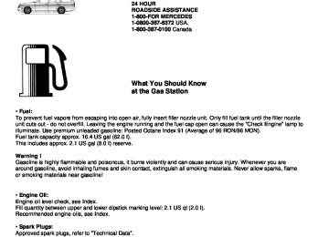
Premium Unleaded Gasoline
Caution ! To maintain the engine's durability and performance, premium unleaded gasoline must be used. If premium unleaded is not available and low octane fuel is used, follow these precautions: • have the fuel tank filled only partially with unleaded regular and fill up with premium unleaded as soon as possible, • avoid full throttle driving and abrupt acceleration, • do not exceed an engine speed of 3000 rpm, if the vehicle is loaded with a light load such as two persons and no luggage, • do not exceed 2/3 of maximum accelerator pedal position, if the vehicle is fully loaded or operating in mountainous terrain.
Fuel Requirements Use only Premium unleaded meeting ASTM standard D 439: The octane number (posted at the pump) must be 91 min. It is an average of both the Research (R) octane number and the Motor (M) octane number: [(R+M)/2]. This is also known as ANTI-KNOCK INDEX. Unleaded gasoline containing oxygenates such as Ethanol, I PA, IBA and TBA can be used provided the ratio of any one of these oxygenates to gasoline does not exceed 10%, MTBE not to exceed 15%. The ratio of Methanol to gasoline must not exceed 3% plus additional components. Using mixtures of Ethanol and Methanol is not allowed. Gasohol, which contains 10% Ethanol and 90% unleaded gasoline, can be used. These blends must also meet all other fuel requirements such as resistance to spark knock, boiling range, vapor pressure etc..
Gasoline Additives A major concern among engine manufacturers is carbon build up caused by gasoline. Mercedes- Benz recommends the use of only quality gasoline containing additives that prevent the build up of carbon deposits. After an extended period of using fuels without such additives, carbon deposits can build up especially on the intake valves and in the combustion area, leading to engine performance problems such as: • warm-up hesitation, • unstable idle, • knocking/pinging, • misfire, • power loss. Do not blend other specific fuel additives with fuel. They only result in unnecessary cost, and may be harmful to the engine operation. Damage or malfunctions resulting from poor fuel quality or from blending specific fuel additives are not covered by the Mercedes-Benz Limited Warranty.
Coolants
The engine coolant is a mixture of water and anticorrosion/antifreeze, which provides: • corrosion protection, • freeze protection, • boiling protection (by increasing the boiling point). The cooling system was filled at the factory with a coolant providing freeze protection to approx. -22°F (-30°C) and corrosion protection. The coolant solution must be used year round to provide the necessary corrosion protection and increase in the boil-over protection. You should have it replaced every 3 years. To provide the important corrosion protection, the solution must be at least 45% anticorrosion/antifreeze (equals a freeze protection to approx. -22°F [-30°C]). If you use a solution that is more than 55% anticorrosion/antifreeze (freeze protection to approx. -49°F [-45°C]), the engine temperature will increase due to the lower heat transfer capability of the solution. Therefore, do not use more than this amount of anticorrosion/antifreeze. If the coolant level is low, water and MB anticorrosion/antifreeze should be used to bring it up to the proper level (have cooling system checked for signs of leakage). The water in the cooling system must meet minimum requirements, which are usually satisfied by normal drinking water. If you are not sure about the water quality, consult your authorized Mercedes-Benz dealer.
Anticorrosion/antifreeze Your vehicle contains a number of aluminum parts. The use of aluminum components in motor vehicle engines necessitates that anticorrosion/antifreeze coolant used in such engines be specifically formulated to protect the aluminum parts. (Failure to use such anticorrosion/antifreeze coolant will result in a significantly shortened service life.) Therefore the following product is strongly recommended for use in your car: Mercedes-Benz Anticorrosion/Antifreeze Agent. Before the start of the winter season (or once a year in the hot southern regions), you should have the anticorrosion/antifreeze concentration checked. The coolant is also regularly checked each time you bring your vehicle to your authorized Mercedes-Benz dealer for service.
Model
C 230 Kompressor
C 280
C 43 AMG
Approx.freeze Protection -35°F (~37°C)
-49°F (-45°C)
5.0 US qt (4.75 I)
5.3 US qt (5.0 I)
5.9US qt (5.6 I)
5.5 US qt (5.25 I)
5.8 US qt (5.5 I)
6.6 US qt (6.2 I)
Consumer Information
This has been prepared as required of all manufacturers of passenger cars under Title 49, Code of U.S. Federal Regulations, Part 575 pursuant to the "National Traffic and Motor Vehicle Safety Act of 1966".
Uniform Tire Quality Grading Refer to the tire sidewall for the specific tire grades for the tires with which this vehicle is equipped. All passenger car tires must conform to federal safety requirements in addition to these grades.
Treadwear The treadwear grade is a comparative rating based on the wear rate of the tire when tested under controlled conditions on a specified government test course. For example, a tire graded 150 would wear one and one-half (11/2) times as well on the government course as a tire graded 100. The relative performance of tires depends upon the actual conditions of their use, however, and may depart significantly from the norm due to variations in driving habits, service practices and differences in road characteristics and climate.
Traction The traction grades, from highest to lowest, are AA, A, B, and C, Those grade represent the tire's ability to stop on wet pavement as measured under controlled conditions on specified government test surfaces of asphalt and concrete. A tire marked "C" may have poor traction performance.
Warning ! The traction grade assigned to this tire is based on straight-ahead braking traction tests and does not include cornering, hydroplaning or peak traction characteristics.
Temperature The temperature grades are A (the highest), B, and C, representing the tire's resistance to the generation of heat and its ability to dissipate heat when tested under controlled conditions on a specified indoor laboratory test wheel. Sustained high temperature can cause the material of the tire to degenerate and reduce tire life, and excessive temperature can lead to sudden tire failure. The grade C corresponds to a level of performance which all passenger car tires must meet under the Federal Motor Vehicle Safety Standard No.109. Grades B and A represent higher levels of performance on the laboratory test wheel than the minimum required by law.
Warning ! The temperature grade for this tire is established for a tire that is properly inflated and not overloaded. Excessive speed, underinflation, or excessive loading, either separately or in combination, can cause excessive heat build up and possible tire failure.
Problems with your Vehicle
If you should experience a problem with your vehicle, particularly one that you believe may affect its safe operation, we urge you to immediately contact your authorized Mercedes-Benz dealer to have the problem diagnosed and corrected if required. If the matter is not handled to your satisfaction, please discuss the problem with the dealership management, or if necessary contact us at the following addresses:
In the U.S.A.: Customer Assistance Center Mercedes-Benz of North America Inc. One Mercedes Drive Montvale, NJ 07645-0350
In Canada: Customer Relations Department Mercedes-Benz Canada Inc. 849 Eglinton Avenue East Toronto, Ontario, M4G 2L5
For the U.S.A. only. The following text is published as required of manufacturers under Title 49, Code of U.S. Federal Regulations, Part 575 pursuant to the "National Traffic and Motor Vehicle Safety Act of 1966".
Reporting Safety Defects
If you believe that your vehicle has a defect which could cause a crash or could cause injury or death, you should immediately inform the National Highway Traffic Safety Administration (NHTSA) in addition to notifying Mercedes-Benz of North America Inc.. If NHTSA receives similar complaints, it may open an investigation, and if it finds that a safety defect exists in a group of vehicles, it may order a recall and remedy campaign. However, NHTSA cannot become involved in individual problems between you, your dealer, or Mercedes-Benz of North America Inc.. To contact NHTSA, you may either call the Auto Safety Hotline toll-free at 1-800-424-9393 (or 366-0123 in Washington, D.C. area) or write to: NHTSA, U.S. Department of Transportation, Washington, D.C. 20590. You can also obtain other information about motor vehicle safety from the Hotline.
Service and Literature
Your authorized Mercedes-Benz dealer has trained technicians and original Mercedes-Benz parts to service your vehicle properly. For expert advice and quality service, see your authorized Mercedes-Benz dealer. If you are interested in obtaining service literature for your vehicle, please contact your authorized Mercedes-Benz dealer. We consider this to be the best way for you to obtain accurate information for your vehicle.
Warning ! To help avoid personal injury, be extremely careful when performing any service work or repairs. Improper or incomplete service or the use of incorrect or inappropriate parts or materials may damage the vehicle or its equipment, which may in turn result in personal injury. If you have any question about carrying out some service, turn to the advice of an authorized Mercedes-Benz dealer.
Check Regularly and Before a Long Trip
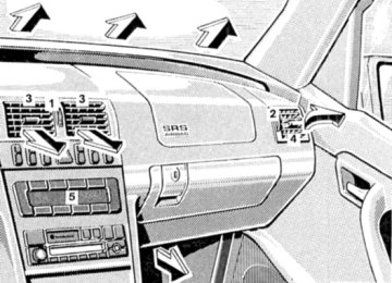
The engine compartment of model C 230 is illustrated. 1. Fuel Supply Open flap by pushing near front (arrow). Turn fuel cap to the left and hold on to it until possible pressure in tank has been released, then remove cap. Failure to remove slowly could result in personal injury. 2. Tire Inflation Pressure Check at least every two weeks. For details see Index. 3. Coolant Level See Adding coolant in Index. 4. Windshield Washer System, Headlamp Cleaning System For refilling reservoir see Index. 5. Engine Oil Level See Engine oil level, checking in Index. 6. Brake Fluid See Brake fluid in Index.
Vehicle Lighting: Check function and cleanliness. For replacement of light bulbs, see Lamps, exterior in Index.