- 2008 Jeep Grand Cherokee SRT8 Owners Manuals
- Jeep Grand Cherokee SRT8 Owners Manuals
- 2012 Jeep Grand Cherokee SRT8 Owners Manuals
- Jeep Grand Cherokee SRT8 Owners Manuals
- 2010 Jeep Grand Cherokee SRT8 Owners Manuals
- Jeep Grand Cherokee SRT8 Owners Manuals
- 2013 Jeep Grand Cherokee SRT8 Owners Manuals
- Jeep Grand Cherokee SRT8 Owners Manuals
- 2009 Jeep Grand Cherokee SRT8 Owners Manuals
- Jeep Grand Cherokee SRT8 Owners Manuals
- 2006 Jeep Grand Cherokee SRT8 Owners Manuals
- Jeep Grand Cherokee SRT8 Owners Manuals
- 2007 Jeep Grand Cherokee SRT8 Owners Manuals
- Jeep Grand Cherokee SRT8 Owners Manuals
- Download PDF Manual
-
Sunroof Fully Closed Press the switch forward and release to ensure that the sunroof is fully closed.
Sunshade Operation The sunshade can be opened manually. However, the sunshade will open automatically as the sunroof opens. NOTE: The sunshade cannot be closed if the sunroof is open. Wind Buffeting Wind buffeting can be described as the perception of pressure on the ears or a helicopter type sound in the ears. Your vehicle may exhibit wind buffeting with the windows down, or the sunroof (if equipped) in certain open or partially open positions. This is a normal occur- rence and can be minimized. If the buffeting occurs with the rear windows open, open the front and rear windows together to minimize the buffeting. If the buffeting occurs with the sunroof open, adjust the sunroof opening to minimize the buffeting or open any window.
160 UNDERSTANDING THE FEATURES OF YOUR VEHICLE
POWER OUTLET To the right of the convenience tray (lower center of instrument panel) is an outlet for electrically powered accessories. Pull lightly on the tab of the plastic cover to access the outlet.
The rear power outlet (if equipped) is located in the left rear cargo area.
Front Power Outlet
Rear Power Outlet
The power outlets are a direct feed from the battery so they receive power whether the ignition is in the ON or OFF position.
All accessories connected to this outlet should be re- moved or turned off when the vehicle is not in use to protect the battery against discharge.
UNDERSTANDING THE FEATURES OF YOUR VEHICLE 161
CAUTION!
Electrical Outlet Use With Engine Off • Many accessories that can be plugged in draw power from the vehicle’s battery, even when not in use (i.e., cellular phones, etc.). Eventually, if plugged in long enough, the vehicle’s battery will discharge sufficiently to degrade battery life and/or prevent engine starting. • Accessories that draw higher power (i.e., coolers, vacuum cleaners, lights, etc.) will degrade the battery even more quickly. Only use these inter- mittently and with greater caution. • After the use of high power draw accessories, or long periods of the vehicle not being started (with accessories still plugged in), the vehicle must be driven a sufficient length of time to allow the generator to recharge the vehicle’s battery.
162 UNDERSTANDING THE FEATURES OF YOUR VEHICLE
CUP HOLDERS In the center console there are two cup holders for the front seat passengers.
cup depression towards the passenger seat, but the top surface will not be flush with the console surface. The rear passengers have access to two cup holders that pull out from the lower center of the rear seat.
Front Cup Holders
NOTE: The cup holder insert is removable, from the console, for cleaning. It can be reinstalled with the larger
Rear Cup Holders
CARGO AREA FEATURES
Cargo Light The cargo area light is activated by opening the liftgate, opening any door, or by rotating the dimmer control on the multi-function control lever to the extreme top posi- tion. If all doors are closed and only the liftgate is open, pushing on the cargo light lens surface will turn off all interior lamps. Push on the lens surface a second time to restore the interior lights to normal operation.
UNDERSTANDING THE FEATURES OF YOUR VEHICLE 163
Rear Storage Compartment The rear storage compartment is located on the driver’s side behind the second row seat.
Rear Storage Compartment
164 UNDERSTANDING THE FEATURES OF YOUR VEHICLE
Retractable Cargo Area Cover
NOTE: The purpose of this cover is for privacy, not to secure loads. It will not prevent cargo from shifting or protect passengers from loose cargo. To cover the cargo area: 1. Grasp the cover at the center handle. Pull it over the cargo area. 2. Insert the pins on the ends of the cover into the slots in the pillar trim cover. 3. The liftgate may be opened with the cargo cover in place.
Rear Cargo Cover
WARNING!
In an accident a cargo cover loose in the vehicle could cause injury. It could fly around in a sudden stop and strike someone in the vehicle. Do not store the cargo cover on the cargo floor or in the passenger compartment. Remove the cover from the vehicle when taken from its mounting. Do not store in the vehicle.
Cargo Tie-Down Hooks The tie-downs located on cargo area floor should be used to safely secure loads when vehicle is moving.
UNDERSTANDING THE FEATURES OF YOUR VEHICLE 165
Cargo Tie-Down Hooks
166 UNDERSTANDING THE FEATURES OF YOUR VEHICLE
WARNING!
Cargo tie-down hooks are not safe anchors for a child seat tether strap. In a sudden stop or collision a hook could pull loose and allow the child seat to come loose. A child could be badly injured. Use only the anchors provided for child seat tethers.
WARNING!
The weight and position of cargo and passengers can change the vehicle center of gravity and vehicle handling. To avoid loss of control resulting in per- sonal injury, follow these guidelines for loading your vehicle:
• Do not carry loads which exceed the load limits described on the label attached to the left door or left door center pillar. • Always place cargo evenly on the cargo floor. Put heavier objects as low and as far forward as possible. • Place as much cargo as possible in front of the rear axle. Too much weight or improperly placed weight over or behind the rear axle can cause the rear of the vehicle to sway. • Do not pile luggage or cargo higher than the top of the seatback. This could impair visibility or become a dangerous projectile in a sudden stop or collision.
WARNING!
To help protect against personal injury, passengers should not be seated in the rear cargo area. The rear cargo space is intended for load carrying purposes only, not for passengers, who should sit in seats and use seat belts.
Cargo Load Floor
The panel in the load floor is reversible for added utility. One side is carpeted and the other side features a plastic lined tray which holds a variety of items.
UNDERSTANDING THE FEATURES OF YOUR VEHICLE 167
Cargo Load Floor
The cargo load floor is held by spring loaded latches. In order to use the cargo load floor, use the following procedure: NOTE: used as cargo tie-downs.
The cargo load floor latches should not be
168 UNDERSTANDING THE FEATURES OF YOUR VEHICLE
1. Flip up pull loop(s) so they are perpendicular (straight up) to the top surface of the tray. 2. Pull up on loop(s) and twist 90 degrees, so they are parallel to the slotted hole in tray. 3. Lift tray over loop(s), and reposition tray. 4. Pull up on loop(s) and twist 90 degrees, so they are perpendicular (straight up) to the slotted hole in tray. 5. Push loop(s) back down, so they are parallel to the top of the tray.
REAR WINDOW FEATURES
Rear Window Wiper/Washer A switch on the right side of the steering column controls operation of the rear wiper/washer function. Rotating the center of the switch up to the DEL (Delay) position or the ON position will activate the wiper. Rotating the center of the switch all the way up or down will turn on
the wash function. The wash pump will continue to operate as long as the button is pressed. Upon release, the wipers will cycle three times before returning to the set position.
Rear Wiper/Washer Switch
If the rear wiper is operating when the ignition is turned OFF, the wiper will automatically return to the “Park” position. If the liftgate flipper glass is open, connection to the rear window wiper is interrupted preventing activation of the rear wiper blade. When the liftgate flipper glass is closed, the rear wiper switch or the ignition switch needs to be turned OFF and ON to restart the rear wiper.
UNDERSTANDING THE FEATURES OF YOUR VEHICLE 169
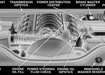
Adding Washer Fluid The fluid reservoir for the windshield washers and the rear window washer is shared. It is located in the front of the engine compartment on the passenger side and should be checked for fluid level at regular intervals. Fill the reservoir with windshield washer solvent (not radia- tor antifreeze) and operate the system for a few seconds to flush out the residual water.
UNDERSTANDING YOUR INSTRUMENT PANEL
CONTENTS
䡵 Instrument Panel And Interior Controls . . . . . . . 174
䡵 Instrument Cluster . . . . . . . . . . . . . . . . . . . . . . 175
䡵 Instrument Cluster Description . . . . . . . . . . . . . 176
䡵 Electronic Vehicle Information Center . . . . . . . . 183
▫ Customer Programmable Features . . . . . . . . . 186
▫ Compass/Temperature/Trip Computer . . . . . . 190
▫ Trip Computer . . . . . . . . . . . . . . . . . . . . . . . 192
䡵 Radio General Information . . . . . . . . . . . . . . . . 197
▫ Radio Broadcast Signals . . . . . . . . . . . . . . . . . 197▫ Two Types Of Signals . . . . . . . . . . . . . . . . . . 197
▫ Electrical Disturbances . . . . . . . . . . . . . . . . . . 197
▫ AM Reception . . . . . . . . . . . . . . . . . . . . . . . 197
▫ FM Reception . . . . . . . . . . . . . . . . . . . . . . . . 198䡵 Sales Code RAQ – AM/FM/CD (6-Disc) Radio
With Optional Satellite Radio, Hands Free Phone, And Vehicle Entertainment Systems (VES) Capabilities . . . . . . . . . . . . . . . . . . . . . . . . . . . 198
▫ Operating Instructions - Radio Mode . . . . . . . 198172 UNDERSTANDING YOUR INSTRUMENT PANEL
▫ Operation Instructions -
(CD Mode For CD Audio Play)
. . . . . . . . . . . 204
▫ Load/Eject Button
(CD Mode For CD Audio Play)
▫ Notes On Playing MP3 Files ▫ Operation Instructions -
. . . . . . . . . . . 205
. . . . . . . . . . . . . 207(CD Mode For MP3 Audio Play)
. . . . . . . . . . 210
▫ Load/Eject Button (CD Mode For MP3 Play) . . 210䡵 Sales Code REC — AM/FM/CD (6–Disc) Radio
With Navigation System . . . . . . . . . . . . . . . . . . 212
▫ Operating Instructions — Satellite Radio(If Equipped)
. . . . . . . . . . . . . . . . . . . . . . . . 213
▫ Clock Setting Procedure . . . . . . . . . . . . . . . . . 213䡵 Video Entertainment System (Sales Code XRV) —
If Equipped . . . . . . . . . . . . . . . . . . . . . . . . . . . 214
䡵 Satellite Radio — If Equipped . . . . . . . . . . . . . . 216
▫ System Activation . . . . . . . . . . . . . . . . . . . . . 216
▫ Electronic Serial Number/Sirius IdentificationNumber (ESN/SID) . . . . . . . . . . . . . . . . . . . . 216
▫ Selecting Satellite Mode In RAQ Radios . . . . . 217
▫ Selecting a Channel . . . . . . . . . . . . . . . . . . . . 217
▫ Storing And Selecting Pre-Set Channels . . . . . . 218
▫ Using The PTY (Program Type) Button —If Equipped . . . . . . . . . . . . . . . . . . . . . . . . . 218
▫ PTY Button ⬙Scan⬙ . . . . . . . . . . . . . . . . . . . . . 218
▫ PTY Button ⬙Seek⬙ . . . . . . . . . . . . . . . . . . . . . 218
▫ Satellite Antenna . . . . . . . . . . . . . . . . . . . . . . 218
▫ Reception Quality . . . . . . . . . . . . . . . . . . . . . 219
䡵 Remote Sound System Controls . . . . . . . . . . . . . 219▫ Radio Operation . . . . . . . . . . . . . . . . . . . . . . 220
▫ CD Player . . . . . . . . . . . . . . . . . . . . . . . . . . 220
䡵 CD/DVD Disc Maintenance . . . . . . . . . . . . . . . 221
䡵 Radio Operation And Cellular Phones . . . . . . . . 221
䡵 Climate Controls . . . . . . . . . . . . . . . . . . . . . . . 222
. . . . . . . . . . . 222▫ Automatic Temperature Control
UNDERSTANDING YOUR INSTRUMENT PANEL 173
▫ Summer Operation . . . . . . . . . . . . . . . . . . . . 228
▫ Winter Operation . . . . . . . . . . . . . . . . . . . . . 228
▫ Vacation Storage . . . . . . . . . . . . . . . . . . . . . . 229
▫ Window Fogging . . . . . . . . . . . . . . . . . . . . . 229
▫ Outside Air Intake . . . . . . . . . . . . . . . . . . . . 229174 UNDERSTANDING YOUR INSTRUMENT PANEL
INSTRUMENT PANEL AND INTERIOR CONTROLS
INSTRUMENT CLUSTER
UNDERSTANDING YOUR INSTRUMENT PANEL 175
176 UNDERSTANDING YOUR INSTRUMENT PANEL
INSTRUMENT CLUSTER DESCRIPTION
1. Speedometer Indicates vehicle speed. 2. Brake Warning Light
The BRAKE warning light will come on when the ignition is first turned on, and stay on briefly as a bulb check. If the bulb does not come on during starting, have the bulb re- paired promptly. If the light stays on longer, it may be an indication that the parking brake has not been released. If the light remains on when the parking brake is off, it indicates a possible brake hydraulic system malfunction or low fluid level. In this case, the light will remain on until the cause is corrected. If a brake malfunction is indicated, immediate repair is necessary and continued operation of the vehicle in this condition is dangerous.
3. Turn Signal Indicator Light
The arrow will flash with the exterior turn signal when the turn signal lever is operated.
If the vehicle electronics sense that the vehicle has traveled about one mile with the turn signals on, a chime will sound to alert you to turn the signals off. If either indicator flashes at a rapid rate, check for a defective outside light bulb. 4. High Beam Indicator Light
Indicates that headlights are on high beam.
5. Malfunction Indicator Light
This light is part of an onboard diagnostic system called OBD II that monitors engine and auto- matic transmission control systems. The light will illuminate when the key is in the ON position before
engine start. If the bulb does not come on when turning the key from OFF to ON, have the condition checked promptly. Certain conditions such as a loose or missing gas cap, poor fuel quality, etc. may illuminate the light after engine start. The vehicle should be serviced if the light stays on through several of your typical driving cycles. In most situations the vehicle will drive normally and will not require towing. The Malfunction Indicator Light flashes to alert you to serious conditions that could lead to immediate loss of power or severe catalytic converter damage. The vehicle should be serviced as soon as possible if this occurs. (See page 297 for more information.)
UNDERSTANDING YOUR INSTRUMENT PANEL 177
6. Airbag Warning Light
This light turns on and remains on for 6 to 8
seconds as a bulb check when the ignition switch is first turned ON. If the light is not on during starting, stays on, or turns on while driving, have the system inspected by an authorized dealer as soon as possible. 7. Anti-Lock Brake Warning LightThis light monitors the Anti-Lock Brake System. The light will turn on when the ignition switch is turned to the ON position and may stay on for as long as four seconds. If the ABS light remains on or turns on while driving, it indicates that the Anti-Lock portion of the brake system is not functioning and that service is required. However, the conventional brake system will continue to operate normally if the BRAKE warning light is not on.
178 UNDERSTANDING YOUR INSTRUMENT PANEL
If the ABS light is on, the brake system should be serviced as soon as possible to restore the benefits of Anti-Lock brakes. If the ABS light does not turn on when the Ignition switch is turned to the ON position, have the light inspected by an authorized dealer. 8. Tachometer The red segments indicate the maximum permissible engine revolutions-per-minute (r.p.m. x 1000) for each gear range. Before reaching the red area, ease up on the accelerator. 9. Security Alarm System Indicator Light — If Equipped This light will flash rapidly for approximately 15 seconds when the vehicle theft alarm is arming. The light will flash at a slower speed continuously after the alarm is set. The security light will also come on for about three seconds when the ignition is first turned on.
10. Oil Pressure Warning Light
This light shows low engine oil pressure. The light should turn on momentarily when the engine is started. If the light turns on while driving, stop the vehicle, and shut off the engine as soon as possible. A continuous chime will sound when this light turns on. Do not operate the vehicle until the cause is corrected. This light does not show how much oil is in the engine. The engine oil level must be checked under the hood. 11. Electronic Stability Program (ESP) Indicator Light/Traction Control System (TCS) Indicator Light
This indicator light starts to flash as soon as the tires lose traction and the ESP system becomes active. The “ESP/TCS Indicator Light” also flashes when TCS is active. If the “ESP/TCS Indicator Light” begins to flash during acceleration, ease up on the accelerator and apply as little throttle as possible. Be sure to adapt your speed and driving to the
prevailing road conditions. The “ESP/TCS Indicator Light” will flash any time the ESP or TCS is active and helping to improve vehicle stability. If the “ESP/TCS Indicator Light” is on solid, the ESP system has been turned off by the driver or a temporary condition exists that will not allow full ESP function. (See page 130 for more information.) 12. Tire Pressure Monitoring Telltale Light
Each tire, including the spare (if provided), should be checked monthly when cold and inflated to the inflation pressure recommended by the vehicle manufacturer on the vehicle placard or tire inflation pressure label. (If your vehicle has tires of a different size than the size indicated on the vehicle placard or tire inflation pressure label, you should determine the proper tire inflation pressure for those tires.)
UNDERSTANDING YOUR INSTRUMENT PANEL 179
As an added safety feature, your vehicle has been equipped with a tire pressure monitoring system (TPMS) that illuminates a low tire pressure telltale when one or more of your tires is significantly under-inflated. Accord- ingly, when the low tire pressure telltale illuminates, you should stop and check your tires as soon as possible, and inflate them to the proper pressure. Driving on a signifi- cantly under-inflated tire causes the tire to overheat and can lead to tire failure. Under-inflation also reduces fuel efficiency and tire tread life, and may affect the vehicle’s handling and stopping ability. Please note that the TPMS is not a substitute for proper tire maintenance, and it is the driver’s responsibility to maintain correct tire pressure, even if under-inflation has not reached the level to trigger illumination of the TPMS low tire pressure telltale.
180 UNDERSTANDING YOUR INSTRUMENT PANEL
13. Temperature Gauge The temperature gauge shows engine coolant tempera- ture. Any reading within the normal range indicates that the engine cooling system is operating satisfactorily. The gauge pointer will likely indicate a higher tempera- ture when driving in hot weather, up mountain grades, or when towing a trailer. It should not be allowed to exceed the upper limits of the normal operating range.
CAUTION!
Driving with a hot engine cooling system could damage your vehicle. If temperature gauge reads (H), pull over and stop the vehicle. Idle the vehicle with the air conditioner turned off until the pointer drops back into the normal range. If the pointer remains on the “H”, and you hear continuous chimes, turn the engine off immediately, and call for service.
WARNING!
A hot engine cooling system is dangerous. You or others could be badly burned by steam or boiling coolant. If you decide to look under the hood your- self, refer to Section 7 of this manual. Follow the warnings under “Cooling System Pressure Cap.”
14. Electronic Vehicle Information Center Display When the appropriate conditions exist, this display shows the Electronic Vehicle Information Center (EVIC) messages. Refer to “Electronic Vehicle Information Cen- ter” later in this section. 15. Electronic Stability Program (ESP) Warning Light/Brake Assist System (BAS) Warning Light — If Equipped
The ESP/BAS warning light in the instrument cluster comes on when the ignition switch is turned to the “ON” position. The light should go out with the engine running. If the ESP/ BAS warning light comes on continuously with the engine running, a malfunction has been detected in either the ESP or the BAS system. If this light stays illuminated, have the ESP and BAS checked at your authorized dealer as soon as possible.
UNDERSTANDING YOUR INSTRUMENT PANEL 181
16. Seat Belt Reminder Light
When the ignition switch is first turned ON, this light will turn on for 5 to 8 seconds as a bulb check. During the bulb check, if the driver’s seat belt is unbuckled, a chime will sound. After the bulb check or when driving, if the driver or front passenger seat belt remains unbuckled, the Seat Belt Warning Light will flash or remain on continuously. Refer to ⬙Occupant Restraints — Enhanced Driver Seat Belt Reminder System (BeltAlert)⬙ in Section 2 for more information. 17. Cruise Indicator Light
This indicator lights when the speed control system is turned ON.
18. Odometer The odometer shows the total distance the vehicle has been driven.
182 UNDERSTANDING YOUR INSTRUMENT PANEL
U.S. federal regulations require that upon transfer of vehicle ownership, the seller certify to the purchaser the correct mileage that the vehicle has been driven. There- fore, if the odometer reading is changed during repair or replacement, be sure to keep a record of the reading before and after the service so that the correct mileage can be determined. 19. Transmission Range Indicator This display indicator shows the automatic transmission gear selection. 20. Fuel Gauge The pointer shows the level of fuel in the fuel tank when the ignition switch is in the ON position.
21. Electronic Throttle Control (ETC) Warning Light
This light informs you of a problem with the Electronic Throttle Control system. If a problem is detected the light will come on while the engine is running. Cycle the ignition key when the vehicle has completely stopped and the gear selector is placed in the P (Park) position. The light should turn off. If the light remains lit with the engine running your vehicle will usually be drivable, however, see your dealer for service as soon as possible. If the light is flashing when the engine is running, immediate service is re- quired and you may experience reduced performance, an elevated/rough idle or engine stall and your vehicle may require towing. The light will come on when the ignition is first turned on and remain on briefly as a bulb check. If the light does not come on during starting, have the system checked by an authorized dealer.
22. Front Fog Light Indicator Light— If Equipped This light shows the front fog lights are ON.
UNDERSTANDING YOUR INSTRUMENT PANEL 183
ELECTRONIC VEHICLE INFORMATION CENTER
23. Voltage Warning Light
This light monitors the electrical system voltage. The light should turn on momentarily as the engine is started. If the light stays on or turns on while driving, it indicates a problem with the charging system. Immediate service should be obtained. 24. Low Fuel Warning Light
When the fuel level reaches approximately 2.3 U.S. Gallons (8.7 Liters) this light will come on and remain on until fuel is added. The Low Fuel Warning Light may turn on and off again, especially during and after hard braking, accelerations, or turns. This occurs due to the shifting of the fuel in the tank. Also, a single chime will sound.
The electronic vehicle information center (EVIC) located in the instrument cluster, when the appropriate condi- tions exist, will display the following messages and symbols. Some of the messages are accompanied by a chime. • TURN SIGNAL ON
184 UNDERSTANDING YOUR INSTRUMENT PANEL
GRAMMED
GRAM LIMIT
• PERFORM SERVICE • KEY NOT PROGRAMMED — DAMAGED KEY • KEY NOT PROGRAMMED — INVALID KEY • KEY NOT PROGRAMMED — EXCEEDED KEY PRO- • PROGRAMMING ACTIVE — NEW KEY PRO- • SERVICE SECURITY KEY • INVALID KEY — TRY ALTERNATE KEY • DRIVER/PASSENGER DOOR OPEN (with graphic) • LEFT/RIGHT REAR DOOR OPEN (with graphic) • X DOORS OPEN (with graphic) • LIFTGATE OPEN (with graphic) • LIFTGATE/DOOR OPEN (with graphic)
• LIFTGATE/DOORS OPEN (with graphic) • LIFTGLASS OPEN (with graphic) • HOOD OPEN (with graphic) • HOOD/DOOR OPEN (with graphic) • HOOD/DOORS OPEN (with graphic) • LIFTGATE/HOOD OPEN (with graphic) • HOOD/GLASS/DOOR OPEN (with graphic) • HOOD/GLASS/DOORS OPEN (with graphic) • HOOD/GATE/DOOR OPEN (with graphic) • HOOD/GATE/DOORS OPEN (with graphic) • LIFTGLASS/DOOR OPEN (with graphic) • LIFTGLASS/DOORS OPEN (with graphic) • LIFTGLASS/HOOD OPEN (with graphic)
• WASHER FLUID LOW (with graphic) • UPSHIFT (with graphic) • CHECK GAUGES • AUTO HIGHBEAM ON • AUTO HIGHBEAM OFF • PARK ASSIST DISABLED • SERVICE PARK ASSIST SYSTEM • TRANSMISSION OVER TEMP • LOW BRAKE FLUID LEVEL • WARNING! LIMIT SPEED • CHECK GAS CAP • ESP OFF • MEMORY #1 POSITIONS SET
UNDERSTANDING YOUR INSTRUMENT PANEL 185
PARK
TENED (with graphic)
• MEMORY #2 POSITIONS SET • MEMORY SYSTEM DISABLED — SEATBELT FAS- • MEMORY SYSTEM DISABLED — VEHICLE NOT IN • DRIVER 1 MEMORY • DRIVER 2 MEMORY • PEDAL ADJUST DISABLED — CRUISE CONTROL • PEDAL ADJUST DISABLED — SHIFTER IN RE- • SERVICE TIRE PRESS SYSTEM • LEFT FRONT LOW PRESSURE • RIGHT FRONT LOW PRESSURE
VERSE
SET
186 UNDERSTANDING YOUR INSTRUMENT PANEL
• LEFT REAR LOW PRESSURE • RIGHT REAR LOW PRESSURE Customer Programmable Features Press the MENU button until one of the display choices following appears:
Language? When in this display you may select one of three languages for all display nomenclature, including the trip computer functions. Press the STEP button while in this display selects English, Espanol, or Francais. As you continue the displayed information will be shown in the selected language.
Menu Button
Step Button
Display U.S. or Metric? Pressing the STEP button when in this display selects US or Metric. The overhead console and instrument panel displays will be in the selected units. Auto Door Locks? When this feature is selected, all doors and the liftgate lock automatically when the speed of the vehicle reaches 15 mph (25 km/h). Pressing the STEP button when in this display will select “Yes” or “No.” Auto Unlock On Exit? (Available Only When the AUTO DOOR LOCKS Feature is Turned On ) When this feature is selected all the vehicle’s doors will unlock when the driver’s door is opened if the vehicle is stopped and the transmission is in P (Park) or N (Neu- tral) position. Pressing the STEP button when in this display will select “Yes” or “No.”
UNDERSTANDING YOUR INSTRUMENT PANEL 187
Remote Unlock Driver’s Door 1st? When this feature is selected only the driver’s door will unlock on the first press of the remote keyless entry unlock button and require a second press to unlock the remaining locked doors and liftgate. When REMOTE UNLOCK ALL DOORS is selected all of the doors and the liftgate will unlock at the first press of the remote keyless entry unlock button. Pressing the STEP button when in this display will select DRIVER’S DOOR 1ST or ALL DOORS. Remote Linked To Memory? (Available with Memory Seat Only) When this feature is selected the memory seat, mirror, and radio settings will return to the memory set position when the remote keyless entry “Unlock” button is pressed. If this feature is not selected then the memory seat, mirror, and radio settings can only return to the
188 UNDERSTANDING YOUR INSTRUMENT PANEL
memory set position using the door mounted switch. Pressing the STEP button when in this display will select “Yes” or “No.” Sound Horn With Lock? When this feature is selected a short horn sound will occur when the remote keyless entry “Lock” button is pressed. This feature may be selected with or without the flash lights on lock/unlock feature. Pressing the STEP button when in this display will select “Yes” or “No.” Flash Lights With Lock? When this feature is selected, the front and rear turn signals will flash when the doors are locked or unlocked using the remote keyless entry transmitter. This feature may be selected with or without the sound horn on lock feature selected. Pressing the STEP button when in this display will select “Yes” or “No.”
Headlamp Delay When this feature is selected the driver can choose, when exiting the vehicle, to have the headlamps remain on for 30, 60, or 90 seconds, or not remain on. Pressing the STEP button when in this display will select 30, 60, 90, or OFF. Illuminated Approach? When this feature is selected the driver can choose, when entering the vehicle, to have the headlamps come on for 30, 60, or 90 seconds, or not come on at all. Pressing the STEP button when in this display will select 30, 60, 90, or OFF. Auto Headlamp Low/High Beams? (Available with SmartBeam Only) When this feature is selected and the headlight switch has been moved to the A (Auto) position, the headlights will automatically switch from high to low beams when approaching a vehicle. Pressing the STEP button when in
this display will select “Low Beam” or “Low/High Beam.” Refer to “Lights — SmartBeams” in Section 3 of this manual. NOTE: System will activate at or above 20 mph (32
km/h). Headlamps On With Wipers? (Available with Auto Headlights Only) When this feature is selected and the headlight switch has at least once been moved to the A (Auto) position, the headlights will turn on when the wipers are turned on. The headlights will also turn off when the wipers are turned off if they were turned on in this way. Pressing the STEP button when in this display will select “Yes” or “No.” NOTE: Turning the headlights on during the daytime causes the instrument panel lights to dim. To increase the brightness, refer to “Lights” in Section 3 of this manual.UNDERSTANDING YOUR INSTRUMENT PANEL 189
Front Wipers Rain Sense? (Available with Rain Sensing Wipers Only) Pressing the STEP button when in this display will select “Manual” or “Rain Sense.” Service Interval When this feature is selected a service interval between 2,000 (3 200 km) and 6,000 miles (10 000 km) in 500 mile (800 km) increments may be selected. Pressing the STEP button when in this display will select distances between 2,000 (3 200 km) and 6,000 miles (10 000 km) in 500 mile (800 km) increments. Reset Service Distance (Displays Only if Service Interval was Changed) When this feature is selected the current accumulated service distance can be reset to the newly selected service interval. Pressing the STEP button when in this display will select “Yes” or “No.”
190 UNDERSTANDING YOUR INSTRUMENT PANEL
Easy Entry/Exit Seat? (Available with Memory Seat Only) This feature provides automatic driver’s seat positioning which will enhance driver mobility out of and into the vehicle. The Easy Entry/ Easy Exit feature is not enabled when the vehicle is delivered from the factory. The Easy Entry/ Easy Exit feature is enabled (or later disabled) through the programmable features in the Electronic Vehicle Information Center (EVIC). Pressing the STEP button when in this display will select “Yes” or “No.” The seat will return to the memorized seat location (if REMOTE LINK TO MEMORY is set to YES) when the remote keyless entry transmitter is used to unlock the door. For more information, refer to “Easy Entry/Exit Seat — Driver Memory Seat” in Section 3 of this manual.
Compass/Temperature/Trip Computer This display provides the outside temperature, one of the eight compass headings to indicate the direction the vehicle is facing, and vehicle trip information. The compass and temperature display is the normal display. When the C/T button is pressed the compass/temperature display returns.
Compass/Temperature Button
WARNING!
Even if the display still reads a few degrees above 32°F ( 0°C), the road surface may be icy, particularly in woods or on bridges. Drive carefully under such conditions to prevent an accident and possible per- sonal injury or property damage.
UNDERSTANDING YOUR INSTRUMENT PANEL 191
Compass/Temperature Display
192 UNDERSTANDING YOUR INSTRUMENT PANEL
Trip Computer This feature, located in the instrument cluster, displays the following information when the display is in the “Compass/Temperature” mode and the STEP button is pressed: Step Button Press the STEP button to cycle through all of Compass/Mini-Trip Computer displays.
the
Step Button
Reset Button Press the RESET button to reset the display you are in. Press and hold the RESET button (for 2 seconds) to reset all of the displays.
Reset Button
Average Fuel Economy Shows the average fuel economy since the last reset.
UNDERSTANDING YOUR INSTRUMENT PANEL 193
Distance To Empty Shows the estimated distance that can be travelled with the fuel remaining in the tank. This is calibrated using the miles per gallon during the last driving period. Trip A Shows the total distance travelled for trip A since the last reset. Trip B Shows the total distance travelled for trip B since the last reset. Elapsed Time Shows the accumulated ignition ON time since the last reset. Engine Oil Pressure Shows the current engine oil pressure. The scale will read from 0–100 psi (0–689 kPa).
194 UNDERSTANDING YOUR INSTRUMENT PANEL
Engine Oil Temperature Shows the current engine oil temperature. The scale will read from 140° – 300°F (60° – 149°C). Tire Pressure Display Shows the current pressure of all 4 road tires.
Tire Pressure Display
NOTE: Tires heat up during normal driving conditions. Heat will cause the tire pressure to increase from 2 to 6
psi (14 to 41 kPa) during normal driving conditions. Refer to “Tire Inflation Pressures” in Section 5 for additional information. Miles to Service Shows the distance remaining to require service. NOTE: This display can be reset to the set service interval by pressing and holding the RESET button for 3
seconds. Blank Screen Shows a blank screen. Pressing the C/T button returns to the compass/temperature display. Manual Compass Calibration If the compass appears erratic and the “CAL” symbol does not appear, you must manually put the compass into the “Calibration” mode.Set
the display to
NOTE: To ensure proper compass calibration, make sure the compass variance is properly set before manu- ally calibrating the compass. Refer to Variance Map. To Put Into a Calibration Mode Start the engine, and leave the transmission in the P (Park) position. “Compass/ Temperature.” Press and hold the C/T button for ap- proximately 5 seconds to change the display to compass variance mode; holding the button for an additional 5
seconds will flash the “CAL” symbol indicating compass calibration mode. When the “CAL” indicator is flashing, complete one or more 360 degree turns, under 5 mph (8
km/h), in an area free from large metal objects or power lines. The “CAL” indicator will turn off and the compass will function normally.UNDERSTANDING YOUR INSTRUMENT PANEL 195
Compass/Temperature Button
196 UNDERSTANDING YOUR INSTRUMENT PANEL
Compass Variance is the difference between magnetic north and geographic north. In some areas of the country, the difference between magnetic and geographic north is great enough to cause the compass to give false readings. If this occurs, the compass variance must be set according to the Compass Variance Map.
To set the variance: Turn the ignition ON and set the display to “Compass/Temperature.” Press the C/T but- ton approximately 5 seconds. The last variance zone number will be displayed. Press and hold the STEP button for 1 second to select the new variance zone and press the RESET button to resume normal operation.
RADIO GENERAL INFORMATION
Radio Broadcast Signals Your new radio will provide excellent reception under most operating conditions. Like any system, however, car radios have performance limitations, due to mobile op- eration and natural phenomena, which might lead you to believe your sound system is malfunctioning. To help you understand and save you concern about these “ap- parent” malfunctions, you must understand a point or two about the transmission and reception of radio sig- nals.
UNDERSTANDING YOUR INSTRUMENT PANEL 197
Two Types of Signals There are two basic types of radio signals... AM or Amplitude Modulation, in which the transmitted sound causes the amplitude, or height, of the radio waves to vary... and FM or Frequency Modulation, in which the frequency of the wave is varied to carry the sound. Electrical Disturbances Radio waves may pick up electrical disturbances during transmission. They mainly affect the wave amplitude, and thus remain a part of the AM reception. They interfere very little with the frequency variations that carry the FM signal. AM Reception AM sound is based on wave amplitude, so AM reception can be disrupted by such things as lightning, power lines and neon signs.
198 UNDERSTANDING YOUR INSTRUMENT PANEL
FM Reception Because FM transmission is based on frequency varia- tions, interference that consists of amplitude variations can be filtered out, leaving the reception relatively clear, which is the major feature of FM radio. NOTE: On vehicles so equipped the radio, steering wheel radio controls and 6 disc CD/DVD changer will remain active for up to 45 seconds after the ignition switch has been turned off. Opening a vehicle front door will cancel this feature.
SALES CODE RAQ – AM/FM/CD (6-DISC) RADIO WITH OPTIONAL SATELLITE RADIO, HANDS FREE PHONE, AND VEHICLE ENTERTAINMENT SYSTEMS (VES) CAPABILITIES
NOTE: The radio sales code is located on the lower right side of your radio faceplate.
Operating Instructions - Radio Mode
RAQ Radio
NOTE: The ignition switch must be in the ON or ACC position to operate the radio.
Power Switch/Volume Control (Rotary) Press the ON/VOL control to turn the radio ON. Press the ON/VOL a second time to turn OFF the radio. Electronic Volume Control The electronic volume control turns continuously (360
degrees) in either direction without stopping. Turning the volume control to the right increases the volume and to the left decreases it. When the audio system is turned on, the sound will be set at the same volume level as last played. For your convenience, the volume can be turned down, but not up, when the audio system is off and the ignition is ON. Mode Button (Radio Mode) Press the mode button repeatedly to select between the CD player, Satellite Radio, or Vehicle Entertainment System (VES) (if equipped).UNDERSTANDING YOUR INSTRUMENT PANEL 199
SEEK Button (Radio Mode) Press and release the SEEK button to search for the next listenable station in either AM/FM or Satellite (if equipped) mode. Press the right side of the button to seek up and the left side to seek down. The radio will remain tuned to the new station until you make another selec- tion. Holding the button will bypass stations without stopping until you release it. MUTE Button (Radio Mode) Press the MUTE button to cancel the sound from the speakers. ⬙MUTE⬙ will be displayed. Press the MUTE button a second time and the sound from the speakers will return. Rotating the volume control, turning the radio ON/OFF, or turning OFF the ignition will also return the sound from the speakers NOTE: MUTE button mutes the microphone.
In Hands Free Phone (if equipped) mode, the
200 UNDERSTANDING YOUR INSTRUMENT PANEL
SCAN Button (Radio Mode) Pressing the SCAN button causes the tuner to search for the next listenable station, in either AM, FM or Satellite (if equipped) frequencies, pausing for 5 seconds at each listenable station before continuing to the next. To stop the search, press SCAN a second time. MSG or INFO Button (Radio Mode) Press the MSG or INFO button for an RBDS station (one with call letters displayed). The radio will return a Radio Text message broadcast from an FM station (FM mode only). Time Button Press the time button and the time of day will be displayed for 5 seconds. Clock Setting Procedure 1. Press and hold the time button until the hours blink.
2. Adjust the hours by turning the right side Tune / Audio control. 3. After the hours are adjusted, press the right side Tune / Audio control to set the minutes. The minutes will begin to blink. 4. Adjust the minutes using the right side Tune / Audio control. 5. To exit, press any button/knob or wait 5 seconds. RW/FF (Radio Mode) Pressing the rewind/fast forward button causes the tuner to search for the next frequency in the direction of the arrows. This feature operates in either AM, FM or Satel- lite (if equipped) frequencies. TUNE Control (Radio Mode) Turn the right side rotary control clockwise to increase or counter-clockwise to decrease the frequency.
AM/FM Button (Radio Mode) Press the button to select AM or FM Modes. Setting the Tone, Balance, and Fade Press the rotary TUNE control and BASS will display. Turn the TUNE control to the right or left to increase or decrease the Bass tones. Press the rotary TUNE control a second time and MID will display. Turn the TUNE control to the right or left to increase or decrease the Mid Range tones. Press the rotary TUNE control a third time and TREBLE will display. Turn the TUNE control to the right or left to increase or decrease the Treble tones. Press the rotary TUNE control a fourth time and BAL- ANCE will display. Turn the TUNE control to the right or left to adjust the sound level from the right or left side speakers.
UNDERSTANDING YOUR INSTRUMENT PANEL 201
Press the rotary TUNE control a fifth time and FADE will display. Turn the TUNE control to the left or right to adjust the sound level between the front and rear speak- ers. Press the rotary TUNE control again to exit setting tone, balance and fade. RND/PTY Button (Radio Mode) Pressing this button once will turn on the PTY mode for 5 seconds. If no action is taken during the 5 second time out the PTY icon will turn off. Pressing the PTY button or turning the TUNE rotary knob within 5 seconds will allow the program format type to be selected. Many radio stations do not currently broadcast PTY information.
202 UNDERSTANDING YOUR INSTRUMENT PANEL
Toggle the PTY button to select the following format types:
Program Type
No program type or un-
defined
Adult Hits Alert Alert Classical
Classic Rock
College Country
Emergency Test Foreign Language
Information
Jazz News
16 Digit-Character Dis-
play
None
Adult_Hits Alert Alert Classical
Classic_Rock
College Country
Emergency Test Foreign_Language
Information
Jazz News
Nostalgia
Oldies
Personality
Public
Nostalgia
Oldies
Personality
Public
Rhythm and Blues Religious Music Religious Talk
Rhythm_and_Blues
Religious_Music Religious_Talk
Rock Soft
Soft Rock
Soft Rhythm and Blues
Sports Talk Top 40
WeatherRock Soft
Soft_Rock Soft_R_&_B
Sports Talk
Top_40
WeatherBy pressing the SEEK button when the PTY icon is displayed, the radio will be tuned to the next frequency station with the same selected PTY name. The PTY function only operates when in the FM mode. If a preset button is activated while in the PTY (Program Type) mode, the PTY mode will be exited and the radio will tune to the preset station. SET/DIR Button (Radio Mode) — To Set the Push-Button Memory When you are receiving a station that you wish to commit to push-button memory, press the SET/DIR button. The symbol SET 1 will now show in the display window. Select the button (1-6) you wish to lock onto this station and press and release that button. If a button is not selected within 5 seconds after pressing the SET/DIR button, the station will continue to play but will not be stored into push-button memory.
UNDERSTANDING YOUR INSTRUMENT PANEL 203
You may add a second station to each push-button by repeating the above procedure with this exception: Press the SET/DIR button twice and SET 2 will show in the display window. Each button can be set for SET 1 and SET 2 in both AM and FM. This allows a total of 12 AM,12
FM and 12 Satellite (if equipped) stations to be stored into push-button memory. The stations stored in SET 2
memory can be selected by pressing the push-button twice. Every time a preset button is used a corresponding button number will be displayed. Buttons 1 - 6 (Radio Mode) These buttons tune the Radio to the stations that you commit to push-button memory {12AM, 12 FM, and 12
Satellite (if equipped) stations}.204 UNDERSTANDING YOUR INSTRUMENT PANEL
Operation Instructions - (CD MODE for CD Audio Play)
NOTE: The ignition switch must be in the ON or ACC position to operate the radio. NOTE: Note: This Radio is capable of playing compact discs (CD), recordable compact discs (CD-R), rewritable compact discs (CD-RW) compact discs with MP3 tracks and multisession compact discs with CD and MP3 tracks. Inserting Compact Disc(s) Gently insert one CD into the CD player with the CD label facing up. The CD will automatically be pulled into the CD Player and the CD icon will illuminate on the radio display.
CAUTION!
This CD player will accept 4 3/4 inch (12 cm) discs only. The use of other sized discs may damage the CD player mechanism.
You may eject a disc with the radio OFF. If you insert a disc with the ignition ON and the radio ON, the unit will switch from radio to CD mode and begin to play when you insert the disc. The display will show the disc number, the track number, and index time in minutes and seconds. Play will begin at the start of track 1.
SEEK Button (CD MODE for CD Audio Play) Press the right side of the SEEK button for the next selection on the CD. Press the left side of the button to return to the beginning of the current selection, or return to the beginning of the previous selection if the CD is within the first 10 seconds of the current selection. MUTE Button (CD MODE for CD Audio Play) Press the MUTE button to cancel the sound from the speakers. ⬙MUTE⬙ will be displayed. Press the MUTE button a second time and the sound from the speakers will return. Rotating the volume control, turning the radio ON/OFF, or turning OFF the ignition will also return the sound from the speakers. SCAN Button (CD MODE for CD Audio Play) Press the Scan button to scan through each track on the CD currently playing.
UNDERSTANDING YOUR INSTRUMENT PANEL 205
LOAD/EJECT Button (CD Mode for CD Audio Play)
LOAD/ EJECT - Load
Press the LOAD/ EJECT button and the push- button with the corresponding number where the CD is being loaded. The radio will display PLEASE WAIT and prompt when to INSERT DISC. After the radio displays ⬙LOAD DISC⬙ insert the CD into the player. Radio display will show ⬙LOADING DISC⬙ when the disc is loading, and “READING DISC” when the radio is reading the disc. LOAD / EJT - Eject
Press the LOAD/ EJT button and the push- button with the corresponding number where the CD was loaded and the disc will unload and move to the entrance for easy removal.
206 UNDERSTANDING YOUR INSTRUMENT PANEL
Radio display will show ⬙EJECTING DISC⬙ when the disc is being ejected and prompt the user to remove the disc. Press and hold the LOAD/ EJT button for 5 seconds and all CDs will be ejected from the radio. If you have ejected a disc and have not removed it within 15 seconds, it will be reloaded. If the CD is not removed, the radio will continue to play the non-removed CD. If the CD is removed and there are other CD’s in the radio, the radio will play the next CD after a 2 minute timeout. If the CD is removed and there are no other CD’s in the radio, the radio will remain in CD mode and display ⬙INSERT DISC” for 10 seconds. If no discs are inserted within 10 seconds “NO DISCS LOADED” will be dis- played. On some vehicles a disc can be ejected with the radio and ignition OFF.
TIME Button (CD MODE for CD Audio Play) Press this button to change the display from a large CD playing time display to a small CD playing time display. RW/FF (CD MODE for CD Audio Play) Press and hold FF (Fast Forward) and the CD player will begin to fast forward until FF is released or RW or another CD button is pressed. The RW (Reverse) button works in a similar manner. TUNE Control (CD MODE for CD Audio Play) Pressing the TUNE control allows the setting of the Tone, Fade, and Balance. See Radio Mode. AM/FM Button (CD MODE for CD Audio Play) Switches the Radio to the Radio mode.
RND/PTY Button (Random Play Button) (CD MODE for CD Audio Play) Press this button while the CD is playing to activate Random Play. This feature plays the selections on the compact disc in random order to provide an interesting change of pace. Press the SEEK button to move to the next randomly selected track. Press and hold the FF button to fast forward through the tracks. Release the FF button to stop the fast forward feature. Press the RND button a second time to stop Random Play. Buttons 1 - 6 (CD MODE for CD Audio Play) Selects disc positions 1 - 6 for Play/Load/Eject.
UNDERSTANDING YOUR INSTRUMENT PANEL 207
Notes On Playing MP3 Files The radio can play MP3 files, however, acceptable MP3
file recording media and formats are limited. When writing MP3 files, pay attention to the following restric- tions. Supported Media (Disc Types) The MP3 file recording media supported by the radio are CD-ROM, CD-R and CD-RW. Supported Medium Formats (File Systems) The medium formats supported by the radio are ISO 9660
Level 1 and Level 2 and includes the Joliet extension. When reading discs recorded using formats other than ISO 9660 Level 1 and Level 2, the radio may fail to read files properly and may be unable to play the file nor- mally. UDF and Apple HFS formats are not supported.208 UNDERSTANDING YOUR INSTRUMENT PANEL
The radio uses the following limits for file systems: • Maximum number of directory levels: 15
• Maximum number of files: 255
• Maximum number of folders: 100
• Maximum number of characters in file/folder names: • Level 1: 12 (including a separator ⬙.⬙ and a • Level 2: 31 (including a separator3-character extension)
⬙.⬙ and a
3-character extension)
Multisession disc formats are supported by the radio. Multisession discs may contain combinations of normal CD audio tracks and computer files (including MP3 files). Discs created with an option such as ⬙keep disc open after writing⬙ are most likely multisession discs. The use of multisession for CD audio or MP3 playback may result in longer disc loading times.
Supported MP3 File Formats The radio will recognize only files with the *.mp3 exten- sion as MP3 files. Non-MP3 files named with the *.mp3
extension may cause playback problems. The radio is designed to recognize the file as an invalid MP3 and will not play the file. When using the MP3 encoder to compress audio data to an MP3 file, the bit rate and sampling frequencies in the following table are supported. In addition, variable bit rates (VBR) are also supported. The majority of MP3 files use a 44.1 kHz sampling rate and a 192, 160, 128, 96 or VBR bit rates.MPEG Specifi-
cation
Sampling Fre- quency (kHz)
MPEG-1 Audio
Layer 3
48, 44.1, 32
MPEG-2 Audio
Layer 3
24, 22.05, 16
Bit rate (kbps)
320, 256, 224, 192, 160, 128, 112, 96, 80, 64, 56, 48, 40, 32
160, 128, 144, 112, 96, 80, 64, 56, 48, 40, 32, 24,16, 8
ID3 Tag information for artist, song title and album title are supported for version 1 ID3 tags. ID3 version 2 is not supported by the radios. Playlist files are not supported. MP3 Pro files are not supported.
UNDERSTANDING YOUR INSTRUMENT PANEL 209
Playback of MP3 Files When a medium containing MP3 data is loaded, the radio checks all files on the medium. If the medium contains a lot of folders or files, the radio will take more time to start playing the MP3 files. Loading times for playback of MP3 files may be affected by the following: • Media - CD-RW media may take longer to load than • Medium formats - Multisession discs may take longer • Number of files and folders - Loading times will
to load than non-multisession discs
CD-R media
increase with more files and folders
To increase the speed of disc loading, it is recommended to use CD-R media and single-session discs. To create a single-session disc, enable the Disc at Once option before writing to the disc.
210 UNDERSTANDING YOUR INSTRUMENT PANEL
Operation Instructions - (CD Mode for MP3 Audio Play)
SEEK Button (CD Mode for MP3 Play) Pressing the right side of the SEEK button plays the next MP3 File. Pressing the left side of the SEEK button plays the beginning of the MP3 file. Pressing the button within the first ten seconds plays the previous file. LOAD/EJECT Button (CD Mode for MP3 Play)
LOAD/ EJECT - Load
Press the LOAD/ EJECT button and the push- button with the corresponding number where the CD is being loaded. The radio will display PLEASE WAIT and prompt when to INSERT DISC. After the radio displays ⬙LOAD DISC⬙ insert the CD into the player. Radio display will show ⬙LOADING DISC⬙ when the disc is loading.
LOAD / EJECT - Eject
Press the LOAD/ EJECT button and the push- button with the corresponding number where the CD was loaded and the disc will unload and move to the entrance for easy removal. Radio display will show ⬙EJECTING DISC⬙ when the disc is being ejected and prompt the user to remove the disc. If you have ejected a disc and have not removed it within 15 seconds, it will be reloaded. If the CD is not removed, the radio will continue to play the non-removed CD. If the CD is removed and there are other CD’s in the radio, the radio will play the next CD after a 2 minute timeout. If the CD is removed and there are no other CD’s in the radio, the radio will remain in CD mode and display ⬙INSERT DISC” for 2 minutes. After 2 minutes the radio will go to the previous tuner mode.
MSG or INFO Button (CD Mode for MP3 Play) Press and MSG or INFO button while playing MP3 disc. The radio scrolls through the following TAG information: Song Title, Artist, File Name, and Folder Name (if avail- able). Press the MSG or INFO button once more to return to ⬙elapsed time⬙ priority mode. Press and hold the MSG or INFO button while in the message display priority mode or elapsed time display priority mode will display the song title for each file. RW/FF (CD Mode for MP3 Play) Press the FF side of the button to move forward through the MP3 selection. TUNE Control (CD Mode for MP3 Play) Pressing the TUNE Control allows the adjustment of Tone, Balance, and Fade.
UNDERSTANDING YOUR INSTRUMENT PANEL 211
AM/FM Button (CD Mode for MP3 Play) Switches back to Radio mode. RND/ PTY Button (CD Mode for MP3 Play) Pressing this button plays files randomly. SET/DIR Button (CD Mode for MP3 Play) Press the SET/DIR Button to display folders, when playing an MP3 discs that have a file/folder structure. Turn the TUNE control to display available folders or move through available folders. Press the TUNE control to select a folder. Buttons 1 - 6 (CD Mode for MP3 Play) Selects disc positions 1 - 6 for Play/Load/Eject.
212 UNDERSTANDING YOUR INSTRUMENT PANEL
Operating Instructions - Hands Free Phone (If Equipped) Refer to Hands Free Phone in Section 3 of the Owner’s Manual. Operating Instructions - Satellite Radio Mode (If Equipped) Refer to the Satellite Radio section of Manual. Operating Instructions - Video Entertainment System (VES威) (If Equipped) Refer to separate Video Entertainment System (VES威) Guide.
the Owner’s
SALES CODE REC — AM/FM/CD (6–DISC) RADIO WITH NAVIGATION SYSTEM
REC Radio
-
Satellite Navigation Radio with CD Player with MP3
Capability (REC) combines a Global-Positioning System-based navigation system with an integrated color screen to provide maps, turn identification, selection menus and instructions for selecting a variety of destina- tions and routes, AM/FM stereo radio and six-disc CD changer with MP3 capability. Mapping information for navigation is supplied on a DVD that is loaded into the unit. One map DVD covers all of North America. Refer to your “Navigation User’s Manual” for detailed operating instructions.UNDERSTANDING YOUR INSTRUMENT PANEL 213
Operating Instructions — Satellite Radio (If Equipped) Refer to your “Navigation User’s Manual” for detailed operating instructions. Clock Setting Procedure
Refer to “Setting the Clock” under ”System Settings” in your Navigation User’s Manual for details about setting the clock.
214 UNDERSTANDING YOUR INSTRUMENT PANEL
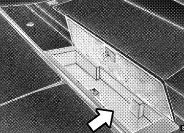
VIDEO ENTERTAINMENT SYSTEM (SALES CODE XRV) — IF EQUIPPED The optional VES™ (Video Entertainment System) con- sists of a DVD player and LCD (liquid crystal display) screen, a battery-powered remote control, and two head- sets. The DVD player is mounted in the rear of the center console storage bin, and is concealed by a door that lifts up for access. Refer to your VES™ User’s Manual for detailed operating instructions.
DVD Player Location
The LCD screen is located on the headliner behind the front seats.
UNDERSTANDING YOUR INSTRUMENT PANEL 215
Lowering the DVD Screen
Remote Control Location
216 UNDERSTANDING YOUR INSTRUMENT PANEL
SATELLITE RADIO — IF EQUIPPED Satellite radio uses direct satellite to receiver broadcast- ing technology to provide clear digital sound, coast to coast. The subscription service provider is Sirius™ Satel- lite Radio. This service offers over 100 channels of music, sports, news, entertainment, and programming for chil- dren, directly from its satellites and broadcasting studios. System Activation To activate your Sirius Satellite Radio service, call the toll-free number 888-539-7474, or visit the Sirius web site at www.sirius.com. Please have the following informa- tion available when activating your system: 1. The Electronic Serial Number/Sirius Identification Number (ESN/SID). 2. Credit card information. 3. Your Vehicle Identification Number.
Electronic Serial Number/Sirius Identification Number (ESN/SID) The Electronic Serial Number/Sirius Identification Num- ber is needed to activate your Sirius Satellite Radio system. To access the ESN/SID, refer to the following steps: ESN/SID Access with REC Radios Refer to the “Navigation User’s Manual” for details on satellite radio operation. ESN/SID Access with RAQ Radios With the ignition switch in the ACCESSORY position and the radio OFF, press the CD Eject and TIME buttons simultaneously for 3 seconds. All twelve ESN/SID num- bers will be displayed. The radio will exit the ESN/SID mode when any other button is pushed, the ignition is turned OFF, or 5 minutes has passed since any button was pushed.
Selecting Satellite Mode in RAQ Radios Press the MODE button repeatedly until the word ⬙SIRIUS⬙ appears in the display. These radios will also display the following: • After 3 seconds, the current channel name and channel • The current program type and channel number will • The current channel number will then be displayed
number will be displayed for 5 seconds.
then be displayed for 5 seconds.
until an action occurs.
A CD may remain in the radio while in the Satellite radio mode.
UNDERSTANDING YOUR INSTRUMENT PANEL 217
Selecting a Channel Press and release the SEEK or TUNE buttons to search for the next channel. Press the top of the button to search up and the bottom of the button to search down. Holding the TUNE button causes the radio to bypass channels until the button is released. Press and release the SCAN button (if equipped) to automatically change channels every 7 seconds. The radio will pause on each channel for 7 seconds before moving on to the next channel. The word ⬙SCAN⬙ will appear in the display between each channel change. Press the SCAN button a second time to stop the search. NOTE: Channels that may contain objectionable content can be blocked. Contact Sirius Customer Care at 888-539- 7474 to discuss options for channel blocking or unblock- ing. Please have your ESN/SID information available.
218 UNDERSTANDING YOUR INSTRUMENT PANEL
Storing and Selecting Pre-Set Channels In addition to the 10 AM and 10 FM pre-set stations, you may also commit 10 satellite stations to push button memory. These satellite channel pre-set stations will not erase any AM or FM pre-set memory stations. Follow the memory pre-set procedures that apply to your radio. Using the PTY (Program Type) Button — If Equipped Follow the PTY button instructions that apply to your radio. PTY Button ⴖSCANⴖ When the desired program type is obtained, press the ⬙SCAN⬙ button within five seconds. The radio will play 7
seconds of the selected channel before moving to the next channel of the selected program type. Press the ⬙SCAN⬙ button a second time to stop the search.NOTE: Pressing the ⬙SEEK⬙ or ⬙SCAN⬙ button while performing a music type scan will change the channel by one and stop the search. Pressing a pre-set memory button during a music type scan, will call up the memory channel and stop the search. PTY Button ⴖSEEKⴖ When the desired program is obtained, press the ⬙SEEK⬙ button within five seconds. The channel will change to the next channel that matches the program type selected. Satellite Antenna To ensure optimum reception on vehicles available with a luggage rack, do not place items on the roof around the rooftop antenna location. Metal objects placed within the line of sight of the antenna will cause decreased perfor- mance. Larger luggage items should be placed as far forward as possible. Do not place items directly on or above the antenna.
structure or under a physical obstacle.
Reception Quality Satellite reception may be interrupted due to one of the following reasons. • The vehicle is parked in an underground parking • Dense tree coverage may interrupt reception. • Driving under wide bridges or along tall buildings can • Placing objects over or too close to the antenna can
cause intermittent reception.
cause signal blockage.
REMOTE SOUND SYSTEM CONTROLS The remote sound system controls are located on the rear surface of the steering wheel. Reach behind the wheel to access the switches.
UNDERSTANDING YOUR INSTRUMENT PANEL 219
The right hand control is a rocker type switch with a push-button in the center and controls the volume and mode of the sound system. Pressing the top of the rocker switch will increase the volume and pressing the bottom of the rocker switch will decrease the volume.
220 UNDERSTANDING YOUR INSTRUMENT PANEL
Pressing the center button will make the radio switch between the various modes available (AM/FM/TAPE/ CD, Etc.). The left hand control is a rocker type switch with a push-button in the center. The function of the left hand control is different depending on which mode you are in. The following describes the left hand control operation in each mode. Radio Operation Pressing the top of the switch will “Seek” up for the next listenable station and pressing the bottom of the switch will “Seek” down for the next listenable station. The button located in the center of the left hand control will tune to the next preset station that you have pro- grammed in the radio preset push-button.
CD Player Pressing the top of the switch once will go to the next track on the CD. Pressing the bottom of the switch once will go to the beginning of the current track or to the beginning of the previous track if it is within one second after the current track begins to play. If you press the switch up or down twice it plays the second track, three times, it will play the third, etc. The center button on the left side rocker switch has no function for a single disc CD player. However, when a multiple disc CD player is equipped on the vehicle, the center button will select the next available CD in the player.
UNDERSTANDING YOUR INSTRUMENT PANEL 221
RADIO OPERATION AND CELLULAR PHONES Under certain conditions, the cellular phone being On in your vehicle can cause erratic or noisy performance from your radio. This condition may be lessened or eliminated by relocating the cellular phone antenna. This condition is not harmful to the radio. If your radio performance does not satisfactorily “clear” by the repositioning of the antenna, it is recommended that the radio volume be turned down or off during cellular phone operation.
CD/DVD DISC MAINTENANCE To keep the CD/DVD discs in good condition, take the following precautions: 1. Handle the disc by its edge; avoid touching the surface. 2. If the disc is stained, clean the surface with a soft cloth, wiping from center to edge. 3. Do not apply paper, paper CD labels, or tape to the disc; avoid scratching the disc. 4. Do not use solvents such as benzine, thinner, cleaners, or antistatic sprays. 5. Store the disc in its case after playing. 6. Do not expose the disc to direct sunlight. 7. Do not store the disc where temperatures may become too high.
222 UNDERSTANDING YOUR INSTRUMENT PANEL
CLIMATE CONTROLS
Automatic Temperature Control The Infrared Dual-Zone Climate Control System auto- matically maintains the interior comfort level desired by the driver and passenger. This is accomplished by a dual sun-sensor in the top of the instrument panel, and an infrared sensor located in the face of the control unit. There are also various sensors monitored by this system which take account for vehicle speed, A/C pressure, outside temperature, and engine cooling temperature. The infrared sensor independently measures the surface temperature of the driver and passenger. Based on the sensor input, the system automatically adjusts the air flow temperature, the air flow volume, and amount of outside air recirculation. This maintains a comfortable temperature even under changing conditions.
Automatic Temperature Controls
NOTE: The numbers on the temperature dial represent a comfort setting when the Mode knob is set to Auto, and not the actual air temperature. Operation of the system is quite simple. Begin by turning the right mode knob to AUTO, and place the blower control (left knob) to either LO AUTO or HI AUTO. The
LO AUTO position should be used for front seat occu- pants only. The HI AUTO position should be used when more air flow is desired, or when rear seat occupants are present. Dial in the comfort setting you would like the system to maintain by rotating the driver’s or passenger’s control knob. Once the comfort level is selected the system will maintain that level automatically using the heating system. Should the desired comfort level require air conditioning, the system will automatically make the adjustment. You will experience the greatest efficiency by simply allowing the system to function automatically. Selecting the OFF position on the fan control stops the system completely. NOTE: The temperature setting can be adjusted at any time without affecting automatic control operation. How- ever, if the driver and/or passenger temperature knobs are set to the full hot or full cold positions, the air
UNDERSTANDING YOUR INSTRUMENT PANEL 223
temperature out of the ducts will be full hot or full cold respectively. With the temperature setting in these posi- tions, the system does not attempt automatic comfort control.
The air conditioning in this system is automatic. Pressing this button while in AUTO mode will cause the LED to flash three times and remain off. This indicates that the system is in AUTO and requesting the air conditioning is not necessary.
The system will automatically control recircu- lation. However, pressing this button will tem- porarily put the system in recirculation mode. This can be used when outside conditions such as smoke, odors, dust, or high humidity are present. This will cause the LED to illuminate.
224 UNDERSTANDING YOUR INSTRUMENT PANEL
NOTE: • The surface of the climate control panel, and the top center of the instrument panel should be kept free of debris due to the climate control sensor’s location. Mud on the windshield may also cause poor operation of this system. • To provide you with maximum comfort in the auto- matic mode, during cold start-ups the blower fan will remain off until the engine warms up. However, the fan will engage immediately if the defrost mode is selected or if you manually select a blower speed. • Under certain conditions (after the vehicle is turned off) the climate control system may recalibrate and a noise may be heard for 20 seconds. This is part of normal operation. • Most of the time, when in Automatic operation, you can temporarily put the system into recirculation mode by pressing the Recirc button. However, under
certain conditions in automatic the system is blowing air out of the defrost vents. When these conditions are present and the Recirc button is pressed the indicator will flash and remain off. This tells you that you are unable to go into recirculation mode at this time. If you would like to go to Recirculation mode, you must first move your mode knob to panel, panel/floor or floor, then hit the Recirc button. This feature will reduce the possibility of window fogging.
Manual Operation This system offers a full complement of manual override features which consist of Blower Preferred Automatic, Mode Preferred Automatic with Manual Air Temperature Control and Manual. This means the customer can over- ride the blower, mode and disable automatic temperature control completely. NOTE: Please read the Automatic Temperature Control Operation Chart below for details.
UNDERSTANDING YOUR INSTRUMENT PANEL 225
226 UNDERSTANDING YOUR INSTRUMENT PANEL
NOTE: Regardless of the type of operation, when a temperature knob is set to the full clockwise or full counterclockwise position, the system will deliver full hot or full cold air out of the ducts, respectively. The operator can override the AUTO mode setting and select the direction of the air by rotating the right mode knob to one of the following positions. When the Mode is set to any position other than AUTO, the automatic control of air temperature is disabled. The user must adjust the temperature knobs to obtain the desired tem- perature. • Defrost
Air is directed to the windshield through the outlets at the base of the windshield. Air is also directed to the front door windows through the side window demister grilles. Some airflow is delivered to the floor while in defrost so that comfort can be maintained.
NOTE: The defrost mode is not automatically selected. It must be manually selected, when desired. • Defrost/Floor
Air flows through the front and rear floor outlets and the outlets at the base of the windshield. Air is also directed to the front door windows through the side window demister grilles. Some air- flow is delivered to the floor while in defrost so that comfort can be maintained.
• Floor
• Bi-Level
Air flows through the floor outlets located under the instrument panel and into the rear seating area through vents under the front seats. Some airflow is delivered to defrost while in floor mode, so that comfort can be maintained.
Air flows both through the outlets located in the instrument panel and those located on the floor.
Air flows through the registers in the back of the center console, and under the front seats to the rear seat passengers. These registers can be closed to block airflow. The center console outlets deliver conditioned air while the floor outlets deliver heated air.
• Panel
Air flows through the outlets located in the in- strument panel. Air flows through the registers in the back of the center console to the rear seat passen- gers. These registers can be closed to block airflow.
Depress this button to turn on and off the air conditioning during manual operation only. Con- ditioned outside air is then directed through the outlets selected on the mode control dial. The button includes an LED that illuminates when manual operation is selected. NOTE: To manually control the air conditioning the mode selector must be moved out of the AUTO position.
UNDERSTANDING YOUR INSTRUMENT PANEL 227
and the heated side mirrors
Press this button to turn on the rear window defroster (if equipped). An LED in the button will illuminate indicat- ing that the rear window defroster is ON. The defroster automatically turns off after approximately 10 minutes of operation for the first push of the button, and will turn off after approximately 5 minutes for the second push of the button.
CAUTION!
To avoid damaging the electrical conductors of the rear window defroster, do not use scrapers, sharp instruments, or abrasive window cleaners on the interior surface of the window. Labels can be peeled off after soaking with warm water.
228 UNDERSTANDING YOUR INSTRUMENT PANEL
This button can be used to block out smoke, odors, dust, high humidity, or if rapid cooling is desired. The recirculation mode should only be used temporarily. The button includes an LED that illuminates, which indicates that the recircula- tion mode is active. You may use this feature separately. NOTE: Extended use of recirculation may cause the windows to fog. If the interior of the windows begins to fog, press the “Recirculate” icon button to return to outside air. Some temp./humidity conditions will cause captured interior air to condense on windows and ham- per visibility. For this reason, the system will not allow “Recirculate” to be selected while in the defrost or defrost/floor modes. Attempting to use the recirculation while in these modes will cause the LED in the button to blink and then turn off.
Summer Operation The engine cooling system in air conditioned vehicles must be protected with a high-quality antifreeze coolant to provide proper corrosion protection and to protect against engine overheating. A 50% solution of ethylene glycol antifreeze coolant in water is recommended. Refer to “Maintenance Procedures” in Section 7 of this manual for proper coolant selection. Winter Operation Use of the air Recirculation mode during winter months is not recommended because it may cause window fogging. NOTE: Refer to the “Operating Tips” chart (for Manual A/C Control) in this section for suggested control set- tings in different weather conditions.
UNDERSTANDING YOUR INSTRUMENT PANEL 229
Outside Air Intake Make sure the air intake, located directly in front of the windshield, is free of obstructions such as leaves. Leaves collected in the air intake may reduce airflow and if they enter the plenum they could plug the water drains. In winter months make sure the air intake is clear of ice, slush and snow.
Vacation Storage Anytime you store your vehicle, or keep it out of service (i.e. vacation) for two weeks or more, run the air condi- tioning system at idle for about five minutes in the fresh air and high blower setting. This will insure adequate system lubrication to minimize the possibility of com- pressor damage when the system is started again. Window Fogging Interior fogging on the windshield can be quickly re- moved by turning the mode selector to Defrost, and turning on the high blower. The Defrost/Floor mode can be used to maintain a clear windshield and provide sufficient heating. If side window fogging becomes a problem increase blower speed. Vehicle windows tend to fog on the inside in mild but rainy or humid weather. NOTE: Recirculate without A/C should not be used for long periods as fogging may occur.
STARTING AND OPERATING
CONTENTS
䡵 Starting Procedures . . . . . . . . . . . . . . . . . . . . . 234
▫ Normal Starting . . . . . . . . . . . . . . . . . . . . . . 234
▫ Extreme Cold Weather (Below –20°F (–29°C) . . 235
▫ If Engine Fails To Start . . . . . . . . . . . . . . . . . 235
▫ After Starting . . . . . . . . . . . . . . . . . . . . . . . . 236
䡵 Transmission Shifting . . . . . . . . . . . . . . . . . . . . 236
▫ 5–Speed Automatic Transmission . . . . . . . . . . 236
▫ Gear Ranges . . . . . . . . . . . . . . . . . . . . . . . . . 237
▫ Rocking The Vehicle . . . . . . . . . . . . . . . . . . . 238䡵 AutoStick . . . . . . . . . . . . . . . . . . . . . . . . . . . . 239
▫ AutoStick Operation . . . . . . . . . . . . . . . . . . . 240
▫ AutoStick General Information . . . . . . . . . . . . 241
䡵 Parking Brake . . . . . . . . . . . . . . . . . . . . . . . . . 241
䡵 Anti-Lock Brake System . . . . . . . . . . . . . . . . . . 243
䡵 Power Steering . . . . . . . . . . . . . . . . . . . . . . . . 246
䡵 Tire Safety Information . . . . . . . . . . . . . . . . . . . 247
▫ Tire Markings . . . . . . . . . . . . . . . . . . . . . . . . 247
▫ Tire Identification Number (TIN) . . . . . . . . . . 251232 STARTING AND OPERATING
▫ Tire Loading And Tire Pressure . . . . . . . . . . . 252
䡵 Tires — General Information . . . . . . . . . . . . . . . 256
▫ Run Flat Tires . . . . . . . . . . . . . . . . . . . . . . . . 256
▫ Tire Pressure . . . . . . . . . . . . . . . . . . . . . . . . . 257
▫ Tire Inflation Pressures . . . . . . . . . . . . . . . . . 258
▫ Tire Pressures For High Speed Operation . . . . 260
▫ Radial-Ply Tires . . . . . . . . . . . . . . . . . . . . . . 261
▫ Tire Spinning . . . . . . . . . . . . . . . . . . . . . . . . 261
▫ Tread Wear Indicators . . . . . . . . . . . . . . . . . . 262
▫ Life Of Tire . . . . . . . . . . . . . . . . . . . . . . . . . 262
▫ Replacement Tires . . . . . . . . . . . . . . . . . . . . . 263
▫ Alignment And Balance . . . . . . . . . . . . . . . . . 264
. . . . . . . . 265䡵 Tire Pressure Monitor System (TPMS)
▫ Premium System . . . . . . . . . . . . . . . . . . . . . . 265
▫ General Information . . . . . . . . . . . . . . . . . . . 268
䡵 Tire Rotation Recommendations . . . . . . . . . . . . 268
䡵 Fuel Requirements . . . . . . . . . . . . . . . . . . . . . . 268
▫ Spark Knock . . . . . . . . . . . . . . . . . . . . . . . . . 268
▫ Reformulated Gasoline . . . . . . . . . . . . . . . . . 269
▫ Gasoline/Oxygenate Blends . . . . . . . . . . . . . . 269
▫ MMT In Gasoline . . . . . . . . . . . . . . . . . . . . . 270
▫ Materials Added To Fuel . . . . . . . . . . . . . . . . 270
▫ Fuel System Cautions . . . . . . . . . . . . . . . . . . 270
▫ Carbon Monoxide Warnings . . . . . . . . . . . . . . 271
䡵 Fuel Tank Filler Cap (Gas Cap) . . . . . . . . . . . . . 272
▫ Loose Fuel Filler Cap Message . . . . . . . . . . . . 273䡵 Trailer Towing . . . . . . . . . . . . . . . . . . . . . . . . . 274
▫ Common Towing Definitions . . . . . . . . . . . . . 275
▫ Trailer Hitch Classification . . . . . . . . . . . . . . . 277
▫ Trailer Towing Weights(Maximum Trailer Weight Ratings) . . . . . . . . . 278
STARTING AND OPERATING 233
▫ Trailer And Tongue Weight . . . . . . . . . . . . . . 278
▫ Towing Requirements . . . . . . . . . . . . . . . . . . 280
▫ Towing Tips . . . . . . . . . . . . . . . . . . . . . . . . . 284
䡵 Recreational Towing (Behind Motorhome, Etc.) . . 285234 STARTING AND OPERATING
STARTING PROCEDURES Before starting your vehicle, adjust your seat, adjust both inside and outside mirrors, and fasten your seat belts.
WARNING!
Do not leave children or animals inside parked vehicles in hot weather. Interior heat build up may cause serious injury or death.
The gear selector must be in the N (Neutral) or P (Park) position before you can start the engine. Apply the brakes before shifting to any driving gear. Normal Starting Normal starting of either a cold or a warm engine is obtained without pumping or depressing the accelerator pedal. Turn the key to the START position and release when the engine starts. If the engine fails to start within
10 seconds, turn the key to the OFF position, wait 5
seconds, then repeat the normal starting procedure.Ignition Key Positions
WARNING!
Never pour fuel or other flammable liquids into the throttle body air inlet opening in an attempt to start the vehicle. This could result in a flash fire causing serious personal injury.
Extreme Cold Weather (below –20°F (–29°C) To insure reliable starting at these temperatures, use of an externally powered electric engine block heater (available from your authorized dealer) is recommended. If Engine Fails to Start If the engine fails to start after you have followed the “Normal Starting” or “Extreme Cold Weather” proce- dures, it may be flooded. Push the accelerator pedal all the way to the floor and hold it there while cranking the engine. This should clear any excess fuel in case the engine is flooded.
STARTING AND OPERATING 235
NOTE: To prevent damage to the starter, do not crank the engine for more than 15 seconds at a time. Wait 10 to 15 seconds before trying again. If the engine has been flooded, it may start to run, but not have enough power to continue running when the key is released. If this occurs, continue cranking with the accel- erator pedal pushed all the way to the floor. Release the accelerator pedal and the key once the engine is running smoothly. If the engine shows no sign of starting after two 15– second periods of cranking with the accelerator pedal held to the floor, the “Normal Starting” or “Extreme Cold Weather” procedures should be repeated.
236 STARTING AND OPERATING
After Starting The idle speed will automatically decrease as the engine warms up.
vehicle, may be somewhat abrupt. This is a normal condition, and precision shifts will develop within a few hundred miles.
CAUTION!
Long periods of engine idling, especially at high engine speeds can cause excessive exhaust tempera- tures which can damage your vehicle. Do not leave your vehicle unattended with the engine running.
TRANSMISSION SHIFTING
5–Speed Automatic Transmission The electronically controlled transmission provides a precise shift schedule. The transmission electronics are self-calibrating; therefore, the first few shifts on a new
Automatic Shift Controls
WARNING!
Gear Ranges
STARTING AND OPERATING 237
It is dangerous to shift the selector lever out of P (Park) or N (Neutral) if the engine speed is higher than idle speed. If your foot is not firmly on the brake pedal, the vehicle could accelerate quickly forward or in reverse. You could lose control of the vehicle and hit someone or something. Only shift into gear when the engine is idling normally and when your foot is firmly on the brake pedal.
Brake Transmission Shift Interlock System This vehicle is equipped with a brake transmission shift interlock system (BTSI) that holds the gearshift lever in the P (Park) position when the ignition switch is in the LOCK position. To move the gear selector lever out of the P (Park) position, the ignition switch must be turned to the ON position, and the brake pedal must be depressed.
NOTE: After selecting any gear range, wait a moment to allow the selected gear to engage before accelerating. This is especially important when the engine is cold. If there is a need to restart the engine be sure to cycle the key to the LOCK position before restarting. Transmission gear engagement may be delayed after restarting the engine if the key is not cycled to the LOCK position first. P (Park) Supplements the parking brake by locking the transmis- sion. The engine can be started in this range. Never use P (Park) while the vehicle is in motion. Apply the parking brake when leaving the vehicle in this range.
238 STARTING AND OPERATING
WARNING!
Unintended movement of a vehicle could injure those in and near the vehicle. As with all vehicles, you should never exit a vehicle while the engine is running. Before exiting a vehicle, you should apply the park brake, shift the transmission into P (Park), and remove the key from the ignition. Once the key is removed from the ignition the transmission shift lever is locked in the P (Park) position, securing the vehicle against unwanted movement. Furthermore, you should never leave children unattended inside a vehicle.
R (Reverse) Shift into this range only after the vehicle has come to a complete stop.
N (Neutral) No power is transmitted from the engine to the drive axle. When the brakes are released, the vehicle can roll freely. Do not engage in N (Neutral) position while driving except to coast when the vehicle is in danger of skidding (e.g., on icy roads). D (Drive) The transmission automatically upshifts through fifth gear. The D (Drive) position provides optimum driving characteristics under all normal operating conditions. For additional shifting information, refer to “Autostick” later in this section. Rocking the Vehicle If the vehicle becomes stuck in snow, sand, or mud, it can often be moved by a rocking motion. Move the gear selector rhythmically between D (Drive) and R (Reverse), while applying slight pressure to the accelerator.
NOTE: The Electronic Stability Program (ESP) and Traction Control (if equipped) should be turned OFF before attempting to rock the vehicle. Refer to “Electronic Brake Control System” in Section 3 of this manual. The least amount of accelerator pedal pressure to main- tain the rocking motion without spinning the wheels or racing the engine is most effective. Racing the engine or spinning the wheels, due to the frustration of not freeing the vehicle, may lead to transmission overheating and failure. Allow the engine to idle with the transmission selector in N (Neutral) for at least one minute after every five rocking-motion cycles. This will minimize overheat- ing and reduce the risk of transmission failure during prolonged efforts to free a stuck vehicle.
STARTING AND OPERATING 239
CAUTION!
When “rocking” a stuck vehicle by moving between “First” and R (Reverse), do not spin the wheels faster than 15 mph (24 km/h), or drivetrain damage may result.
AUTOSTICK Autostick is a driver-interactive transmission that offers manual gear shifting capability to provide the driver with more control. Autostick allows the driver to increase engine braking ability, control upshift and downshift points, and enhance the driving experience. This system