- 2008 Jeep Compass Owners Manuals
- Jeep Compass Owners Manuals
- 2011 Jeep Compass Owners Manuals
- Jeep Compass Owners Manuals
- 2007 Jeep Compass Owners Manuals
- Jeep Compass Owners Manuals
- 2013 Jeep Compass Owners Manuals
- Jeep Compass Owners Manuals
- 2009 Jeep Compass Owners Manuals
- Jeep Compass Owners Manuals
- 2012 Jeep Compass Owners Manuals
- Jeep Compass Owners Manuals
- 2010 Jeep Compass Owners Manuals
- Jeep Compass Owners Manuals
- Download PDF Manual
-
To use the washer, pull the control lever toward you and hold while spray is desired. If the lever is pulled while in the delay range, the wiper will operate in low speed for two wipe cycles after the lever is released, and then resume the intermittent interval previously selected.
Off-Road Light Switch
120 UNDERSTANDING THE FEATURES OF YOUR VEHICLE
If the lever is pulled while in the OFF position, the wipers will operate for two wipe cycles, then turn OFF.
Mist Feature Push down on the wiper control lever to activate a single wipe to clear the windshield of road mist or spray from a passing vehicle. As long as the lever is held down, the wipers will continue to operate.
Rear Washer control
Mist Control
CAUTION!
In cold weather, always turn off the wiper switch and allow the wipers to return to the park position before turning off the engine. If the wiper switch is left on and the wipers freeze to the windshield, damage to the wiper motor may occur when the vehicle is restarted.
UNDERSTANDING THE FEATURES OF YOUR VEHICLE 121
Windshield Wiper Operation Turn the end of the handle to select the desired wiper speed.
Wiper Control
122 UNDERSTANDING THE FEATURES OF YOUR VEHICLE
Intermittent Wiper System Use the intermittent wiper when weather conditions make a single wiping cycle, with a variable pause be- tween cycles, desirable. Select the delay interval by turning the end of the lever. Rotate the knob upward (clockwise) to decrease the delay time and downward (counterclockwise) to increase the delay time. The delay can be regulated from a maximum of approximately 18
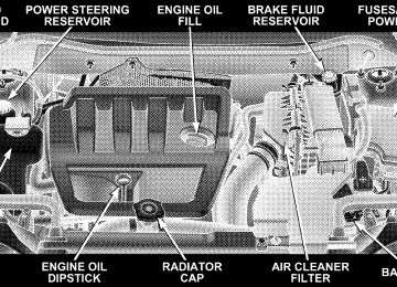
seconds between cycles, to a cycle every second. Adding Washer Fluid The fluid reservoir for the windshield washers and the rear window washer (If Equipped) is shared. It is located in the front of the engine compartment on the passenger side and should be checked for fluid level at regular intervals. Fill the reservoir with windshield washer sol- vent (not radiator antifreeze) and operate the system for a few seconds to flush out the residual water.TILT STEERING COLUMN To tilt the steering column, push down on the lever below the turn signal control lever. With one hand firmly on the wheel, move the steering column up or down as desired. Push the lever back up to lock the column firmly in place.
Tilting Steering Column Control
WARNING!
Tilting the steering column while the vehicle is moving is dangerous. Without a stable steering col- umn, you could lose control of the vehicle and have an accident. Adjust the column only while the ve- hicle is stopped. Be sure it is locked before driving.
ELECTRONIC SPEED CONTROL — IF EQUIPPED When engaged, this device takes over the accelerator operation at speeds greater than 25 mph (40 km/h). The speed control lever is located on the right side of the steering wheel.
UNDERSTANDING THE FEATURES OF YOUR VEHICLE 123
Speed Control Location
To Activate Push the ON/OFF button. The CRUISE indicator in the instrument cluster will illuminate. To turn the system OFF, push the ON/OFF button a second time. The CRUISE indicator will turn off. The system should be turned OFF when not in use.
124 UNDERSTANDING THE FEATURES OF YOUR VEHICLE
WARNING!
Leaving the Electronic Speed Control system on when not in use is dangerous. You could accidentally set the system or cause it to go faster than you want. You could lose control and have an accident. Always leave the system OFF when you are not using it.
To Set At A Desired Speed When the vehicle has reached the desired speed, press down on the lever and release. Release the accelerator and the vehicle will operate at the selected speed. NOTE: The vehicle should be traveling at a steady speed and on level ground before pressing the SET lever.
To Deactivate A soft tap on the brake pedal, pulling the speed control lever towards you “CANCEL”, or normal brake or clutch pressure while slowing the vehicle will deactivate speed control without erasing the set speed memory. Pressing the ON/OFF button or turning off the ignition switch erases the set speed memory. To Resume Speed To resume a previously set speed, push the “RESUME ACCEL” lever up and release. Resume can be used at any speed above 20 mph (32 km/h). To Vary The Speed Setting When the speed control is ON, speed can be increased by pushing up and holding “RESUME ACCEL”. Release the lever when the desired speed is reached, and the new speed will be set.
Tapping “RESUME ACCEL” once will result in a 1 mph (1.6 km/h) speed increase. Each time the lever is tapped, speed increases so that tapping the lever three times will increase speed by 3 mph (4.8 km/h), etc. To decrease speed while speed control is ON, push down and hold “SET DECEL”. Release the lever when the desired speed is reached, and the new speed will be set. Tapping the “SET DECEL” button once will result in a 1
mph (1.6 km/h) speed decrease. Each time the button is tapped, speed decreases. Manual Transaxle Depressing the clutch pedal will disengage the speed control. A slight increase in engine RPM before the speed control disengages is normal.UNDERSTANDING THE FEATURES OF YOUR VEHICLE 125
Vehicles equipped with manual transaxles may need to be shifted into a lower gear to climb hills without speed loss.
WARNING!
Speed Control can be dangerous where the system can’t maintain a constant speed. Your vehicle could go too fast for the conditions, and you could lose control. An accident could be the result. Don’t use Speed Control in heavy traffic or on roads that are winding, icy, snow-covered, or slippery.
To Accelerate For Passing Depress the accelerator as you would normally. When the pedal is released, the vehicle will return to the set speed.
126 UNDERSTANDING THE FEATURES OF YOUR VEHICLE
Using Speed Control On Hills NOTE: The speed control system maintains speed up and down hills. A slight speed change on moderate hills is normal. On steep hills a greater speed loss or gain may occur so it may be preferable to drive without speed control.
ANTI-LOCK BRAKE SYSTEM (ABS) – IF EQUIPPED This system aids the driver in maintaining vehicle control under adverse braking conditions. The system controls hydraulic brake pressure to prevent wheel lockup and help avoid skidding on slippery surfaces during braking. NOTE: ABS improves steering control of the vehicle during hard braking maneuvers.
WARNING!
† Anti-lock system (ABS) cannot prevent the natural laws of physics from acting on the vehicle, nor can it increase braking or steering efficiency beyond that afforded by the condition of the vehicle brakes and tires or the traction afforded. † The ABS cannot prevent accidents,
including those resulting from excessive speed in turns, following another vehicle too closely, or hydro- planing. Only a safe, attentive, and skillful driver can prevent accidents. † The capabilities of an ABS equipped vehicle must never be exploited in a reckless or dangerous manner which could jeopardize the user’s safety or the safety of others.
ELECTRONIC BRAKE CONTROL SYSTEM – ABS/TCS/BAS/ERM/ESP Your vehicle may be equipped with an optional ad- vanced electronic brake control system that includes Anti-Lock Brake System (ABS), Traction Control System (TCS), Brake Assist System ( BAS), Electronic Roll Miti- gation (ERM) and Electronic Stability Program (ESP). All systems work together to enhance vehicle stability and control in various driving conditions and are commonly referred to as ESP. Anti-Lock Brake System – (ABS) This system aids the driver in maintaining vehicle control under adverse braking conditions. The system controls hydraulic brake pressure to prevent wheel lock-up and help avoid skidding on slippery surfaces during braking. Refer to “Anti-Lock Brake System” in this Section of the manual for more information about ABS.
UNDERSTANDING THE FEATURES OF YOUR VEHICLE 127
Traction Control System (TCS) This system monitors the amount of wheel spin of each of the driven wheels. If wheel spin is detected, brake pressure is applied to the slipping wheel(s) and engine power is reduced to provide enhanced acceleration and stability. A feature of the TCS system functions similar to a limited slip differential and controls the wheel spin across a driven axle. If one wheel on a driven axle is spinning faster than the other, the system will apply the brake of the spinning wheel. This will allow more engine torque to be applied to the wheel that is not spinning. This feature remains active even if TCS and ESP are in either the “Partial Off” or “ESP Off” modes. Refer to “Electronic Stability Program (ESP)” in this Section of this manual.
128 UNDERSTANDING THE FEATURES OF YOUR VEHICLE
Brake Assist System (BAS) The BAS is designed to optimize the vehicle’s braking capability during emergency braking maneuvers. The system detects an emergency braking situation by sens- ing the rate and amount of brake application and then applies optimum pressure to the brakes. This can help reduce braking distances. The BAS complements the Anti-Lock Brake System (ABS). Applying the brakes very quickly results in the best BAS assistance. To receive the benefit of the system, you must apply continuous brak- ing pressure during the stopping sequence. Do not reduce brake pedal pressure unless braking is no longer desired. Once the brake pedal is released, the BAS is deactivated.
WARNING!
† BAS cannot prevent the natural laws of physics from acting on the vehicle, nor can it increase braking efficiency beyond that afforded by the condition of the vehicle brakes and tires or the traction afforded.
† The BAS cannot prevent accidents,
including those resulting from excessive speed in turns, following another vehicle too closely, or hydro- planing. Only a safe, attentive, and skillful driver can prevent accidents. † The capabilities of a BAS-equipped vehicle must never be exploited in a reckless or dangerous manner which could jeopardize the user’s safety or the safety of others.
Electronic Roll Mitigation (ERM) This system anticipates the potential for wheel lift by monitoring the driver’s steering wheel input and the speed of the vehicle. When ERM determines that the rate of change of the steering wheel angle and vehicles speed are sufficient to potentially cause wheel lift, it applies the appropriate brake and may reduce engine power to lessen the chance that wheel lift will occur. ERM will only intervene during very severe or evasive driving maneu- vers. ERM can only reduce the chance of wheel lift occurring during severe or evasive driving maneuvers. It can not prevent wheel lift due to other factors such as road conditions, leaving the roadway or striking objects or other vehicles.
UNDERSTANDING THE FEATURES OF YOUR VEHICLE 129
WARNING!
Many factors, such as vehicle loading, road condi- tions and driving conditions, influence the chance that wheel lift or rollover may occur. ERM can not prevent all wheel lift or rollovers, especially those that involve leaving the roadway or striking objects or other vehicles. Only a safe, attentive, and skillful driver can prevent accidents. The capabilities of an ERM equipped vehicle must never be exploited in a reckless or dangerous manner which could jeopar- dize the user’s safety or the safety of others.
ESP/TCS Indicator Light The “ESP/TCS Indicator Light” located in the instrument cluster, starts to flash as soon as the tires lose traction and the ESP system becomes active. The “ESP/TCS Indicator Light” also flashes when TCS is active. If the “ESP/TCS Indicator Light” begins to flash during acceleration, ease up on the accelerator and apply as little throttle as possible. Be sure to adapt your speed and driving to the prevailing road conditions.
130 UNDERSTANDING THE FEATURES OF YOUR VEHICLE
ESP (Electronic Stability Program)
This system enhances directional control and stability of the vehicle under various driving conditions. ESP cor- rects for over/under steering of the vehicle by applying the brake of the appropriate wheel to assist in counter- acting the over/under steer condition. Engine power may also be reduced to help the vehicle maintain the desired path. ESP uses sensors in the vehicle to determine the vehicle path intended by the driver and compares it to the actual path of the vehicle. When the actual path does not match the intended path, ESP applies the brake of the appropriate wheel to assist in counteracting the oversteer or understeer condition † Oversteer - when the vehicle is turning more than † Understeer - when the vehicle is turning less than
appropriate for the steering wheel position.
appropriate for the steering wheel position.
WARNING!
† Electronic Stability Program (ESP) cannot prevent the natural laws of physics from acting on the vehicle, nor can it increase the traction afforded by prevailing road conditions. † ESP cannot prevent accidents, including those resulting from excessive speed in turns, driving on very slippery surfaces, or hydroplaning. Only a safe, attentive, and skillful driver can prevent accidents. † The capabilities of an ESP-equipped vehicle must never be exploited in a reckless or dangerous manner which could jeopardize the user’s safety or the safety of others.
UNDERSTANDING THE FEATURES OF YOUR VEHICLE 131
ESP 2WD Operating Modes All 2WD vehicles can choose the following ESP operating modes: ESP ON This is the normal operating mode for ESP. Whenever the vehicle is started the ESP system will be in this mode. This mode should be used for almost all driving situa- tions. ESP should only be turned to “Partial Off” or “ESP Off” for specific reasons as noted below. PARTIAL ESP This mode is entered by momentarily depressing the “ESP Control Switch”. When in “Partial Off” mode, the TCS portion of ESP, except for the “limited slip” feature described in the TCS section, has been disabled and the “ESP/TCS Indicator Light” will be illuminated. All other stability features of ESP function normally, with the exception of engine power reduction. This mode is intended to be used if the vehicle is in deep snow, sand or
132 UNDERSTANDING THE FEATURES OF YOUR VEHICLE
gravel conditions and more wheel spin than ESP would normally allow is required to gain traction. To turn ESP on again, momentarily depress the “ESP Control Switch”. This will restore the normal “ESP On” mode of operation.
WARNING!
In the Partial ESP mode, the engine torque reduction and stability features are desensitized. Therefore, the enhanced vehicle stability offered by ESP is unavailable.
NOTE: To improve the vehicle’s traction when driving with snow chains, or starting off in deep snow, sand or gravel, it may be desirable to switch to the “Partial Off” mode by pressing the ESP switch. Once the situation requiring ESP to be switched to the “Partial Off” mode is
overcome, turn ESP back on by momentarily depressing the “ESP Control Switch”. This may be done while the vehicle is in motion. ESP 4WD Operating Modes In addition to ESP ON and Partial ESP (described above in “ESP 2WD Operating Modes”), all 4WD equipped vehicles can also choose the following ESP operating mode: ESP OFF This mode is intended for off-highway or off-road use when ESP stability features could inhibit vehicle maneu- verability due to trail conditions. This mode is entered by depressing and holding the “ESP Control Switch” for 5
seconds when the vehicle is stopped and the engine is running. After 5 seconds, the “ESP/TCS Indicator Light” will illuminate and the “ESP Off” message will appear in the odometer. Press and release the trip odometer button located on the instrument cluster to clear this message.In this mode, ESP and TCS, except for the “limited slip” feature described in the TCS section, are turned off until the vehicle reaches a speed of 35 mph (56 km/h). At 35
mph (56 km/h) the normal ESP stability function returns with the exception of engine power reduction. TCS remains off. When the vehicle speed drops below 30 mph (48 km/h) the ESP system shuts off. ESP is off at low vehicle speeds so that it will not interfere with off-road driving but ESP function returns to provide the stability feature at speeds above 35 mph (56 km/h). The “ESP/ TCS Indicator Light” will always be illuminated when ESP is off.To turn ESP on again, momentarily depress the “ESP Control Switch”. This will restore the normal “ESP On” mode of operation.
UNDERSTANDING THE FEATURES OF YOUR VEHICLE 133
ESP/BAS Warning Light and ESP/TCS Indicator Light The malfunction indicator for the ESP is combined with the BAS indicator. The yellow “ESP/BAS Warning Lamp” and the yellow “ESP/TCS Indicator Light” in the instrument cluster both come on when the ignition switch is turned to the “ON” position. They should both go out with the engine running. If the “ESP/BAS Warn- ing Lamp” comes on continuously with the engine running, a malfunction has been detected in either the ESP or BAS system, or both. If this light remains on after several ignition cycles, and the vehicle has been driven several miles at speeds greater than 30 mph (48 km/h), see your authorized dealer as soon as possible to have the problem diagnosed and corrected.
134 UNDERSTANDING THE FEATURES OF YOUR VEHICLE
WARNING!
With the ESP switched off, the enhanced vehicle stability offered by ESP is unavailable. In an emer- gency evasive maneuver, the ESP system will not engage to assist in maintaining stability. “ESP Off” mode is intended for off-highway or off-road use, only.
NOTE: † The “ESP Indicator Light” and the “ESP/BAS Warning Light” come on momentarily each time the ignition switch is turned ON. † Each time the ignition is turned ON, the ESP System
will be ON even if it was turned off previously.
† The ESP Control System will make buzzing or clicking sounds when it is active. This is normal; the sounds will stop when ESP becomes inactive following the maneuver that caused the ESP activation.
GARAGE DOOR OPENER — IF EQUIPPED HomeLinkt replaces up to three remote controls (hand held transmitters) that operate devices such as garage door openers, motorized gates, lighting, or home security systems. The HomeLinkt unit operates off of your vehi- cle’s battery. NOTE: HomeLinkt is disabled when the Vehicle Theft Alarm is active.
WARNING!
WARNING!
UNDERSTANDING THE FEATURES OF YOUR VEHICLE 135
Your motorized door or gate will open and close while you are training the Universal Transceiver. Do not train the transceiver if people or pets are in the path of the door or gate. Only use this transceiver with a garage door opener that has a “stop and reverse” feature as required by federal safety stan- dards. This includes most garage door opener models manufactured after 1982. Do not use a garage door opener without these safety features. Call toll-free 1–800–355–3515
at www.HomeLink.com for safety information or assistance.Internet
the
on
or,
Vehicle exhaust contains carbon monoxide, a danger- ous gas. Do not run your vehicle in the garage while training the transceiver. Exhaust gas can cause seri- ous injury or death.
Programming HomeLinkT
Before You Begin If you have not trained any of the HomeLinkt buttons, erase all channels before you begin training. To do this, press and hold the two outside buttons for 20
seconds until the red indicator flashes. It is recommended that a new battery be placed in the hand-held transmitter of the device being programmed to HomeLinkt for more efficient training and accurate transmission of the radio-frequency signal.136 UNDERSTANDING THE FEATURES OF YOUR VEHICLE
Your vehicle should be parked outside of the garage when programming. 1. Turn the ignition switch to the ON/RUN position. 2. Hold the battery side of the hand-held transmitter away from the HomeLinkt button you wish to program. Place the hand-held transmitter 1–3 inches (3–8 cm) away from the HomeLinkt button you wish to program while keeping the indicator light in view. 3. Simultaneously press and hold both the chosen HomeLinkt button and the hand-held transmitter button until the HomeLinkt indicator changes from a slow to a rapidly blinking light, then release both the HomeLinkt and hand-held transmitter buttons. Watch for the HomeLinkt indicator to change flash rates. When it changes, it is programmed. It may take up to 30
seconds, or longer in rare cases. The garage door may open & close while you train.NOTE: † Some gate operators and garage door openers may require you to replace Step #3 with procedures noted in the “Gate Operator/Canadian Programming” section. † After training a HomeLinkt channel, if the garage door does not operate with HomeLinkt and the garage door opener was manufactured after 1995, the garage door opener may have rolling code. If so, proceed to the heading “Programming A Rolling Code System.” 4. Press and hold the just-trained HomeLinkt button and observe the indicator light. If the indicator light stays on constantly, programming is complete and the garage door (or device) should activate when the HomeLinkt button is pressed. If the indicator light blinks rapidly for two seconds, and then turns to a constant light, continue with program- ming for Rolling Code.
5. PROGRAMMING A ROLLING CODE SYSTEM At the garage door opener motor (in the garage), locate the “learn” or “training” button. This can usually be found where the hanging antenna wire is attached to the garage door opener motor (it is NOT the button normally used to open & close the door).
UNDERSTANDING THE FEATURES OF YOUR VEHICLE 137
1 — Garage Door Opener 2 — Training Button 6. Firmly press and release the “learn” or “training” button. The name and color of the button may vary by manufacturer. NOTE: There are 30 seconds in which to initiate the next step after the “Learn” button has been pressed.
138 UNDERSTANDING THE FEATURES OF YOUR VEHICLE
7. Return to the vehicle and press the programmed HomeLinkt button twice (holding the button for 2 sec- onds each time). If the device is plugged in and activates, programming is complete. If the device does not activate, press the button a third time (for 2 seconds) to complete the training. If you are have any problems, or require assistance, please call toll-free 1–800–355–3515 or, on the Internet at www.HomeLink.com for information or assistance. To program the remaining two HomeLinkt buttons, repeat each step for each remaining button. DO NOT erase the channels. Gate Operator/Canadian Programming Canadian radio-frequency laws require transmitter sig- nals to “time-out” (or quit) after several seconds of transmission – which may not be long enough for HomeLinkt to pick up the signal during programming.
Similar to this Canadian law, some U.S. gate operators are designed to “time-out” in the same manner. It may be helpful to unplug the device during the cycling process to prevent possible overheating of the garage door or gate motor. If you are having difficulties programming a garage door opener or a gate operator, replace “Programming HomeLink” Step 3 with the following: 3. Continue to press and hold the HomeLinkt button while you press and release - every two seconds (“cycle”) your hand-held transmitter until HomeLinkt has successfully accepted the frequency signal. The indicator light will flash slowly and then rapidly when fully trained. If you unplugged the device for training, plug it back in at this time. Then proceed with Step 4 under “Programming HomeLink.” earlier in this section.
UNDERSTANDING THE FEATURES OF YOUR VEHICLE 139
Security It is advised to erase all channels before you sell or turn in your vehicle. To do this, press and hold the two outside buttons for 20
seconds until the red indicator flashes. Note that all channels will be erased. Individual channels cannot be erased. The HomeLinkt Universal Transceiver is disabled when the Vehicle Theft Alarm is active.Using HomeLinkT To operate, simply press and release the programmed HomeLinkt button. Activation will now occur for the trained device (i.e. garage door opener, gate operator, security system, entry door lock, home/office lighting, etc. The hand-held transmitter of the device may also be used at any time. Reprogramming a Single HomeLinkT Button To re-program a channel trained, follow these steps: 1. Turn the ignition switch to the ON/RUN position. 2. Press and hold the desired HomeLinkt button until the indicator light begins to flash after 20 seconds. Do not release the button. 3. Without releasing the button, proceed with PRO- GRAMMING HOMELINK Step #2 and follow all remain- ing steps.
that has been previously
140 UNDERSTANDING THE FEATURES OF YOUR VEHICLE
Troubleshooting Tips If you are having trouble programming HomeLinkt, here are some of the most common solutions: † Replace the battery in the original transmitter. † Press the Learn Button on the Garage Door Opener to † Did you unplug the device for training, and remember
complete the training for Rolling Code.
to plug it back in?
If you are have any problems, or require assistance, please call toll-free 1–800–355–3515 or, on the Internet at www.HomeLink.com for information or assistance.
General Information This device complies with FCC rules part 15 and Industry Canada RSS-210. Operation is subject to the following two conditions: 1. This device may not cause harmful interference 2. This device must accept any interference that may be received including interference that may cause undesired operation NOTE: The transmitter has been tested and it complies with FCC and IC rules. Changes or modifications not expressly approved by the party responsible for compli- ance could void the user’s authority to operate the device. The term “IC:” before the certification/registration num- ber only signifies that Industry Canada technical specifi- cations were met.
POWER SUNROOF — IF EQUIPPED The power sunroof switch is located in the reading lamp.
Power Sunroof Switch
UNDERSTANDING THE FEATURES OF YOUR VEHICLE 141
WARNING!
† Never leave children in a vehicle, with the keys in the ignition switch. Occupants, particularly unat- tended children, can become entrapped by the power sunroof while operating the power sunroof switch. Such entrapment may result in serious injury or death. † In an accident, there is a greater risk of being thrown from a vehicle with an open sunroof. You could also be seriously injured or killed. Always fasten your seat belt properly and make sure all passengers are properly secured too. † Do not allow small children to operate the sun- roof. Never allow fingers or other body parts, or any object to project through the sunroof opening. Injury may result.
142 UNDERSTANDING THE FEATURES OF YOUR VEHICLE
Opening the Sunroof
Closing the Sunroof
Manual Mode To open the sunroof, press and hold the switch rearward to full open. Any release of the switch will stop the movement and the sunroof will remain in a partial open condition until the switch is pushed and held rearward again. Express Mode Press the switch rearward and release, and the sunroof will open automatically from any position. The sunroof will open fully, the stop automatically. This is called Express Open. During Express Open operation, any movement of the sunroof switch will stop the sunroof.
Manual Mode To close the sunroof, press and hold the switch in the forward position. Again, any release of the switch will stop the movement and the sunroof will remain in a partial close condition until the switch is pushed and held forward again. To ensure sunroof is fully closed, press and hold switch until sunroof has completely stopped moving. Express Mode Press the switch forward and release, and the sunroof will close automatically from any position. The sunroof will close fully and stop automatically. This is called Express Close. During Express Close operation, any movement of the switch will stop the sunroof.
Pinch Protect Feature This feature will detect an obstruction in the opening of the sunroof during Express Close operation. If an ob- struction in the path of the sunroof is detected, the sunroof will automatically retract. Next, press the switch forward and release to Express Close. Pinch Protect Override If a known obstruction (ice, debris, etc.) prevents closing, press the switch forward and hold for two seconds after the reversal occurs. This allows the sunroof to move towards the close position. NOTE: Pinch protection is disabled while the switch is pressed.
UNDERSTANDING THE FEATURES OF YOUR VEHICLE 143
Venting Sunroof – Express Press and hold the “V” button, and the sunroof will open to the vent position. This is called Express Vent, and will occur regardless of the sunroof position. During Express Vent operation, any movement of the switch will stop the sunroof. Sunshade Operation The sunshade can be opened manually. However, the sunshade will open automatically as the sunroof opens. NOTE: The sunshade cannot be closed if the sunroof is open. Wind Buffeting Wind buffeting can be described as the perception of pressure on the ears or a helicopter type sound in the ears. Your vehicle may exhibit wind buffeting with the windows down, or the sunroof (if equipped) in certain open or partially open positions. This is a normal occur- rence and can be minimized. If the buffeting occurs with
144 UNDERSTANDING THE FEATURES OF YOUR VEHICLE
the rear windows open, open the front and rear windows together to minimize the buffeting. If the buffeting occurs with the sunroof open, adjust the sunroof opening to minimize the buffeting or open any window. Sunroof Maintenance Use only a non-abrasive cleaner and a soft cloth to clean the glass panel. Ignition Off Operation
The sunroof will also operate up to 45 seconds after the ignition has been turned off. The sunroof operation will be canceled if either of the front doors are opened during the 45 second time period.
ELECTRICAL POWER OUTLETS — IF EQUIPPED There is a standard 12-Volt power outlet in the instru- ment panel and a 115 Volt (150 Watts Maximum) power outlet in the center console on certain models for added convenience. These outlets can power cell phones, elec- tronics and other low power devices. NOTE: Due to overload protection the inverter will shut down if the power rating is exceeded.
WARNING!
To Avoid Serious Injury or Death: † Do not use a 3 - Prong Adaptor. † Do not insert any objects into the receptacles. † Do not touch with wet hands. † Close the lid when not in use, and while driving † If this outlet is mishandled it may cause an electric
the vehicle
shock and failure.
UNDERSTANDING THE FEATURES OF YOUR VEHICLE 145
Power Outlet 12 Volts
146 UNDERSTANDING THE FEATURES OF YOUR VEHICLE
Power Outlet 115 Volts (150 Watt)
Electrical Outlet Use With Engine Off
CAUTION!
† Many accessories that can be plugged in draw power from the vehicle’s battery, even when not in use (i.e. cellular phones, etc.). Eventually, if plugged in long enough, the vehicle’s battery will discharge sufficiently to degrade battery life and/or prevent engine starting. † Accessories that draw higher power (i.e. coolers, vacuum cleaners, lights, etc.); will degrade the battery even more quickly. Only use these inter- mittently and with greater caution. † After the use of high power draw accessories, or long periods of the vehicle not being started (with accessories still plugged in), the vehicle must be driven a sufficient length of time to allow the generator to recharge the vehicle’s battery.
CONSOLE FEATURES
WARNING!
Do not operate this vehicle with the console compart- ment lid in the open position. Cell phones, music players, and other hand held electronic devices should be stowed while driving. Use of these devices while driving can cause an accident due to distrac- tion, resulting in death or injury.
The floor console’s sliding armrest moves forward 3
inches to accommodate shorter drivers. The armrest lid also includes a unique flip pocket for storing a phone or an MP3 player. The bin inside the console can hold up to 10 CD jewel cases or other items securely out of sight.UNDERSTANDING THE FEATURES OF YOUR VEHICLE 147
Floor Console
NOTE: The flip pocket and console lid features are intended to be used in the upright or open position only while the vehicle is parked. While driving, all handheld devices should be properly stowed, and the flip pocket and the console lid should be closed.
148 UNDERSTANDING THE FEATURES OF YOUR VEHICLE
CARGO AREA FEATURES
Cargo Light/Removable Self Recharging Flashlight – If Equipped The dual-function light is mounted in the headliner above the cargo area to illuminate the cargo area, and part of it snaps out of the bezel to serve as a flashlight when needed. The flashlight features two bright LED light bulbs and is powered by rechargeable lithium batteries when snapped back into place for convenience. To operate the flashlight, press the switch once for high, twice for low, and a third time to return to off.
Press and Release
UNDERSTANDING THE FEATURES OF YOUR VEHICLE 149
Removing Flashlight
Three Press Switch
Removable Load Floor The cargo area load floor is removable and can be washed with mild soap and water.
150 UNDERSTANDING THE FEATURES OF YOUR VEHICLE
Cargo Cover — If Equipped The cargo area trim panels include two notches for mounting the available cargo cover that accommodates the reclining rear seat.
WARNING!
In an accident a cargo cover loose in the vehicle could cause injury. It could fly around in a sudden stop and strike someone in the vehicle. Do not store the cargo cover on the cargo floor or in the passenger compart- ment. Remove the cover from the vehicle when taken from its mounting. Do not store in the vehicle.
Rear Cargo Area
Cargo Tie-Down Loops There are four D-rings tie-down loops in the lower trim for securing cargo.The tie-downs located on cargo area floor should be used to safely secure loads when vehicle is moving.
WARNING!
† Cargo tie-down Loops are not safe anchors for a child seat tether strap. In a sudden stop or collision a loop could pull loose and allow the child seat to come loose. A child could be badly injured. Use only the anchors provided for child seat tethers. † The weight and position of cargo and passengers can change the vehicle center of gravity and ve- hicle handling. To avoid loss of control resulting in personal injury, follow these guidelines for loading your vehicle:
UNDERSTANDING THE FEATURES OF YOUR VEHICLE 151
† Always place cargo evenly on the cargo floor. Put heavier objects as low and as far forward as possible. † Place as much cargo as possible in front of the rear axle. Too much weight or improperly placed weight over or behind the rear axle can cause the rear of the vehicle to sway. † Do not pile luggage or cargo higher than the top of the seatback. This could impair visibility or become a dangerous projectile in a sudden stop or collision.
WARNING!
To help protect against personal injury, passengers should not be seated in the rear cargo area. The rear cargo space is intended for load carrying purposes only, not for passengers, who should sit in seats and use seat belts.
152 UNDERSTANDING THE FEATURES OF YOUR VEHICLE
Fold Down Speakers – If Equipped When the liftgate is open, the speakers can swing down from the trim panel to face rearward, for tailgating and other activities.
REAR WINDOW FEATURES
Rear Window Wiper/Washer A switch on the right side of the steering column controls operation of the rear wiper/washer function. Rotating the center of the switch forward to the ON position will activate the wiper. The rear wiper operates in an inter- mittent mode only. Rotating the center of the switch all the way forward will turn on the wash function. The wash pump will continue to operate as long as the button is pressed. Upon release, the wipers will cycle two times before returning to the set position.
Fold Down Speakers
UNDERSTANDING THE FEATURES OF YOUR VEHICLE 153
Adding Washer Fluid The fluid reservoir for the windshield washers and the rear window washer (If Equipped) is shared. It is located in the front of the engine compartment on the passenger side and should be checked for fluid level at regular intervals. Fill the reservoir with windshield washer sol- vent (not radiator antifreeze) and operate the system for a few seconds to flush out the residual water. Rear Window Defroster
The push-button is located on the bottom right side of the blower control knob. Press this button to turn on the rear window defroster. An amber light shows that the defroster is on.
Rear Washer Wiper Control
If the rear wiper is operating when the ignition is turned OFF, the wiper will automatically return to the “Park” position if power accessory delay is active. Power acces- sory delay can be cancelled by opening the door, if this happens the rear wiper will stop at its current position and will not go to park.
154 UNDERSTANDING THE FEATURES OF YOUR VEHICLE
The defroster will automatically turn off after about ten minutes. For five more minutes of operation, press the switch again. To prevent excessive battery drain, use the defroster only when the engine is operating.
CAUTION!
Use care when washing the inside of the rear window to prevent damage to heating elements. Use a soft cloth and a mild washing solution, wiping parallel to the heating elements. Also, keep all objects a safe distance from the window to prevent damaging the heating elements.
ROOF LUGGAGE RACK — IF EQUIPPED An optional dealer installed-roof rack with cross rails is available through MOPAR for added cargo versatility.
Rear Wiper Heater Grid
UNDERSTANDING YOUR INSTRUMENT PANEL
CONTENTS
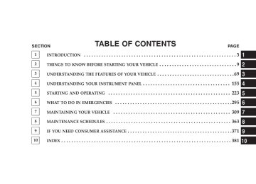
m Instrument Panel Features . . . . . . . . . . . . . . . . . 158
m Instrument Cluster—Premium . . . . . . . . . . . . . . 159
m Instrument Cluster Descriptions . . . . . . . . . . . . 160
m Electronic Vehicle Information Center (EVIC) –If Equipped . . . . . . . . . . . . . . . . . . . . . . . . . . . 171
N Engine Oil Change Indicator System . . . . . . . . 172
N EVIC Functions . . . . . . . . . . . . . . . . . . . . . . . 173
N Compass/Temperature/Audio . . . . . . . . . . . . 174
N Average Fuel Economy . . . . . . . . . . . . . . . . . 174N Distance To Empty (DTE) . . . . . . . . . . . . . . . 175
N Elapsed Time . . . . . . . . . . . . . . . . . . . . . . . . 175
N Tire Pressure Monitor (TPM) . . . . . . . . . . . . . 175
N Personal Settings (Customer ProgrammableFeatures)
. . . . . . . . . . . . . . . . . . . . . . . . . . . 175
m Radio General Information . . . . . . . . . . . . . . . . 181
N Radio Broadcast Signals . . . . . . . . . . . . . . . . . 181
N Two Types Of Signals . . . . . . . . . . . . . . . . . . 181
N Electrical Disturbances . . . . . . . . . . . . . . . . . . 181156 UNDERSTANDING YOUR INSTRUMENT PANEL
N AM Reception . . . . . . . . . . . . . . . . . . . . . . . 181
N FM Reception . . . . . . . . . . . . . . . . . . . . . . . . 181
m Electronic Digital Clock . . . . . . . . . . . . . . . . . . 182
N Clock Setting Procedure . . . . . . . . . . . . . . . . . 182m Sales Code REF — AM/FM/CD (Single Disc)
Radio With Optional Satellite Radio And Hands Free Phone Capability . . . . . . . . . . . . . . . . . . . 183
N Operating Instructions - Radio Mode . . . . . . . 183
N Operation Instructions - CD Mode . . . . . . . . . 187
N Operation Instructions - Auxiliary Mode . . . . . 189
N Operating Instructions - Hands Free Phone —If Equipped . . . . . . . . . . . . . . . . . . . . . . . . . 190
m Sales Code RAQ – AM/FM/CD (6-Disc) Radio
With Optional Satellite Radio, Hands Free Phone, And Vehicle Entertainment Systems (VES) Capabilities . . . . . . . . . . . . . . . . . . . . . . . . . . . 190
N Operating Instructions - Radio Mode . . . . . . . 191
N Operation Instructions - (CD Mode For CDAudio Play)
. . . . . . . . . . . . . . . . . . . . . . . . . 196
N Load/Eject Button (CD Mode For CD Audio
Play)
. . . . . . . . . . . . . . . . . . . . . . . . . . . . . . 197
. . . . . . . . . . . . . 199N Notes On Playing MP3 Files N Operation Instructions - (CD Mode For MP3
Audio Play)
. . . . . . . . . . . . . . . . . . . . . . . . . 202
N Load/Eject Button (CD Mode For MP3 Play) . . 202N Operating Instructions - Satellite Radio —
If Equipped . . . . . . . . . . . . . . . . . . . . . . . . . 190
m Sales Code REC — AM/FM/CD (6–Disc) Radio
With Navigation System . . . . . . . . . . . . . . . . . . 204
N Operating Instructions — Satellite Radio
(If Equipped)
. . . . . . . . . . . . . . . . . . . . . . . . 205
N REC Setting The Clock . . . . . . . . . . . . . . . . . 205
N Audio Clock Display . . . . . . . . . . . . . . . . . . . 207
m Satellite Radio — If Equipped . . . . . . . . . . . . . . 208
N System Activation . . . . . . . . . . . . . . . . . . . . . 208
N Electronic Serial Number/Sirius IdentificationNumber (ESN/SID) . . . . . . . . . . . . . . . . . . . . 209
N Selecting Satellite Mode In REF, And RAQ,
Radios . . . . . . . . . . . . . . . . . . . . . . . . . . . . . 209
N Selecting a Channel . . . . . . . . . . . . . . . . . . . . 210
N Storing And Selecting Pre-Set Channels . . . . . . 210
N Using The PTY (Program Type) Button(If Equipped)
. . . . . . . . . . . . . . . . . . . . . . . . 211
N PTY Button 9Scan9 . . . . . . . . . . . . . . . . . . . . . 211UNDERSTANDING YOUR INSTRUMENT PANEL 157
N PTY Button 9Seek9 . . . . . . . . . . . . . . . . . . . . . 211
N Satellite Antenna . . . . . . . . . . . . . . . . . . . . . . 211
N Reception Quality . . . . . . . . . . . . . . . . . . . . . 212
m Remote Sound System Controls — If Equipped . . 212
N Radio Operation . . . . . . . . . . . . . . . . . . . . . . 213
N CD Player . . . . . . . . . . . . . . . . . . . . . . . . . . 213
m CD/DVD Disc Maintenance . . . . . . . . . . . . . . . 214
m Radio Operation And Cellular Phones . . . . . . . . 214
m Climate Controls . . . . . . . . . . . . . . . . . . . . . . . 214
N Climate Controls . . . . . . . . . . . . . . . . . . . . . . 214
N Air Conditioning . . . . . . . . . . . . . . . . . . . . . 218
N Air Filtration System – If Equipped . . . . . . . . 219
N Operating Tips . . . . . . . . . . . . . . . . . . . . . . . 220158 UNDERSTANDING YOUR INSTRUMENT PANEL
INSTRUMENT PANEL FEATURES
1 — Air Outlet 2 —Demisters 3 — Instrument Cluster 4 — Radio
5 — Glove Box 6 — Storage Bin 7 — Climate Controls 8 — Heated Seat Switches — If Equipped
9 — Hazard Warning Flasher 10 — ESP OFF Switch — If Equipped
INSTRUMENT CLUSTER—PREMIUM
UNDERSTANDING YOUR INSTRUMENT PANEL 159
160 UNDERSTANDING YOUR INSTRUMENT PANEL
INSTRUMENT CLUSTER DESCRIPTIONS
1. Fuel Gauge/Fuel Door Location
When the ignition switch is in the ON position, the pointer will show the level of fuel remain- ing in the fuel tank. The fuel pump symbol points to the side of the vehicle where the fuel door is located. 2. Voltage Warning Light
This light shows the status of the electrical charg- ing system. The light should come on when the ignition switch is first turned ON and remain on briefly as a bulb check. If the Charging System light remains on, or comes on while driving, it means that the vehicle is experiencing a problem with the charging system. Obtain SERVICE IMMEDIATELY. See your authorized dealer.
3. Electronic Throttle Control (ETC) Warning Light
This light informs you of a problem with the Electronic Throttle Control system. If a prob- lem is detected, the light will come on while the engine is running. If the light remains lit with the engine running your vehicle will usually be drivable and not need towing, however see your dealer for service as soon as possible. If the light is flashing when the engine is running you may experience power loss, an elevated/rough idle, and increased brake pedal effort, and your vehicle may require towing. Immediate service is required. The light will come on when the ignition switch is first turned on and remain on briefly as a bulb check. This is normal. If the light does not come on during starting, have the system checked by an authorized dealer.
4. Oil Pressure Warning Light
Shows low engine oil pressure. The light will come on and remain on when the ignition switch is turned from the OFF to the ON position, and the light will turn off after the engine is started. If the bulb does not come on during starting, have the system checked by an authorized dealer. If the light comes on and remains on while driving, stop the vehicle and shut off the engine. DO NOT OPERATE THE VEHICLE UNTIL THE CAUSE IS CORRECTED. The light does not show the quantity of oil in the engine. This can be determined using the procedure shown in Section 7. 5. Low Fuel Warning Light
When the fuel level drops to 2 gallons, the fuel symbol will light and a single chime will sound.
UNDERSTANDING YOUR INSTRUMENT PANEL 161
6. Speedometer Indicates vehicle speed. 7. Airbag Warning Light
The light comes on and remains on for 6 to 8
seconds as a bulb check when the ignition switch is first turned ON. If the light does not come on during starting, stays on, or comes on while driving, have the system checked by an authorized dealer. 8. Turn Signal Indicator LightThe arrows will flash in unison with the exterior turn signal, when using the turn signal lever.
9. High Beam Indicator Light
This light shows that the headlights are on high beam. Push the turn signal lever away from the steering wheel to switch the headlights from high or low beam.
162 UNDERSTANDING YOUR INSTRUMENT PANEL
10. Anti-Lock Brake Warning Light — If Equipped
This light monitors the Anti-Lock Brake System (ABS) described elsewhere in this manual. This light will come on when the ignition key is turned to the ON position and may stay on for as long as four seconds.
If the ABS light remains on or comes on during driving, it indicates that the Anti-Lock portion of the brake system is not functioning and that service is required, however, the conventional brake system will continue to operate normally provided that the BRAKE warning light is not on. If the ABS light is on, the brake system should be serviced as soon as possible to restore the benefit of Anti-Lock Brakes.
The warning light should be checked frequently to assure that it is operating properly. Turn the ignition key to the on position, but do not start the vehicle. The light should come on. If the light does not come on, have the system checked by an authorized dealer. 11. Seat Belt Reminder Light
When the ignition switch is first turned ON, this light will come on for about six seconds. A chime will sound if you have not pulled the shoulder belt out of the retractor. This is a reminder to “buckle up”. If you do not buckle up, the light will remain on. 12. Tachometer The white area of the scale shows the permissible engine revolutions-per-minute (rpm x 1000) for each gear range. Before reaching the red area, ease up on the accelerator to prevent engine damage.
13. Engine Coolant Temperature Warning Light
This light warns of an overheated engine condi- tion. If the engine is critically hot, a warning chime will sound 10 times. After the chime turns off, the engine will still be critically hot until the light goes out. 14. Brake System Warning Light
This light monitors various brake functions, in- cluding brake fluid level and parking brake appli- cation. If the brake light turns on, it may indicate that the parking brake is applied, there is a low brake fluid level or there is a problem with the anti-lock brake system. The dual brake system provides a reserve braking capac- ity in the event of a failure to a portion of the hydraulic system. Failure of either half of the dual brake system is indicated by the Brake Warning Light which will turn on when the brake fluid level in the master cylinder has dropped below a specified level. The light will remain on until the cause is corrected.
UNDERSTANDING YOUR INSTRUMENT PANEL 163
NOTE: The light may flash momentarily during sharp cornering maneuvers which change fluid level condi- tions. The vehicle should have service performed, and the brake fluid level checked. If brake failure is indicated, immediate repair is neces- sary.
WARNING!
Driving a vehicle with the brake light on is danger- ous. Part of the brake system may have failed. It will take longer to stop the vehicle. You could have an accident. Have the vehicle checked immediately.
Vehicles equipped with Anti-Lock brakes (ABS), are also equipped with Electronic Brake Force Distribution (EBD).
164 UNDERSTANDING YOUR INSTRUMENT PANEL
In the event of an EBD failure, the Brake Warning Light will turn on along with the ABS Light. Immediate repair to the ABS system is required. The operation of the Brake Warning Light can be checked by turning the ignition switch from the OFF position to the ON position. The light should illuminate for approxi- mately two seconds. The light should then turn off unless the parking brake is applied or a brake fault is detected. If the light does not illuminate, have the light inspected by an authorized dealer. The light also will turn on when the parking brake is applied with the ignition switch in the ON position. NOTE: This light shows only that the parking brake is applied. It does not show the degree of brake application.
15. Transmission Temperature Warning Light
During sustained high speed driving on hot days, the automatic transaxle oil may become too hot. If this happens, the transmission over- indicator light will come on and the heat vehicle will slow slightly until the automatic transaxle cools down enough to allow a return to the requested speed. If the high speed is maintained, the overheating will reoccur as before in a cyclic fashion. 16. Security Alarm System Indicator Light — If Equipped This light will flash rapidly for several seconds when the alarm system is arming. The light will begin to flash slowly indicating that the system is armed. 17. Temperature Gauge If the pointer rises to the H (red) mark, the instrument cluster will sound a chime. Pull over and stop the vehicle. Idle the vehicle with the air conditioner turned off until
the pointer drops back into the normal range. If the pointer remains on the H (red) mark, turn the engine off immediately and call for service. There are steps that you can take to slow down an impending overheat condition. If your air conditioning is on, turn it off. The air conditioning system adds heat to the engine cooling system and turning off the A/C removes this heat. You can also turn the Temperature control to maximum heat, the Mode control to Floor and the Fan control to High. This allows the heater core to act as a supplement to the radiator and aids in removing heat from the engine cooling system. 18. Cruise Indicator Light — If Equipped
This indicator shows that the Speed Control System is ON.
19. Cruise SET Indicator Light — If Equipped This indicator shows that the Speed Control System is SET.
UNDERSTANDING YOUR INSTRUMENT PANEL 165
20. Transmission Range Indicator This display indicator shows the automatic transmission gear selection. 21. Odometer/Trip Odometer Reset Button Press this button to change the display from odometer to either of the two trip odometer settings. Trip A or Trip B will appear when in the trip odometer mode. Push in and hold the button for two seconds to reset the trip odometer to 0 miles or kilometers. The odometer must be in trip mode to reset. 22. Tire Pressure Monitoring Telltale Light — If Equipped
Each tire, including the spare (if provided), should be checked monthly when cold and inflated to the inflation pressure recommended by the vehicle manufacturer on the vehicle placard or tire inflation pressure label. (If your vehicle has tires of a different size than the size indicated on the
166 UNDERSTANDING YOUR INSTRUMENT PANEL
vehicle placard or tire inflation pressure label, you should determine the proper tire inflation pressure for those tires.) As an added safety feature, your vehicle has been equipped with a tire pressure monitoring system (TPMS) that illuminates a low tire pressure telltale when one or more of your tires are significantly under-inflated. Ac- cordingly, when the low tire pressure telltale illuminates, you should stop and check your tires as soon as possible, and inflate them to the proper pressure. Driving on a significantly under-inflated tire causes the tire to over- heat and can lead to tire failure. Under-inflation also reduces fuel efficiency and tire tread life, and may affect the vehicle’s handling and stopping ability. Please note that the TPMS is not a substitute for proper tire maintenance, and it is the driver’s responsibility to maintain correct tire pressure, even if under-inflation has not reached the level to trigger illumination of the TPMS low tire pressure telltale.
Your vehicle has also been equipped with a TPMS malfunction indicator to indicate when the system is not operating properly. The TPMS malfunction indicator is combined with the low tire pressure telltale. When the system detects a malfunction, the telltale will flash for approximately one minute and then remain continuously illuminated. This sequence will continue upon subse- quent vehicle start-ups as long as the malfunction exists. When the malfunction indicator is illuminated, the sys- tem may not be able to detect or signal low tire pressure as intended. TPMS malfunctions may occur for a variety of reasons, including the installation of replacement or alternate tires or wheels on the vehicle that prevent the TPMS from functioning properly. Always check the TPMS malfunction telltale after replacing one or more tires or wheels on your vehicle to ensure that the replace- ment or alternate tires and wheels allow the TPMS to continue to function properly.
If this indicator comes on, it will brighten to NOTE: FULL DAYTIME INTENSITY and will not be dimmable.
CAUTION!
The TPMS has been optimized for the original equipment tires and wheels. TPMS pressures and warning have been established for the tire size equipped on your vehicle. Undesirable system opera- tion or sensor damage may result when using re- placement equipment that is not of the same size, type, and/or style. Aftermarket wheels can cause sensor damage. Do not use tire sealant from a can, or balance beads if your vehicle is equipped with a TPMS, as damage to the sensors may result.
23. 4WD Indicator Light — If Equipped This light indicates the vehicle is in 4WD.
UNDERSTANDING YOUR INSTRUMENT PANEL 167
24. Odometer/Trip Odometer A vacuum fluorescent display indicates the total distance the vehicle has been driven. Also, the cluster will display, replacing the odometer/trip odometer, vehicle warning messages such as: door/gate ajar and loose gas cap. Loose gas cap will be displayed from the Odometer/Trip Odometer on all models. If vehicle is equipped with the optional Elec- NOTE: tronic Vehicle Information Center (EVIC) in the instru- ment cluster, all warnings including “door”, and “gATE” will only be displayed in the EVIC display. For additional information, refer to “Electronic Vehicle Information Cen- ter — If Equipped” in Section 3. U.S. federal regulations require that upon transfer of vehicle ownership, the seller certify to the purchaser the correct mileage that the vehicle has been driven. There- fore, if the odometer reading is changed during repair or
168 UNDERSTANDING YOUR INSTRUMENT PANEL
replacement, be sure to keep a record of the reading before and after the service so that the correct mileage can be determined. Change Oil Message Your vehicle is equipped with an engine oil change indicator system. The “Change Oil” message will flash in the instrument cluster odometer for approximately 12
seconds after a single chime has sounded to indicate the next scheduled oil change interval. The engine oil change indicator system is duty cycle based, which means the engine oil change interval may fluctuate dependent upon your personal driving style. Unless reset, this message will continue to display each time you turn the ignition switch to the ON/RUN position. To turn off the message temporarily, press and release the Trip Odometer button on the instrument cluster. To reset the oil change indica- tor system (after performing the scheduled maintenance) refer to the following procedure.1. Turn the ignition switch to the ON position (Do not start the engine). 2. Fully depress the accelerator pedal slowly three times within 10 seconds. 3. Turn the ignition switch to the OFF/LOCK position. If the indicator message illuminates when you NOTE: start the vehicle, the oil change indicator system did not reset. If necessary repeat this procedure. 25. Malfunction Indicator Light
This light is part of an onboard diagnostic system called OBD that monitors emissions, engine, and automatic transmission control systems. The light will illuminate when the key is in the ON/RUN position before engine start. If the bulb does not come on when turning the key from OFF to ON/RUN, have the condi- tion checked promptly.
Certain conditions such as a loose or missing gas cap, poor fuel quality, etc. may illuminate the light after engine start. The vehicle should be serviced if the light stays on through several of your typical driving cycles. In most situations the vehicle will drive normally and will not require towing. If the Malfunction Indicator Light flashes when the engine is running, serious conditions may exist that could lead to immediate loss of power or severe catalytic converter damage. The vehicle should be serviced as soon as possible if this occurs. If this indicator comes on, it will brighten to NOTE: FULL DAYTIME INTENSITY and will not be dimmable. 26. Front Fog Light Indicator Light — If Equipped
This light shows when the front fog lights are ON.
UNDERSTANDING YOUR INSTRUMENT PANEL 169
27. Electronic Stability Program (ESP) Indicator Light/Traction Control System (TCS) Indicator Light — If Equipped
If this indicator light flashes during accelera- tion, apply as little throttle as possible. While driving, ease up on the accelerator. Adapt your speed and driving to the prevailing road con- ditions, and do not switch off the ESP, or TCS — if equipped. 28. Electronic Stability Program (ESP) Indicator Light The malfunction lamp for the ESP is combined with BAS. The yellow “ESP/BAS Warning Lamp” comes on when the ignition switch is turned to the “ON” position. They should go out with the engine running. If the “ESP/BAS Warning Lamp” comes on continuously with the engine running, a malfunction has been detected in either the ESP or the BAS system. If this light remains on after several ignition
170 UNDERSTANDING YOUR INSTRUMENT PANEL
cycles, and the vehicle has been driven several miles at speeds greater than 30 mph (48 km/h), see your autho- rized dealer as soon as possible. 29. 4WD! Warning Light — If Equipped
This light monitors the Four -Wheel-Drive (4WD) system. The light will come on, for a bulb check, when the ignition key is turned to the ON position and may stay on for as long as 3 seconds.
When lit solid: There is an 4WD system fault. 4WD performance will be at a reduced level. Service the 4WD system soon. When blinking: The 4WD system is temporarily dis- abled due to overload condition.
30. Electronic Vehicle Information Center Display—If Equipped When the appropriate conditions exist, this display shows the Electronic Vehicle Information Center (EVIC) messages. 31. Electronic Vehicle Information Center (EVIC) Button—If Equipped Pushing this button, will change the display to the choices available for EVIC.
ELECTRONIC VEHICLE INFORMATION CENTER (EVIC) – IF EQUIPPED
EVIC Location
The Electronic Vehicle Information Center (EVIC) fea- tures a driver-interactive display. It is located in the lower left part of the cluster below the fuel and engine tem- perature gauge. The EVIC consists of the following:
UNDERSTANDING YOUR INSTRUMENT PANEL 171
† System Status † Vehicle information warning message displays † Personal Settings (customer programmable features) † Compass heading † Outside temperature display † Trip computer functions † UConnect™ hands-free communication system dis- plays — If Equipped † Audio mode display † Tire Pressure Monitor (TPM) When the appropriate conditions exist, the Electronic Vehicle Information Center (EVIC) displays the following messages. † Turn Signal On (with a continuous warning chime)
172 UNDERSTANDING YOUR INSTRUMENT PANEL
chime)
chime)
† Left Front Turn Signal Lamp Out (with a single chime) † Left Rear Turn Signal Lamp Out (with a single chime) † Right Front Turn Signal Lamp Out (with a single † Right Rear Turn Signal Lamp Out (with a single † RKE Battery Low (with a single chime) † Personal Settings Not Available – Vehicle Not in Park (automatic transmissions) or vehicle is in motion (manual transmissions). † Left/Right Front Door Ajar (one or more, with a single † Left/Right Rear Door Ajar (one or more, with a single
chime if speed is above 1 mph)
chime if speed is above 1 mph)
motion)
† Door (S) Ajar (with a single chime if vehicle is in † Gate Ajar (with a single chime) † Headlamps On † Key In Ignition † Check TPM System Engine Oil Change Indicator System
Oil Change Required Your vehicle is equipped with an engine oil change indicator system. The “Oil Change Required” message will flash in the EVIC display for approximately 10
seconds after a single chime has sounded to indicate the next scheduled oil change interval. The engine oil change indicator system is duty cycle based, which means the engine oil change interval may fluctuate dependent upon your personal driving style.Unless reset, this message will continue to display each time you turn the ignition switch to the ON/RUN position. To turn off the message temporarily, press and release the Trip Odometer button on the instrument cluster. To reset the oil change indicator system (after performing the scheduled maintenance) refer to the fol- lowing procedure. 1. Turn the ignition switch to the ON position (Do not start the engine). 2. Fully depress the accelerator pedal slowly three times within 10 seconds. 3. Turn the ignition switch to the OFF/LOCK position. If the indicator message illuminates when you NOTE: start the vehicle, the oil change indicator system did not reset. If necessary repeat this procedure.
UNDERSTANDING YOUR INSTRUMENT PANEL 173
EVIC Functions
EVIC Button
Press the EVIC button until one of the following func- tions are displayed on the EVIC: † Compass/Temperature/Audio † Average Fuel Economy
174 UNDERSTANDING YOUR INSTRUMENT PANEL
† Distance To Empty (DTE) † Elapsed Time † Tire Pressure Monitor (TPM) † Personal Settings To Reset The Display Pressing and holding the EVIC button once will clear the function currently being displayed. Reset will only occur if a resettable function is currently being displayed. To reset all resettable functions, press and release the EVIC button a second time within 3 seconds of resetting the currently displayed function (Reset ALL will be dis- played during this 3 second window).
Compass/Temperature/Audio
Press and release the EVIC button to display one of eight compass headings to indicate the direction the vehicle is facing, the outside temperature and the current radio station. For additional information regarding the compass, refer to Personal Settings (Customer Programmable Features) in this section. Average Fuel Economy Shows the average fuel economy since the last reset. When the fuel economy is reset, the display will read “RESET” or show dashes for two seconds. Then, the history information will be erased, and the averaging will continue from the last fuel reading before the reset.
Distance To Empty (DTE) Shows the estimated distance that can be travelled with the fuel remaining in the tank. This estimated distance is determined by a weighted average of the instantaneous and average fuel economy, according to the current fuel tank level. This is not resettable. NOTE: Significant changes in driving style or vehicle loading will greatly affect the actual drivable distance of the vehicle, regardless of the DTE displayed value. When the DTE value is less than 30 miles estimated driving distance, the DTE display will change to a text display of 9LOW FUEL9. This display will continue until the vehicle runs out of fuel. Adding a significant amount of fuel to the vehicle will turn off the 9LOW FUEL9 text and a new DTE value will be displayed, based on the current values in the DTE calculation and the current fuel tank level.
UNDERSTANDING YOUR INSTRUMENT PANEL 175
Elapsed Time Shows the total elapsed time of travel since the last reset when the ignition switch is in the ACC position. Elapsed time will increment when the ignition switch is in the ON or START position. Tire Pressure Monitor (TPM) Refer to Section 5, “Tire Pressure Monitoring System (TPMS) for system operation. Personal Settings (Customer Programmable Features) This allows the driver to set and recall features when the transmission is in PARK (automatic transmission) or the vehicle is stopped (manual transmissions). Press and release the EVIC button until Personal Settings is displayed in the EVIC. Use the EVIC button to display one of the following choices:
176 UNDERSTANDING YOUR INSTRUMENT PANEL
Language When in this display you may select different languages for all display nomenclature, including the trip functions. Pressing the EVIC button while in this display selects English, Espanol, Deutsch, Italiano, or Francais depend- ing on availability. As you continue the displayed infor- mation will be shown in the selected language. NOTE: UConnect™ language will not change using the EVIC. Please refer to “Language Selection” in the HANDS–FREE COMMUNICATION (UConnect™) — IF EQUIPPED section of this manual for details. Lock Doors Automatically at 15 mph (24 km/h) When ON is selected all doors lock automatically when the speed of the vehicle reaches 15 mph (24 km/h). Press and hold the EVIC button when in this display until “ON” or “OFF” appears to make your selection.
Auto Unlock On Exit When ON is selected all the vehicle’s doors will unlock when the driver’s door is opened if the vehicle is stopped (manual transmissions) or the vehicle is stopped and the transmission is in P (Park) or N (Neutral) position (automatic transmissions). Press and hold the EVIC but- ton when in this display until “ON” or “OFF” appears to make your selection. Remote Unlock Driver’s Door 1st When DRIVER’S DOOR 1ST is selected only the driv- er’s door will unlock on the first press of the remote keyless entry unlock button and require a second press to unlock the remaining locked doors. When REMOTE UNLOCK ALL DOORS is selected all of the doors will unlock at the first press of the remote keyless entry unlock button. Press and hold the EVIC button when in this display until “DRIVER’S DOOR 1ST” or “ALL DOORS” appears to make your selection.
Sound Horn with Remote Key Lock When ON is selected a short horn sound will occur when the remote keyless entry “Lock” button is pressed. This feature may be selected with or without the flash lights on lock/unlock feature. Press and hold the EVIC button when in this display until “ON” or “OFF” appears to make your selection. Flash Lights with Remote Key Lock When ON is selected, the front and rear turn signals will flash when the doors are locked or unlocked using the remote keyless entry transmitter. This feature may be selected with or without the sound horn on lock feature selected. Press and hold the EVIC button when in this display until “ON” or “OFF” appears to make your selection. Delay Turning Headlamps Off When this feature is selected the driver can choose to have the headlamps remain on for 0, 30, 60, or 90 seconds
UNDERSTANDING YOUR INSTRUMENT PANEL 177
when exiting the vehicle. Press and hold the EVIC button when in this display until 0, 30, 60, or 90 appears to make your selection. Headlamps On With Wipers (Available with Auto Headlights Only) When ON is selected and the headlight switch is in the AUTO position, the headlights will turn on approxi- mately 10 seconds after the wipers are turned on. The headlights will also turn off when the wipers are turned off if they were turned on by this feature. Press and hold the EVIC button when in this display until “ON” or “OFF” appears to make your selection. NOTE: Turning the headlights on during the daytime causes the instrument panel lights to dim. To increase the brightness, refer to “Lights” in this section. Delay Power Off to Accessories Until Exit When this feature is selected, the power window switches, radio, hands–free system, power sunroof, and
178 UNDERSTANDING YOUR INSTRUMENT PANEL
power outlets will remain active for up to 60 minutes after the ignition switch has been turned off. Opening a vehicle door will cancel this feature. Press and hold the EVIC button when in this display until “Off”, “45 sec.”, “5 min.”, or “10 min.” appears to make your selection. Turn Headlamps on with Remote Key Unlock When this feature is selected the headlamps will activate and remain on for up to 90 seconds when the doors are unlocked using the remote keyless entry transmitter. Press and hold the EVIC button when in this display until “OFF”, “30 sec.”, “60 sec.”, or “90 sec.” appears to make your selection. Confirmation of Voice Commands — If Equipped When ON is selected all voice commands from the U-Connect system are confirmed. Press and hold the EVIC button when in this display until “ON” or “OFF” appears to make your selection.
Display English or Metric The EVIC, odometer, and navigation system units can be changed between English and Metric. Press and hold the EVIC button when in this display until “US” or “METRIC” appears to make your selection. Compass Variance Compass Variance is the difference between magnetic North and Geographic North. In some areas of the country, the difference between magnetic and geographic North is great enough to cause the compass to give false readings. In order to ensure compass accuracy, the com- pass variance should be set to the zone number on the compass variance map that corresponds to the current location of the vehicle. NOTE: Magnetic materials should be kept away from the Instrument Panel. This is where the compass sensor is located.
UNDERSTANDING YOUR INSTRUMENT PANEL 179
To Set the Variance: with the ignition in the ON position, with a short button press (less than one second) press and release the EVIC button several times until you have displayed the Personal Settings (Customer Program- mable Features) menu. Once in the Personal Settings (Customer Programmable Features) menu, press and release (less than one second) the EVIC button several times until “Compass Variance” is highlighted. The “Compass Variance” message and the current variance zone number will be displayed. To change the zone, press and hold (longer than two seconds) the EVIC button to increment the variance one step. Repeat as necessary, with individual long (for at least 1 second) EVIC button presses for each increment, until the desired variance is achieved. To exit the Variance Programming, press the EVIC button with a short (less than one second) button press.
180 UNDERSTANDING YOUR INSTRUMENT PANEL
NOTE: The factory default Zone is 8. During program- ming, the Zone value will wrap around from Zone 15 to Zone 1. Compass Calibration The Compass will automatically calibrate if the Cal indicator is flashing, by driving around slowly (under 5
mph / 8 km/h) in one or more complete circles in an area free from large metallic objects or power lines, until the Cal indicator turns off. If during normal use the compass appears erratic, inaccurate or abnormal, you may wish to manually calibrate the compass. Prior to calibrating the compass make sure the proper zone is selected. To Manually Calibrate the Compass: start the engine and leave the transmission in the PARK position. Using a short button press (less than one second), press and release the EVIC button several times until the EVIC displays the Personal Settings (Customer Programmable Features) menu. Once in the Personal Settings (CustomerProgrammable Features) menu, press and release (less than one second) the EVIC button several times until “Calibrate Compass (Yes)” is displayed. Using a long button press (more than one second), pressing the EVIC button will place the Compass in calibration mode. The Cal indicator will come on continuously in the EVIC display to indicate that the compass is now in the calibration mode and that the vehicle can now be driven to calibrate. (A short EVIC button press from the 9Cali- brate Compass (Yes)9 screen will exit the EVIC Customer Programmable features, and return it to its normal oper- ating mode). To complete the compass calibration, drive the vehicle in one or more complete 360 degree circles under 5 mph (8 km/h) in an area free from power lines, large metallic objects, until the CAL indicator turns off. The compass will now function normally.
RADIO GENERAL INFORMATION
Radio Broadcast Signals Your new radio will provide excellent reception under most operating conditions. Like any system, however, car radios have performance limitations, due to mobile op- eration and natural phenomena, which might lead you to believe your sound system is malfunctioning. To help you understand and save you concern about these “ap- parent” malfunctions, you must understand a point or two about the transmission and reception of radio sig- nals. Two Types of Signals There are two basic types of radio signals... AM or Amplitude Modulation, in which the transmitted sound causes the amplitude, or height, of the radio waves to vary... and FM or Frequency Modulation, in which the frequency of the wave is varied to carry the sound.
UNDERSTANDING YOUR INSTRUMENT PANEL 181
Electrical Disturbances Radio waves may pick up electrical disturbances during transmission. They mainly affect the wave amplitude, and thus remain a part of the AM reception. They interfere very little with the frequency variations that carry the FM signal. AM Reception AM sound is based on wave amplitude, so AM reception can be disrupted by such things as lightning, power lines and neon signs. FM Reception Because FM transmission is based on frequency varia- tions, interference that consists of amplitude variations can be filtered out, leaving the reception relatively clear, which is the major feature of FM radio. NOTE: The radio, steering wheel radio controls (if equipped), and 6 disc CD/DVD changer (if equipped)
182 UNDERSTANDING YOUR INSTRUMENT PANEL
will remain active for up to 10 minutes after the ignition switch has been turned off. Opening a vehicle front door will cancel this feature.
ELECTRONIC DIGITAL CLOCK The clock and radio each use the display panel built into the radio. A digital readout shows the frequency and/or time in hours and minutes (depending on your radio model) whenever the ignition switch is in the “ON” or “ACC” position. When the ignition switch is in the “OFF” position, or when the radio frequency is being displayed, time keep- ing is accurately maintained. On the AM/FM/CD (6-disc) radio the time button alter- nates the location of the time and frequency on the display. On the AM/FM/CD (single-disc) radio only one of the two, time or frequency is displayed.
Clock Setting Procedure
1. Press and hold the time button until the hours blink. 2. Adjust the hours by turning the right side Tune / Audio control. 3. After the hours are adjusted, press the right side Tune / Audio control to set the minutes. 4. Adjust the minutes using the right side Tune / Audio control. 5. To exit, press any button/knob or wait approximately 5 seconds.
SALES CODE REF — AM/FM/CD (SINGLE DISC) RADIO WITH OPTIONAL SATELLITE RADIO AND HANDS FREE PHONE CAPABILITY
NOTE: The radio sales code is located on the lower right side of your radio faceplate.
REF Radio
UNDERSTANDING YOUR INSTRUMENT PANEL 183
Operating Instructions - Radio Mode
NOTE: The ignition switch must be in the ON or ACC position to operate the radio. Power Switch/Volume Control (Rotary) Press the ON/VOL control to turn the radio ON. Press the ON/VOL a second time to turn OFF the radio. Electronic Volume Control The electronic volume control turns continuously (360
degrees) in either direction without stopping. Turning the volume control to the right increases the volume and to the left decreases it. When the audio system is turned on, the sound will be set at the same volume level as last played. For your convenience, the volume can be turned down, but not up, when the audio system is off and the ignition is ON.184 UNDERSTANDING YOUR INSTRUMENT PANEL
Mode Button (Radio Mode) Press the mode button repeatedly to select between the CD player and Satellite Radio (if equipped). SEEK Button (Radio Mode) Press and release the SEEK button to search for the next listenable station in either AM/FM or Satellite (if equipped) mode. Press the right side of the button to seek up and the left side to seek down. The radio will remain tuned to the new station until you make another selec- tion. Holding the button will bypass stations without stopping until you release it. MUTE Button (Radio Mode) Press the MUTE button to cancel the sound from the speakers. 9MUTE9 will display. Press the MUTE button a second time and the sound from the speakers will return. Rotating the volume control, turning the radio ON/OFF, or turning ON/OFF the ignition, will cancel the MUTE feature.
In Hands Free Phone (if equipped) mode, the
NOTE: MUTE button mutes the microphone. SCAN Button (Radio Mode) Pressing the SCAN button causes the tuner to search for the next listenable station in either, AM, FM, or Satellite (if equipped) frequencies, pausing for 5 seconds at each listenable station before continuing to the next. To stop the search, press SCAN a second time. PSCAN Button (Radio Mode) Pressing the PSCAN button causes the tuner to scan through preset stations in either, AM, FM, or Satellite (if equipped) frequencies, pausing for 5 seconds at each preset station before continuing to the next. To stop the search, press PSCAN a second time. Time Button Press the time button and the time of day will display for 5 seconds.
Clock Setting Procedure 1. Press and hold the time button until the hours blink. 2. Adjust the hours by turning the right side Tune/ Audio control. 3. After the hours are adjusted, press the right side Tune/Audio control to set the minutes. The minutes will begin to blink. 4. Adjust the minutes using the right side Tune/Audio control. 5. To exit, press any button/knob or wait 5 seconds. RW/FF (Radio Mode) Pressing the rewind/fast forward button causes the tuner to search for the next frequency in the direction of the arrows. This feature operates in either AM, FM or Satel- lite (if equipped) frequencies.
UNDERSTANDING YOUR INSTRUMENT PANEL 185
TUNE Control (Radio Mode) Turn the right side rotary control clockwise to increase or counter-clockwise to decrease the frequency. AM/FM Button (Radio Mode) Press the button to select AM or FM Modes. Setting the Tone, Balance, and Fade Press the rotary TUNE control and BASS will display. Turn the TUNE control to the right or left to increase or decrease the Bass tones. Press the rotary TUNE control a second time and MID will display. Turn the TUNE control to the right or left to increase or decrease the Mid Range tones. Press the rotary TUNE control a third time and TREB will display. Turn the TUNE control to the right or left to increase or decrease the Treble tones.
186 UNDERSTANDING YOUR INSTRUMENT PANEL
Press the rotary TUNE control a fourth time and BAL will display. Turn the TUNE control to the right or left to adjust the sound level from the right or left side speakers. Press the rotary TUNE control a fifth time and FADE will display. Turn the TUNE control to the left or right to adjust the sound level between the front and rear speak- ers. Press the tune control again or wait 5 seconds to exit setting tone, balance, and fade. RND/SET Button (Radio Mode) To SET The Push-Button Memory When you are receiving a station that you wish to commit to push-button memory, press the SET button. The symbol SET 1 will now show in the display window. Select the button (1-6) you wish to lock onto this station and press and release that button. If a button is not
selected within 5 seconds after pressing the SET button, the station will continue to play but will not be stored into push-button memory. You may add a second station to each push-button by repeating the above procedure with this exception: Press the SET button twice and SET 2 will show in the display window. Each button can be set for SET 1 and SET 2 in both AM and FM. This allows a total of 12 AM, 12 FM, and 12 Satellite (if equipped) stations to be stored into push-button memory. The stations stored in SET 2
memory can be selected by pressing the push-button twice. Every time a preset button is used, a corresponding button number will display. Preset Buttons 1 - 6 (Radio Mode) These buttons tune the Radio to the stations that you commit to push-button memory {12 AM, 12 FM, and 12
Satellite (if equipped) stations}.Operation Instructions - CD Mode
NOTE: The ignition switch must be in the ON or ACC position to operate the radio. Inserting The Compact Disc (Single CD Player) Gently insert one CD into the CD player with the CD label facing up. The CD will automatically be pulled into the CD Player and the CD icon will illuminate on the radio display. If the volume control is ON, the unit will switch to CD mode and begin to play. The display will show the track number and play time in minutes and seconds. Play will begin at the start of track one. NOTE: † On some vehicles, you may insert or eject a disc with
the radio or ignition switch OFF.
UNDERSTANDING YOUR INSTRUMENT PANEL 187
† If you insert a disc with the ignition ON and the radio OFF, the CD will automatically be pulled into the CD Player.
† This radio does not play discs with MP3 tracks. SEEK Button (CD Mode) Press the right side of the SEEK button for the next track on the CD. Press the left side of the button to return to the beginning of the current track, or return to the beginning of the previous track if the CD is within the first 10
seconds of the current selection. MUTE Button (CD Mode) Press the MUTE button to cancel the sound from the speakers. 9MUTE9 will display. Press the MUTE button a second time and the sound from the speakers will return. Rotating the volume control or turning OFF the ignition will also return the sound from the speakers.188 UNDERSTANDING YOUR INSTRUMENT PANEL
SCAN Button (CD Mode) Press this button to play the first 10 seconds of each track. To stop the scan function, press the button a second time. EJECT Button (CD Mode)
Press this button and the disc will unload and move to the entrance for easy removal. The unit will switch to the last selected mode.
If you do not remove the disc within 15 seconds, it will be reloaded. The radio mode will continue to appear. TIME Button (CD Mode) Press this button to change the display from elapsed CD playing time to time of day. The time of day will display for 5 seconds. RW/FF (CD Mode) Press and hold the FF (Fast Forward) and the CD player will begin to fast forward until FF is released. The RW (Reverse) button works in a similar manner.
RND/SET Button (Random Play Button) (CD Mode) Press this button while the CD is playing to activate Random Play. This feature plays the selections on the compact disc in random order to provide an interesting change of pace. Press the SEEK button to move to the next randomly selected track. Press and hold the FF button to fast forward through the tracks. Release the FF button to stop the fast forward feature. If the RW button is pressed, the current track will reverse to the beginning of the track and begin playing. Press the RND button a second time to stop Random Play.
Operation Instructions - Auxiliary Mode The auxiliary (AUX) jack is an audio input jack, which allows the user to plug in a portable device such as an MP3 player, cassette player, or microphone and utilize the vehicle’s audio system to amplify the source and play through the vehicle speakers. The auxiliary mode becomes active when an electrical device is plugged into the AUX jack using a standard 3.5
mm stereo audio cable and the user presses and releases the MODE button until AUX appears on the display. NOTE: The radio will return to the last stored mode if the ignition switch is turned from the OFF/LOCK posi- tion to the ACC position, the radio is turned on, and the radio was previously in the AUX mode. SEEK Button (Auxiliary Mode) No function.UNDERSTANDING YOUR INSTRUMENT PANEL 189
MUTE Button (Auxiliary Mode) Press the MUTE button to cancel the sound from the speakers. 9MUTE9 will display. Press the MUTE button a second time and the sound from the speakers will return. Rotating the volume control or turning OFF the ignition will also return the sound from the speakers. SCAN Button (Auxiliary Mode) No function. EJECT Button (Auxiliary Mode)
No function.
PSCAN Button (Auxiliary Mode) No function.
190 UNDERSTANDING YOUR INSTRUMENT PANEL
TIME Button (Auxiliary Mode) Press this button to change the display from elapsed playing time to time of day. The time of day will display for 5 seconds. RW/FF (Auxiliary Mode) No function. RND/SET Button (Auxiliary Mode) No function. Mode Button (Auxiliary Mode) Press the mode button repeatedly to select between the CD player and Satellite Radio (if equipped). Operating Instructions - Hands Free Phone — If Equipped Refer to the “HANDS FREE PHONE (UConnect™)” section of the Owner’s Manual.
Operating Instructions - Satellite Radio — If Equipped Refer to the “Satellite Radio” section of the Owner’s Manual.
SALES CODE RAQ – AM/FM/CD (6-DISC) RADIO WITH OPTIONAL SATELLITE RADIO, HANDS FREE PHONE, AND VEHICLE ENTERTAINMENT SYSTEMS (VES) CAPABILITIES
NOTE: The radio sales code is located on the lower right side of your radio faceplate.
UNDERSTANDING YOUR INSTRUMENT PANEL 191
Power Switch/Volume Control (Rotary) Press the ON/VOL control to turn the radio ON. Press the ON/VOL a second time to turn OFF the radio. Electronic Volume Control The electronic volume control turns continuously (360
degrees) in either direction without stopping. Turning the volume control to the right increases the volume and to the left decreases it. When the audio system is turned on, the sound will be set at the same volume level as last played. For your convenience, the volume can be turned down, but not up, when the audio system is off and the ignition is ON. Mode Button (Radio Mode) Press the mode button repeatedly to select between the CD player, Satellite Radio, or Vehicle Entertainment System (VES) (if equipped).Operating Instructions - Radio Mode
RAQ Radio
NOTE: The ignition switch must be in the ON or ACC position to operate the radio.
192 UNDERSTANDING YOUR INSTRUMENT PANEL
SEEK Button (Radio Mode) Press and release the SEEK button to search for the next listenable station in either AM/FM or Satellite (if equipped) mode. Press the right side of the button to seek up and the left side to seek down. The radio will remain tuned to the new station until you make another selec- tion. Holding the button will bypass stations without stopping until you release it. MUTE Button (Radio Mode) Press the MUTE button to cancel the sound from the speakers. 9MUTE9 will be displayed. Press the MUTE button a second time and the sound from the speakers will return. Rotating the volume control, turning the radio ON/OFF, or turning OFF the ignition will also return the sound from the speakers NOTE: MUTE button mutes the microphone.
In Hands Free Phone (if equipped) mode, the
SCAN Button (Radio Mode) Pressing the SCAN button causes the tuner to search for the next listenable station, in either AM, FM or Satellite (if equipped) frequencies, pausing for 5 seconds at each listenable station before continuing to the next. To stop the search, press SCAN a second time. MSG or INFO Button (Radio Mode) Press the MSG or INFO button for an RBDS station (one with call letters displayed). The radio will return a Radio Text message broadcast from an FM station (FM mode only). Time Button Press the time button and the time of day will be displayed for 5 seconds.
Clock Setting Procedure 1. Press and hold the time button until the hours blink. 2. Adjust the hours by turning the right side Tune / Audio control. 3. After the hours are adjusted, press the right side Tune / Audio control to set the minutes. The minutes will begin to blink. 4. Adjust the minutes using the right side Tune / Audio control. 5. To exit, press any button/knob or wait 5 seconds. RW/FF (Radio Mode) Pressing the rewind/fast forward button causes the tuner to search for the next frequency in the direction of the arrows. This feature operates in either AM, FM or Satel- lite (if equipped) frequencies.
UNDERSTANDING YOUR INSTRUMENT PANEL 193
TUNE Control (Radio Mode) Turn the right side rotary control clockwise to increase or counter-clockwise to decrease the frequency. AM/FM Button (Radio Mode) Press the button to select AM or FM Modes. Setting the Tone, Balance, and Fade Press the rotary TUNE control and BASS will display. Turn the TUNE control to the right or left to increase or decrease the Bass tones. Press the rotary TUNE control a second time and MID will display. Turn the TUNE control to the right or left to increase or decrease the Mid Range tones. Press the rotary TUNE control a third time and TREBLE will display. Turn the TUNE control to the right or left to increase or decrease the Treble tones.
194 UNDERSTANDING YOUR INSTRUMENT PANEL
Press the rotary TUNE control a fourth time and BAL- ANCE will display. Turn the TUNE control to the right or left to adjust the sound level from the right or left side speakers. Press the rotary TUNE control a fifth time and FADE will display. Turn the TUNE control to the left or right to adjust the sound level between the front and rear speak- ers. Press the rotary TUNE control again to exit setting tone, balance and fade. RND/PTY Button (Radio Mode) Pressing this button once will turn on the PTY mode for 5 seconds. If no action is taken during the 5 second time out the PTY icon will turn off. Pressing the PTY button or turning the TUNE rotary knob within 5 seconds will allow the program format type to be selected. Many radio stations do not currently broadcast PTY information.
Toggle the PTY button to select the following format types: