- Download PDF Manual
-
make a call. You can select to use a lower priority cellular phone at any time (refer to 9Advanced Phone Connectivity9).
call.
9Dial.9
Dial by Saying a Number † Press the “Phone” button to begin. † After the 9Ready9 prompt and the following beep, say † System will prompt you to say the number you want † For example, you can say 9234-567-8901.9 The phone number that you enter must be of valid length and combination. Based on the country in which the ve- hicle was purchased, the UConnect™ limits the user from dialing invalid combination of numbers. For example, in USA, 234-567-890 is nine digits long, which is not a valid USA phone number - the closest valid phone number has ten digits. † The UConnect™ system will confirm the phone num- ber and then dial. The number will appear in the display of certain radios.
“Call.9
you want call.
Call by Saying a Name † Press the “Phone” button to begin. † After the 9Ready9 prompt and the following beep, say † System will prompt you to say the name of the person † After the 9Ready9 prompt and the following beep, say the name of the person you want to call. For example, you can say 9John Doe,9 where John Doe is a previ- ously stored name entry in the UConnect™ phone book. Refer to 9Add Names to Your UConnect™ Phonebook,9 to learn how to store a name in the phone book. † The UConnect™ system will confirm the name and then dial the corresponding phone number, which may appear in the display of certain radios.
UNDERSTANDING THE FEATURES OF YOUR VEHICLE 87
9Phonebook New Entry.9
Add Names to Your UConnect™ Phonebook NOTE: Adding names to phone book is recommended when vehicle is not in motion. † Press the “Phone” button to begin. † After the 9Ready9 prompt and the following beep, say † When prompted, say the name of the new entry. Use of long names helps the voice recognition and it is recommended. For example, say 9Robert Smith9 or 9Robert9 instead of 9Bob.9
† When prompted, enter the number designation (e.g., 9Home,9 9Work,9 9Mobile,9 or 9Pager9). This will allow you to store multiple numbers for each phone book entry, if desired. † When prompted, recite the phone number for thephone book entry that you are adding.
88 UNDERSTANDING THE FEATURES OF YOUR VEHICLE
After you are finished adding an entry into the phone book, you will be given the opportunity to add more phone numbers to the current entry or to return to the main menu. The UConnect™ system will allow you to enter up to 32
names in the phone book with each name having up to four associated phone numbers and designations. Each language has a separate 32-name phone book accessible only in that language. Phonebook Download UConnect™ allows the user to download entries from their phone via Bluetooth. To use this feature, press the “Phone” button and say “Phonebook Download.” Sys- tem prompts “Ready to accept vcard entry via Blue- tooth…” The system is now ready to accept phonebook entries from your phone using the Bluetooth Objectfers of phonebook entries to use this feature.
Exchange Profile (OBEX). Please see your phone owners’ manual for specific instructions on how to send these entries from your phone. NOTE: † Phone handset must support Bluetooth OBEX trans- † Some phones cannot send phonebook entries if they are already connected to any system via Bluetooth, and you may see a message on the phone display that the Bluetooth link is busy. In this case, the user must first disconnect or drop the Bluetooth connection to the UConnect™ and then send the address book entry via Bluetooth. Please see your phone owners’ manual for specific instructions on how to drop the Bluetooth connection. † If the phonebook entry is longer than 24 characters it
will be use only the first 24 characters.
Edit Entries in the UConnect™ Phonebook NOTE: Editing names in the phone book is recom- mended when vehicle is not in motion. † Press the “Phone” button to begin. † After the 9Ready9 prompt and the following beep, say † You will then be asked for the name of the phone book † Next, choose the number designation (home, work, † When prompted, recite the new phone number for the
mobile, or pager) that you wish to edit.
entry that you wish to edit.
9Phonebook Edit.9
phone book entry that you are editing.
After you are finished editing an entry in the phone book, you will be given the opportunities to edit another entry in the phonebook, call the number you just edited, or return to the main menu.
UNDERSTANDING THE FEATURES OF YOUR VEHICLE 89
9Phonebook Edit9 can be used to add another phone number to a name entry that already exists in the phonebook. For example, the entry John Doe may have a mobile and a home number, but you can add John Doe’s work number later using the 9Phonebook Edit9 feature. Delete Entries in the UConnect™ Phonebook NOTE: Editing phone book entries is recommended when vehicle is not in motion. † Press the “Phone” button to begin. † After the 9Ready9 prompt and the following beep, say † After you enter the Phonebook Delete menu, you will then be asked for the name of the entry that you wish to delete. You can either say the name of a phone book entry that you wish to delete or you can say 9List Names9 to hear a list of the entries in the phone book from which you choose. To select one of the entries
9Phonebook Delete.9
90 UNDERSTANDING THE FEATURES OF YOUR VEHICLE
from the list, press the 9Voice Recognition9 button while the UConnect™ system is playing the desired entry and say 9Delete.9
† After you enter the name, the UConnect™ system will ask you which designation you wish to delete, home, work, mobile, pager, or all. Say the designation you wish to delete. † Note that only the phone book entry in the currentlanguage is deleted.
Delete All Entries in the UConnect™ Phonebook † Press the “Phone” button to begin. † After the 9Ready9 prompt and the following beep, say † The UConnect™ system will ask you to verify that you
9Phonebook Erase All.9
wish to delete all the entries from the phonebook.
† After confirmation, the phone book entries will be † Note that only the phone book in the current language
deleted.
is deleted.
9Phonebook List Names.9
List All Names in the UConnect™ Phonebook † Press the “Phone” button to begin. † After the 9Ready9 prompt and the following beep, say † The UConnect™ system will play the names of all the † To call one of the names in the list, press the 9Voice Recognition’ button during the playing of the desired name, and say 9Call.9
phone book entries.
NOTE: The user can also exercise 9Edit9 or 9Delete9
operations at this point.† The UConnect™ system will then prompt you as to the number designation you wish to call. † The selected number will be dialed. Phone Call Features The following features can be accessed through the UConnect™ system if the feature(s) are available on your cellular service plan. For example, if your cellular service plan provides three-way calling, this feature can be accessed through the UConnect™ system. Check with your cellular service provider for the features that you have. Answer or Reject an Incoming Call - No Call Currently in Progress When you receive a call on your cellular phone, the UConnect™ system will the vehicle audio system, if on, and will ask if you would like to answer the call. Press ’Phone’ button to accept the call. To reject the
interrupt
UNDERSTANDING THE FEATURES OF YOUR VEHICLE 91
call, press and hold the ’Phone’ button until you hear a single beep indicating that the incoming call was rejected. Answer or Reject an Incoming Call - Call Currently in Progress If a call is currently in progress and you have another incoming call, you will hear the same network tones for call waiting that you normally hear when using your cell phone. Press the ’Phone’ button to place the current call on hold and answer the incoming call. NOTE: The UConnect™ system compatible phones in market today do not support rejecting an incoming call when another call is in progress. Therefore, the user can only either answer an incoming call or ignore it. Making a Second Call while Current Call in Progress To make a second call while you are currently in a call, press the ’Voice Recognition’ button and say 9Dial9 or 9Call9 followed by the phone number or phone book
92 UNDERSTANDING THE FEATURES OF YOUR VEHICLE
entry you wish to call. The first call will be on hold while the second call is in progress. To go back to the first call, refer to 9Toggling Between Calls.9 To combine two calls, refer to 9Conference Call.9
Place/Retrieve a Call from Hold To put a call on hold, press the 8Phone’ button until you hear a single beep. This indicates that the call is on hold. To bring the call back from hold, press and hold the “Phone” button until you hear a single beep. Toggling Between Calls If two calls are in progress (one active and one on hold), press the “Phone” button until you hear a single beep indicating that the active and hold status of the two calls have switched. Only one call can be placed on hold at one time.Conference Call When two calls are in progress (one active and one on hold), press and hold the “Phone” button until you hear a double beep indicating that the two calls have been joined into one conference call. Three-Way Calling To initiate three-way calling, press the “Voice Recogni- tion” button while a call is in progress and make a second phone call as described under 9Making a Second Call while Current Call in Progress.9 After the second call has established, press and hold the “Phone” button until you hear a double beep indicating that the two calls have been joined into one conference call. Call Termination To end a call in progress, momentarily press the “Phone” button. Only the active call(s) will be terminated and if there is a call on hold, it will become the new active call. If the active call is terminated by the far end, a call on
hold may not become active automatically. This is cell phone dependent. To bring the call back from hold, press and hold the “Phone” button until you hear a single beep. Redial † Press the “Phone” button to begin. † After the 9Ready9 prompt and the following beep, say † The UConnect™ system will call the last number that
9Redial.9
was dialed on your cellular phone.
NOTE: This may not be the last number dialed from the UConnect™ system.
UNDERSTANDING THE FEATURES OF YOUR VEHICLE 93
Call Continuation Call continuation is progression of a phone call on UConnect™ system after the vehicle ignition key has been switched to off. Call continuation functionality available on the vehicle can be any one of three types: † After ignition key is switched off, a call can continue on the UConnect™ system either until the call ends or until the vehicle battery condition dictates cessation of the call on the UConnect™ system and transfer of the call to the mobile phone. † After ignition key is switched to off, a call can continue on the UConnect™ system for certain duration, after which the call is automatically transferred from the UConnect™ system to the mobile phone.
† An active call
is automatically transferred to the
mobile phone after ignition key is switched to off.
94 UNDERSTANDING THE FEATURES OF YOUR VEHICLE
UConnect™ System Features
Language Selection To change the language that the UConnect™ system is using, † Press the “Phone” button to begin. † After the 9Ready9 prompt and the following beep, say the name of the language you wish to switch to (English, Espanol, or Francais, if so equipped). † Continue to follow the system prompts to complete
language selection.
After selecting one of the languages, all prompts and voice commands will be in that language. NOTE: After every UConnect™ language change op- eration, only the language specific 32-name phone book is usable. The paired phone name is not language specific and usable across all languages.
Emergency Assistance If you are in an emergency and the mobile phone is reachable: † Pick up the phone and manually dial the emergency
number for your area.
If the phone is not reachable and the UConnect™ system is operational, you may reach the emergency number as follows: † Press the “Phone” button to begin. † After the 9Ready9 prompt and the following beep, say 9Emergency9 and the UConnect™ system will instruct the paired cellular phone to call the emergency num- ber. This feature is only supported in the USA.
NOTE: The emergency number dialed is based on the Country where the vehicle is purchased (911 for USA and Canada and 060 for Mexico). The number dialed may not be applicable with the available cellular service and area.
The UConnect™ system does slightly lower your chances of successfully making a phone call as to that for the cell phone directly. Your phone must be turned on and paired to the UCon- nect™ system to allow use of this vehicle feature in emergency situations when the cell phone has network coverage and stays paired to the UConnect™ system. Towing Assistance If you need towing assistance, † Press the “Phone” button to begin. † After the 9Ready9 prompt and the following beep, say
9Towing Assistance.9
NOTE: The Towing Assistance number dialed is based on the Country where the vehicle is purchased (1-800- 528-2069 for USA, 1-877-213-4525 for Canada, 55-14-3454
for Mexico City and 1-800-712-3040 for outside Mexico City in Mexico).UNDERSTANDING THE FEATURES OF YOUR VEHICLE 95
Please refer to the 24-Hour “Towing Assistance” cover- age details in the Warranty information booklet and on the 24–Hour Towing Assistance Card. Paging To learn how to page refer to 9Working with Automated Systems.9 Paging works properly except for pagers of certain companies which time-out a little too soon to work properly with the UConnect™ system. Voice Mail Calling To learn how to access your voice mail, refer to 9Working with Automated Systems.9
Working with Automated Systems This method is designed to be used in instances where one generally has to press numbers on the cellular phone keypad while navigating through an automated tele- phone system.96 UNDERSTANDING THE FEATURES OF YOUR VEHICLE
You can use your UConnect™ system to access a voice- mail system or an automated service, such as, paging service or automated customer service. Some services require immediate response selection, in some instances, that may be too quick for use of UConnect™ system. When calling a number with your UConnect™ system that normally requires you to enter in a touch-tone sequence on your cellular phone keypad, you can push the “Voice Recognition” button and say the sequence you wish to enter followed by the word 9Send.9 For example, if required to enter your pin number followed with a pound 3 7 4 6 #, you can press the “Voice Recognition” button and say 93 7 4 6 # Send.9 Saying a number, or sequence of numbers, followed by 9Send9 is also to be used to navigate through an automated customer service center menu structure and to leave a number on a pager. You can also send stored UConnect™ phonebook entries as tones for fast and easy access to voicemail and pager
entries. To use this feature, dial the number you wish to call and then press the “Voice Recognition” button and say “Send.” The system will prompt you to enter the name or number, say the name of the phonebook entry you wish to send. The UConnect™ will then send the corresponding phone number associated with the phone- book entry as tones over the phone. NOTE: † You may not hear all of the tones due to cellular phone † Some paging and voicemail systems have system timeout settings too short that may not allow the use of this feature.
network configurations, this is normal.
Barge In - Overriding Prompts The “Voice Recognition” button can be used when you wish to skip part of a prompt and issue your voice recognition command immediately. For example, if a prompt is playing 9Would you like to pair a phone, clear
a{,9 you could press the “Voice Recognition” button and say 9Pair a Phone9 to select that option without having to listen to the rest of the voice prompt. Turning Confirmation Prompts On/Off Turning confirmation prompts off will stop the system from confirming your choices (e.g., the UConnect™ system will not repeat a phone number before you dial it). † Press the “Phone” button to begin. † After the 9Ready9 prompt and the following beep, say 9Setup Confirmations.9 The UConnect™ system will play the current confirmation prompt status and you will be given the choice to change it. Phone and Network Status Indicators If available on the radio and/or on a premium display such as the instrument panel cluster, and supported by your cell phone, the UConnect™ system will provide
UNDERSTANDING THE FEATURES OF YOUR VEHICLE 97
notification to inform you of your phone and network status when you are attempting to make a phone call using UConnect™. The status is given for roaming, network signal strength, phone battery strength, etc. Dialing Using the Cellular Phone Keypad You can dial a phone number with your cellular phone keypad and still use the UConnect™ system (while dialing via the cell phone keypad, the user must exercise caution and take precautionary safety measures). By dialing a number with your paired Bluetooth™ cellular phone, the audio will be played through your vehicle’s audio system. The UConnect™ system will work the same as if you dial the number using voice recognition. NOTE: Certain brands of mobile phones do not send the dial ring to the UConnect™ system to play it on the vehicle audio system, so you will not hear it. Under this situation, after successfully dialing a number, the user
98 UNDERSTANDING THE FEATURES OF YOUR VEHICLE
may feel that the call did not go through even though the call is in progress. Once your call is answered, you will hear the audio. Mute/Un-Mute (Mute Off) When you mute the UConnect™ system, you will still be able to hear the conversation coming from the other party, but the other party will not be able to hear you. In order to mute the UConnect™ system: † Press the “Voice Recognition” button. † Following the beep, say 9Mute.9
In order to un-mute the UConnect™ system: † Press the “Voice Recognition” button. † Following the beep, say 9Mute-off.9Advanced Phone Connectivity
Transfer Call to and from Cellular Phone The UConnect™ system allows on going calls to be transferred from your cellular phone to the UConnect™ system without terminating the call. To transfer an ongo- ing call from your UConnect™ paired cellular phone to the UConnect™ system or vice-versa, press the “Voice Recognition” button and say 9Transfer Call.9
Connect or Disconnect Link Between the UConnect™ System and Cellular Phone Your cellular phone can be paired with many different electronic devices, but can only be actively 9connected9
with one electronic device at a time. If you would like to connect or disconnect the Blue- tooth™ connection between a UConnect™ paired cellular phone and the UConnect™ system, then follow the instruction described in your cellular phone user’s manual.“Setup Phone Pairing.”
List Paired Cellular Phone Names † Press the “Phone” button to begin. † After the “Ready” prompt and the following beep, say † When prompted, say 9List Phones.9
† The UConnect™ system will play the phone names of all paired cellular phones in order from the highest to the lowest priority. To “select” or “delete” a paired phone being announced, press the “Voice Recogni- tion” button and say “Select” or “Delete.” Also, see the next two sections for an alternate way to “select” or “delete” a paired phone.Select another Cellular Phone This feature allows you to select and start using another phone with the UConnect™ system. The phone must have been previously paired to the UConnect™ system that you want to use it with.
UNDERSTANDING THE FEATURES OF YOUR VEHICLE 99
9Setup Select Phone9 and follow the prompts.
† Press the “Phone” button to begin. † After the 9Ready9 prompt and the following beep, say † You can also press the “Voice Recognition” button anytime while the list is being played, and then choose the phone that you wish to select. † The selected phone will be used for the next phone call. If the selected phone is not available, the UCon- nect™ system will return to using the highest priority phone present in or near (approximately within 30
feet) the vehicle.Delete UConnect™ Paired Cellular Phones † Press the “Phone” button to begin. † After the 9Ready9 prompt and the following beep, say
9Setup Phone Pairing.9
100 UNDERSTANDING THE FEATURES OF YOUR VEHICLE
prompts.
† At the next prompt, say 9Delete9 and follow the † You can also press the “Voice Recognition” button anytime while the list is being played, and then choose the phone you wish to delete.
Things You Should Know About Your UConnect™ System
UConnect™ Tutorial To hear a brief tutorial of the system features, press the “Phone” button and say “UConnect™ Tutorial.” Voice Training For users experiencing difficulty with the system recog- nizing their voice commands or numbers, the UCon- nect™ system Voice Training feature may be used. To enter this training mode, follow one of the two proce- dures:
From outside the UConnect™ mode (e.g. from radio mode) † Press and hold the “Voice Recognition” button for 5
† Press the “Voice Recognition” button and say 9Setup,seconds until the session begins, or,
Voice Training9 command.
Repeat the words and phrases when prompted by the UConnect™ system. For best results, the Voice Training session should be completed when the vehicle is parked, engine running, all windows closed, and the blower fan switched off. This procedure may be repeated with a new user. The system will adapt to the last trained voice only. To restore the Voice Recognition system to factory default settings, enter the Voice Training session via the above procedure and follow the prompts.
Voice Recognition (VR) † For best performance, adjust the rear view mirror to provide at least 1⁄2 inch (1 cm) gap between the overhead console (if equipped) and the mirror.
† Always wait for the beep before speaking. † Speak normally, without pausing, just as you would speak to a person sitting approximately eight (8) feet away from you. † Make sure that no one other than you is speaking during a voice recognition period. † Performance is maximized under: † low-to-medium blower setting, † low-to-medium vehicle speed, † low road noise, † smooth road surface,
UNDERSTANDING THE FEATURES OF YOUR VEHICLE 101
† fully closed windows, † dry weather condition. † Even though the system is designed for users speaking in North American English, French, and Spanish ac- cents, the system may not always work for some. † When navigating through an automated system, such as voice mail, or when sending a page, at the end of speaking the digit string, make sure to say 9Send.9
† Storing names in phone book when vehicle is not in † It is not recommended to store similar sounding † UConnect™ phone book nametag recognition rate is optimized for the person who stored the name in the phone book.names in the UConnect™ phone book.
motion is recommended.
102 UNDERSTANDING THE FEATURES OF YOUR VEHICLE
spoken 9eight-zero-zero.9
† You can say 9O9 (letter 9O9) for 909 (zero). 98009 must be † Even though international dialing for most number combinations is supported, some shortcut dialing number combinations may not be supported. † In a convertible vehicle, system performance may be
compromised with the convertible top down.
† Performance, such as audio clarity, echo, and loudness to a large degree rely on the phone and network, and not the UConnect™ system. † Echo at far end can sometime be reduced by lowering † In a convertible vehicle, system performance may be
the in-vehicle audio volume.
compromised with the convertible top down.
Far End Audio Performance † Audio quality is maximized under: † low-to-medium blower setting, † low-to-medium vehicle speed, † low road noise, † smooth road surface, † fully closed windows, and † dry weather condition. † operation from driver seat.
Bluetooth Communication Link Cellular phones have been found to lose connection to the UConnect™ system. When this happens, the connec- tion can generally be re-established by switching the phone off/on. Your cell phone is recommended to remain in Bluetooth 9on9 mode. Power-Up After switching the ignition key from OFF to either ON or ACC position, or after a language change, you must wait at least five (5) seconds prior to using the system.
UNDERSTANDING THE FEATURES OF YOUR VEHICLE 103
104 UNDERSTANDING THE FEATURES OF YOUR VEHICLE
UNDERSTANDING THE FEATURES OF YOUR VEHICLE 105
106 UNDERSTANDING THE FEATURES OF YOUR VEHICLE
Voice Commands
Alternate(s)
Primary zero one two three four five six seven eight nine star (*) plus (+) pound (#) add location all
Voice Commands
Alternate(s)
Primary call cancel confirmation prompts. continue delete dial download edit emergency English erase all Espanol Francais help home
Voice Commands
Alternate(s)
pairing phone book
Primary language list names list phones mobile mute mute off new entry no pager pair a phone phone pairing phonebook previous record again redial
UNDERSTANDING THE FEATURES OF YOUR VEHICLE 107
Voice Commands
Alternate(s) return or main menu select
phone settings or phone set up
Primary return to main menu select phone send set up
towing assistance transfer call UConnect™ Tutorial try again voice training work yes
108 UNDERSTANDING THE FEATURES OF YOUR VEHICLE
General Information This device complies with part 15 of the FCC rules and RSS 210 of Industry Canada. Operation is subject to the following conditions: † This device may not cause harmful interference. † This device must accept any interference received, including interference that may cause undesired op- eration.
SEATS
Front Manual Seat Adjustment Move the seat forward or rearward using the adjustment bar. Lift up on the bar located on the front of the seat near the floor. Position the seat and be sure the latch engages fully.
WARNING!
Adjusting a seat while the vehicle is moving is dangerous. The sudden movement of the seat could cause you to lose control. The seat belt might not be properly adjusted and you could be injured. Adjust any seat only while the vehicle is parked.
Front Seat Adjustment — Recline To adjust the seatback, lift the lever located on the outboard side of the seat, lean back, and release the lever at the desired position. To return the seatback, lift the lever, lean forward, and release the lever.
WARNING!
WARNING!
UNDERSTANDING THE FEATURES OF YOUR VEHICLE 109
Do not ride with the seatback reclined so that the seat belt is no longer resting against your chest. In a collision you could slide under the seat belt and be seriously or even fatally injured. Use the recliner only when the vehicle is parked.
† It is extremely dangerous to ride in a cargo area, inside or outside of a vehicle. In a collision, people riding in these areas are more likely to be seri- ously injured or killed. † Do not allow people to ride in any area of your vehicle that is not equipped with seats and seat belts. † Be sure everyone in your vehicle is in a seat and
using a seat belt properly.
Manual Lumbar Support Adjustment The manual lumbar support adjustment lever is located on the right side of the driver’s seat and on the left side of the passenger’s seat (if equipped). Moving the lumbar control lever fore and aft increases or decreases the lumbar support.
110 UNDERSTANDING THE FEATURES OF YOUR VEHICLE
8 - Way Driver’s Power Seat The driver’s power seat switches are located on the outboard side of the driver’s seat lower side trim. The bottom switch controls up/down, forward/rearward, and tilt adjustment. The top switch controls the seatback recline adjustment.
Power Seat Switches
4 - Way Passenger’s Power Seat — If Equipped The front passenger’s power seat switches are located on the outboard side of the passenger seat lower side trim. The bottom switch controls forward/rearward adjust- ment. The top switch controls the seatback recline adjust- ment. NOTE: The 4 - way seat does not have an up/down adjustment. Head Restraints Head restraints can reduce the risk of whiplash injury in the event of impact from the rear. Adjustable head restraints should be adjusted so that the upper edge is as high as practical. The head restraints have a locking button which must be pushed in to lower the head restraint to all positions. The restraints may be raised without pushing in the button.
UNDERSTANDING THE FEATURES OF YOUR VEHICLE 111
center of the instrument panel. After turning on the ignition, you can choose from High, Low, or Off heat settings. Amber LEDs on the side of each switch indicate the level of heat in use. Two LEDs are illuminated for high, one for low, and none for off. Pressing the switch once will select high-level heating.
Adjustable Head Restraints
Front Heated Seats—If Equipped Heated seats provide comfort and warmth on cold days and can help soothe sore muscles and backs. The heaters provide the same heat level for both cushion and back. The front driver and passenger seats are heated. The controls for each heater are located near the bottom
Front Heated Seat Switches
112 UNDERSTANDING THE FEATURES OF YOUR VEHICLE
Pressing the switch a second time will select low-level heating. Pressing the switch a third time will shut the heating elements off. When high-temperature heating is selected, the heaters provide a boosted heat level during the first four minutes of operation after heating is activated. The heat output then drops to the normal high-temperature level. If high-level heating is selected, the system will automati- cally switch to the low level after 30 minutes of continu- ous operation. At that time, the number of illuminated LEDs changes from two to one, indicating the change. Operation on the low setting also turns off automatically after 30 minutes. NOTE: Once a heat setting is selected, heat will be felt within two to five minutes.
WARNING!
Persons who are unable to feel pain to the skin because of advanced age, chronic illness, diabetes, spinal cord injury, medication, alcohol use, exhaus- tion or other physical condition must exercise care when using the seat heater. It may cause burns even at low temperatures, especially if used for long periods of time. Do not place anything on the seat that insulates against heat, such as a blanket or cushion. This may cause the seat heater to overheat.
40/20/40 Second Row Folding Seat
Fold and Tumble Second Row Seat The left, center, or right side of the second row seat can be lowered to allow for extended cargo space, and still maintain some rear seating room. 1. Pull up on the seatback lever located on the outboard side of the seat. NOTE: Also, pulling upward on this handle allows the outboard seating positions to be reclined.
UNDERSTANDING THE FEATURES OF YOUR VEHICLE 113
Seatback Release Lever
2. Fold the seatback down, and tumble the seat forward.
114 UNDERSTANDING THE FEATURES OF YOUR VEHICLE
WARNING!
Do not drive the vehicle with the outer second row seats in the tumbled position. The outer second row seats are only intended to be tumbled for entry and exit to the third row seat. Failure to follow these instructions could result in personal injury.
Fold and Tumble Seat
If sitting in the third row seat, pull rearward on NOTE: the release strap located at the rear of the seat and tumble the seat forward.
UNDERSTANDING THE FEATURES OF YOUR VEHICLE 115
Folding Middle Seatback (Second Row Seat) 1. Pull the release strap.
Release Strap
Release Strap
116 UNDERSTANDING THE FEATURES OF YOUR VEHICLE
2. Lower the center seatback.
Center Seat Armrest (Second Row Seat) — If Equipped The second row center seat may be equipped with a armrest. Pull strap to lower armrest.
Folding Center Seatback
Armrest (Second Row Seat)
50/50 Third Row Folding Seat — If Equipped
To Lower Rear Seat Either side of the third row seat can be lowered to allow for extended cargo space, and still maintain some rear seating room. 1. Open the tailgate. 2. Push the seatback release handle (toward rear of vehicle), and lower the seatback using the pull strap.
UNDERSTANDING THE FEATURES OF YOUR VEHICLE 117
Seatback Release Handle
3. Close the tailgate.
118 UNDERSTANDING THE FEATURES OF YOUR VEHICLE
To Raise Rear Seat 1. Open the tailgate. 2. Detach pull strap from back of seat, and pull seatback upward until it locks into place. Reattach strap.
3. Close the tailgate.
Pull Strap
WARNING!
The cargo area in the rear of the vehicle (with the rear seatbacks in the locked-up or folded down position) should not be used as a play area by children when the vehicle is in motion. They could be seriously injured in an accident. Children should be seated and using the proper restraint system.
DRIVER MEMORY SEAT — IF EQUIPPED Once programmed, the memory buttons 1 and 2 on the driver’s door panel can be used to recall the driver’s seat, driver’s outside mirror, adjustable brake and accelerator pedals, and radio station preset settings. Your Remote Keyless Entry transmitters can also be programmed to recall the same positions when the “Unlock” button is pressed.
UNDERSTANDING THE FEATURES OF YOUR VEHICLE 119
Setting Memory Positions and Linking Remote Keyless Entry Transmitter to Memory
NOTE: Each time the SET (S) button and a numbered button (1 or 2) are pressed, you erase the memory settings for that button and store a new one. 1. Insert the ignition key and turn the ignition switch to the ON position. 2. Press the driver door memory button number 1 if you are setting the memory for driver 1, or button number 2
if you are setting the memory for driver 2. The system will recall any stored settings. Wait for the system to complete the memory recall before continuing to step 3. 3. Adjust the driver’s seat, recliner, and driver’s side view mirror to the desired positions. 4. Adjust the brake and accelerator pedals to the desired positions.Driver Memory Switches
Your vehicle may have been delivered with two Remote Keyless Entry transmitters. One or both transmitters can be linked to either memory position. The memory system can accommodate up to four transmitters, each one linked to either of the two memory positions.
120 UNDERSTANDING THE FEATURES OF YOUR VEHICLE
5. Turn on the radio and set the radio station presets (up to 10 AM and 10 FM stations can be set). 6. Turn the ignition switch to the OFF position and remove the key. 7. Press and release the SET (S) button located on the driver’s door. 8. Within 5 seconds, press and release memory button 1
or 2 on the driver’s door. The next step must be per- formed within 5 seconds if you desire to also use a Remote Keyless Entry transmitter to recall memory po- sitions. 9. Press and release the “Lock” button on one of the transmitters. 10. Insert the ignition key and turn the ignition switch to the ON position.11. Select 9Remote Linked to Memory9 in the Electronic Vehicle Information Center (EVIC) and enter 9Yes9 or select 9Use Factory Settings9 from the EVIC and enter 9Yes9. Refer to “Electronic Vehicle Information Center (EVIC) — Customer Programmable Features” in Section 4 for more information. 12. Repeat the above steps to set the next memory position using the other numbered memory button or to link another Remote Keyless Entry transmitter to memory. Memory Position Recall
NOTE: The vehicle must be in Park to recall memory positions. If a recall is attempted when the vehicle is not in Park, a message will be displayed in the Electronic Vehicle Information Center (EVIC).
To recall the memory settings for driver one, press memory button number 1 on the driver’s door or the “Unlock” button on the Remote Keyless Entry transmit- ter linked to memory position 1. To recall the memory setting for driver two, press memory button number 2 on the driver’s door or the “Unlock” button on the Remote Keyless Entry transmit- ter linked to memory position 2. A recall can be cancelled by pressing any of the memory buttons on the drivers door during a recall (S, 1, or 2). When a recall is cancelled, the driver’s seat, driver’s mirror, and the pedals stop moving. A delay of one second will occur before another recall can be selected.
UNDERSTANDING THE FEATURES OF YOUR VEHICLE 121
To Disable A Transmitter Linked to Memory
1. Turn the ignition switch to the OFF position and remove the key. 2. Press and release memory button number 1. The system will recall any memory settings stored in position 1. Wait for the system to complete the memory recall before continuing to step 3. 3. Press and release the memory SET (S) button located on the driver’s door. 4. Within 5 seconds, press and release memory button 1
on the driver’s door. 5. Within 5 seconds, press and release the “Unlock” button on the Remote Keyless Entry transmitter. To disable another transmitter linked to either memory position, repeat steps 1-5 for each transmitter.122 UNDERSTANDING THE FEATURES OF YOUR VEHICLE
NOTE: Once programmed, all transmitters linked to memory can be easily enabled or disabled at one time. Refer to Remote Linked to Memory under 9Electronic Vehicle Information Center (EVIC) — Customer Pro- grammable Features9 in Section 4 for more information. Easy Entry/Exit Seat This feature provides automatic driver’s seat positioning which will enhance driver mobility out of and into the vehicle. There are two possible Easy Exit and Easy Entry adjust- ments available: † The seat cushion will move rearward approximately 2.5 inches (60 mm) if the starting position of the seat is greater than or equal to 2.67 inches (68 mm) forward of the rear seat stop when the key is removed from the ignition switch. The seat will then move forward
approximately 2.5 inches (60 mm) when the key is placed into the ignition and turned out of the LOCK position. † The seat shall move to the position located 0.3 inches (8 mm) forward of the rear stop if the starting position is between 0.9 inches to 2.67 inches (23 mm to 68 mm) forward of the rear stop when the key is removed from the ignition switch. The seat will move forward to the memory/driving position when the key is placed into the ignition, and turned out of the LOCK position toward the RUN position.
The Easy Entry/Easy Exit feature will be automatically disabled if the seat is already positioned closer than 0.9
inches (23 mm) forward of the rear stop. At this position there is no benefit to the driver by moving the seat for Easy Exit or Easy Entry. Each stored memory setting will have an associated Easy Entry and Easy Exit position.NOTE: The Easy Entry Easy Exit feature is not enabled when the vehicle is delivered from the factory. The Easy Entry Easy Exit feature is enabled (or later disabled) through the programmable features in the Electronic Vehicle Information Center (EVIC). Refer to 9Electronic Vehicle Information Center (EVIC) — Customer Pro- grammable Features9 in Section 4 for more information.
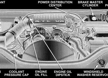
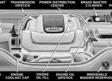
TO OPEN AND CLOSE THE HOOD To open the hood, pull the release lever inside your vehicle located below the instrument panel and in front of the driver’s door.
UNDERSTANDING THE FEATURES OF YOUR VEHICLE 123
Hood Release Handle
124 UNDERSTANDING THE FEATURES OF YOUR VEHICLE
Then, reach under the hood, move safety latch to the left, and lift the hood. To prevent possible damage, do not slam the hood to close it. Use a firm downward push at the center of the hood to ensure that both latches engage.
Underhood Safety Latch
WARNING!
If the hood is not fully latched, it could fly up when the vehicle is moving and block your forward vision. Be sure all hood latches are fully latched before driving.
LIGHTS
Multi-Function Control Lever The multi-function control lever controls the operation of the headlights, turn signals, headlight beam selection, instrument panel light dimming, passing light, interior courtesy/dome lights, and optional fog lights.
Battery Saver Feature—Exterior/Interior Lights If the multi-function control lever is left in the interior light position, parking light position, or the headlight position when the ignition switch is moved to the OFF position, the battery saver feature will automatically turn off the exterior and interior lights after eight minutes. Normal operation will resume when the ignition is turned ON or when the headlight switch is turned to another position. Headlights and Parking Lights Turn the end of the multi-function control lever to the first detent for parking light operation. Turn to the second detent for headlight operation. Turn to the third detent for “Auto” headlight operation (if equipped).
UNDERSTANDING THE FEATURES OF YOUR VEHICLE 125
Headlight Switch
126 UNDERSTANDING THE FEATURES OF YOUR VEHICLE
Automatic Headlight System — If Equipped Turn the end of the multi-function control lever to the third detent to activate the automatic headlight system. This system performs two functions. With the engine running and the multi-function control lever in the A (Auto) position, the headlights will turn on and off based on the surrounding light levels. Headlights On Automatically With Wipers If your vehicle is equipped with Automatic Headlights it also has this customer programmable feature. When your headlights are in the automatic mode, and the engine is running, they will automatically turn on when the wiper system is on. If your vehicle is equipped with a “Rain Sensitive Wiper System,” and it is activated, the headlights will automati- cally turn on after the wipers complete five wipe cycles within approximately 1 minute, and they will turn off
approximately four minutes after the wipers completely stop. Refer to “Windshield Wipers and Washers” in this section for more information. NOTE: When your headlights come on during the daytime, the instrument panel lights will automatically dim to the lower nighttime intensity. Refer to “Instru- ment Panel and Interior Lights” below for setting the instrument panel lights to full daytime intensity. SmartBeams — If Equipped The SmartBeam system provides increased forward light- ing at night by automating high beam control through the use of a digital camera mounted on the inside rearview mirror. This camera detects vehicle specific light and automatically switches from high beams to low beams until the approaching vehicle is out of view.
If the windshield or SmartBeam mirror is re- NOTE: placed, the SmartBeam mirror must be re-aimed to ensure proper performance. See your local authorized dealer. To Activate 1. Select “Auto Headlamp Low/High Beams? — Low/ High Beam.” Refer to “EVIC — Customer Programmable Features” in Section 4 of this manual. 2. Turn the end of the multi-function control lever to the A (Auto) headlight position. NOTE: This system will not activate until the vehicle is at or above 20 mph (32 km/h). To Deactivate 1. Pull back on the muti-function control lever to manu- ally deactivate the system (normal operation of high beams).
UNDERSTANDING THE FEATURES OF YOUR VEHICLE 127
2. Pull back on the multi-function control lever once again to re-activate the system. NOTE: Broken, muddy, or obstructed headlights and taillights of vehicles in the field of view will cause headlights to remain on longer (closer to the vehicle). Also, dirt, film, and other obstructions (sticker, toll box, etc.) on the windshield or camera lens will cause the system to function improperly. Instrument Panel and Interior Lights When the multi-function control lever is in the parklight, headlight, or A (Auto) position (if equipped), rotating the center portion of the lever up and down will increase and decrease the brightness (dimmer control) of the instru- ment panel lights. Full daytime brightness on all elec- tronic displays (odometer, overhead console, radio, and Automatic Climate Control (if equipped) is obtained by rotating the center portion of the control to the first detent above the dimmer range. Rotating the control to
128 UNDERSTANDING THE FEATURES OF YOUR VEHICLE
the second detent above the dimmer range turns the interior lights on. Rotating the control to the “Off” (extreme bottom) position disables all the interior lights, even when the doors and liftgate are open. While in the “Off” position the instrument panel lighting is at the lowest light level and may not be suitable for night driving. Daytime Running Lights — If Equipped The high beam headlights come on at a low intensity level whenever the engine is running, and the transmis- sion is not in the P (Park) position. The lights remain on until the ignition switch is turned OFF or the parking brake is engaged. The headlight switch must be used for normal night time driving.
Lights-On Reminder If the headlights or parking lights are on after the ignition is turned OFF, a chime will sound when the driver’s door is opened. Fog Lights — If Equipped
The fog light switch is located in the multi- function control lever. To activate the fog lights, turn on the park/turn lights, low beam headlights, or “Auto” headlights and pull out the end of the multi- function control lever. A light in the instrument cluster shows when the fog lights are on. NOTE: Turning on the high beam headlights turns off the fog lights. A front fog light is a lighting device providing illumina- tion forward of the vehicle under conditions of fog, rain, snow, or dust. Principally, the front fog light supplements the lower beam of a standard headlight system.
NOTE: Proper aim and adjustments of the front fog lights should be made to prevent excessive glare for other drivers. Turn Signals Move the multi-function control lever up or down and the arrows on each side of the instrument cluster will flash to show proper operation of the front and rear turn signal lights. You can signal a lane change by moving the lever partially up or down. Turn Signal Auto-Mode Tap the multi-function control lever once and the turn signal (left or right) will flash 3 times, and automatically turn off.
UNDERSTANDING THE FEATURES OF YOUR VEHICLE 129
High Beam Switch Push the multi-function control lever away from you to switch the headlights to high beam. Pull the lever to- wards you to switch the headlights back to low beam. Passing Light You can signal another vehicle with your headlights by lightly pulling the multi-function control lever toward the steering wheel. This will cause the headlights to turn on at high beam and remain on until the lever is released. Headlight Time Delay There is also a feature that delays turning off the vehicle lights for 30, 60, or 90 seconds after the ignition switch is turned OFF. To activate the headlight delay, the multi- function control lever must be rotated to the “Off” position after the ignition switch is turned OFF. Only the headlights will illuminate during this time. Refer to “EVIC- Customer Programmable Features” in Section 4
to turn this feature “On/Off” or set the time interval.130 UNDERSTANDING THE FEATURES OF YOUR VEHICLE
Interior Lights The interior lighting consists of courtesy lights mounted below the instrument panel, an overhead console light assembly which contains both driver and passenger reading lights, reading lights located above the rear doors, and a rear cargo light. Opening a door or turning the center of the multi-function control lever to the extreme up position will activate all interior courtesy lights. Courtesy/Reading Lights
Each light can be turned on by pressing the recessed area of the lens. To turn these lights off, press the recessed area of the lens a second time. There are also reading lights located above the rear doors. Each light can be turned on by pressing the front recessed area of the lens. To turn these lights off, press the recessed area of the lens a second time.
Courtesy/Reading Lights
WINDSHIELD WIPERS AND WASHERS The front and rear wipers and washers are operated by a switch in the right side control lever. Turn the end of the control lever to select “Lo,” “Hi,” or one of the five speed sensitive intermittent windshield wiper speeds. Refer to “Speed Sensitive Intermittent Wiper System” in this section. For information on the rear wiper and washer refer to “Rear Window Features” in this section.
UNDERSTANDING THE FEATURES OF YOUR VEHICLE 131
Windshield Wiper/Washer Switch
NOTE: Always remove any build-up of snow that prevents the windshield wiper blades from returning to the OFF position. If the windshield wiper switch is turned off and the blades cannot return to the OFF position, damage to the wiper motor may occur.
132 UNDERSTANDING THE FEATURES OF YOUR VEHICLE
To use the washer, pull the lever toward you and hold while spray is desired. If the lever is pulled while in the delay range, the wiper will operate for several seconds after the lever is released, and then resume the intermit- tent interval previously selected. If the lever is pulled while in the OFF position, the wipers will operate for several wipe cycles, then turn off.
WARNING!
Sudden loss of visibility through the windshield could lead to an accident. You might not see other vehicles or other obstacles. To avoid sudden icing of the windshield during freezing weather, warm the windshield with the defroster before and during windshield washer use.
Mist Use this feature when weather conditions make occa- sional usage of the wipers necessary. Pull down and release the control lever for a single wiping cycle. Speed Sensitive Intermittent Wiper System Use one of the five intermittent wiper speeds when weather conditions make a single wiping cycle, with a variable pause between cycles, desirable. Turn the end of the lever to one of the five delay positions for the desired delay interval. The delay can be regulated from a maxi- mum of approximately 18 seconds between cycles, to a cycle every 1/2 second. NOTE: The wiper delay times depend on vehicle speed. If the vehicle is moving less than 10 mph (16 km/h), delay times will be doubled.
Rain Sensing Wipers—If Equipped This feature senses moisture on the windshield and automatically activates the wipers for the driver. The feature is especially useful for road splash or overspray from the windshield washers of the vehicle ahead. Rotate the end of the multi-function lever to one of five settings to activate this feature. The sensitivity of the system can be adjusted with the multi-function lever. Wiper delay position 1 is the least sensitive, and wiper delay position 5 is the most sensi- tive. Setting 3 should be used for normal rain conditions. Settings 1 and 2 can be used if the driver desires less wiper sensitivity. Settings 4 and 5 can be used if the driver desires more sensitivity. Place the wiper switch in the OFF position when not using the system. NOTE: † The rain sensing feature will not operate when the wiper switch is in the LOW or HIGH speed position.
UNDERSTANDING THE FEATURES OF YOUR VEHICLE 133
may reduce rain sensor performance.
ice, or dried salt water is present on the windshield.
† The rain sensing feature may not function properly when † Use of Rain-Xt or products containing wax or silicone † A customer programmable feature in the Electronic Vehicle Information Center (EVIC) allows the Rain Sense feature to be turned off. Refer to “Electronic Vehicle Information Center (EVIC) — Customer Pro- grammable Features” in Section 4 of this manual.
The rain sensing system has protection features for the wiper blades and arms, and will not operate under the following conditions: † Low Ambient Temperature — When the ignition is first turned ON, the rain sensing system will not operate until the wiper switch is moved, vehicle speed is greater than 0 mph (0 km/h), or the outside tem- perature is greater than 32°F (0°C).
134 UNDERSTANDING THE FEATURES OF YOUR VEHICLE
† Transmission in N (Neutral) Position — When the ignition is ON, and the transmission is in the N (Neutral) position, the rain sensing system will not operate until the wiper switch is moved, vehicle speed is greater than 5 mph (8 km/h), or the shift lever is moved out of the N (Neutral) position.
TILT/TELESCOPING STEERING COLUMN This feature allows you to tilt the steering column upward or downward. It also allows you to lengthen or shorten the steering column. The tilt/telescoping control handle is located below the steering wheel at the end of the steering column.
Tilt Steering Column
To unlock the steering column, push the control handle downward (toward the floor). To tilt the steering column, move the steering wheel upward or downward as de- sired. To lengthen or shorten the steering column, pull the steering wheel outward or push it inward as desired. To lock the steering column in position, push the control handle upward until fully engaged.
WARNING!
Do not adjust the steering wheel while driving. The telescoping adjustment must be locked while driv- ing. Adjusting the steering wheel while driving or driving without the telescoping adjustment locked could cause the driver to lose control of the vehicle.
ADJUSTABLE PEDALS — IF EQUIPPED This feature allows both the brake and accelerator pedals to move toward the driver to provide improved position with the steering wheel. The adjustable pedal system is designed to allow a greater range of driver comfort for steering wheel tilt and seat position. The position of the brake and accelerator pedals can be adjusted without compromising safety or comfort in actuating the pedals.
UNDERSTANDING THE FEATURES OF YOUR VEHICLE 135
Adjustable Pedal Switch
Press the bottom of the switch to move the pedals rearward (toward the driver). Press the top of the switch to move the pedals forward (away from the driver).
136 UNDERSTANDING THE FEATURES OF YOUR VEHICLE
† The pedals can be adjusted with the ignition OFF. † The pedals can be adjusted while driving. † The pedals cannot be adjusted when the vehicle is in R (Reverse) or when the Speed Control is ON. A message will be displayed in the Electronic Vehicle Information Center (EVIC) if the pedals are attempted to be ad- justed when the system is locked out (“Adjustable Pedal Disabled — Cruise Control Engaged” or “Ad- justable Pedal Disabled — Vehicle In Reverse”). Refer to Electronic Vehicle Information Center (EVIC) in Section 4 for more information.
CAUTION!
Do not place any article under the adjustable pedal’s or impede its ability to move as it may cause damage to the pedal controls. Pedal travel may become lim- ited if movement is stopped by an obstruction in the adjustable pedal’s path.
ELECTRONIC SPEED CONTROL — IF EQUIPPED When engaged, this device takes over accelerator opera- tions at speeds greater than 30 mph (48 km/h) for 3.7L/ 4.7L engines, and 25 mph (40 km/h) for 5.7L engines. Electronic Speed Control Operation The speed control lever is located on the right side of the steering wheel.
UNDERSTANDING THE FEATURES OF YOUR VEHICLE 137
WARNING!
Leaving the Speed Control system on when not in use is dangerous. You could accidentally set the system or cause it to go faster than you want. You could lose control and have an accident. Always leave the system OFF when you are not using it.
To Set At A Desired Speed When the vehicle has reached the desired speed, press down on the lever and release. Release the accelerator and the vehicle will operate at the selected speed. NOTE: The vehicle should be traveling at a steady speed and on level ground before pressing the SET lever.
Electronic Speed Control Switch
To Activate Push the ON/OFF button. The CRUISE indicator in the instrument cluster will illuminate. To turn the system OFF, push the ON/OFF button a second time. The CRUISE indicator will turn off. The system should be turned OFF when not in use.
138 UNDERSTANDING THE FEATURES OF YOUR VEHICLE
To Deactivate A soft tap on the brake pedal, pulling the speed control lever towards you “CANCEL”, or normal brake or clutch pressure while slowing the vehicle will deactivate speed control without erasing the set speed memory. Pressing the ON/OFF button or turning off the ignition switch erases the set speed memory. To Resume Speed To resume a previously set speed, push the “RESUME ACCEL” lever up and release. Resume can be used at any speed above 30 mph (48 km/h) for 3.7L/4.7L engines, and 25 mph (40 km/h) for 5.7L engines. To Vary The Speed Setting When the speed control is ON, speed can be increased by pushing up and holding “RESUME ACCEL”. Release the lever when the desired speed is reached, and the new speed will be set.
Tapping “RESUME ACCEL” once will result in a 2 mph (3 km/h) (3.7L/4.7L models) or a 1 mph (2 km/h) (5.7L models) speed increase. Each time the lever is tapped, speed increases so that tapping the lever three times will increase speed by 6 mph (10 km/h) (3.7L/4.7L models) or 3 mph (5 km/h) (5.7L models). To decrease speed while speed control is ON, push down and hold “SET DECEL”. Release the lever when the desired speed is reached, and the new speed will be set. Tapping the “SET DECEL” button once will result in a 1
mph (2 km/h) speed decrease. Each time the button is tapped, speed decreases. NOTE: The Speed Control system has been designed to shut down if multiple speed control switch functions are operated simultaneously in order to ensure proper op- eration. If this occurs, the system can be reactivated by pushing the speed control switch ON/OFF button and re-setting the desired vehicle SET speed.To Accelerate For Passing Depress the accelerator as you would normally. When the pedal is released, the vehicle will return to the set speed. Using Speed Control On Hills The automatic transmission may downshift on hills to maintain the vehicle set speed. NOTE: The speed control system maintains speed up and down hills. A slight speed change on moderate hills is normal. On steep hills a greater speed loss or gain may occur so it may be preferable to drive without speed control.
UNDERSTANDING THE FEATURES OF YOUR VEHICLE 139
ELECTRONIC BRAKE CONTROL SYSTEM Your vehicle is equipped with an advanced electronic brake control system that includes ABS (Anti-Lock Brake System), TCS (Traction Control System), BAS (Brake Assist System), ERM (Electronic Roll Mitigation), and ESP (Electronic Stability Program). All five of these systems work together to enhance vehicle stability and control in various driving conditions. Also, your vehicle is equipped with TSC (Trailer Sway Control) and, if it has 4WD with the NV245 two-speed transfer case, HSA (Hill Start Assist) and HDC (Hill Descent Control). ABS (Anti-Lock Brake System)
This system aids the driver in maintaining vehicle control under adverse braking conditions. The system controls hydraulic brake pressure to prevent wheel lock-up and
140 UNDERSTANDING THE FEATURES OF YOUR VEHICLE
help avoid skidding on slippery surfaces during braking. Refer to “Anti-Lock Brake System” in Section 5 of this manual for more information about ABS.
WARNING!
ABS (Anti-Lock Brake System) cannot prevent the natural laws of physics from acting on the vehicle, nor can it increase the traction afforded by prevailing road conditions. ABS cannot prevent accidents, in- cluding those resulting from excessive speed in turns, driving on very slippery surfaces, or hydro- planing. Only a safe, attentive, and skillful driver can prevent accidents. The capabilities of an ABS- equipped vehicle must never be exploited in a reck- less or dangerous manner which could jeopardize the user’s safety or the safety of others.
TCS (Traction Control System)
This system monitors the amount of wheel spin of each of the driven wheels. If wheel spin is detected, brake pressure is applied to the slipping wheel(s) and engine power is reduced to provide enhanced acceleration and stability. A feature of the TCS system functions similar to a limited slip differential and controls the wheel spin across a driven axle. If one wheel on a driven axle is spinning faster than the other, the system will apply the brake of the spinning wheel. This will allow more engine torque to be applied to the wheel that is not spinning. This feature remains active even if TCS and ESP are in either the “Partial Off” or “Full Off” modes. Refer to “ESP (Electronic Stability Program)” in this section for more information.
BAS (Brake Assist System) The BAS is designed to optimize the vehicle’s braking capability during emergency braking maneuvers. The system detects an emergency braking situation by sens- ing the rate and amount of brake application and then applies optimum pressure to the brakes. This can help reduce braking distances. The BAS complements the anti-lock brake system (ABS). Applying the brakes very quickly results in the best BAS assistance. To receive the benefit of the system, you must apply continuous brak- ing pressure during the stopping sequence (do not “pump” the brakes). Do not reduce brake pedal pressure unless braking is no longer desired. Once the brake pedal is released, the BAS is deactivated.
UNDERSTANDING THE FEATURES OF YOUR VEHICLE 141
WARNING!
BAS (Brake Assist System) cannot prevent the natu- ral laws of physics from acting on the vehicle, nor can it increase the traction afforded by prevailing road conditions. BAS cannot prevent accidents, including those resulting from excessive speed in turns, driving on very slippery surfaces, or hydroplaning. Only a safe, attentive, and skillful driver can prevent acci- dents. The capabilities of a BAS-equipped vehicle must never be exploited in a reckless or dangerous manner which could jeopardize the user’s safety or the safety of others.
142 UNDERSTANDING THE FEATURES OF YOUR VEHICLE
ERM (Electronic Roll Mitigation) This system anticipates the potential for wheel lift by monitoring the driver’s steering wheel input and the speed of the vehicle. When ERM determines that the rate of change of the steering wheel angle and vehicles speed are sufficient to potentially cause wheel it then applies the brake of the appropriate wheel and may also reduce engine power to lessen the chance that wheel lift will occur. ERM will only intervene during very severe or evasive driving maneuvers. ERM can only reduce the chance of wheel lift occurring during severe or evasive driving maneuvers. It cannot prevent wheel lift due to other factors such as road conditions, leaving the roadway or striking objects or other vehicles.
lift,
NOTE: Anytime the ESP system is in the “Full Off” mode, ERM is disabled. Refer to ESP (Electronic Stability Program) for a complete explanation of the available ESP modes.
WARNING!
Many factors, such as vehicle loading, road condi- tions and driving conditions, influence the chance that wheel lift or rollover may occur. ERM cannot prevent all wheel lift or rollovers, especially those that involve leaving the roadway or striking objects or other vehicles. Only a safe, attentive, and skillful driver can prevent accidents. The capabilities of an ERM-equipped vehicle must never be exploited in a reckless or dangerous manner which could jeopar- dize the user’s safety or the safety of others.
ESP (Electronic Stability Program)
This system enhances directional control and stability of the vehicle under various driving conditions. ESP cor- rects for oversteering or understeering of the vehicle by applying the brake of the appropriate wheel to assist in counteracting the oversteer or understeer condition. En- gine power may also be reduced to help the vehicle maintain the desired path. ESP uses sensors in the vehicle to determine the vehicle path intended by the driver and compares it to the actual path of the vehicle. When the actual path does not match the intended path, ESP applies the brake of the appropri- ate wheel to assist in counteracting the oversteer or understeer condition.
UNDERSTANDING THE FEATURES OF YOUR VEHICLE 143
† Oversteer - when the vehicle is turning more than † Understeer - when the vehicle is turning less than
appropriate for the steering wheel position.
appropriate for the steering wheel position.
The 9ESP/TCS Indicator Light9 located in the instrument cluster, starts to flash as soon as the tires lose traction and the ESP system becomes active. The 9ESP/TCS Indicator Light9 also flashes when TCS is active. If the 9ESP/TCS Indicator Light9 begins to flash during acceleration, ease up on the accelerator and apply as little throttle as possible. Be sure to adapt your speed and driving to the prevailing road conditions.
144 UNDERSTANDING THE FEATURES OF YOUR VEHICLE
WARNING!
ESP (Electronic Stability Program) cannot prevent the natural laws of physics from acting on the vehicle, nor can it increase the traction afforded by prevailing road conditions. ESP cannot prevent accidents, in- cluding those resulting from excessive speed in turns, driving on very slippery surfaces, or hydro- planing. Only a safe, attentive, and skillful driver can prevent accidents. The capabilities of an ESP- equipped vehicle must never be exploited in a reck- less or dangerous manner which could jeopardize the user’s safety or the safety of others.
The ESP system has 3 available operating modes in 4WD High Range, 2 available operating modes on 2WD ve- hicles, and 1 operating mode in 4WD Low Range.
High Range (4WD Models) or 2WD Models
On This is the normal operating mode for ESP in 4WD high range and in 2WD vehicles. Whenever the vehicle is started or the transfer case (if equipped) is shifted from 4WD low range or neutral back to 4WD high range, the ESP system will be in this “On” mode. This mode should be used for most driving situations. ESP should only be turned to “Partial Off” or “Full Off” mode for specific reasons as noted below. Partial Off This mode is entered by momentarily depressing the 9ESP OFF” switch. When in 9Partial Off9 mode, the TCS portion of ESP, except for the “limited slip” feature described in the TCS section, has been disabled and the 9ESP/TCS Indicator Light9 will be illuminated. All other stability features of ESP function normally. This mode is intended to be used if the vehicle is in deep snow, sand,
or gravel conditions and more wheel spin than ESP would normally allow is required to gain traction. To turn ESP on again, momentarily depress the 9ESP OFF” switch. This will restore the normal “ESP On” mode of operation.
ESP OFF Switch
UNDERSTANDING THE FEATURES OF YOUR VEHICLE 145
NOTE: To improve the vehicle’s traction when driving with snow chains, or starting off in deep snow, sand, or gravel, it may be desirable to switch to the “Partial Off” mode by pressing the ESP switch. Once the situation requiring ESP to be switched to the “Partial Off” mode is overcome, turn ESP back on by momentarily depressing the “ESP OFF” switch. This may be done while the vehicle is in motion. Full Off (4WD Models Only) This mode is intended for off-highway or off-road use when ESP stability features could inhibit vehicle maneu- verability due to trail conditions. This mode is entered by depressing and holding the “ESP OFF” switch for 5
seconds when the vehicle is stopped and the engine is running. After 5 seconds, the “ESP/TCS Indicator Light” will illuminate, and the 9ESP OFF9 message will appear in the Electronic Vehicle Information Center (EVIC). Refer to “Electronic Vehicle Information Center (EVIC)” in Section 4 of this manual for more information.146 UNDERSTANDING THE FEATURES OF YOUR VEHICLE
In this mode, ESP and TCS, except for the “limited slip” feature described in the TCS section, are turned off until the vehicle reaches a speed of 40 mph (64 km/h). At 40
mph (64 km/h) the system returns to “Partial Off” mode, described above. When the vehicle speed drops below 35
mph (56 km/h) the ESP system shuts off. ESP is deacti- vated at low vehicle speeds so that it will not interfere with off-road driving but ESP function returns to provide the stability feature at speeds above 40 mph (64 km/h). The “ESP/TCS Indicator Light” will always be illumi- nated when ESP is off. To turn ESP on again, momen- tarily depress the “ESP OFF” switch. This will restore the normal “ESP On” mode of operation. NOTE: The “ESP OFF” message will display and the audible chime will sound when the gear selector is placed into the “P” (Park) position from any other position, and then moved out of the “P” (Park) position. This will occur even if the message was previously cleared.WARNING!
With the ESP switched off, the enhanced vehicle stability offered by ESP and ERM are unavailable. In an emergency evasive maneuver, the ESP and ERM systems will not engage to assist in maintaining stability. The “Full Off” ESP mode is intended for off-road use only.
4WD Low Range
Full Off This is the normal operating mode for ESP in 4WD low range. Whenever the vehicle is started in 4WD low range, or the transfer case (if equipped) is shifted from 4WD high range or neutral to 4WD low range, the ESP system will be in this “Full Off” mode. In 4WD low range, ESP and TCS, except for the “limited slip” feature described in the TCS section, are turned off until the vehicle reaches
a speed of 40 mph (64 km/h). At 40 mph (64 km/h), the normal ESP stability function returns but TCS remains off. When the vehicle speed drops below 35 mph (56
km/h), the ESP system shuts off. ESP is deactivated at low vehicle speeds in 4WD low range so that it will not interfere with off-road driving but ESP function returns to provide the stability feature at speeds above 40 mph (64 km/h). The 9ESP/TCS Indicator Light9 will always be illuminated in 4WD low range when ESP is off. NOTE: The “ESP OFF” message will display and the audible chime will sound when the gear selector is placed into the “P” (Park) position from any other position, and then moved out of the “P” (Park) position. This will occur even if the message was previously clearedUNDERSTANDING THE FEATURES OF YOUR VEHICLE 147
WARNING!
With the ESP switched off, the enhanced vehicle stability offered by ESP and ERM are unavailable. In an emergency evasive maneuver, the ESP and ERM systems will not engage to assist in maintaining stability. The “Full Off” mode is intended for off- road use only.
TSC (Trailer Sway Control) TSC uses sensors in the vehicle to recognize an exces- sively swaying trailer and will take the appropriate actions to attempt to stop the sway. The system may reduce engine power and apply the brake of the appro- priate wheel(s) to counteract the sway of the trailer. TSC will become active automatically once an excessively swaying trailer is recognized. No driver action is re- quired. Note that TSC cannot stop all trailers from
148 UNDERSTANDING THE FEATURES OF YOUR VEHICLE
swaying. Always use caution when towing a trailer and follow the tongue weight recommendations. Refer to “Trailer Towing” in Section 5 of this manual for more information on towing a trailer with your vehicle. When TSC is functioning, the “ESP/TCS Indicator Light” will flash, the engine power may be reduced and you may feel the brakes being applied to individual wheels to attempt to stop the trailer from swaying. TSC is disabled when the ESP system is in the Partial Off or Full Off modes.
WARNING!
If TSC activates while driving, slow the vehicle down, stop at the nearest safe location, and adjust the trailer load to eliminate trailer sway.
HSA (Hill Start Assist) (4WD Models with NV245
Two–Speed Transfer Case Only) The HSA system is designed to assist the driver when starting a vehicle from a stop on a hill. HSA will maintain the level of brake pressure the driver applied for a short period of time after the driver takes their foot off of the brake pedal. If the driver does not apply the throttle during this short period of time, the system will release brake pressure and the vehicle will roll down the hill. The system will release brake pressure in proportion to amount of throttle applied as the vehicle starts to move in the intended direction of travel.HSA Activation Criteria The following criteria must be met in order for HSA to activate: † Vehicle must be stopped. † Vehicle must be on a 8% grade or greater hill. † Gear selection matches vehicle uphill direction (i.e., vehicle facing uphill is in forward gear; vehicle back- ing uphill is in R (Reverse) gear).
UNDERSTANDING THE FEATURES OF YOUR VEHICLE 149
WARNING!
There may be situations on minor hills (i.e., less than 8%), with a loaded vehicle, or while pulling a trailer, when the system will not activate and slight rolling may occur. This could cause a collision with another vehicle or object. Always remember the driver is responsible for braking the vehicle.
HSA will work in R (Reverse) and all forward gears when the activation criteria have been met. The system will not activate if the vehicle is placed in N (Neutral) or P (Park).
Towing with HSA HSA will provide assistance when starting on a grade when pulling a trailer.
150 UNDERSTANDING THE FEATURES OF YOUR VEHICLE
WARNING!
† If you use a trailer brake controller with your trailer, your trailer brakes may be activated and deactivated with the brake switch. If so, when the brake pedal is released there may not be enough brake pressure to hold the vehicle and trailer on a hill and this could cause a collision with another vehicle or object behind you. In order to avoid rolling down the hill while resuming acceleration, manually activate the trailer brake prior to releas- ing the brake pedal. Always remember the driver is responsible for braking the vehicle. † HSA is not a parking brake. If you stop the vehicle on a hill without putting the transmission in P (Park) and using the parking brake, it will roll down the hill and could cause a collision with another vehicle or object. Always remember to use the parking brake while parking on a hill, and that the driver is responsible for braking the vehicle.
HSA Off If you wish to turn off the HSA system, it can be done using the Customer Programmable Features in the Elec- tronic Vehicle Information Center (EVIC). Refer to “Elec- tronic Vehicle Information Center (EVIC)” in Section 4 of this manual. HDC (Hill Descent Control) (4WD Models with NV245 Two–Speed Transfer Case Only) HDC maintains vehicle speed while descending hills during off-road driving situations and is available in 4
LOW range only. To enable HDC (transfer case must be in 4 LOW range), press the HDC switch. If the HDC switch is pressed when the vehicle is not in 4 LOW range, the light in the switch will flash for 5 seconds and HDC will not be enabled.UNDERSTANDING THE FEATURES OF YOUR VEHICLE 151
and will only activate when the vehicle is descending a hill. It will usually not activate on level ground. The HDC speed may be adjusted by the driver to suit the driving conditions. The speed corresponds to the trans- mission gear selected. † 1st = 1 mph (1.6 km/h) † 2nd = 2.5 mph (4 km/h) † 3rd = 4 mph (6 km/h) † 4th = 5.5 mph (9 km/h) † 5th = 7.5 mph (12 km/h) † Reverse (R) = 1 mph (1.6 km/h) † Neutral (N) = 2.5 mph (4 km/h) † Park (P) — HDC will not function
Hill Descent Switch
When HDC is enabled properly, the message “HILL DESCENT CONTROL” will appear in the EVIC and the light in the switch will be illuminated. HDC will auto- matically apply the brakes to control downhill speed when necessary. HDC has the capability to sense terrain
152 UNDERSTANDING THE FEATURES OF YOUR VEHICLE
HDC also has the capability to sense rough terrain, and will automatically adjust to a slightly slower set speed (about.3 mph (.5 km/h) than normal. HDC operation can be overridden with brake application to slow the vehicle down below the HDC control speed. Conversely, if more speed is desired during HDC control, the accelerator pedal will increase vehicle speed in the usual manner. When either the brake or the accelerator is released, HDC will control the vehicle back to the origi- nal set speed. HDC is intended for low speed off-road driving only. At vehicle speeds above 30 mph (48 km/h), HDC will no longer function. When the vehicle speed drops below 30
mph (48 km/h), HDC function will automatically resume and the vehicle speed will return to the chosen set speed.WARNING!
HDC is only intended to assist the driver in control- ling vehicle speed when descending hills. The driver must remain attentive to the driving conditions and is responsible for maintaining a safe vehicle speed.
ESP/BAS Warning Lamp and ESP/TCS Indicator Light
The malfunction indicator lamp for the ESP is combined with the BAS indicator. The yellow “ESP/BAS Warning Lamp” and the yellow “ESP/TCS Indicator Light” in the instrument cluster both come on when the ignition switch is turned to the “ON” position. They should both go out with the engine running.
If the “ESP/BAS Warning Lamp” comes on continuously with the engine running, a mal- function has been detected in either the ESP or the BAS system, or both. If this light remains on after several ignition cycles, and the vehicle has been driven several miles at speeds greater than 30 mph (48
km/h), see your authorized dealer as soon as possible to have the problem diagnosed and corrected. NOTE: † 9The 9ESP/TCS Indicator Light9 and the 9ESP/BAS Warning Lamp9 come on momentarily each time the ignition switch is turned ON. † Each time the ignition is turned ON, the ESP System † The ESP Control System will make buzzing or clicking sounds when it is active. This is normal; the sounds will stop when ESP becomes inactive following the maneuver that caused the ESP activation.will be ON even if it was turned off previously.
UNDERSTANDING THE FEATURES OF YOUR VEHICLE 153
REAR PARK ASSIST SYSTEM— IF EQUIPPED The Rear Park Assist System provides visual and audible indications of the distance between the rear fascia and the detected obstacle when backing up. Refer to the Warning Section and Note Section for limitations of this system and recommendations. The Rear Park Assist System will remember the last system state (enabled or disabled) from the last ignition cycle when the ignition is changed to the RUN/ON position. The Rear Park Assist System can be active only when the shifter is in R (Reverse). If the Rear Park Assist System is enabled at this shifter position, the system will be active until the vehicle speed is increased to approximately 11
mph (18 km/h) or above. The system will be active again if the vehicle speed is decreased to speeds less than approximately 10 mph (16 km/h).154 UNDERSTANDING THE FEATURES OF YOUR VEHICLE
Rear Park Assist Sensors The four Rear Park Assist Sensors, located in the rear fascia, monitor the area behind the vehicle that is within the sensors’ field of view. The monitored area seems oval in shape. The sensors can detect obstacles from approximately 11.8
inches (30 cm) up to 59 inches (150 cm) from the rear fascia in the horizontal direction, depending on the location and orientation of the obstacle and the type of obstacle. Rear Park Assist Warning Display The Rear Park Assist Warning Display, located in the headliner near the flipper glass, provides both visual and audible warnings to indicate the distance between the rear fascia and the detected obstacle.Rear Park Assist Display
When the ignition is changed to the RUN/ON position, the warning display will turn ON all of its LEDs for about 1 second. Each side of the warning display has 6
yellow and 2 red LEDs. The vehicle is close to the obstacle when the red LED is ON.UNDERSTANDING THE FEATURES OF YOUR VEHICLE 155
The system dimly illuminates the two outer most yellow LED’s when it is ON and detecting no obstacles. The following chart shows the warning display operation when the system is detecting an obstacle: WARNING DISPLAY DISTANCES
DISPLAY LED
OBSTACLE DISTANCE FROM:
LED COLOR
AUDIBLE SIGNAL
1st LED 2nd LED 3rd LED 4th LED 5th LED 6th LED 7th LED 8th LED
REAR CORNERS
31.5 in. (80 cm) 25.5 in. (65 cm) 20 in. (50 cm) 16 in. (40 cm) 6 in. (15 cm)
REAR CENTER 59 in. (150 cm) 51 in. (130 cm) 45 in. (115 cm) 39 in. (100 cm) 33.5 in. (85 cm) 28 in. (70 cm) 20 in. (50 cm) 12 in. (30 cm)
Yellow Yellow Yellow Yellow Yellow Yellow Red Red
None None None None None None
Yes, Intermittent Yes, Continuous
156 UNDERSTANDING THE FEATURES OF YOUR VEHICLE
NOTE: The Rear Park Assist system will MUTE the radio, if on, when the system is sounding an audio tone. Enable/Disable the Rear Park Assist System The Rear Park Assist System can be enabled and disabled with a switch located on the upper switch bank of the instrument panel.
Rear Park Assist Switch
When the switch is pressed to disable the system, the instrument cluster will display the 9PARK ASSIST DIS- ABLED9 message. Refer to “Electronic Vehicle Informa- tion Center (EVIC)” in Section 4 of this manual. When the shifter is changed to R (Reverse) and the system is disabled, the instrument cluster will actuate a single chime, once per ignition cycle, and it will display the message. The Rear Park Assist Switch LED will be ON when the Rear Park Assist System is disabled or defective. The Rear Park Assist Switch LED will be OFF when the system is enabled. Service the Rear Park Assist System When the Rear Park Assist System is defective, the instrument cluster will actuate a single chime, once per ignition cycle, and it will display the 9SERVICE PARK ASSIST SYSTEM9 message. Refer to “Electronic Vehicle Information Center (EVIC)” in Section 4 of this manual.
Cleaning the Rear Park Assist System Clean the Rear Park Assist Sensors with water, car wash soap and a soft cloth. Do not use rough or hard cloths. Do not scratch or poke the sensors. Otherwise, you could damage the sensors.
REAR CAMERA — IF EQUIPPED Vehicles with a Navigation radio may be equipped with a rear view camera (located on the rear liftgate) that allows you to see an on-screen image (on the navigation radio screen) of the rear of your vehicle whenever the vehicle is put into R (Reverse).
UNDERSTANDING THE FEATURES OF YOUR VEHICLE 157
WARNING!
Drivers must be careful when backing up even when using the rear camera system. Always check carefully behind your vehicle, and be sure to check for pedes- trians, animals, other vehicles, obstructions, or blind spots before backing up. Failure to do so can result in serious injury or death.
If snow, ice, mud, or anything else builds up on the camera lens. Clean the lens, rinse with water, and dry with a soft cloth. Turning the Rear Camera On
1. To access the rear camera mode, select “Rear Camera” at the Systems Settings screen and press ENTER. Refer to your “Navigation User’s Manual” for detailed operating instructions.
158 UNDERSTANDING THE FEATURES OF YOUR VEHICLE
2. Select “ON” at the “Rear Camera” screen. Highlight “DONE” and press ENTER. The rear camera is now enabled. 3. When the vehicle is shifted into R (Reverse), the CAUTION screen will appear, followed by an image of the rear of the vehicle. 4. When the vehicle is shifted out of R (Reverse), the rear camera mode is exited and the Navigation or Audio screen appears again. Turning the Rear Camera Off
1. To turn the rear camera off, select “Rear Camera” at the Systems Settings screen and press ENTER. Refer to your “Navigation User’s Manual” for detailed operating instructions. 2. Select “OFF” at the “Rear Camera” screen. Highlight “DONE” and press ENTER. The rear camera is now disabled.
OVERHEAD CONSOLE — IF EQUIPPED The overhead console contains an optional universal garage door opener (HomeLinkt), storage for sunglasses, and optional power sunroof switches.
Overhead Console
GARAGE DOOR OPENER — IF EQUIPPED HomeLinkt replaces up to three remote controls (hand held transmitters) that operate devices such as garage door openers, motorized gates, lighting, or home security systems. The HomeLinkt unit operates off of your vehi- cle’s battery. NOTE: HomeLinkt is disabled when the Vehicle Secu- rity Alarm is active.
UNDERSTANDING THE FEATURES OF YOUR VEHICLE 159
WARNING!
Your motorized door or gate will open and close while you are training the Universal Transceiver. Do not train the transceiver if people or pets are in the path of the door or gate. Only use this transceiver with a garage door opener that has a “stop and reverse” feature as required by federal safety stan- dards. This includes most garage door opener models manufactured after 1982. Do not use a garage door opener without these safety features. Call toll-free 1–800–355–3515
at www.HomeLink.com for safety information or assistance.Internet
the
on
or,
160 UNDERSTANDING THE FEATURES OF YOUR VEHICLE
WARNING!
Vehicle exhaust contains carbon monoxide, a danger- ous gas. Do not run your vehicle in the garage while training the transceiver. Exhaust gas can cause seri- ous injury or death.
Programming HomeLinkT
Before You Begin If you have not trained any of the HomeLinkt buttons, erase all channels before you begin training. To do this, press and hold the two outside buttons for 20
seconds. The EVIC will display “CLEARING CHAN- NELS.” Release the buttons when the EVIC message states “CHANNELS CLEARED.”It is recommended that a new battery be placed in the hand-held transmitter of the device being programmed to HomeLinkt for more efficient training and accurate transmission of the radio-frequency signal. Your vehicle should be parked outside of the garage while training. 1. Turn the ignition switch to the ON/RUN position. 2. Place the hand-held transmitter 1–3 inches (3–8 cm) from the HomeLinkt buttons while keeping the EVIC display in view. For optimal training, point the battery end of the hand- held transmitter away from the HomeLinkt. 3. Simultaneously press and hold both the chosen HomeLinkt button and the hand-held transmitter button until the EVIC display changes from “CHANNEL # TRAINING” to “CHANNEL # TRAINED.”
Then release both the HomeLinkt and hand-held trans- mitter buttons. If the EVIC display states “DID NOT TRAIN” repeat Step 3. If the signal is too weak, replace the battery in the original hand-held transmitter. It may take up to 30 seconds, or longer in rare cases. The garage door may open & close while you train. NOTE: Some gate operators and garage door openers may require you to replace Step #3 with procedures noted in the “Gate Operator/Canadian Programming” section. 4. Press and hold the just-trained HomeLinkt button. If the channel has been trained, the EVIC display will now state “CHANNEL # TRANSMIT.”
UNDERSTANDING THE FEATURES OF YOUR VEHICLE 161
If the EVIC display still states “CHANNEL # TRAIN- ING” repeat Step 3. NOTE: After training a HomeLinkt channel, if the garage door does not operate with HomeLinkt and the garage door opener was manufactured after 1995, the