- 2007 Hyundai Sonata Owners Manuals
- Hyundai Sonata Owners Manuals
- 2006 Hyundai Sonata Owners Manuals
- Hyundai Sonata Owners Manuals
- 2003 Hyundai Sonata Owners Manuals
- Hyundai Sonata Owners Manuals
- 2004 Hyundai Sonata Owners Manuals
- Hyundai Sonata Owners Manuals
- 2011 Hyundai Sonata Owners Manuals
- Hyundai Sonata Owners Manuals
- 2013 Hyundai Sonata Owners Manuals
- Hyundai Sonata Owners Manuals
- 2005 Hyundai Sonata Owners Manuals
- Hyundai Sonata Owners Manuals
- 2009 Hyundai Sonata Owners Manuals
- Hyundai Sonata Owners Manuals
- 2008 Hyundai Sonata Owners Manuals
- Hyundai Sonata Owners Manuals
- 2010 Hyundai Sonata Owners Manuals
- Hyundai Sonata Owners Manuals
- Download PDF Manual
-
mended when the filter is replaced.
F060J01A-AAT o Spark Plugs
The coolant should be changed at the intervals specified in the maintenance schedule.
F070D01A-AAT o Manual Transaxle Oil
Inspect the manual transaxle oil according to the maintenance schedule.
F070G02A-AAT o Brake Fluid
NOTE: If the oil level is low, check for possible leaks before adding oil. Do not overfill.
Make sure to install new spark plugs of the correct heat range.
F070E06A-AAT o Automatic Transaxle Fluid
F060N02E-AAT o Valve Clearance
Inspect excessive valve noise and/or engine vibration and adjust if necessary. A qualified technician should perform the operation.
The fluid level should be in the “HOT” range of the dipstick, after the engine and transaxle are at normal operating temperature. Check the automatic transaxle fluid level with the engine running and the transaxle in neutral, with the parking brake properly applied. Use HYUNDAI GENUINE ATF SP III, DIAMOND ATF SP III, SK ATF SP III or other brands meeting the SP III specification approved by Hyundai Motor Co. when adding or changing fluid. Using the wrong ATF may result in damage to the ATM.
F070F01A-AAT o Brake Hoses and Lines
Visually check for proper installation, chafing, cracks, deterioration and any leakage. Replace any deteriorated or damaged parts immedi- ately.
Check brake fluid level in the brake fluid reser- voir. The level should be between "MIN" and "MAX" marks on the side of the reservoir. Use only hydraulic brake fluid conforming to DOT 3
or DOT 4.F070H01A-AAT o Rear Brake Drums and Linings/
Parking Brake
Check the rear brake drums and linings for scoring, burning, leaking fluid, broken parts, and excessive wear. Inspect the parking brake system including the parking brake lever and cables. For detailed service procedures, refer to the Shop Manual.
VEHICLE MAINTENANCE REQUIREMENTS
F070Q01A-AAT o Air Conditioning Refrigerant
Check the air conditioning lines and connec- tions for leakage and damage. Check air con- ditioning performance according to the relevant shop manual if necessary.
F070J01A-AAT o Brake Pads, Calipers and Rotors
Check the pads for excessive wear, discs for run out and wear, and calipers for fluid leakage.
F070K01A-AAT o Exhaust Pipe and Muffler
Visually inspect the exhaust pipes, muffler and hangers for cracks, deterioration, or damage. Start the engine and listen carefully for any exhaust gas leakage. Tighten connections or replace parts as necessary.
F070L01A-AAT o Suspension Mounting Bolts
Check the suspension connections for loose- ness or damage. Retighten to the specified torque.
F070M01Y-AAT o Steering Gear Box, Linkage & Boots/ Lower Arm Ball Joint, Upper Arm Ball Joint
With the vehicle stopped and engine off, check for excessive free-play in the steering wheel. Check the linkage for bends or damage. Check the dust boots and ball joints for deterioration, cracks, or damage. Replace any damaged parts.
F070N01A-AAT o Power Steering Pump, Belt and Hoses
Check the power steering pump and hoses for leakage and damage. Replace any damaged or leaking parts immediately. Inspect the power steering belt for evidence of cuts, cracks, ex- cessive wear, oiliness and proper tension. Replace or adjust it if necessary.
F070P01A-AAT o Drive Shafts and Boots
Check the drive shafts, boots and clamps for cracks, deterioration, or damage. Replace any damaged parts and, if necessary, repack the grease.
DO-IT-YOURSELF MAINTENANCE
Engine Compartment .................................................... 6-2
General Checks ............................................................ 6-4
Checking the Engine Oil ............................................... 6-5
Changing the Engine Oil and Filter ................................ 6-6
Checking and Changing the Engine Coolant ................ 6-8
Spark Plugs ................................................................ 6-11
Changing the Air Cleaner Filter ................................... 6-14
Checking the Transaxle Oil (Manual) ......................... 6-17
Checking the Transaxle Fluid (Automatic) .................. 6-18
Checking the Brakes .................................................. 6-20
Air Conditioning Care .................................................. 6-21
Changing the Air Conditioner Filter ............................. 6-22
Checking Drive Belts .................................................. 6-24
Checking and Replacing Fuses .................................. 6-25
Checking the Battery .................................................. 6-27
Power Steering Fluid Level ......................................... 6-29
Headlight Aiming Adjustment ...................................... 6-30
Replacement of Light Bulbs ........................................ 6-31
Bulb Wattages ............................................................. 6-38
Fuse Panel Description ............................................... 6-396 DO-IT-YOURSELF MAINTENANCE
ENGINE COMPARTMENT
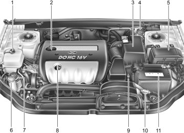
G010B01NF-AAT (2.4 DOHC)
CAUTION:
When inspecting or servicing the engine, you should handle tools and other heavy objects carefully so that the plastic cover of the engine is not damaged.
1. Coolant reservoir cap 2. Engine oil filler cap 3. Air cleaner 4. Brake fluid reservoir
5. Fuse and relay box 6. Windshield washer fluid reservoir 7. Power steering fluid reservoir 8. Engine oil level dipstick
G010B01NF
9. Automatic transaxle oil level
dipstick (If Installed)
10. Radiator cap 11. Battery
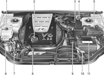
G010A01NF-AAT (3.3 V6)
DO-IT-YOURSELF MAINTENANCE
CAUTION:
When inspecting or servicing the engine, you should handle tools and other heavy objects carefully so that the plastic cover of the engine is not damaged.
1. Coolant reservoir cap 2. Engine oil filler cap 3. Air cleaner 4. Brake fluid reservoir
5. Fuse and relay box 6. Windshield washer fluid reservoir 7. Power steering fluid reservoir 8. Engine oil level dipstick
9. Automatic transaxle oil level dipstick 10. Radiator cap 11. Battery
G010A01NF
6 DO-IT-YOURSELF MAINTENANCE GENERAL CHECKS
G020A01NF-AAT Engine Compartment
G020B01A-AAT Vehicle Exterior
G020C01A-AAT Vehicle Interior
The following should be checked regularly:
The following should be checked monthly:
o Engine oil level and condition o Transaxle fluid level and condition o Brake fluid level o Engine coolant level o Windshield washer fluid level o Accessory drive belt condition o Engine coolant hose condition o Fluid leaks (on or below components) o Power steering fluid level o Battery condition o Air filter condition o Engine vibration
o Overall appearance and condition o Wheel condition and wheel nut torque o Exhaust system condition o Light condition and operation o Windshield glass condition o Wiper blade condition o Paint condition and body corrosion o Fluid leaks o Door and hood lock condition o Tire pressure and condition
(including spare tire)
The following should be checked each time when the vehicle is driven:
o Lights operation o Windshield wiper operation o Horn operation o Defroster, heating system operation (and air
conditioning, if installed)
o Steering operation and condition o Mirror condition and operation o Turn signal operation o Accelerator pedal operation o Brake operation, including parking brake o Manual transaxle operation, including clutch
operation
o Automatic transaxle operation, including
"Park" mechanism operation
o Seat control condition and operation o Seat belt condition and operation o Sun visor operation
If you notice anything that does not operate correctly or appears to be functioning correctly, inspect it carefully and seek assistance from your Hyundai dealer if service is needed.
CHECKING THE ENGINE OIL
G030A01A-AAT Engine oil is essential to the performance and service of the engine. It is suggested that you check the oil level at least once a week in normal use and more often if you are on a trip or driving in severe conditions.
G030B01O-AAT Recommended Oil
(3.3L)
NOTE: o For good fuel economy, SAE 5W-20 (5W- 30), ILSAC GF-3 engine oil is preferred regardless of regional option and en- gine variation.
o If SAE 5W-20, ILSAC GF-3 engine oil is not available, secondary recommended engine oil for corresponding tempera- ture range can be used.
DO-IT-YOURSELF MAINTENANCE
G030C01JM-AAT To Check the Oil Level (2.4L)
G030C02NF
Before checking the oil, warm up the engine to the normal operating temperature and be sure your car is parked on level ground. Turn the engine off.
Wait five minutes, then remove the dipstick, wipe it off, fully reinsert the dipstick and withdraw it again. Then note the highest level the oil has reached on the dipstick. It should be between the upper ("F") and lower ("L") range.
G030C01NF
WARNING:
Be very careful not to touch the radiator hose when checking the engine oil as it may be hot enough to burn you.
The engine oil quality should meet the following classification.
G030B01JM-U
API SJ, SL or ABOVE, ILSAC GF-3 or ABOVE
6 DO-IT-YOURSELF MAINTENANCE
G030D01O-AAT Adding Oil (2.4L)
(3.3L)
G030D01NF
G030D02NF If the oil level is close to or below the "L" mark, add oil until it reaches the "F" mark. To add oil:
1. Remove the oil filler cap by turning it counter-
2. Add oil, then check the level again. Do not
clockwise.
overfill.
3. Replace the cap by turning it clockwise.
The distance between the "F" and "L" marks is equal to about 1 quart of oil.
CAUTION:
Slowly pour the recommended oil into a funnel. Do not overfill to avoid damage to the engine.
WARNING:
Be very careful not to touch the radiator hose when adding the engine oil as it may be hot enough to burn you.
CHANGING THE ENGINE OIL AND FILTER G040A01NF-AAT (2.4L) Oil filler cap
(3.3L)
Oil filter
HNF5005
Oil filter
Oil filler cap Oil level dipstick
G040A01NF
The engine oil and filter should be changed at those intervals specified in the maintenance schedule in Section 5. If the car is being driven in severe conditions, more frequent oil and filter changes are required.
The procedure for changing the oil and filter is as follows:
DO-IT-YOURSELF MAINTENANCE
(2.4L)
1. Park the car on level ground and set the parking brake. Start the engine and let it warm up until the needle on the coolant temperature gauge moves above the lowest mark. Turn the engine off and place the gear selector lever in "P" (automatic) or reverse gear (manual transaxle).
2. Open the hood and remove the engine oil
filler cap.
NOTE: Loosen the oil filter cap by turning it coun- terclockwise to drain well the oil in the oil filter (3.3L only).
HNF5006-1
3. Slide underneath the car and loosen the drain plug by turning it counterclockwise with a wrench of the proper size. Be sure that a drain pan is in position to catch the oil as it drains out, then remove the drain plug.(3.3L)
WARNING:
Be very careful when draining the engine oil as it may be hot enough to burn you!
4. When the oil has stopped draining, replace the drain plug using a new gasket and re- tighten by turning it clockwise.
Oil pan drain plug tightening torque: 25.3 ~ 32.5 lb.ft (3.5 ~ 4.5 kgf.m)
HNF5005-1
G040B01NF
6 DO-IT-YOURSELF MAINTENANCE
5. Remove the oil filter by turning it counter- clockwise with a oil filter wrench of the proper size. A certain amount of oil will come out when you remove the filter. So be sure to have your drain pan in place underneath it. Install a new oil filter in accordance with the instructions on the carton or on the filter itself. Do not over-tighten.
6.
Tightening torque: 8.7 ~ 11.6 lb.ft (1.2 ~ 1.6 kgf.m)
Be sure that the mounting surface on the engine is clean and that the old gasket is removed completely. Lubricate the new gasket on the filter with clean engine oil before installation.
7. Remove the engine oil level dipstick. 8. Refill the crankcase with the recommended engine oil. Refer to the specification in chap- ter 9 for engine oil capacity.
NOTE: Always dispose of used engine oil in an environmentally acceptable manner. It is suggested that it be placed in a sealed container and taken to a service station for reclamation. Do not pour the oil on the ground or put it into the household trash.
PROPOSITION 65 WARNING: Used engine oil may cause irritation or cancer of the skin if left in contact with the skin for prolonged periods of time. Used engine oil contains chemicals that have caused cancer in laboratory animals. Al- ways protect your skin by washing your hands thoroughly with soap and warm water as soon as possible after handling used oil.
CHECKING AND CHANGING THE ENGINE COOLANT
G050A01A-AAT
WARNING:
Do not remove the radiator cap when the engine is hot. When the engine is hot, the engine coolant is under pressure and may erupt through the opening if the cap is removed. You could be seriously burned if you do not observe this precaution. Do not remove the radiator cap until the radiator is cool to the touch.
CAUTION:
Slowly pour the recommended oil into a funnel. Do not overfill to avoid damage to the engine.
9. Start the engine and check to be sure no oil
is leaking from the drain plug or oil filter.
10.Shut off the engine and recheck the oil level.
G050B01A-AAT Recommended Engine Coolant
G050C01NF-GAT To Check the Coolant Level
G050D01NF-GAT To Change the Engine Coolant
DO-IT-YOURSELF MAINTENANCE
Use a high quality ethylene-glycol coolant in a 50/50 mix with water. The engine coolant should be compatible with aluminum engine parts. Additional corrosion inhibitors or additives should not be used. The cooling system must be maintained with the correct concentration and type of engine coolant to prevent freezing and corrosion. Never allow the concentration of antifreeze to exceed the 60% level or go below the 35% level, or damage to the cooling system may result. For proper concentration when adding or replacing the engine coolant, refer to the following table.
Ambient
Engine Coolant concentration
temperature
°F (°C) 5 (-15) -13 (-25) -31 (-35) -49 (-45)
Antifreeze solution
35% 40% 50% 60%
Water
65% 60% 50% 40%
G050C01NF The coolant level can be seen on the side of the plastic coolant reservoir. The level of the cool- ant should be between the "L" and "F" lines on the reservoir when the engine is warm with it at idle . If the level is below the "L" mark, add engine coolant to bring it up to "F". If the level is low, inspect for coolant leaks and recheck the fluid level frequently. If the level drops again, visit your Hyundai dealer for an inspection and diagnosis of the reason.
The engine coolant should be changed at those intervals specified in the vehicle maintenance schedule in Section 5.
CAUTION:
o Engine coolant can damage the finish of your car. If you spill engine coolant on the car, wash it off thoroughly with clean water.
o The engine in your vehicle has alumi- num engine parts and must be protected by an ethylene-glycol base coolant to prevent corrosion and freezing. Do not use hard water. Hard water can cause engine damage from corrosion, overheating or freezing.
1. Park the car on level ground, set the parking brake and remove the radiator cap when cool.
6 DO-IT-YOURSELF MAINTENANCE 10
HNF5008
2. Wrap a thick cloth around the radiator cap and slowly turn the radiator cap counter- clockwise without pressing down on it, until it stops. This relieves any pressure remain- ing in the cooling system. When you are sure that all the pressure has been released, remove the radiator cap by pushing down and turning counterclockwise.
G050D02NF-A 3. Be sure your drain receptacle is in place. Open the drain cock on the radiator. Allow all the engine coolant to drain from the cooling system, and then securely close the drain cock.
4. Check Section 9 for the capacity of the cooling system in your car. Then, following the manufacturer's directions on the engine coolant container, add the appropriate quan- tity of coolant to the radiator.
5. Slowly fill the radiator with the proper coolant mixture (see the "Recommended Engine Coolant in previous page) until the fluid level stays up in the radiator neck. And pump the radiator hose in order to bleed the air.
G050D01NF 6. Run the engine at idle until the coolant circu- lates. If the cooling fan operates and the coolant starts to circulate, add the coolant to the reservoir.
7. To bleed the air in the cooling system, repeat procedure 6 until the cooling fan operates 3~5 times.
8. Replace the radiator cap and turn it until tightly installed. And then, add coolant to the reservoir until the level is between "L" and "F".
9. Stop the engine and check the coolant level when the engine is cool. The level of the coolant should be the "L" and "F" lines on the reservoir. If the level is below the "L" line, repeat the procedure 4~8 until the level between "L" and "F".
10.Replace the reservoir cap and check to be sure the drain cock and the radiator cap are fully closed and not leaking.
SPARK PLUGS
G060A01NF-AAT
CAUTION:
Recheck after a few days and add the cool- ant if the level is below the "L" level.
WARNING:
The cooling fan is controlled by engine coolant temperature and may sometimes operate even when the engine is not run- ning. Use extreme caution when working near the blades of the coolant fan so that you are not injured by a rotating fan blade. As the engine coolant temperature de- creases, the fan will automatically shut off. This is a normal condition.
G060A01L Your engine was originally equipped with Iri- dium-tipped spark plugs. Iridium-tipped spark plugs will last longer than conventional type spark plugs and can be identified by blue lines on the ceramic shell.
NOTE: Do not clean or regap Iridium-tipped spark plugs.
DO-IT-YOURSELF MAINTENANCE
11
G060B01NF-AAT Replacing the Spark Plugs
The spark plugs should be changed at the intervals specified in the vehicle maintenance schedule in Section 5 or whenever engine performance indicates they should be changed. Symptoms that suggest poor spark plug perfor- mance include engine misfiring under load, loss of fuel economy, poor acceleration, etc. When spark plugs are replaced, always use spark plugs recommended by Hyundai. The use of other spark plugs can result in loss of perfor- mance, radio interference or engine damage.
NOTE: When replacing the spark plugs, always use the genuine parts recommended.
Recommended Spark Plugs:
Type
SK16PR-A11
IFR5G-11Remark
2.4L 3.3L
6 DO-IT-YOURSELF MAINTENANCE 12
G060C01NF-GAT Changing the Spark Plugs
You will find it easier to change spark plugs if the engine is cold. Always change one spark plug at a time. This helps avoid getting the wires mixed up.
1. Remove the engine cover.
NOTE: It is recommended that the spark plugs for 3.3L engines be changed by an authorized Hyundai dealer.
2. Using a clean cloth, remove any dirt that has accumulated around the base of the spark plug so it cannot fall into the cylinder when the spark plug is removed.
G060C01NF 3. Remove the cover of the ignition connector
with a flat-head screwdriver.
(2)
(1)
G060C02NF 4. Pull the ignition connector key in the direction
of (1).
5. Press the position (2) of the ignition connec- tor key and detach the ignition connector by pulling it.
(3)
(4)
G060C03NF 6. Remove the mounting bolt (3) of the ignition
coil with a socket wrench.
7. Pull straight up on the ignition coil (4).
DO-IT-YOURSELF MAINTENANCE
13
G060C06NF
G060C05NF 10. To install the new spark plug, guide the socket down over the spark plug, being careful not to damage the ceramic insulator.
! WARNING:
It is recommended that the engine be cool or cold when changing the spark plugs. If the engine is hot, you could burn yourself on the insulated connector, the spark plug or the engine itself.
8. When preparing to remove the spark plug, guide the socket down over the spark plug, being careful not to damage the ceramic insulator.
9. To remove the spark plug, turn the wrench
handle in a counterclockwise direction.
6 DO-IT-YOURSELF MAINTENANCE 14
CHANGING THE AIR CLEANER FILTER
G070A03Y-AAT
CAUTION:
o Operating your vehicle without using a proper air cleaner filter in place can result in excessive engine wear.
o When removing the air cleaner filter, be careful that dust or dirt does not enter the air intake. These may result in dam- age to the air cleaner filter.
G060C04NF 11. Installation is the reverse order of disas-
sembly.
NOTE: Spark plugs should be tightened firmly. (Tightening torque: 18.0 lb.ft (2.5 kgf.m)) Over-tightening can damage the threads in the aluminum cylinder head. Also, leaving them too loose can cause the spark plug to get very hot and possibly result in damage to the engine.
HNF5011
The replacement of the air cleaner filter is performed in the following manner.1. Unsnap the clips around the cover. 2. When this is done, the cover can be lifted off, the old filter removed and the new filter put in its place.
Genuine Hyundai replacement parts are rec- ommended.
WINDSHIELD WIPER BLADES
G080A02A-AAT
G080B01HR-GAT Replacing the Wiper Blades
To replace the wiper blades, raise the wiper to the vertical position.
To remove the wiper blade
DO-IT-YOURSELF MAINTENANCE
15
2. Raise the wiper blade lightly and pull it up.
HHR5049
(1)
HHR5048
1. Push down the wiper blade with the locking clip (1) pressed to detach it from the wiper arm.G080A01NF-A The wiper blades should be carefully inspected from time to time and cleaned to remove accu- mulations of road film or other debris. To clean the wiper blades and arms, use a clean sponge or cloth with a mild soap or detergent and water. If the wipers continue to streak or smear the glass, replace them with genuine Hyundai re- placement parts or their equivalent.
CAUTION:
o Do not operate the wipers on dry glass. This can result in more rapid wear of the wiper blades and may scratch the glass. o Keep the blade rubber out of contact with petroleum products such as engine oil, gasoline, etc.
6 DO-IT-YOURSELF MAINTENANCE 16
To install the wiper blade
FILLING THE WASHER RESERVOIR
G090A02NF-AAT (2.4L)
HHR5050
1. Put a new wiper blade onto the wiper arm and lower the wiper blade at the level of the wiper arm as shown in the drawing.
2. Pull up the wiper blade until you hear an audible "click" to engage in the end of the wiper arm.
(3.3L)
HHR5051
NOTE: Do not allow the wiper arm to fall against the windshield.
G090A01NF
G090A02NF The washer fluid reservoir supplies fluid to the windshield washer system.
CHECKING THE TRANSAXLE OIL (MANUAL)
G100A01NF-AAT
DO-IT-YOURSELF MAINTENANCE
17
WARNING:
It is always better to check the transaxle oil level when the engine is cool or cold. If the engine is hot, you should exercise great caution to avoid burning yourself on hot engine or exhaust parts.
Drain plug
Filler plug
HNF5010
Transaxle lubricant in the manual transaxle should be checked at those intervals specified in the vehicle maintenance schedule in Section 5.Recommended Oil
Use only HYUNDAI GENUINE PARTS MTF 75W/85 (API GL-4) in the manual transaxle.
Manual Transaxle Oil Capacity
The oil capacity of the manual transaxle is 2.0
U.S. quarts (1.9 liters).A good quality washer fluid should be used to fill the washer reservoir. The fluid level should be checked more frequently during bad weather or whenever the washer system is in more fre- quent use. The capacity of the washer reservoir is 3.2 U.S. quarts (4.0 liters).
CAUTION:
o Radiator antifreeze (engine coolant) should not be used in the washer system because it will damage the car's finish. o The washer lever should not be pulled and the washer should not be operated if the washer reservoir is empty. This can damage the washer fluid pump.
WARNING:
o Windshield washer fluid agents contain some amounts of alcohol and can be flammable under certain circumstances. Do not allow sparks or flame to contact the washer fluid or the washer fluid reservoir. Damage to the vehicle or its occupants could occur.
o Windshield washer fluid is poisonous to humans and animals. Do not drink wind- shield washer fluid. Serious injury or death could occur.
6 DO-IT-YOURSELF MAINTENANCE 18
G100B02A-AAT To Check the Manual Transaxle Fluid Level
G100B01L Park the car on level ground with the engine off.
CHECKING THE TRANSAXLE FLUID (AUTOMATIC)
G110A01E-AAT Transaxle fluid in the automatic transaxle should be checked at those intervals specified in the vehicle maintenance schedule in Section 5.
NOTE: Automatic transaxle fluid is basically red in color. As driving distance increases, the fluid color turns darkish red gradually. It is a normal condition and you should not judge the need to replace based upon the changing color. You must replace the automatic transaxle fluid in accordance with intervals specified in the vehicle maintenance schedule in section 5.
1. Using a wrench of the correct size, loosen the oil filler plug by turning it counterclock- wise and remove it with your fingers.
2. Use your finger to feel inside the hole. The oil level should be at its bottom edge. If it is not, check for leaks before adding oil. To refill the transaxle or bring the oil level up, add oil slowly until it reaches the proper level. Do not overfill.
3. Replace the plug and washer, screw it in with your fingers and then tighten securely with the wrench.
G110B05A-AAT Recommended Fluid Your Hyundai automatic transaxle is specially designed to operate with HYUNDAI GENUINE ATF SP III, DIAMOND ATF SP III, SK ATF SP III or other brands meeting the SP III specifica- tion approved by Hyundai Motor Co.. Damage caused by a nonspecified fluid is not covered by your new vehicle limited warranty.
CAUTION:
Use of aftermarket ATF additives may cause damage to the automatic transaxle. Only use HYUNDAI GENUINE ATF SP III, DIAMOND ATF SP III, SK ATF SP III or other brands meeting the SP III specification ap- proved by Hyundai Motor Co.. If you are having your vehicle serviced at a facility other than a Hyundai dealer, verify that the correct ATF is used for your vehicle.
2.4L
3.3L
G110C01NF-AAT Transaxle Fluid Capacity
The fluid capacity of the automatic transaxle is:
8.24 U.S. quarts (7.8 liters)
11.52 U.S. quarts (10.9 liters)
WARNING:
The transaxle fluid level should be checked when the engine is at normal operating temperature. This means that the engine, radiator, radiator hose, exhaust system etc., are very hot. Exercise great care not to burn yourself during this procedure.
DO-IT-YOURSELF MAINTENANCE
19
G110D01NF
2. Remove the transaxle dipstick, wipe it clean, reinsert the dipstick as far as it will go, then remove it again. Now check the fluid level on the dipstick. It should be in the "HOT" range on the dipstick.
G110D02O-AAT To Check the Transaxle Fluid Level
Park the car on level ground with the parking brake engaged. When the transaxle fluid level is checked, the transaxle fluid should be at normal operating temperature and the engine idling.
C090F02NF
While the engine is idling, apply the brakes and move the gear selector lever from "P" to each of its other positions — "R", "N", "D" — and then return to "N" or "P". With the engine still idling:
1. Open the hood, being careful to keep hands, long hair and clothing clear of any moving parts.
6 DO-IT-YOURSELF MAINTENANCE 20
CHECKING THE BRAKES
G120A01A-AAT
CAUTION:
Because brakes are essential to the safe operation of the car, it is suggested that they be checked and inspected by your Hyundai dealer. The brakes should be checked and inspected for wear at those intervals specified in the vehicle mainte- nance schedule in Section 5.
G120B01A-AAT Checking the Brake Fluid Level
WARNING:
Use caution when handling brake fluid. It can damage your vision if it gets into your eyes. It will also damage your vehicle's paint if spilled on it and not removed imme- diately.
Fluid level should be within "HOT" range
3.
G110D02NF If the transaxle fluid level is low, use a funnel to add transaxle fluid through the dipstick tube until the level reaches the "HOT" range. Do not overfill.
WARNING:
The cooling fan is controlled by engine coolant temperature and may sometimes operate even when the engine is not run- ning. Use extreme caution when working near the blades of the cooling fan so that you are not injured by a rotating fan blade. As the engine coolant temperature de- creases, the fan will automatically shut off. This is a normal condition.
G120C02A-AAT Recommended Brake Fluid
Use only hydraulic brake fluid conforming to DOT 3 or DOT 4 specifications in your braking system. Follow the instructions printed on the container.
G120D01A-AAT To Check the Fluid Level
The fluid level in the brake fluid reservoir should be checked periodically. The level should be between the "MIN" and "MAX" marks on the side of the reservoir. If the level is at or below the "MIN" mark, carefully add fluid to bring it up to "MAX". Do not overfill.
AIR CONDITIONING CARE
DO-IT-YOURSELF MAINTENANCE
21
G120E02A-AAT Adding Brake Fluid
G140A01A-AAT Keeping the Condenser Clean
G140C01A-AAT Lubrication
The air conditioning condenser (and engine radiator) should be checked periodically for accumulation of dirt, dead insects, leaves, etc. These can interfere with maximum cooling ef- ficiency. When removing such accumulations, brush or hose them away carefully to avoid bending the cooling fans.
To lubricate the compressor and the seals in the system, the air conditioning should be run for at least 10 minutes each week. This is particularly important during cool weather when the air conditioning system is not otherwise in use.
G140B01A-AAT Checking the Air Conditioning Opera- tion
1. Start the engine and let it run at a fast idle for several minutes with the air conditioning set at the maximum cold setting. If the air coming out of the in-dash vents is not cold, have the air conditioning system inspected by your Hyundai dealer.
2.
CAUTION:
Running the air conditioning system for extended periods of time with a low refrig- erant level may damage the compressor.
HNF5013
WARNING:
Handle brake fluid carefully. It can damage your vision if it gets into your eyes. Use only DOT 3 or DOT 4 specification fluid from a sealed container. Do not allow the fluid can or reservoir to remain open any longer than required. This will prevent entry of dirt and moisture which can damage the brake sys- tem and cause improper operation.
To add brake fluid, first wipe away any dirt then unscrew the fluid reservoir cap. Slowly pour the recommended fluid into the reservoir. Do not overfill. Carefully replace the cap on the reser- voir and tighten.
6 DO-IT-YOURSELF MAINTENANCE CHANGING THE AIR 22
CONDITIONER FILTERB145A01NF-AAT (For Evaporator and Blower Unit) (If Installed)
The air conditioner filter is located in the right side of the instrument panel. It helps to decrease the amount of pollutants entering the car.
HNF2163-1
1. Remove the cover (1) which is located to the right side of the instrument panel by pulling it.
2. Pull the glove box cylinder (2) to unlock the
glove box retainer.
3. Lower the glove box down completely by pushing both sides of the glove box inward.
HNF2163
HNF2164
4. Remove the air conditioner filter cover bypressing both side clips.
CAUTION:
Be careful not to damage filter fixing clips.
CHECKING THE FREE-PLAY
DO-IT-YOURSELF MAINTENANCE
23
G150A01A-AAT STEERING WHEEL
G160A01A-GAT CLUTCH PEDAL
1.18 in. (30 mm)
0.24~0.51 in. (6~13 mm)
HNF5018
To check the steering wheel free-play, stop the car with the wheels pointed straight ahead and gently move the steering wheel back and forth. Use very light finger pressure and be sensitive to changes in resistance that mark the limits of the free-play. If the free-play is greater than specified, have it inspected by your Hyundai dealer and adjusted or repaired if necessary.G160A01HR With the engine off, press lightly on the clutch pedal until you feel a change in resistance. This is the clutch pedal free-play. The free-play should be within the limits specified in the illus- tration. If it is not, have it inspected by your Hyundai dealer and adjusted or repaired if necessary.
HNF2165
5. Replace the air conditioner filter by lifting it. Installation is the reverse order of disassem- 6. bly.
CAUTION:
To prevent pollutants from entering the car, be sure to properly install the air condi- tioner filter.
6 DO-IT-YOURSELF MAINTENANCE 24
G170A01A-AAT BRAKE PEDAL
CHECKING BRAKE PEDAL CLEARANCE
G180A01A-AAT
CHECKING DRIVE BELTS
G190A02NF-GAT
(2.4L)
Power steering Auto tensioner
0.12 ~ 0.31 in. (3 ~ 8 mm)
2.95 in. (75 mm)
Water pump pully
G160A01HR
With the engine off, press down on the brake pedal several times to reduce the vacuum in the brake booster. Then, using your hand, press down slowly on the brake pedal until you feel a change in resistance. This is the brake pedal free-play. The free-play should be within the limits speci- fied in the illustration above. If it is not, have it inspected by your Hyundai dealer and adjusted or repaired if necessary.
G180A01L You need a helper to check the brake pedal clearance. With the engine running, have your helper press down on the brake pedal several times and then hold it down with a force of about 110 lbs (50 kg, 490 N). The brake pedal clear- ance is the distance from the top surface of the brake pedal to the asphalt sheeting under the floor mat. If the brake pedal clearance is not within the limits specified in the illustration, have it in- spected by your Hyundai dealer and adjusted or repaired if necessary.
Generator
COMP
G140D01NF
Generator
Damper pulley
(3.3L)
Water pump pully
Auto tensioner
Power steering
Damper pulley
COMP
G140D02NF
CHECKING AND REPLACING FUSES G200A01A-AAT Replacing a Fusible Link
DO-IT-YOURSELF MAINTENANCE
25
CAUTION:
When replacing a fusible link, never use anything but a new fusible link with the same or lower amperage rating. Never use a piece of wire or a higher-rated fusible link. This could result in serious damage and create a fire hazard.
Drive belts should be checked periodically for proper tension. At the same time, belts should be examined for cracks, wear, fraying or other evidence of deterioration and replaced if neces- sary. When a new belt is replaced, the belt should be located within the pulley of flat idler. Belt routing should also be checked to be sure there is no interference between the belts and other parts of the engine.
NOTE: Drive belt tension is adjusted automatically by the auto tensioner.
HNF4004
A fusible link will melt if the electrical circuits from the battery are ever overloaded, thus prevent- ing damage to the entire wiring harness. (This could be caused by a short in the system drawing too much current.) If this ever happens, have a Hyundai dealer determine the cause, repair the system and replace the fusible link. The fusible links are located in a relay box in the engine compartment for easy inspection.6 DO-IT-YOURSELF MAINTENANCE 26
G200B01NF-GAT Replacing Accessory Fuse
2. Open the fuse box and examine each fuse. Remove each fuse by pulling it toward you (a small "fuse puller" tool is contained in the relay and fuse box of the engine room to simplify this operation).
3. Be sure to check all other fuses even if you
G200B01NF-A
The fuse box for the lights and other electrical accessories will be found on the left side of the instrument panel. Inside the box you will find a list showing the circuits protected by each fuse. If any of your car's lights or other electrical accessories stop working, a blown fuse could be the reason. If the fuse has burned out, you will see that the metal strip inside the fuse has burned through. If you suspect a blown fuse, follow this procedure: 1. Turn off the ignition and all other switches.
G200B02NF
find one that appears to have burned out. 4. Replace the blown fuse by pressing a new fuse of the same rating into place. The fuse should be a snug fit. If it is not, have the fuse clip repaired or replaced by a Hyundai dealer. If you do not have a spare fuse, you may be able to borrow a fuse of the same or lower rating from an accessory you can tempo- rarily get along without (the radio or cigarette lighter, for example). Always remember to replace the borrowed fuse.
Good
Burned out
G200B02L
CAUTION:
A burned-out fuse indicates that there is a problem in the electrical circuit. If you re- place a fuse and it blows as soon as the accessory is turned on, the problem is serious and should be referred to a Hyundai dealer for diagnosis and repair. Never re- place a fuse with anything except a fuse with the same or a lower amperage rating. A higher capacity fuse could cause damage and create a fire hazard.
NOTE: See page 6-39 for the fuse panel descrip- tions.
CHECKING THE BATTERY
G210A01A-AAT
HNF5017
WARNING:
Batteries can be dangerous! When working with batteries, carefully observe the follow- ing precautions to avoid serious injuries.
The fluid in the battery contains a strong solution of sulfuric acid, which is poisonous and highly corrosive. Be careful not to spill it on yourself or the car. If you do spill battery fluid on yourself, immediately do the following:
DO-IT-YOURSELF MAINTENANCE
27
o If battery fluid is on your skin, flush the affected areas with water for at least 15
minutes and then seek medical assistance. o If battery fluid is in your eyes, rinse out your eyes with water and get medical assistance as soon as possible. While you are being driven to get medical assistance, continue to rinse your eyes by using a sponge or soft cloth saturated with water.o If you swallow battery fluid, drink a large quantity of water or milk followed by milk of magnesia, eat a raw egg or drink vegetable oil. Get medical assistance as soon as possible.
While batteries are being charged (either by a battery charger or by the vehicle's generator), they produce explosive gases. Always ob- serve these warnings to prevent injuries from occurring:
G210B04A-AAT Checking the Battery
Keep the battery clean. Any evidence of corro- sion around the battery posts or terminals should be removed using a solution of house- hold baking soda and warm water. After the battery terminals are dry, cover them with a light coating of grease.
PROPOSITION 65 WARNING: Battery posts, terminals, and related acces- sories contain lead and lead compounds, chemicals known to the state of California to cause cancer and reproductive harm. Batteries also contain other chemicals known to the state of California to cause cancer. Wash hands after handling.
o Charge batteries only in a well ventilated
o Do not permit flames, sparks or smoking in
area.
the area.
o Keep children away from the area.
6 DO-IT-YOURSELF MAINTENANCE 28
WARNING: Always read the following in- structions carefully when han- dling a battery.
Keep lighted cigarettes and all other flames or sparks away from the battery.
Hydrogen, which is a highly com- bustible gas, is always present in battery cells and may explode if ignited.
Keep batteries out of the reach of children because batteries con- tain highly corrosive SULFURIC ACID. Do not allow battery acid to contact your skin, eyes, cloth- ing or paint finish.
If any electrolyte gets into your eyes, flush your eyes with clean water for at least 15 minutes and get immediate medical attention. If possible, continue to apply water with a sponge or cloth until medical attention is received.
WARNING: If electrolyte gets on your skin, thoroughly wash the contacted area. If you feel a pain or a burning sensation, get medical attention immediately.
Wear eye protection when charg- ing or working near a battery. Always provide ventilation when working in an enclosed space.
o When lifting a plastic-cased battery, ex- cessive pressure on the case may cause battery acid to leak, resulting in personal injury. Lift with a battery carrier or with your hands on opposite corners.
o Never attempt to charge the battery when
the battery cables are connected.
o The electrical ignition system works with
high voltage. Never touch these components with the engine running or the ignition switched on.
CHECKING ELECTRIC COOLING FANS G220A01A-AAT
WARNING:
The cooling fan is controlled by engine coolant temperature and may sometimes operate even when the engine is not run- ning. Use extreme caution when working near the blades of the cooling fan, so that you are not injured by a rotating fan blade. As the engine coolant temperature de- creases the fan will automatically shut off. This is a normal condition.
G220B01NF-GAT Checking Engine Cooling Fan
The engine cooling fan should come on auto- matically if the engine coolant temperature is high or whenever the air conditioning is in operation.
POWER STEERING FLUID LEVEL
G230A03A-AAT (2.4L)
29
DO-IT-YOURSELF MAINTENANCE
FOR MORE INFORMATION ABOUT YOUR HYUNDAI
G250A01A-AAT If you desire additional information about main- taining and servicing your Hyundai, you may purchase a factory Shop Manual at your Hyundai dealer's parts department. This is the same manual used by dealership technicians and while it is highly technical it can be useful in obtaining a better understanding of your car and how it works.
to make certain that the power steering fluid level is between the "MAX" and "MIN" level markings on the fluid reservoir.
NOTE: Grinding noise from the power steering pump may be heard immediately after the engine is started in extremely cold condi- tions (below - 4°F). If the noise stops during warm up, there is no abnormal function in the system. It is due to a power steering fluid characteristic in extremely cold condi- tions.
(3.3L)
G230A01NF
Recommended Fluid Use PSF-3 type fluid
NOTE: Do not start the engine when the power steering oil reservoir is empty.
G240A01A-AAT POWER STEERING HOSES
It is suggested that you check the power steer- ing hose connections for fluid leakage at those intervals specified in the vehicle maintenance schedule in Section 5. The power steering hoses should be replaced if there is severe surface cracking, pulling, scuffing or worn spots. Deterioration of the hose could cause premature failure.
G230A02NF The power steering fluid level should be checked regularly. To check the power steering fluid level, be sure the engine is "OFF", then check
6 DO-IT-YOURSELF MAINTENANCE 30
HEADLIGHT AIMING ADJUSTMENT
G290A02O-AAT Before performing aiming adjustment, make sure of the following. 1. Keep all tires inflated to the correct pressure. 2. Place the vehicle on level ground and press the front bumper & rear bumper down sev- eral times. Place vehicle at a distance of 118 in. (3m) from the test wall.
3. See that the vehicle is unloaded (except for full levels of coolant, engine oil and fuel, and spare tire, jack, and tools). Have the driver or equivalent weight placed in driver's seat. 4. Clean the headlight lenses and turn on the
headlights (Low beam).
5. Open the hood.
Vertical aiming
G290A01NF-A
6. Draw a vertical line (through the center of each headlight beam pattern) and a horizon- tal line (through the center of each headlight beam pattern) on the aiming screen. And then, draw a parallel line at 0.8 in. (21
mm) under the horizontal line.7. Adjust each cut-off line of the low beam to the parallel line with a phillips screwdriver - VERTICAL AIMING.
WARNING:
Horizontal aiming should be adjusted by an authorized Hyundai dealer.
G290B01NF-AAT Adjustment After Headlight Assembly Replacement
0.8 in.(21 mm)
Vertical line
Horizontal line
"P"
Cut-off line
Ground line
G260B01GK If the vehicle has had front body repair and the headlight assembly has been replaced, the headlight aiming should be checked using the aiming screen as shown in the illustration. Turn on the headlight switch (Low Beam Position). 1. Adjust headlights so that main axis of light is parallel to the center line of the body and is aligned with point "P" shown in the illustration. 2. Dotted lines in the illustration show the center
of the headlights.
SPECIFICATION: "H" Horizontal center line of headlights from ground : 26.73 in. (679mm)
"W" Distance between each headlight center : 51.41 in. (1,306mm)
"L" Distance between the headlights and the wall that the lights are tested against : 118.11 in. (3,000 mm)
REPLACEMENT OF LIGHT BULBS
G260A01L-GAT Before attempting to replace a light bulb, be sure the switch is turned to the "OFF" position. The next paragraph shows how to reach the light bulbs so they may be changed. Be sure to replace the burned-out bulb with one of the same number and wattage rating. See page 6-38 for the wattage descriptions.
DO-IT-YOURSELF MAINTENANCE
31
G270A01NF-AAT HEADLIGHT, FRONT TURN SIGNAL LIGHT AND FRONT FOG LIGHT
Headlight and Front Turn Signal Light
Headlight (High beam)
Headlight (Low beam)
CAUTION:
o Keep the lights out of contact with pe- troleum products, such as oil, gasoline, etc.
o Be sure to replace the LED type equipped
bulbs with an assembly.
Front Fog Light
Turn signal light (Front position light)
G260A01NF-A
Replacement instructions:
1. Allow the bulb to cool. Wear eye protection. 2. Open the engine hood. 3. Always grasp the bulb by its plastic base,
avoid touching the glass.
6 DO-IT-YOURSELF MAINTENANCE 32
5. Disconnect the power cord from the back of
the headlight.
HNF5023
4. Using a socket wrench of the correct size, remove the headlight assembly mounting bolts.HNF5025
6. Turn the plastic cover counterclockwiseand remove it.
HNF5024
HNF5026
7. Disconnect the connector from the bulb base in
the back of the headlight.
8. Push the bulb spring to remove the headlight
bulb.
HNF5027
9. Remove the protective cap from the re- placement bulb and install the new bulb by matching the plastic base with the headlight hole. Reattach the bulb spring and recon- nect the connector.10. Use the protective cap and carton to
promptly dispose of the old bulb. 11. Check for proper headlight aim.
! WARNING:
This halogen bulb contains gas under pres- sure and if impacted could shatter, result- ing in flying fragments. Always wear eye protection when servicing the bulb. Protect the bulb against abrasions or scratches and against liquids when lighted. Turn the bulb on only when installing in a headlight. Replace the headlight if damaged or cracked. Keep the bulb out of the reach of children and dispose of the used bulb with care.
HNF5028
12. To replace the front turn signal light bulb (front position light), remove it from the bulb holder and install the new bulb.
Front Fog Light
NOTE: It is recommended that the front fog light bulb should be replaced by an authorized Hyundai dealer.
G270A03O
DO-IT-YOURSELF MAINTENANCE
33
G270D01NF-AAT REAR COMBINATION LIGHT
Stop/Tail Light, Rear Turn Signal Light, Back-up Light and Rear Side Marker Light
1. Open the trunk lid.
2. Remove the cover on the inside of the rear luggage trim by turning the knob counter- clockwise.
HNF5029
6 DO-IT-YOURSELF MAINTENANCE 34
HNF5030-A
HNF5042
3. To replace the rear combination light (stop/ tail light, rear side marker light and rear turn signal light), remove it from the bulb holder and install the new bulb.
(1) Stop/tail light (2) Rear side marker light (3) Rear turn signal light
4. Loosen the mounting screws of the trunk lid trim with a phillips screwdriver and remove the trunk lid trim.
5. To replace the rear combination light (back- up light and stop/tail light), remove the socket by turning it counterclockwise. Install the new bulb.
6.
G270C01L-AAT LUGGAGE COMPARTMENT LIGHT
1. Open the trunk lid.
HNF5031
2. Remove the luggage compartment light cover on the rear package tray panel with a flat- head screwdriver.
DO-IT-YOURSELF MAINTENANCE
35
G270G01L-AAT INTERIOR LIGHT
Screwdriver
3. Disconnect the power cord.
HNF5032
HNF5034
2. Replace with a new bulb.
HNF5035
1. Remove the plastic cover with a flat-head
screwdriver.
4. Replace with a new bulb.
HTB284
6 DO-IT-YOURSELF MAINTENANCE 36
G270L01L-AAT MAP LIGHT
G270K01L-AAT GLOVE BOX ILLUMINATED LIGHT
1. Open the glove box.
1. Remove the plastic cover with a flat-head
screwdriver.
G270G01NF
2. Replace with a new bulb.
G270G02NF
Screwdriver
2. Remove the glove box illuminated light cover
with a flat-head screwdriver.
HNF5036
DO-IT-YOURSELF MAINTENANCE
37
3. Disconnect the power cord.
HJM5039
4. Replace with a new bulb.
HTB284
6 DO-IT-YOURSELF MAINTENANCE 38
BULB WATTAGES
G280A01NF-AAT
No.
Headlight
Part Name Low beam High beam
Front Turn Signal Light/Front Position Light Map Light Interior Light Front Fog Light Front Side Marker Light Front Door Edge Warning Light
Wattage
Socket Type
55
55
28/8
10
10
27P x 26d P14,5s BAY15d
w2.1 x 9.5d
sv6-7,6
PGJ13
BAY15dw2.1 x 4.6d
No. 10
11
12
13
14
15Part Name
Wattage
Socket Type
Stop / Tail Light High Mounted Rear Stop Light Tail Light Luggage Compartment Light Rear Side Marker Light Rear Turn Signal Light Back-up Light License Plate Light
28/8
16
28/827
16BAY 15d
w2.1 x 9.5d
BAY 15d sv6-7, 6
BAY 15d BAY15sw2.1 x 9.5d w2.1 x 9.5d
G280A01NF-A
FUSE PANEL DESCRIPTION
G200C01NF-AAT Engine Compartment
DO-IT-YOURSELF MAINTENANCE
39
NOTE: Not all fuse panel descriptions in this manual may be applicable to your vehicle. It is accurate at the time of printing. When you inspect the fuse box on your vehicle, refer to the fuse box label.
HNF4005
6 DO-IT-YOURSELF MAINTENANCE 40
DESCRIPTION
FUSE RATING
FUSIBLE
LINK
FUSE
ABS.1
ABS.2
I/P B+1
RR HTD BLOWER P/WDW IGN.2ECU RLY I/P B+2
IGN.1
ALT MDPS10
11
12
13
14
15
16
17
18
19
20
21
22
23
24HORN TAIL ECU IG1
DRLFR FOG A/CON F/PUMP DIODE ATM STOP
H/LP LO RH
S/ROOF
H/LP WASHER
H/LP HI
ECU
SNSR.3
SNSR.1
SNSR.2B/UP
IGN COIL ECU (IG1) H/LP LO
ABS
40A 20A 40A 40A 40A 40A 40A 30A 30A 30A 150A