- 2011 Hyundai Accent Owners Manuals
- Hyundai Accent Owners Manuals
- 2005 Hyundai Accent Owners Manuals
- Hyundai Accent Owners Manuals
- 2003 Hyundai Accent Owners Manuals
- Hyundai Accent Owners Manuals
- 2009 Hyundai Accent Owners Manuals
- Hyundai Accent Owners Manuals
- 2008 Hyundai Accent Owners Manuals
- Hyundai Accent Owners Manuals
- 2004 Hyundai Accent Owners Manuals
- Hyundai Accent Owners Manuals
- 2007 Hyundai Accent Owners Manuals
- Hyundai Accent Owners Manuals
- 2012 Hyundai Accent Owners Manuals
- Hyundai Accent Owners Manuals
- Download PDF Manual
-
not adjust the mirror by force.Use an approved spray de-icer (not radi- ator antifreeze) to release the frozen mechanism or move the vehicle to a warm place and allow the ice to melt.
WARNING
Do not adjust or fold the outside rearview mirrors while the vehicle is moving. This could result in loss of control, and an accident which could cause death, serious injury or property damage.
B510A01E
Remote control Manual type (if equipped) The outside rearview mirrors are equipped with a remote control for your convenience. It is operated by the control lever in the bottom front corner of the window. Before driving away, always check that your mirrors are positioned so you can see behind you, both to the left and right sides, as well as directly behind your vehicle. When using the mirror, always exercise caution when attempting to judge the distance of vehicles behind or along side of you.
CAUTION
(cid:129) The mirrors stop moving when they reach the maximum adjust- ing angles,but the motor contin- ues to operate while the switch is pressed.Do not press the switch longer than necessary,the motor may be damaged.
(cid:129) Do not attempt to adjust the out- side rearview mirror by hand. Doing so may damage the mirror.
Features of your vehicle
ORB040024
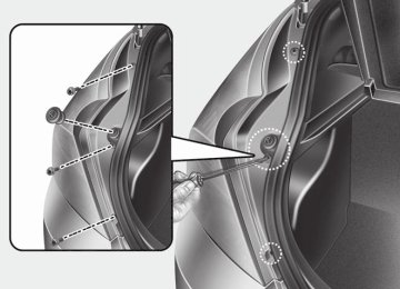
Folding the outside rearview mirror (if equipped) To fold outside rearview mirror, grasp the housing of mirror and then fold it toward the rear of the vehicle.
4 33
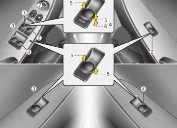
ORBC040023
Electric type (if equipped) The electric remote control mirror switch allows you to adjust the position of the left and right outside rearview mirrors. To adjust the position of either mirror, the ignition switch should be in the ACC or ON position, or engine is running. Push the switch (1) to R or L to select the right side mirror or the left side mirror, then press a corresponding point on the mirror adjustment control to position the select- ed mirror up, down, left or right. After the adjustment, put the switch into the neutral (center) position to prevent inadvertent adjustment.
Features of your vehicle
INSTRUMENT CLUSTER
■ Type A
■ Type B
34
1. Tachometer 2. Turn signal indicators 3. Speedometer 4. Engine temperature gauge 5. Warning and indicator lights 6. Fuel gauge 7. Odometer/Trip computer
❈ The actual cluster in the vehicle may differ
from the illustration. For more details refer to the "Gauges" section in the next pages.
ORB040025N/ORB040026N
Features of your vehicle
■ Type A
ORB040332
■ Type B
ORB040031N
Instrument panel illumination When the vehicle’s parking lights or headlights are on, press the upper or lower part of the switch to adjust the brightness of the instrument panel illumi- nation.
ORB040305
Tachometer The tachometer indicates the approxi- mate number of engine revolutions per minute (rpm). Use the tachometer to select the correct shift points and to prevent lugging and/or over-revving the engine.
ORB040030N
Gauges Speedometer The speedometer indicates the speed of the vehicle. The speedometer is calibrated in miles per hour and/or kilometers per hour.
4 35
Features of your vehicle
When the door is open, or if the engine is not started within 1 minute, the tachometer pointer may move slightly in ON position with the engine OFF. This movement is normal and will not affect the accuracy of the tachometer once the engine is running.
CAUTION
Do not operate the engine within the tachometer's RED ZONE. This may cause severe engine dam- age.
36
■ Type A
■ Type B
WARNING
Never remove the radiator cap when the engine is hot. The engine coolant is under pressure and could cause severe burns. Wait until the engine is cool before adding coolant to the reservoir.
ORB040308N
Engine temperature gauge This gauge shows the temperature of the engine coolant when the ignition switch is ON. Do not continue driving with an overheat- ed engine. If your vehicle overheats, refer to “If the engine overheats” in section 6.
CAUTION
If the gauge moves beyond the nor- mal range area toward the “H”posi- tion, it indicates overheating that may damage the engine.
WARNING - Fuel gauge
Running out of fuel can expose vehicle occupants to danger. You must stop and obtain addition- al fuel as soon as possible after the warning light comes on or when the gauge indicator comes close to the E level.
CAUTION
Avoid driving with a extremely low fuel level.Running out of fuel could cause the engine to misfire,damag- ing the catalytic converter.
■ Type A
■ Type B
ORB040034N
Fuel gauge The fuel gauge indicates the approxi- mate amount of fuel remaining in the fuel tank. The fuel tank capacity is given in section 8. The fuel gauge is supplement- ed by a low fuel warning light, which will illuminate when the fuel tank is near empty. On inclines or curves, the fuel gauge may fluctuate or the low fuel warning light may come on earlier than usual due to the movement of fuel in the tank.
Features of your vehicle
ORBC040035
Trip computer The trip computer is a microcomputer controlling the driver information system. It displays information related to driving on the LCD screen when the ignition switch is in the ON position. If the battery is disconnected, then all stored driving information (except odometer) is reset.
4 37
Features of your vehicle
TRIP A
TRIP B
Distance to empty
Average fuel consumption
Instant fuel consumption
Average speed
Elapsed time
Outside temperature*
* : if equipped
38
■ Type A
■ Type B
■ Type A
■ Type B
ORB040036N
ORB040037N
Odometer (mi. or km) The odometer indicates the total dis- tance the vehicle has been driven. You will also find the odometer useful to determine when periodic maintenance should be performed.
Tripmeter (mi. or km) TRIP A : Tripmeter A TRIP B : Tripmeter B This mode indicates the distance of indi- vidual trips selected since the last trip- meter reset. The meter's working range is from 0.0 to 9999.9 miles (0.0 to 9999.9 km). Pressing the RESET button for more than 1 second, when the tripmeter (TRIP A or TRIP B) is being displayed, clears the tripmeter to zero (0.0).
■ Type A
■ Type B
■ Type A
■ Type B
■ Type A
■ Type B
Features of your vehicle
ORB040038N
ORB040039N
ORB040040N
Distance to empty (mi. or km) This mode indicates the estimated dis- tance to empty based on the current fuel in the fuel tank and the amount of fuel delivered to the engine. When the remaining distance is below 30 miles (50
km), “---” will be displayed and the dis- tance to empty indicator will blink. The meter’s working range is from 30 to 999 miles (50 to 999 km).Average fuel consumption (if equipped) (MPG or l/100 km) This mode calculates the average fuel consumption from the total fuel used and the distance since the last average econ- omy reset. The total fuel used is calculat- ed from the fuel consumption input. For an accurate calculation, drive more than 0.03 miles (50 m). Pressing the RESET button for more than 1 second, when the average fuel econo- my is being displayed, clears the average fuel consumption to zero (----). If the vehicle speed exceeds 1.6 MPH (1km/h) after being refueling, the average fuel economy will be cleared to zero (----).
Instant fuel consumption (l/100 km or MPG) This mode calculates the instant fuel consumption every 2 seconds from the driving distance and quantity of fuel injection.
4 39
Features of your vehicle
■ Type A
■ Type B
■ Type A
■ Type B
■ Type A
■ Type B
ORB040041N
ORB040042N
ORB040309N
Average speed (MPH or km/h) This mode calculates the average speed of the vehicle since the last average speed reset. Even if the vehicle is not in motion, the average speed keeps changing while the engine is running. Pressing the RESET button for more than 1 second, when the average speed is being displayed, clears the average speed to zero (---).
Elapsed time This mode indicates the total time trav- eled since the last driving time reset. Even if the vehicle is not in motion, the driving time keeps increasing while the engine is running. The meter’s working range is from 00:00~99:59. Pressing the RESET button for more than 1 second, when the driving time is being displayed, clears the driving time to zero (00:00).
Outside thermometer (if equipped) The current outside temperature is dis- played in 1°C (1°F) increments. The tem- perature range is between -40°C ~ 60°C (-40°F ~ 140°F). (cid:129) The outside temperature on the display may not change immediately like a general thermometer to prevent the driver from being inattentive.
40
Features of your vehicle
Warnings and indicators All warning lights are checked by turning the ignition switch ON (do not start the engine). Any light that does not illuminate should be checked by an authorized HYUNDAI dealer. After starting the engine, check to make sure that all warning lights are off. If any are still on, this indicates a situation that needs attention. When releasing the parking brake, the brake system warning light should go off. The fuel warning light will stay on if the fuel level is low.
ECO indicator
Air bag warning light
ECO
Active ECO system When the active ECO is operating the ECO indicator is green. For more detailed information, refer to “Active ECO” in chapter 5.
WARNING
Don't keep watching the indicator while driving. It will distract you while driving and cause an accident that results in severe personal injury.
This warning light will illuminate for approximately 6 seconds each time you turn the ignition switch to the ON posi- tion. This light also comes on when the Supplemental Restraint System (SRS) is not working properly. If the SRS air bag warning light does not come on, or continuously remains on after operating for about 6 seconds when you turned the ignition switch to the ON position or start- ed the engine, or if it comes on while driving, have the SRS inspected by an authorized HYUNDAI dealer.
4 41
Features of your vehicle
Anti-lock brake system (ABS) warning light
This light illuminates if the ignition switch is turned ON and goes off in approxi- mately 3 seconds if the system is operat- ing normally. If the ABS warning light remains on, comes on while driving, or does not come on when the ignition switch is turned to the ON position, this indicates that there may be a malfunction with the ABS. If this occurs, have your vehicle checked by an authorized HYUNDAI dealer as soon as possible. The normal braking system will still be operational, but with- out the assistance of the anti-lock brake system.
If the ABS warning light turns on while driving 1.Park the vehicle in a safe place and
turn off the engine.
2.Turn on the engine again. 3.If the warning light illuminates and turns off in approximately 3 seconds, the system is operating normally.
If the warning light does not turn off, have your vehicle checked by an authorized HYUNDAI dealer as soon as possible.
Electronic brake force distri- bution (EBD) system warning light
If these two warning lights illuminate at the same time while driving, your vehicle may have a malfunction with the ABS and EBD system. In this case, your ABS and regular brake system may not work normally. Have the vehicle checked by an authorized HYUNDAI dealer as soon as possible.
WARNING
If the both ABS and brake warning lights are on and stay on, your vehi- cle’s brake system will not work normally during sudden braking. In this case, avoid high speed driving and abrupt braking. Have your vehi- cle checked by an authorized HYUNDAI dealer as soon as possi- ble.
42
✽✽ NOTICE If the ABS warning light or EBD warn- ing light is on and stays on, the speedometer or odometer/tripmeter may not work. In this case, have your vehicle checked by an authorized HYUNDAI dealer as soon as possible.
Seat belt warning
The driver's seat belt warning light and chime will activate to the following table when the ignition switch is in "ON" posi- tion.
Conditions
Warning Pattern
Seat Belt
Vehicle Speed
Light-Blink
Chime- Sound
Unbuckled Buckled
6 seconds
6 seconds
None
Below 3 mph
(5 km/h)
3 mph~ 6 mph
Buckled → Unbuckled
6 seconds
None
6 seconds
Above 6 mph
6 sec. on / 24 sec. off
(10 km/h)
(11 times)
Above 6 mph
(10 km/h)
Unbuckled
↓
Below 3 mph
(5 km/h)
6 seconds *1
↓
Stop *2
*1 Warning pattern repeats 11 times with interval 24 seconds. If the driver's seat belt is buckled, the light will stop within 6 seconds and chime will stop immedi- ately.
*2 The light will stop within 6 seconds and
chime will stop immediately.
Features of your vehicle
Turn signal indicator
The blinking arrows on the instrument panel show the direction indicated by the turn signals. If the arrow comes on but does not blink, blinks more rapidly than normal, or does not illuminate at all, a malfunction in the turn signal system is indicated. Your dealer should be consult- ed for repairs.
High beam indicator
This indicator illuminates when the head- lights are on and in the high beam posi- tion or when the turn signal lever is pulled into the Flash-to-Pass position.
Tail light indicator
This indicator illuminates when the tail lights are on.
4 43
Features of your vehicle
Engine oil pressure warning light
This warning light indicates the engine oil pressure is low. If the warning light illuminates while driv- ing: 1. Drive safely to the side of the road and
stop.
2. With the engine off, check the engine oil level. If the level is low, add oil as required.
If the warning light remains on after adding oil or if oil is not available, call an authorized HYUNDAI dealer.
CAUTION
If the engine is not stopped imme- diately after the engine oil pressure warning light is illuminated,severe damage could result.
44
CAUTION
If the oil pressure warning light stays on while the engine is run- ning, serious engine damage may result. The oil pressure warning light comes on whenever there is insufficient oil pressure. In normal operation,it should come on when the ignition switch is turned on, then go out when the engine is started.If the oil pressure warning light stays on while the engine is running,there is a serious malfunc- tion. If this happens, stop the car as soon as it is safe to do so,turn off the engine and check the oil level.If the oil level is low,fill the engine oil to the proper level and start the engine again. If the light stays on with the engine running, turn the engine off immediately. In any instance where the oil light stays on when the engine is running, the engine should be checked by an authorized HYUNDAI dealer before the car is driven again.
Parking brake & brake fluid warning light
Parking brake warning This light is illuminated when the parking brake is applied with the ignition switch in the START or ON position. The warning light should go off when the parking brake is released.
Low brake fluid level warning If the warning light remains on, it may indicate that the brake fluid level in the reservoir is low. If the warning light remains on: 1. Drive carefully to the nearest safe
location and stop your vehicle.
2. With the engine stopped, check the brake fluid level immediately and add fluid as required. Then check all brake components for fluid leaks.
3. Do not drive the vehicle if leaks are found, the warning light remains on or the brakes do not operate properly. Have the vehicle towed to any author- ized HYUNDAI dealer for a brake sys- tem inspection and necessary repairs.
Your vehicle is equipped with a dual- diagonal braking system. This means you still have braking on two wheels even if one of the brake circuits is damaged or malfunctions. With only one of the circuits working, more than normal pedal travel and greater pedal pressure are required to stop the car. Also, the car will not stop in as short a distance with only a portion of the brake system working. If the brakes fail while you are driving, shift to a lower gear for additional engine braking and stop the car as soon as it is safe to do so. To check bulb operation, check whether the parking brake and brake fluid warning light illuminates when the ignition switch is in the ON position.
WARNING
Driving the vehicle with a warning light on is dangerous. If the brake warning light remains on, have the brakes checked and repaired imme- diately by an authorized HYUNDAI dealer.
Low tire pressure telltale
The low tire pressure telltale illuminates when one or more of your tires is signifi- cantly underinflated. Inflate your tires to the correct inflation pressure. The low tire pressure telltale will illumi- nate after it blinks for approximately one minute when there is a problem with the Tire Pressure Monitoring System. If this occurs, have the system checked by an authorized HYUNDAI dealer as soon as possible. For details, refer to the TPMS on chapter 6.
WARNING - Low tire pres-
sure
low
Significantly tire pressure makes the vehicle unstable and can contribute to loss of vehicle control and increased braking distances. Continued driving on tires with low pressure will cause the tires to overheat and fail.
Features of your vehicle
WARNING - Safe stopping (cid:129) The TPMS cannot alert you to severe and sudden tire damage caused by external factors.
(cid:129) If you feel any vehicle instability, immediately take your foot off the accelerator, apply the brakes gradually and with light force, and slowly move to a safe posi- tion off the road.
4 45
Features of your vehicle
Automatic Transaxleshift indicator
Charging system warning light
Front fog light indicator (if equipped)
The indicator displays which automatic transaxle shift position is selected.
Manual transaxle shift indicator (if equipped)
This indicator informs you which gear is desired while driving to save fuel. For example
: Indicates that shifting up to the 3rd gear is desired (currently the shift lever is in the 2nd gear).
: Indicates that shifting down to the 3rd gear is desired (currently the shift lever is in the 4th gear).
This warning light indicates a malfunction of either the generator or electrical charging system. If the warning light comes on while the vehicle is in motion: 1. Drive to the nearest safe location. 2. With the engine off, check the genera- tor drive belt for looseness or break- age.
3. If the belt is adjusted properly, a prob- lem exists somewhere in the electrical charging system. Have an authorized HYUNDAI dealer correct the problem as soon as possible.
✽✽ NOTICE When the charging system warning light comes on or the voltage is low (when the alteranator (or battery) does not operate normally or it malfunctions), the steer- ing wheel may get heavy and become dif- ficult to control operate abnormally.
This light comes on when the front fog lights are ON.
Trunk lid / tailgate open warning light
This warning light illuminates when the trunk lid / tailgate is not closed securely with the ignition in any position.
Door open warning light
This indicator illuminates when a door is not closed securely.
46
Key reminder warning chime (if equipped) If the driver’s door is opened while the ignition key is left in the ignition switch (ACC or LOCK position), the key reminder warning chime will sound. This helps prevent you from locking your keys in the vehicle. The chime sounds until the key is removed from the ignition switch or the driver’s door is closed.
Low fuel level warning light
This warning light indicates the fuel tank is nearly empty. When it comes on, you should add fuel as soon as possible. Driving with the fuel level warning light on or with the fuel level below “E” can cause the engine to misfire and damage the catalytic converter.
Malfunction indicator light (MIL) (check engine light)
This indicator light is part of the Engine Control System which monitors various emission control system components. If this light illuminates while driving, it indi- cates that a potential malfunction has been detected somewhere in the emis- sion control system. This light will also illuminate when the ignition switch is turned to the ON posi- tion, and will go out in a few seconds after the engine is started. If it illuminates while driving, or does not illuminate when the ignition switch is turned to the ON position, take your vehicle to your near- est authorized HYUNDAI dealer and have the system checked. Generally, your vehicle will continue to be drivable, but have the system checked by an authorized HYUNDAI dealer promptly.
Features of your vehicle
CAUTION
(cid:129) Prolonged driving with the Malfunction Indicator Light illumi- nated may cause damage to the emission control systems which could effect drivability and/or fuel economy.
(cid:129) If the Malfunction Indicator Light illuminates or blinks, potential catalytic converter damage is possible.This could result in loss of engine power.Have the Engine Control System inspected as soon as possible by an author- ized HYUNDAI dealer.
4 47
Features of your vehicle
ESC (Electronic Stability Control) indicator
The ESC indicator will illuminate when the ignition switch is turned ON, but should go off after approximately 3 sec- onds. When the ESC is on, it monitors the driving conditions. Under normal driv- ing conditions, the ESC light will remain off. When a slippery or low traction con- dition is encountered, the ESC will oper- ate, and the ESC indicator will blink to indicate the ESC is operating. The ESC indicator stays on when the ESC may have a malfunction. Take your car to an authorized HYUNDAI dealer and have the system checked.
ESC OFF indicator
Cruise indicator (if equipped)
The ESC OFF indicator will illuminate when the ignition switch is turned ON, but should go off after approximately 3
seconds. To switch to ESC OFF mode, press the ESC OFF button. The ESC OFF indicator will illuminate indicating the ESC is deactivated.CRUISE indicator
CRUISE
The indicator light illuminates when the cruise control system is enabled. The cruise indicator light in the instru- ment cluster is illuminated when the cruise control ON-OFF button on the steering wheel is pushed. The indicator light turns off when the cruise control ON-OFF button is pushed again. For more information about the use of cruise control, refer to “Cruise control system” in section 5.
48
Cruise SET indicator
SET
Electric power steering (EPS) system warning light
EPS
Engine coolant tempera- ture warning light
Features of your vehicle
The indicator light illuminates when the cruise function switch (SET- or RES+) is ON. The cruise SET indicator light in the instrument cluster is illuminated when the cruise control switch (SET- or RES+) is pushed. The cruise SET indicator light does not illuminate when the cruise con- trol switch (CANCEL) is pushed or the system is disengaged.
This indicator light comes on after the ignition key is turned to the ON position and then it will go out. This light also comes on when the EPS needs repairs. If it comes on while driv- ing, have your vehicle inspected by an authorized HYUNDAI dealer. Steering effort may increase significantly if this lamp illuminates. See EPS system in this section.
The warning light illuminates if the tem- perature of the engine coolant is above 257±4.5°F (125±2.5°C). Do not continue driving with an overheat- ed engine. If your vehicle overheats, refer to “Overheating” in section 6.
✽✽ NOTICE If the engine coolant temperature warn- ing light illuminates, it indicates over- heating that may damage the engine.
Fuel cap open warning indicator
This warning light indicates the fuel filler cap is not tight securely. Always make sure that the fuel filler cap is tight.
4 49
Features of your vehicle
HAZARD WARNING FLASHER
ORB040045
The hazard warning flasher should be used whenever you find it necessary to stop the car in a hazardous location. When you must make such an emer- gency stop, always pull off the road as far as possible. The hazard warning lights are turned on by pushing in the hazard switch. This causes all turn signal lights to blink. The hazard warning lights will operate even though the key is not in the ignition switch. To turn the hazard warning lights off, push the switch a second time.50
Features of your vehicle
Headlamp delay (if equipped) If you turn the ignition switch to the ACC or OFF position with the headlights ON, the headlights remain on for about 20
minutes. However, if the driver’s door is opened and closed, the headlights are turned off after 30 seconds. The headlights can be turned off by pressing the lock button on the transmit- ter twice or turning the light switch to the OFF or Auto position. However, if you turn the light switch to the Auto position when it is dark outside, the headlights will not be turned off.Tail lamp warning chime (if equipped) If you turn the ignition switch to the OFF position with the tail lamps ON and the driver's door in an open position, the warning chime will sound. To stop the chime, perform one of the fol- lowing: 1) Turn the ignition key to the ON posi-
tion.
2) Turn the tail lamps OFF. 3) Close the driver's door.
CAUTION
To prevent the battery from being discharged, make sure to turn off the lamp before getting out of the vehicle.
LIGHTING Battery saver function (if equipped) (cid:129) The purpose of this feature is to pre- vent the battery from being dis- charged. The system automatically turns off the parking lights when the driver removes the ignition key and opens the driver-side door.
(cid:129) With this feature, the parking lights will be turned off automatically if the driver parks on the side of road at night. If necessary, to keep the lights on when the ignition key is removed, per- form the following: 1) Open the driver-side door. 2) Turn the parking lights OFF and ON again using the light switch on the steering column.
CAUTION
If the driver gets out of the vehicle through other doors (other than the driver's door), the battery saver function does not operate and the headlamp delay does not turn off automatically. This will cause the battery to be discharged. In this case,make sure to turn off the lamp before getting out of the vehicle.
4 51
Features of your vehicle
ORB040046D
Lighting control The light switch has a Headlight and a Parking light position. To operate the lights, turn the knob at the end of the control lever to one of the fol- lowing positions: (1) OFF position (2) Parking light position (3) Headlight position
ORB040047D
Parking light position ( When the light switch is in the parking light position, the tail, position and license plate lights will turn on and the tail light indicator will turn on.
ORB040048D
Headlight position ( ) When the light switch is in the headlight position the head, tail, license and instru- ment panel lights will turn on.
✽✽ NOTICE The ignition switch must be in the ON position to turn on the headlights.
52
Features of your vehicle
ORB040050D To flash the headlights, pull the lever towards you. It will return to the normal (low beam) position when released. The headlight switch does not need to be on to use this flashing feature.
ORB040051D Turn signals and lane change sig- nals The ignition switch must be on for the turn signals to function. To turn on the turn signals, move the lever up or down (A). Green arrow indicators on the instru- ment panel indicate which turn signal is operating. They will self-cancel after a turn is completed. If the indicator contin- ues to flash after a turn, manually return the lever to the OFF position.
ORB040049D
High beam operation To turn on the high beam headlights, push the lever away from you. Pull it back for low beams. The high beam indicator will light when the headlight high beams are switched on. To prevent the battery from being dis- charged, do not leave the lights on for a prolonged time while the engine is not running.
WARNING
Do not use high beam when there are other vehicles. Using high beam could obstruct the other dri- ver's vision.
4 53
Features of your vehicle
To signal a lane change, move the turn signal lever slightly and hold it in position (B). The lever will return to the OFF posi- tion when released. If an indicator stays on and does not flash or if it flashes abnormally, one of the turn signal bulbs may be burned out and will require replacement.
✽✽ NOTICE If an indicator flash is abnormally quick or slow, a bulb may be burned out or have a poor electrical connection in the circuit.
54
ORB040052D
Front fog light (if equipped) Fog lights are used to provide improved visibility when visibility is poor due to fog, rain or snow etc. The fog lights will turn on when fog light switch (1) is turned to ON after the headlights are turned on. To turn off the fog lights, turn the switch to OFF.
CAUTION
When in operation, the fog lights consume large amounts of vehicle electrical power. Only use the fog lights when visibility is poor or unnecessary battery and generator drain could occur.
WIPERS AND WASHERS ■ Type A
■ Type B
ORBC040054E
OTA040054
D : Rear wiper/washer control
– Wash with brief wipes
(if equipped) · · ON – Continuous wipe · OFF – Off
OTA040053
A : Wiper speed control
· MIST – Single wipe · OFF – Off · INT – Intermittent wipe · LO – Low wiper speed · HI – High wiper speed
B : Intermittent wipe time adjustment C : Wash with brief wipes (front)
Features of your vehicle
Windshield wipers Operates as follows when the ignition switch is turned ON. MIST : For a single wiping cycle, push the lever upward and release it with the lever in the OFF position. The wipers will operate continu- ously if the lever is pushed upward and held.
OFF : Wiper is not in operation INT : Wiper operates intermittently at the same wiping intervals. Use this mode in a light rain or mist. To vary the speed setting, turn the speed control knob.
LO : Normal wiper speed HI
: Fast wiper speed
4 55
Features of your vehicle
■ Type A
✽✽ NOTICE If there is heavy accumulation of snow or ice on the windshield, defrost the windshield for about 10 minutes, or until the snow and/or ice is removed before using the windshield wipers to ensure proper operation.
CAUTION
When starting the vehicle in winter, set the wiper switch in the OFF position. Otherwise, wipers may operate and ice may damage the windshield wiper blades. Always remove all snow and ice and defrost the windshield properly prior to operating the windshield wipers.
■ Type B
ORBC040056E
OTA040056
Windshield washers In the OFF position, pull the lever gently toward you to spray washer fluid on the windshield and to run the wipers 1-3
cycles. Use this function when the windshield is dirty.56
The spray and wiper operation will con- tinue until you release the lever. If the washer does not work, check the washer fluid level. If the fluid level is not sufficient, you will need to add appropri- ate non-abrasive windshield washer fluid to the washer reservoir. The reservoir filler neck is located in the front of the engine compartment on the passenger side.
CAUTION
To prevent possible damage to the washer pump, do not operate the washer when the fluid reservoir is empty.
WARNING
Do not use the washer in freezing temperatures without first warming the windshield with the defrosters; the washer solution could freeze on contact with the windshield and obscure your vision.
CAUTION
(cid:129) To prevent possible damage to the wipers or windshield, do not operate the wipers when the windshield is dry.
(cid:129) To prevent damage to the wiper blades, do not use gasoline, kerosene, paint thinner, or other solvents on or near them.
(cid:129) To prevent damage to the wiper arms and other components, do not attempt to move the wipers manually.
OTA040057
Rear window wiper and washer switch (if equipped) The rear window wiper and washer switch is located at the end of the wiper and washer switch lever. Turn the switch to desired position to operate the rear wiper and washer.
- Spraying washer fluid and wiping
ON - Normal wiper operation OFF - Wiper is not in operation
Features of your vehicle
INTERIOR LIGHT
CAUTION
Do not use the interior lights for extended periods when the engine is not running. It may cause battery discharge.
WARNING
Do not use the interior lights when driving in the dark. Accidents could happen because the view may be obscured by interior lights.
Automatic turn off function (if equipped) The interior lights automatically turn off approximately 20 minutes after the igni- tion switch is turned off.
4 57
Features of your vehicle
ORB040057
Map lamp Push the lens (1) to turn the map lamp on or off. This light produces a spot beam for convenient use as a map lamp at night or as a personal lamp for the driver and the front passenger. (cid:129) DOOR : In the DOOR position, the map lamp and the room lamp come on when any door is opened regardless of ignition switch position.
the
58
When doors are unlocked by the transmitter, the map lamp and the room lamp come on for approximately 30 seconds as long as any door is not open. The map lamp and the room lamp goes out gradually after approximately 30 seconds if the door is closed. However, if the ignition switch is ON or all doors are locked, the map lamp and the room lamp will turn off immediately. If a door is opened with the ignition switch in the ACC or LOCK position, the map lamp and the room lamp stay on for about 20 minutes. However, if a door is opened with the igni- tion switch in the ON position, the map lamp and the room lamp stay on continuously.
(cid:129) ON : Map lamp and room lamp stay on
at all times.
(cid:129) OFF : The lights turn off even if a door
is opened. ❈ When the lamp is turned ON by pressing the lens (1) the lamp does not turn off even if the switch (2) is in the OFF position.
ORB040361
Room lamp (cid:129) ON (1): In the ON position, the light stays on at all times.
(cid:129) DOOR (2) : In the DOOR position, the light comes on when any door is opened regardless of the ignition switch position. When doors are unlocked by the trans- mitter, the light comes on for approxi- mately 30 seconds as long as any door is not open. The light goes out gradually after approximately 30 seconds if the door is closed. However, if the ignition switch is ON or all doors are locked, the light will turn off immediately. If a door is opened with the ignition switch in the ACC or LOCK position, the light stays on for about 20 minutes. However, if a door is opened with the ignition switch in the ON position, the light stays on continuously.
(cid:129) OFF (3) : In the OFF position, the light stays off at all times even when a door is open.
4 Door
5 Door
ORBC040059
ORB041402
Luggage room lamp The luggage room lamp comes on when the trunk lid/tailgate is opened.
Features of your vehicle
CAUTION
The luggage room lamp comes on as long as the trunk lid/tailgate opens. To prevent unnecessary charging system drain, close the trunk lid/tailgate securely after using the luggage room.
4 59
Features of your vehicle
DEFROSTER
CAUTION
To prevent damage to the conduc- tors bonded to the inside surface of the rear window, never use sharp instruments or window cleaners containing abrasives to clean the window.
✽✽ NOTICE If you want to defrost and defog the front windshield, refer to “Windshield defrosting and defogging” in this section. Rear window defroster
ORB040063L
Outside rearview mirror defroster (if equipped) If your vehicle is equipped with the out- side rearview mirror defrosters, they will operate at the same time you turn on the rear window defroster.
indicator on
The defroster heats the window to remove frost, fog and thin ice from the rear window, while the engine is running. To activate the rear window defroster, press the rear window defroster button located in the center facia switch panel. The the rear window defroster button illuminates when the defroster is ON. If there is heavy accumulation of snow on the rear window, brush it off before oper- ating the rear defroster. The rear window defroster automatically turns off after approximately 20 minutes or when the ignition switch is turned off. To turn off the defroster, press the rear window defroster button again.
60
MANUAL CLIMATE CONTROL SYSTEM
Features of your vehicle
1. Temperature control knob 2. Fan speed control knob 3. Air conditioning button 4. Air intake control button 5. Mode selection knob
ORB040065N
4 61
Features of your vehicle
Heating and air conditioning 1. Start the engine. 2. Set the mode to the desired position. For improving the effectiveness of heating and cooling; - Heating: - Cooling:
3. Set the temperature control to the
desired position.
4. Set the air intake control to the outside
(fresh) air position.
5. Set the fan speed control to the
desired speed.
6. If air conditioning is desired, turn the
air conditioning system on.
62
ORB040066
Features of your vehicle
Face-Level (B, D)
Floor-Level (C, A, D, E)
Air flow is directed toward the upper body and face. Additionally, each outlet can be controlled to direct the air discharged from the outlet.
Most of the air flow is directed to the floor, with a small amount of the air being directed to the windshield and side win- dow defrosters.
Bi-Level (B, D, E, C)
Floor/Defrost-Level (A, C, D, E)
Air flow is directed towards the face and the floor.
Most of the air flow is directed to the floor and the windshield with a small amount directed to the side window defrosters.
Defrost-Level (A, D)
Most of the air flow is directed to the windshield with a small amount of air directed to the side window defrosters.
ORB040067
Mode selection The mode selection knob controls the direction of the air flow through the venti- lation system. Air can be directed to the floor, dash- board outlets, or windshield. Five sym- bols are used to represent Five, Face, Bi- Level, Floor, Floor-Defrost and Defrost air position.
4 63
Features of your vehicle
ORB040356
ORB040068
ORB040069
Instrument panel vents The outlet vents can be opened or closed separately using the horizontal thumb- wheel. To close the vent, rotate it left to the maximum position. To open the vent, rotate it right to the desired position. Also, you can adjust the direction of air delivery from these vents using the vent control lever as shown.
Temperature control The temperature control knob allows you to control the temperature of the air flow- ing from the ventilation system. To change the air temperature in the pas- senger compartment, turn the knob to the right position for warm and hot air or left position for cooler air.
MAX A/C-Level (B, D, E) To select the MAX A/C, turn the temper- ature knob to the extreme the left. Air flow is directed toward the upper body and face. In this mode, the air conditioning and the recirculated air position will be selected automatically.
✽✽ NOTICE This setting should be used briefly to help quickly cool the interior. After the interior temperature has cooled suffi- ciently, turn the temperature knob away from the MAX A/C position to a com- fortable setting.
64
Recirculated air position
With the recirculated air position selected, air from the passen- ger compartment will be drawn through the heating system and or cooled according to the function select- ed.
heated
ORB040070
Outside (fresh) air position
Features of your vehicle
✽✽ NOTICE Prolonged operation of the heater in the recirculated air position (without air conditioning selected) may cause fog- ging of the windshield and side windows and the air within the passenger com- partment may become stale. In addition, prolonged use of the air conditioning with the recirculated air position selected will result in excessive- ly dry air in the passenger compart- ment.
Air intake control The air intake control is used to select the outside (fresh) air position or recircu- lated air position. To change the air intake control position, press the control button.
With the outside (fresh) air position selected, air enters the vehicle from out- side and is heated or cooled according to the function select- ed.
4 65
Features of your vehicle
WARNING
(cid:129) Continue using the climate con- trol system in the recirculated air position may allow humidity to increase inside the vehicle which may fog the glass and obscure visibility.
(cid:129) Do not sleep in a vehicle with the air conditioning or heating sys- tem on. It may cause serious harm or death due to a drop in the oxygen level and/or body temper- ature.
(cid:129) Continue using the climate control system in the recirculated air position can cause drowsiness or sleepiness, and loss of vehicle control. Set the air intake control to the outside (fresh) air position as much as possible while driving.
66
ORB040073N
ORB040354N
Fan speed control The ignition switch must be in the ON position for fan operation. The fan speed control knob allows you to control the fan speed of the air flowing from the ventilation system. To change the fan speed, turn the knob to the right for higher speed or left for lower speed. Setting the fan speed control knob to the “0” position turns off the fan.
Air conditioning Press the A/C button to turn the air con- ditioning system on (indicator light will illuminate). Press the button again to turn the air conditioning system off.
System operation Ventilation 1. Set the mode to the 2. Set the air intake control to the outside
position.
(fresh) air position.
3. Set the temperature control to the
desired position.
4. Set the fan speed control to the
desired speed.
Heating 1. Set the mode to the 2. Set the air intake control to the outside
position.
(fresh) air position.
3. Set the temperature control to the
desired position.
4. Set the fan speed control to the
desired speed.
5. If dehumidified heating is desired, turn (if
the air conditioning system equipped) on.
Operation Tips (cid:129) To keep dust or unpleasant fumes from entering the vehicle through the venti- lation system, temporarily set the air intake control to the recirculated air position. Be sure to return the control to the fresh air position when the irrita- tion has passed to keep fresh air in the vehicle. This will help keep the driver alert and comfortable.
(cid:129) Air for the heating/cooling system is drawn in through the grilles just ahead of the windshield. Care should be taken that these are not blocked by leaves, snow, ice or other obstructions. (cid:129) To prevent interior fog on the wind- shield, set the air intake control to the fresh air position and fan speed to the desired position, turn on the air condi- tioning system, and adjust the temper- ature control to desired temperature.
(cid:129) If the windshield fogs up, set the mode
to the
or
position.
Features of your vehicle
Air conditioning All HYUNDAI Air Conditioning Systems are filled with environmentally friendly R-134a refrigerant which does not dam- age the ozone layer. 1. Start the engine. Press the air condi-
tioning button.
2. Set the mode to the 3. Set the air intake control to the outside
position.
air or recirculated air position.
4. Adjust the fan speed control and tem- perature control to maintain maximum comfort.
(cid:129) When maximum cooling is desired, set the temperature control to the extreme left position (the MAX A/C position), then set the fan speed control to the highest speed.
4 67
Features of your vehicle
✽✽ NOTICE • When using the air conditioning sys- tem, monitor the temperature gauge closely while driving up hills or in heavy traffic when outside tempera- tures are high. Air conditioning sys- tem operation may cause engine over- heating. Continue to use the blower fan but turn the air conditioning sys- tem off if the temperature gauge indi- cates engine overheating.
• When opening the windows in humid weather air conditioning may create water droplets inside the vehicle. Since excessive water droplets may cause damage to electrical equipment, air conditioning should only be used with the windows closed.
Air conditioning system operation tips (cid:129) If the vehicle has been parked in direct sunlight during hot weather, open the windows for a short time to let the hot air inside the vehicle escape.
(cid:129) To help reduce moisture inside of the windows on rainy or humid days, decrease the humidity inside the vehi- cle by operating the air conditioning system.
(cid:129) During air conditioning system opera- tion, you may occasionally notice a slight change in engine speed as the air conditioning compressor cycles. This is a normal system operation characteristic.
(cid:129) Use the air conditioning system every month only for a few minutes to ensure maximum system performance.
(cid:129) When using the air conditioning sys- tem, you may notice clear water drip- ping (or even puddling) on the ground under the passenger side of the vehi- cle. This is a normal system operation characteristic.
(cid:129) Operating the air conditioning system in the recirculated air position provides maximum cooling, however, continual operation in this mode may cause the air inside the vehicle to become stale. (cid:129) During cooling operation, you may occasionally notice a misty air flow because of rapid cooling and humid air intake. This is a normal system opera- tion characteristic.
(cid:129) If you operate air conditioner exces- sively, the difference between the tem- perature of the outside air and that of the windshield could cause the outer surface of the windshield to fog up, causing loss of visibility. In this case, set the mode selection knob or button to the position and fan speed con- trol to the lower speed.
68
✽✽ NOTICE • Replace the filter according to the
Maintenance Schedule. If the vehicle is being driven in severe conditions such as dusty or rough roads, more frequent air conditioner filter inspections and changes are required.
• When the air flow rate suddenly decreases, the system should be checked at an authorized HYUNDAI dealer.
Outside air
Recirculated
air
Blower Evaporator core
Climate control air filter
Heater core
OHM048209
Climate control air filter (if equipped) The climate control air filter installed behind the glove box filters the dust or other pollutants that come into the vehi- cle from the outside through the heating and air conditioning system. If dust or other pollutants accumulate in the filter over a period of time, the air flow from the air vents may decrease, resulting in moisture accumulation on the inside of the windshield even when the outside (fresh) air position is selected. If this hap- pens, have the climate control air filter replaced by an authorized HYUNDAI dealer.
Features of your vehicle
Checking the amount of air con- ditioner refrigerant and compres- sor lubricant When the amount of refrigerant is low, the performance of the air conditioning is reduced. Overfilling also has a negative impact on the air conditioning system. Therefore, if abnormal operation is found, have the system inspected by an authorized HYUNDAI dealer.
✽✽ NOTICE It is important that the correct type and amount of oil and refrigerant is used. Otherwise, damage to the compressor and abnormal system operation may occur.
WARNING
The air conditioning system should be serviced by an authorized HYUNDAI dealer. Improper service may cause serious injury to the person performing the service.
4 69
Features of your vehicle
AUTOMATIC CLIMATE CONTROL SYSTEM (IF EQUIPPED)
1. AUTO (automatic control) button 2. OFF button 3. Temperature control knob 4. A/C display
5. Air intake control button 6. Fan speed control knob 7. Air conditioning button 8. Mode selection button 9. Front windshield defrost button.
70
ORB040340N
Features of your vehicle
2. Turn the temperature control knob to
set the desired temperature. If the temperature is set to the lowest setting (LO), the air conditioning sys- tem will operate continuously.
3. To turn the automatic operation off, press any button except the tempera- ture control knob. If you press the mode selection button, air conditioning button, defrost button, air intake con- trol button, or the fan speed knob, the selected function will be controlled manually while other functions operate automatically.
For your convenience and to improve the effectiveness of the climate control, use the AUTO button and set the temperature to 73°F (23°C).
ORB040353
✽✽ NOTICE Never place anything over the sensor located on the instrument panel to ensure better control of the heating and cooling system.
ORB040342
Automatic heating and air condi- tioning The automatic climate control system is controlled by simply setting the desired temperature. The Full Automatic Temperature Control (FATC) system automatically controls the heating and cooling system as follows;1. Push the AUTO button. The modes, fan speeds, air intake and air-condi- tioning will be controlled automatically by temperature setting.
4 71
Features of your vehicle
Manual heating and air condition- ing The heating and cooling system can be controlled manually by pushing buttons other than the AUTO button. In this case, the system works sequentially according to the order of buttons selected. When pressing any button except the AUTO button while using automatic oper- ation, the functions not selected will be controlled automatically. 1. Start the engine. 2. Set the mode to the desired position. For improving the effectiveness of heating and cooling; - Heating: - Cooling:
3. Set the temperature control to the
desired position.
4. Set the air intake control to the outside
(fresh) air position.
5. Set the fan speed control to the
desired speed.
6. If air conditioning is desired, turn the
air conditioning system on.
Press the AUTO button in order to con- vert to full automatic control of the sys- tem.
72
Floor & Defrost
Most of the air flow is directed to the floor and the windshield with a small amount directed to the side window defrosters.
Face-Level
Air flow is directed toward the upper body and face. Additionally, each outlet can be controlled to direct the air discharged from the outlet.
Bi-Level
Air flow is directed towards the face and the floor.
Floor-Level
Most of the air flow is directed to the floor, with a small amount of the air being directed to the windshield and side win- dow defrosters.
ORB040347N
Mode selection The mode selection button controls the direction of the air flow through the venti- lation system. The air flow outlet port is converted as follows:
Refer to the illustration in the “Manual cli- mate control system”.
Features of your vehicle
ORB040355N
ORB040068
ORB040341
Defrost-Level Most of the air flow is directed to the windshield with a small amount of air directed to the side window defrosters.
Instrument panel vents The outlet vents can be opened or closed separately using the horizontal thumb- wheel. To close the vent, rotate it left to the maximum position. To open the vent, rotate it right to the desired position. Also, you can adjust the direction of air delivery from these vents using the vent control lever as shown.
Temperature control The temperature will increase to the maximum by turning the knob to the right extremely. The temperature will decrease to the minimum by turning the knob to the left extremely. When turning the knob, the temperature will increase or decrease by 1°F (0.5°C). When set to the lowest temperature set- ting, the air conditioning will operate con- tinuously.
4 73
✽✽ NOTICE Prolonged operation of the heater in the recirculated air position (without air conditioning selected) may cause fog- ging of the windshield and side windows and the air within the passenger com- partment may become stale. In addition, prolonged use of the air con- ditioning with the recirculated air posi- tion selected will result in excessively dry air in the passenger compartment.
Recirculated air position
With the recirculated air position selected, air from the passenger compart- ment will be drawn through the heating system and heated or cooled according to the function selected.
Outside (fresh) air position ■ Type A
selected,
With the outside (fresh) air position air enters the vehicle from out- side and is heated or cooled according to the function selected.
■ Type B
Features of your vehicle
ORB040345N
Air intake control This is used to select the outside (fresh) air position or recirculated air position. To change the air intake control position, push the control button.
74
Features of your vehicle
WARNING
(cid:129) Continued climate control system operation in the recirculated air position may allow humidity to increase inside the vehicle which may fog the glass and obscure visibility.
(cid:129) Do not sleep in a vehicle with the air conditioning or heating system on. It may cause serious harm or death due to a drop in the oxygen level and/or body temperature.
(cid:129) Continued climate control system operation in the recirculated air position can cause drowsiness or sleepiness, and loss of vehicle control. Set the air intake control to the outside (fresh) air position as much as possible while driving.
ORB040344N
ORB040346N
Fan speed control The fan speed can be set to the desired speed by turning the fan speed control knob. The higher the fan speed is, the more air is delivered. Pressing the OFF button turns off the fan.
Air conditioning Push the A/C button to turn the air condi- tioning system on (indicator light will illu- minate). Push the button again to turn the air con- ditioning system off.
4 75
Features of your vehicle
ORB040343
OFF mode Push the OFF button to turn off the air cli- mate control system. However, you can still operate the mode and air intake but- tons as long as the ignition switch is in the ON position.
76
WINDSHIELD DEFROSTING AND DEFOGGING
Features of your vehicle
WARNING - Windshield
heating or
cooling operation
position Do not use the during in extremely humid weather. The dif- ference between the temperature of the outside air and that of the wind- shield could cause the outer sur- face of the windshield to fog up, causing loss of visibility. In this case, set the mode selection knob or button to the position and fan speed control knob or button to the lower speed.
(cid:129) For maximum defrosting, set the tem- the extreme perature control right/hot position and the fan speed control to the highest speed.
to
(cid:129) If warm air to the floor is desired while defrosting or defogging, set the mode to the floor-defrost position.
(cid:129) Before driving, clear all snow and ice from the windshield, rear window, out- side rear view mirrors, and all side win- dows.
(cid:129) Clear all snow and ice from the hood and air inlet in the cowl grill to improve heater and defroster efficiency and to reduce the probability of fogging up the inside of the windshield.
ORB040075N
Manual climate control system