- 2011 Hyundai Accent Owners Manuals
- Hyundai Accent Owners Manuals
- 2005 Hyundai Accent Owners Manuals
- Hyundai Accent Owners Manuals
- 2003 Hyundai Accent Owners Manuals
- Hyundai Accent Owners Manuals
- 2009 Hyundai Accent Owners Manuals
- Hyundai Accent Owners Manuals
- 2008 Hyundai Accent Owners Manuals
- Hyundai Accent Owners Manuals
- 2004 Hyundai Accent Owners Manuals
- Hyundai Accent Owners Manuals
- 2007 Hyundai Accent Owners Manuals
- Hyundai Accent Owners Manuals
- 2012 Hyundai Accent Owners Manuals
- Hyundai Accent Owners Manuals
- Download PDF Manual
-
Speed Rating Symbol
Maximum Speed
112 mph (180 km/h)
118 mph (190 km/h)
130 mph (210 km/h)
149 mph (240 km/h)
Above 149 mph (240 km/h)
44
WARNING - Tire age
Tires degrade over time, even when they are not being used. Regardless of the remaining tread, it is recommended that tires generally be replaced after six (6) years of normal service. Heat caused by hot climates or frequent high loading condi- tions can accelerate the aging process. Failure to follow this warning can result in sudden tire failure, which could lead to a loss of control and an acci- dent involving serious injury or death.
3.Checking tire life (TIN :Tire
Identification Number)
Any tires that are over 6 years old, based on the manufacturing date, (including the spare tire) should be replaced by new ones. You can find the manufacturing date on the tire sidewall (possibly on the inside of the wheel), displaying the DOT Code. The DOT Code is a series of num- bers on a tire consisting of numbers and English letters. The manufactur- ing date is designated by the last four digits (characters) of the DOT code.
DOT : XXXX XXXX OOOO The front part of the DOT means a plant code number, tire size and tread pattern and the last four num- bers indicate week and year manu- factured. For example: DOT XXXX XXXX 1611 represents that the tire was produced in the 16th week of 2011.
4.Tire ply composition and material The number of layers or plies of rub- ber-coated fabric in the tire. Tire man- ufacturers also must indicate the materials in the tire, which include steel, nylon, polyester, and others.The letter "R" means radial ply construc- tion; the letter "D" means diagonal or bias ply construction; and the letter "B" means belted-bias ply construction.
5.Maximum permissible inflation
pressure
This number is the greatest amount of air pressure that should be put in the tire. Do not exceed the maximum permissible inflation pressure. Refer to the Tire and Loading Information label inflation pressure.
for recommended
6.Maximum load rating This number indicates the maximum load in kilograms and pounds that can be carried by the tire. When replacing the tires on the vehicle, always use a tire that has the same load rating as the factory installed tire.
Maintenance
the
7.Uniform tire quality grading Quality grades can be found where applicable on tire sidewall between tread shoulder and maxi- mum section width. For example: TREAD wear 200 TRACTION AA TEMPERATURE A
Traction - AA, A, B & C The traction grades, from highest to lowest, are AA, A, B and C. Those grades represent the tire’s ability to stop on wet pavement as measured under controlled conditions on speci- fied government test surfaces of asphalt and concrete. A tire marked C may have poor traction performance.
WARNING
The traction grade assigned to this tire is based on straight- ahead braking traction tests, and does not include accelera- tion, cornering, hydroplaning, or peak traction characteristics.
Tread wear The tread wear grade is a compara- tive rating based on the wear rate of the tire when tested under controlled conditions on a specified govern- ment test course. For example, a tire graded 150 would wear one-and-a- half times (1½) as well on the gov- ernment course as a tire graded 100. The relative performance of tires depends upon the actual conditions of their use, however, and may depart significantly from the norm due to variations in driving habits, service practices and differences in road characteristics and climate. These grades are molded on the side-walls of passenger vehicle tires. The tires available as standard or optional equipment on your vehicle may vary with respect to grade.
7 45
Maintenance
Temperature -A, B & C The temperature grades are A (the highest), B and C representing the tire’s resistance to the generation of heat and its ability to dissipate heat when tested under controlled condi- tions on a specified indoor laboratory test wheel. Sustained high temperature can cause the material of the tire to degenerate and reduce tire life, and excessive temperature can lead to sudden tire failure. The grade C cor- responds to a level of performance which all passenger car tires must meet under the Federal Motor Vehicle Safety Standard No. 109. Grades B and A represent higher levels of performance on the labora- tory test wheel than the minimum required by law.
46
WARNING - Tire
temperature
The temperature grade for this tire is established for a tire that is properly inflated and not overloaded. Excessive speed, underinflation, or excessive loading, either separately or in combination, can cause heat build-up and possible sudden tire failure. This can cause loss of vehicle control and serious injury or death.
are,
Tire terminology and definitions Air Pressure: The amount of air inside the tire pressing outward on the tire. Air pressure is expressed in pounds per square inch (psi) or kilo- pascal (kPa). Accessory Weight: This means the combined weight of optional acces- sories. Some examples of optional accessories automatic transaxle, power seats, and air con- ditioning. Aspect Ratio: The relationship of a tire's height to its width. Belt: A rubber coated layer of cords that is located between the plies and the tread. Cords may be made from steel or other reinforcing materials. Bead: The tire bead contains steel wires wrapped by steel cords that hold the tire onto the rim. Bias Ply Tire: A pneumatic tire in which the plies are laid at alternate angles less than 90 degrees to the centerline of the tread.
Cold Tire Pressure: The amount of air pressure in a tire, measured in pounds per square inch (psi) or kilo- pascals (kPa) before a tire has built up heat from driving. Curb Weight: This means the weight of a motor vehicle with standard and optional equipment including the maximum capacity of fuel, oil and coolant, but without passengers and cargo. DOT Markings: A code molded into the sidewall of a tire signifying that the tire is in compliance with the U.S. Department of Transportation motor vehicle safety standards. The DOT code includes the Tire Identification Number (TIN), an alphanumeric des- ignator which can also identify the tire manufacturer, production plant, brand and date of production. GVWR: Gross Vehicle Weight Rating GAWR FRT: Gross Axle Weight Rating for the Front Axle. GAWR RR: Gross Axle Weight Rating for the Rear axle.
Intended Outboard Sidewall: The side of an asymmetrical tire, that must always face outward when mounted on a vehicle. Kilopascal (kPa): The metric unit for air pressure. Load Index: An assigned number ranging from 1 to 279 that corre- sponds to the load carrying capacity of a tire. Maximum Inflation Pressure: The maximum air pressure to which a cold tire may be inflated. The maxi- mum air pressure is molded onto the sidewall. Maximum Load Rating: The load rating for a tire at the maximum per- missible inflation pressure for that tire. Maximum Loaded Vehicle Weight: The sum of curb weight; accessory weight; vehicle capacity weight; and production options weight. Normal Occupant Weight: The number of occupants a vehicle is designed to seat multiplied by 150
pounds (68 kg).Maintenance
Occupant Distribution: Designated seating positions. Outward Facing Sidewall: The side of a asymmetrical tire that has a par- ticular side that faces outward when mounted on a vehicle. The outward facing sidewall bears white lettering or bears manufacturer, brand, and/or model name molding that is higher or deeper than the same moldings on the inner facing sidewall. Passenger (P-Metric) Tire: A tire used on passenger cars and some light duty trucks and multipurpose vehicles. Recommended Inflation Pressure: Vehicle manufacturer's recommend- ed tire inflation pressure and shown on the tire placard. Radial Ply Tire: A pneumatic tire in which the ply cords that extend to the beads are laid at 90 degrees to the centerline of the tread. Rim: A metal support for a tire and upon which the tire beads are seat- ed. Sidewall: The portion of a tire between the tread and the bead.
7 47
Maintenance
Speed Rating: An alphanumeric code assigned to a tire indicating the maximum speed at which a tire can operate. Traction: The friction between the tire and the road surface. The amount of grip provided. Tread: The portion of a tire that comes into contact with the road. Treadwear Indicators: Narrow bands, sometimes called "wear bars," that show across the tread of a tire when only 2/32 inch of tread remains. UTQGS: Uniform Tire Quality Grading Standards, a tire information system that provides consumers with ratings for a tire's traction, tempera- ture and treadwear. Ratings are determined by tire manufacturers using government testing proce- dures. The ratings are molded into the sidewall of the tire. Vehicle Capacity Weight: The num- ber of designated seating positions multiplied by 150 lbs. (68 kg) plus the rated cargo and luggage load.
Vehicle Maximum Load on the Tire: Load on an individual tire due to curb and accessory weight plus maximum occupant and cargo weight. Vehicle Normal Load on the Tire: Load on an individual tire that is determined by distributing to each axle its share of the curb weight, accessory weight, and normal occu- pant weight and dviding by 2. Vehicle Placard: A label permanent- ly attached to a vehicle showing the original equipment tire size and rec- ommended inflation pressure.
All season tires HYUNDAI specifies all season tires on some models to provide good performance for use all year round, including snowy and icy road condi- tions. All season tires are identified by ALL SEASON and/or M+S (Mud and Snow) on the tire sidewall. Snow tires have better snow traction than all season tires and may be more appropriate in some areas.
Summer tires HYUNDAI specifies summer tires on some models to provide superior performance on dry roads. Summer tire performance is substantially reduced in snow and ice. Summer tires do not have the tire traction rat- ing M+S (Mud and Snow) on the tire side wall. if you plan to operate your vehicle in snowy or icy conditions. HYUNDAI recommends the use of snow tires or all season tires on all four wheels.
Snow tires If you equip your car with snow tires, they should be the same size and have the same load capacity as the original tires. Snow tires should be installed on all four wheels; other- wise, poor handling may result. Snow tires should carry 4 psi (28
kPa) more air pressure than the pressure recommended for the stan- dard tires on the tire label on the dri- ver's side of the center pillar, or up to the maximum pressure shown on the tire sidewall, whichever is less.48
Do not drive faster than 75 mph (120
km/h) when your car is equipped with snow tires.Tire chains Tire chains, if necessary, should be installed on the front wheels. Be sure that the chains are installed in accordance with the manufactur- er's instructions. To minimize tire and chain wear, do not continue to use tire chains when they are no longer needed.
CAUTION
Since the sidewalls of radial tires are thinner, they can be damaged by mounting some types of snow chains on them. Therefore,the use of snow tires is recommended instead of snow chains.
WARNING - Snow or ice
(cid:129) When driving on roads cov- ered with snow or ice, drive at less than 20 mph (30 km/h).
(cid:129) Use the SAE “S” class or wire
chains.
(cid:129) If you hear noise caused by chains contacting the body, retighten the chain to avoid contact with the vehicle body. (cid:129) To prevent body damage, retighten the chains after driv- ing 0.3~0.6 miles (0.5~1.0 km). (cid:129) Do not use tire chains on vehicles equipped with alu- minum wheels. In unavoid- able circumstance, use a wire type chain.
(cid:129) Use wire chains less than 0.59
inches (15 mm) to prevent damage to the chain’s con- nection.Maintenance
Radial-ply tires Radial-ply tires provide improved tread life, road hazard resistance and smoother high speed ride. The radi- al-ply tires used on this vehicle are of belted construction, and are selected to complement the ride and handling characteristics of your vehicle. Radial-ply tires have the same load carrying capacity, as bias-ply or bias belted tires of the same size, and use the same recommended inflation pressure. Mixing of radial-ply tires with bias-ply or bias belted tires is not recommended. Any combina- tions of radial-ply and bias-ply or bias belted tires when used on the same vehicle will seriously deteriorate vehicle handling. The best rule to fol- low is: Identical radial-ply tires should always be used as a set of four. Longer wearing tires can be more susceptible to irregular tread wear. It is very important to follow the tire rotation interval shown in this section to achieve the tread life potential of these tires. Cuts and punctures in radial-ply tires are repairable only in the tread area, because of sidewall flexing. Consult your tire dealer for radial-ply tire repairs.
7 49
This vehicle has 2 fuse panels, one locat- ed in the driver’s side panel bolster, the other in the engine compartment. If any of your vehicle’s lights, acces- sories, or controls do not work, check the appropriate circuit fuse. If a fuse has blown, the element inside the fuse will be melted. If the electrical system does not work, first check the driver’s side fuse panel. Always replace a blown fuse with one of the same rating. If the replacement fuse blows, this indi- cates an electrical problem. Avoid using the system involved and immediately consult an authorized HYUNDAI dealer. Three kinds of fuses are used:blade type for lower amperage rating, cartridge type, and multi fuse for higher amperage rat- ings.
WARNING - Fuse replace-
ment
(cid:129) Never replace a fuse with any- thing but another fuse of the same rating.
(cid:129) A higher capacity fuse could cause damage and possibly a fire. (cid:129) Never install a wire or aluminum foil instead of the proper fuse - even as a temporary repair. It may cause extensive wiring damage and a possible fire.
CAUTION
Do not use a screwdriver or any other metal object to remove fuses because it may cause a short circuit and damage the system.
Maintenance
FUSES Blade type
Normal
Blown
Cartridge type
Normal
Blown
Multi fuse
Normal
Blown
ORB072110
A vehicle’s electrical system is protected from electrical overload damage by fuses.50
Driver’s side panel
Maintenance
If the headlights or other electrical com- ponents do not work and the fuses are OK, check the fuse panel in the engine compartment. If a fuse is blown, it must be replaced.
ORB070018
Instrument panel fuse replace- ment 1. Turn the ignition switch and all other
switches off.
2. Open the fuse panel cover.
ORB070019
3. Pull the suspected fuse straight out. Use the removal tool provided in the engine compartment fuse panel.4. Check the removed fuse; replace it if it
is blown.
5. Push in a new fuse of the same rating, and make sure it fits tightly in the clips. If it fits loosely, consult an authorized HYUNDAI dealer. If you do not have a spare, use a fuse of the same rating from a circuit you may not need for operating the vehicle, such as the cigarette lighter fuse.
7 51
✽✽ NOTICE • If the memory fuse is pulled up from the fuse panel, the warning chime, audio, clock and interior lamps, etc., will not operate. Some items must be reset after replacement. Refer to “Battery” in this section.
• Even though the memory fuse is pulled up, the battery can still be dis- charged by operation of the head- lights or other electrical devices.
ORB070021
Engine compartment fuse replacement 1. Turn the ignition switch and all other
switches off.
2. Remove the fuse panel cover by
pressing the tab and pulling up.
Maintenance
ORB070020
Memory fuse Your vehicle is equipped with a memory fuse to prevent battery discharge if your vehicle is parked without being operated for prolonged periods. Use the following procedures before parking the vehicle for prolonged periods. 1. Turn off the engine. 2. Turn off the headlights and tail lights. 3. Open the driver’s side panel cover and
pull up the memory fuse.
52
Maintenance
✽✽ NOTICE • If the multi fuse is blown, consult an
authorized HYUNDAI dealer.
• Before remove the multi fuse, discon-
nect the (-) terminal of battery.
3. Check the removed fuse; replace it if it is blown. To remove or insert the fuse, use the fuse puller in the engine com- partment fuse panel.
4. Push in a new fuse of the same rating, and make sure it fits tightly in the clips. If it fits loosely, consult an authorized HYUNDAI dealer.
CAUTION
After checking the fuse panel in the engine compartment, securely install the fuse panel cover. If not, electrical failures may occur from water contact.
ORB070022
Multi fuse If the multi fuse is blown, it must be removed as follows: 1. Turn off the engine. 2. Disconnect the negative battery cable. 3. Remove the fuse panel in the engine
compartment.
4. Remove the nuts shown in the picture
above.
5. Replace the fuse with a new one of the
same rating.
6. Reinstall in the reverse order of
removal.
7 53
Maintenance
Fuse/relay panel description Inside the fuse/relay panel covers, you can find the fuse/relay label describing fuse/relay name and capacity.
Driver’s side panel
Engine compartment
✽✽ NOTICE Not all fuse panel descriptions in this manual may be applicable to your vehi- cle. It is accurate at the time of printing. When you inspect the fuse panel in your vehicle, refer to the fuse panel label.
ORB070023/ORB070024
54
Maintenance
Instrument panel (Driver’s side fuse panel)
Description
Fuse rating
Protected component
P/OUTLET C/LIGHTER ACC A/BAG IND A/BAG T/SIG IG1 2
WIPER RR SPARE 6
SPARE 1
FOG LP FRT ROOM LP 2STOP LP
CLUSTER
IG1 1
ABS
B/UP LP ECU H/LP LH HAZARD SPARE 2
SUNROOF15A 15A 10A 10A 10A 10A 10A 15A 15A 10A 10A 10A
15A
10A
10A
10A
10A 10A 10A 15A 25A 15A
Cigarette Lighter & Power Outlet (Power Outlet) Cigarette Lighter & Power Outlet (Cigarette Lighter) Audio, Power Outside Mirror Switch Instrument Cluster (Air Bag IND.) SRS Control Module, Telltale, Passenger Occupant Detection Sensor Hazard Switch Not Used Multifunction Switch (Wiper), Rear Wiper Moter Not Used Not Used Front Fog Lamp Relay Auto Cut Relay Stop Lamp Switch, Battery Sensor, Stop Lamp RelayE/R Fuse & Relay Box (HAC Relay), Data Link Connector Instrument Cluster (MICOM, IND.), BCM Stop Lamp Switch, ECO Switch, Driver/Passenger Seat Heater Module Tire Pressure Monitoring Module, ATM Shift Lever Switch ILL. EPS Control Module, Rheostat
ABS Control Module, ESC Control Module, ESC Off Switch E/R Fuse & Relay Box (Multipurpose Check Connector, HAC Relay) Back-Up Lamp Switch ECM, PCM Head Lamp LH Hazard Relay, Hazard Switch Not Used Sunroof Motor
7 55
Maintenance
Description
Fuse rating
Protected component
SPARE 3
TCU IGN COILIG2
WIPER FRT DR LOCK SPARE 4
S/HEATER SPARE 5ROOM LP 1
AUDIO
TAIL LP LH
TAIL LP RH
START H/LP RH P/WDW LH P/WDW RH
HTD MIRR
A/CON BLOWER
56
10A 15A 15A
10A
25A 20A 25A 15A 10A
10A
20A
10A
10A
10A 10A 25A 25A
10A
10A 10A
Not Used Vehicle Speed Sensor, Transaxle Range Switch Ignition Coil #1~#4, Condenser Power Window Relay, A/C Control Module, Instrument Cluster (MICOM) BCM, Sunroof Motor, E/R Fuse & Relay Box (Blower Relay) Multifunction Switch (Wiper), Front Wiper Motor Door Lock/Unlock Relay, Two Turn Unlock Relay Driver Door Lock Actuator Not Used Driver/Passenger Seat Heater Module Not Used Instrument Cluster (IND.,ILL.), Tire Pressure Monitoring Module, BCM A/C Control Module, Luggage Room Lamp, Trunk Room Lamp Center Room Lamp, Overhead Console Lamp, Map Lamp Audio Rear Combination Lamp LH, Head Lamp LH, Front Turn Signal Lamp LH License Lamp LH/RH (4Door), License Lamp (5Door) Head Lamp RH, Rear Combination Lamp RH, Rheostat, Audio Front Turn Signal Lamp RH, Hazard Switch, Instrument Cluster (ILL.+) AUX & USB Jack, ESC Off Switch, A/C Switch, ECO Switch Multifunction Switch (Remote Control), A/C Control Module Rear Defogger Switch, Front Deicer Switch, ATM Shift Lever Switch ILL. Transaxle Range Switch, Ignition Lock Switch Instrument Cluster (High Beam IND.), Head Lamp RH Power Window Main Switch, Rear Power Window Switch LH Power Window Main Switch, Rear Power Window Switch RHPassenger Power Window Switch ECM, PCM, Rear Defogger Switch, Driver Power Outside Mirror Passenger Power Outside Mirror A/C Control Module (Auto A/C) ECM, PCM, Blower Switch, Blower Resistor A/C Control Module (Manual A/C)
Maintenance
Engine compartment main fuse panel
Description MDPS BLOWER RR HTD ABS 2
ABS 1MULTI FUSE
ALT
B+1
IG2
IG1
ECU 1
C/FAN B+2
HORN F/PUMP A/CON INJECTORSENSOR
ECU 2
B/UP LP
WIPER
FUSE
Fuse rating
Protected component
80A 40A 40A 40A 40A
125A
50A
50A 40A 30A 30A 50A 10A 10A 10A 15A
10A
10A
10A
10A
EPS Control Module Blower Relay I/P Junction Box (Rear Defogger Relay) ABS Control Module, ESC Control Module ABS Control Module, ESC Control Module, Multipurpose Check Connector Alternator, E/R Fuse & Relay Box (Multi Fuse : ABS 1, ABS 2, MDPS, RR HTD, BLOWER, Fuse : A/CON) I/P Junction Box (Power Connector Fuse : ROOM LP 1, AUDIO, Fuse : FOG LP FRT, ROOM LP 2, STOP LP, Relay : Tail Lamp) Start Relay, Ignition Switch Ignition Switch Fuse : ECU 2, Engine Control Relay Cooling Fan (High) Relay, Cooling Fan (Low) Relay I/P Junction Box (Fuse : S/HEATER, SUNROOF, DR LOCK, HAZARD, Relay : Power Window) Horn Relay Fuel Pump Relay A/CON Relay ECM, PCM, Oil Control Valve #1/#2, Oxygen Sensor (Up)/(Down), Fuel Pump Relay ECM, PCM, Canister Purge Control Solenoid Valve, Variable Intake Solenoid Valve, Canister Close Valve, Immobilizer Module, A/CON Relay Cooling Fan (High) Relay, Cooling Fan (Low) Relay ECM, PCM PCM, Transaxle Range Switch, Instrument Cluster, Rear Combination Lamp LH/RH, ATM Shift Lever Switch ILL. ECM, PCM, Multifunction Switch (Wiper), Front Wiper Motor
7 57
CAUTION
If you don’t have necessary tools, the correct bulbs and the expertise, consult an authorized HYUNDAI dealer.In many cases,it is difficult to replace vehicle light bulbs because other parts of the vehicle must be removed before you can get to the bulb. This is especially true if you have to remove the head- light assembly to get to the bulb(s). Removing/installing the headlight assembly can result in damage to the vehicle.
✽✽ NOTICE After heavy, driving rain or washing, headlight and taillight lenses could appear frosty. This condition is caused by the temperature difference between the lamp inside and outside. This is similar to the condensation on your windows inside your vehicle during the rain and doesn’t indicate a problem with your vehicle. If the water leaks into the lamp bulb circuitry, have the vehicle checked by an authorized HYUNDAI dealer.
Maintenance
LIGHT BULBS
WARNING - Working on
the lights
Prior to working on the light, firmly apply the parking brake, ensure that the ignition switch is turned to the LOCK position and turn off the lights to avoid sudden movement of the vehicle and burning your fin- gers or receiving an electric shock.
Use only bulbs of the specified wattage.
CAUTION
Be sure to replace the burned-out bulb with one of the same wattage rating. Otherwise, it may cause damage to the fuse or electric wiring system.
58
ORB070025
Headlight, position light, turn sig- nal light, side marker light and front fog light bulb replacement (1) Headlight (High/Low) (2) Front turn signal light / Position light (3) Side marker (4) Front fog light (if equipped)Maintenance
✽✽ NOTICE If the headlight aiming adjustment is necessary after the headlight assembly is reinstalled, consult an authorized HYUNDAI dealer.
ORB071048N
Headlight / Side marker 1. Open the hood. 2. Remove the headlight bulb cover by
turning it counterclockwise.
3. Disconnect the headlight bulb socket-
connector.
4. Unsnap the headlight bulb retaining wire by depressing the end and push- ing it upward.
5. Remove the bulb from the headlight
assembly.
6. Install a new headlight bulb and snap the headlight bulb retaining wire into position by aligning the wire with the groove on the bulb.
7. Connect the headlight bulb socket-
8. Install the headlight bulb cover by turn-
connector.
ing it clockwise.
7 59
(Continued) (cid:129) If a bulb becomes damaged or cracked, replace it immediately and carefully dispose of it.
(cid:129) Wear eye protection when chang- ing a bulb. Allow the bulb to cool down before handling it.
Maintenance
OHD076046
WARNING - Halogen bulbs (cid:129) Halogen bulbs contain pressur- ized gas that will produce flying pieces of glass if broken.
(cid:129) Always handle them carefully, and avoid scratches and abra- sions. If the bulbs are lit, avoid contact with liquids. Never touch the glass with bare hands. Residual oil may cause the bulb to overheat and burst when lit. A bulb should be operated only when installed in a headlight.
(Continued)
60
ORBC070049
Turn signal light/Position light 1. Turn off the engine and open the hood. 2. Remove the socket from the assembly by turning the socket counterclockwise until the tabs on the socket align with the slots on the assembly.
3. Remove the bulb from the socket by pressing it in and rotating it counter- clockwise until the tabs on the bulb align with the slots in the socket. Pull the bulb out of the socket
4. Insert a new bulb by inserting it into the socket and rotating it until it locks into place.
5. Install the socket in the assembly by aligning the tabs on the socket with the slots in the assembly. Push the socket into the assembly and turn the socket clockwise.
4. Remove the bulb-socket from the housing by turning the socket counter clockwise until the tabs on the socket align with the slots on the housing.
5. Install the new bulb-socket into the housing by aligning the tabs on the socket with the slots in the housing. Push the socket into the housing and turn the socket clockwise.
6. Connect the power connector to the
socket.
7. Reinstall the front bumper under cover.
ORBC070030
ORBC070031
Front fog light bulbs (if equipped) 1. Remove the front bumper under cover. 2. Reach your hand into the back of the
front bumper.
3. Disconnect the power connector from
the socket.
Maintenance
ORB070068
Side repeater light bulb replace- ment (if equipped) Type A 1. Remove the light assembly from the vehicle by prying the lens and pulling the assembly out.
2. Disconnect the bulb electrical connec-
tor.
3. Separate the socket and the lens parts by turning the socket counterclockwise until the tabs on the socket align with the slots on the lens part.
7 61
Maintenance
4. Remove the bulb by pulling it straight
out.
5. Insert a new bulb in the socket. 6. Reassemble the socket and the lens
part.
7. Connect the bulb electrical connector. 8. Reinstall the light assembly to the
body of the vehicle.
62
ORB070054
ORBC070033
Type B If the light bulb does not operate, have the vehicle checked by an authorized HYUNDAI dealer.
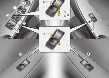
Rear combination light bulb replacement (4 Door) (1) Stop and tail light (2) Rear turn signal light (3) Back-up light (4) Side marker
Maintenance
ORB071033
Rear combination light bulb replacement (5 Door) (1) Tail light (2) Rear turn signal light (3) Back-up light (4) Stop and tail light (5) Side marker
7 63
ORBC070034
1. Open the trunk lid. 2. Remove the service cover by pulling
out the service cover.
ORB071051N 3. Remove the socket from the assembly by turning the socket counterclockwise until the tabs on the socket align with the slots on the assembly.
4. Remove the bulb from the socket by pressing it in and rotating it counter- clockwise until the tabs on the bulb align with the slots in the socket. Pull the bulb out of the socket.
5. Insert a new bulb by inserting it into the socket and rotating it until it locks into place.
6. Install the socket in the assembly by aligning the tabs on the socket with the slots in the assembly. Push the socket into the assembly and turn the socket clockwise.
7. Install the service cover by putting it
into the service hole.
Maintenance
8. Reinstall the light assembly to the
body of the vehicle. 9. Tighten the screws.
ORB071056
ORB071057
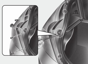
1. Open the tailgate. 2. Loosen the light assembly retaining
screws with a cross-tip screwdriver.
3. Remove the rear combination light assembly from the body of the vehicle.
64
ORB071058N 4. Remove the socket from the assembly by turning the socket counterclockwise until the tabs on the socket align with the slots on the assembly.
5. Remove the bulb from the socket by pressing it in and rotating it counter- clockwise until the tabs on the bulb align with the slots in the socket. Pull the bulb out of the socket.
6. Insert a new bulb by inserting it into the socket and rotating it until it locks into place.
7. Install the socket in the assembly by aligning the tabs on the socket with the slots in the assembly. Push the socket into the assembly and turn the socket clockwise.
Type (LED/Bulb)
Maintenance
ORBC070043
ORBC070041
ORB071043
(cid:2)(cid:2) 5 Door If the light is not operating, have the vehi- cle checked by an authorized HYUNDAI dealer.
ORBC070036
High mounted stop light bulb replacement (if equipped) (cid:2)(cid:2) 4 Door 1. Open the trunk lid. 2. Remove the socket by turning it coun-
terclockwise.
3. Replace the bulb from the socket. 4. Install the socket by turning it clock-
wise.
ORBC070042
License plate light bulb replace- ment (cid:2)(cid:2) 4 Door 1. Remove the trunk trim. 2. Remove the socket by turning it coun-
terclockwise.
3. Remove the bulb by pulling it straight
out.
7 65
Maintenance
4. Install a new bulb. 5. Install the socket by turning it clock-
wise.
6. Install the trunk trim.
Front map lamp
ORB071055
Room lamp
ORB070065
(cid:2)(cid:2) 5 Door 1. Using a flat-blade screwdriver, remove the light assembly from the vehicle by prying the lens gently.
2. Remove the socket from the lens. 3. Remove the bulb by pulling it straight
out.
4. Install a new bulb in the socket and
install the socket to the lens.
5. Reinstall the lens securely.
CAUTION
Use care not to dirty or damage lens,lens tab,and plastic housings.
ORB070064
Interior light bulb replacement 1. Using a flat-blade screwdriver, gently pry the lens from the interior light housing.
2. Remove the bulb by pulling it straight
out.
66
WARNING
Prior to working on the Interior Lights, ensure that the “OFF” but- ton is depressed to avoid burning your fingers or receiving an electric shock.
3. Install a new bulb in the socket. 4. Align the lens tabs with the interior light housing notches and snap the lens into place.
5. If the map lamp and room lamp are not operating, have the vehicle checked by an authorized HYUNDAI dealer.
CAUTION
Use care not to dirty or damage lens,lens tab,and plastic housings.
Maintenance
7 67
Maintenance
APPEARANCE CARE Exterior care Exterior general caution It is very important to follow the label directions when using any chemical cleaner or polish. Read all warning and caution statements that appear on the label.
Finish maintenance Washing To help protect your vehicle’s finish from rust and deterioration, wash it thoroughly and frequently at least once a month with lukewarm or cold water. If you use your vehicle for off-road driv- ing, you should wash it after each off- road trip. Pay special attention to the removal of any accumulation of salt, dirt, mud, and other foreign materials. Make sure the drain holes in the lower edges of the doors and rocker panels are kept clear and clean. Insects, tar, tree sap, bird droppings, industrial pollution and similar deposits can damage your vehicle’s finish if not removed immediately. Even prompt washing with plain water may not completely remove all these deposits. A mild soap, safe for use on painted surfaces, may be used.
68
After washing, rinse the vehicle thor- oughly with lukewarm or cold water. Do not allow soap to dry on the finish.
CAUTION
(cid:129) Do not use strong soap,chemical detergents or hot water, and do not wash the vehicle in direct sunlight or when the body of the vehicle is warm.
(cid:129) Be careful when washing the side
windows of your vehicle. Especially, with high-pressure water,water may leak through the windows and wet the interior.
(cid:129) To prevent damage to the plastic parts and lamps, do not clean with chemical solvents or strong detergents.
WARNING - Wet brakes
After washing the vehicle, test the brakes while driving slowly to see if they have been affected by water. If braking performance is impaired, dry the brakes by applying them lightly while maintaining a slow for- ward speed.
OJB037800
CAUTION
(cid:129) Water washing in the engine com- partment including high pressure water washing may cause the fail- ure of electrical circuits or engine and related components located in the engine compartment.
(cid:129) Never allow water or other liquids to come in contact with electri- cal/electronic components and air duct inside the vehicle as this may damage them.
Waxing Wax the vehicle when water will no longer bead on the paint. Always wash and dry the vehicle before waxing. Use a good quality liquid or paste wax, and follow the manufacturer’s instructions. Wax all metal trim to protect it and to maintain its luster. Removing oil, tar, and similar materials with a spot remover will usually strip the wax from the finish. Be sure to re-wax these areas even if the rest of the vehicle does not yet need waxing.
CAUTION
(cid:129) Wiping dust or dirt off the body with a dry cloth will scratch the finish.
(cid:129) Do not use steel wool, abrasive cleaners, or strong detergents containing highly alkaline or caustic agents on chrome-plated or anodized aluminum parts.This may result in damage to the pro- tective coating and cause discol- oration or paint deterioration.
Finish damage repair Deep scratches or stone chips in the painted surface must be repaired promptly. Exposed metal will quickly rust and may develop into a major repair expense.
✽✽ NOTICE If your vehicle is damaged and requires any metal repair or replacement, be sure the body shop applies anti-corrosion materials to the parts repaired or replaced.
Bright-metal maintenance (cid:129) To remove road tar and insects, use a tar remover, not a scraper or other sharp object.
(cid:129) To protect the surfaces of bright-metal parts from corrosion, apply a coating of wax or chrome preservative and rub to a high luster.
(cid:129) During winter weather or in coastal areas, cover the bright metal parts with a heavier coating of wax or preserva- tive. If necessary, coat the parts with non-corrosive petroleum jelly or other protective compound.
Maintenance
Underbody maintenance Corrosive materials used for ice and snow removal and dust control may col- lect on the underbody. If these materials are not removed, accelerated rusting can occur on underbody parts such as the fuel lines, frame, floor pan and exhaust system, even though they have been treated with rust protection. Thoroughly flush the vehicle underbody and wheel openings with lukewarm or cold water once a month, after off-road driving and at the end of each winter. Pay special attention to these areas because it is difficult to see all the mud and dirt. It will do more harm than good to wet down the road grime without removing it. The lower edges of doors, rocker panels, and frame members have drain holes that should not be allowed to clog with dirt; trapped water in these areas can cause rusting.
7 69
Maintenance
WARNING
After washing the vehicle, test the brakes while driving slowly to see if they have been affected by water. If braking performance is impaired, dry the brakes by applying them lightly while maintaining a slow for- ward speed.
Aluminum wheel maintenance The aluminum wheels are coated with a clear protective finish. (cid:129) Do not use any abrasive cleaner, pol- ishing compound, solvent, or wire brushes on aluminum wheels. They may scratch or damage the finish.
(cid:129) Use only a mild soap or neutral deter- gent, and rinse thoroughly with water. Also, be sure to clean the wheels after driving on salted roads. This helps pre- vent corrosion.
(cid:129) Avoid washing the wheels with high-
speed car wash brushes.
(cid:129) Do not use any cleaners containing acid or acid detergents. It may damage and corrode the aluminum wheels coated with a clear protective finish.
Corrosion protection Protecting your vehicle from corrosion By using the most advanced design and construction practices to combat corro- sion, we produce cars of the highest quality. However, this is only part of the job. To achieve the long-term corrosion resistance your vehicle can deliver, the owner's cooperation and assistance is also required.
Common causes of corrosion The most common causes of corrosion on your car are: (cid:129) Road salt, dirt and moisture that is allowed to accumulate underneath the car.
(cid:129) Removal of paint or protective coatings by stones, gravel, abrasion or minor scrapes and dents which leave unpro- tected metal exposed to corrosion.
70
High-corrosion areas If you live in an area where your car is regularly exposed to corrosive materials, corrosion protection is particularly impor- tant. Some of the common causes of accelerated corrosion are road salts, dust control chemicals, ocean air and industrial pollution.
Maintenance
To help prevent corrosion You can help prevent corrosion from get- ting started by observing the following:
Keep your car clean The best way to prevent corrosion is to keep your car clean and free of corrosive materials. Attention to the underside of the car is particularly important.
(cid:129) If you live in a high-corrosion area — where road salts are used, near the ocean, areas with industrial pollution, acid rain, etc.—, you should take extra care to prevent corrosion. In winter, hose off the underside of your car at least once a month and be sure to clean the underside thoroughly when winter is over.
Moisture breeds corrosion Moisture creates the conditions in which corrosion is most likely to occur. For example, corrosion is accelerated by high humidity, particularly when tempera- tures are just above freezing. In such conditions, the corrosive material is kept in contact with the car surfaces by mois- ture that is slow to evaporate. Mud is particularly corrosive because it is slow to dry and holds moisture in contact with the vehicle. Although the mud appears to be dry, it can still retain the moisture and promote corrosion. High temperatures can also accelerate corrosion of parts that are not properly ventilated so the moisture can be dis- persed. For all these reasons, it is par- ticularly important to keep your car clean and free of mud or accumulations of other materials. This applies not only to the visible surfaces but particularly to the underside of the car.
7 71
Maintenance
(cid:129) When cleaning underneath the car, give particular attention to the compo- nents under the fenders and other areas that are hidden from view. Do a thorough job; just dampening the accu- mulated mud rather than washing it away will accelerate corrosion rather than prevent it. Water under high pres- sure and steam are particularly effec- tive in removing accumulated mud and corrosive materials.
(cid:129) When cleaning lower door panels, rocker panels and frame members, be sure that drain holes are kept open so that moisture can escape and not be trapped inside to accelerate corrosion.
Keep your garage dry Don't park your car in a damp, poorly ventilated garage. This creates a favor- able environment for corrosion. This is particularly true if you wash your car in the garage or drive it into the garage when it is still wet or covered with snow, ice or mud. Even a heated garage can contribute to corrosion unless it is well ventilated so moisture is dispersed.
72
Keep paint and trim in good condition Scratches or chips in the finish should be covered with "touch-up" paint as soon as possible to reduce the possibility of cor- rosion. If bare metal is showing through, the attention of a qualified body and paint shop is recommended.
Bird droppings : Bird droppings are high- ly corrosive and may damage painted surfaces in just a few hours. Always remove bird droppings as soon as possi- ble.
Don't neglect the interior Moisture can collect under the floor mats and carpeting to cause corrosion. Check under the mats periodically to be sure the carpeting is dry. Use particular care if you carry fertilizers, cleaning materials or chemicals in the car. These should be carried only in proper containers and any spills or leaks should be cleaned up, flushed with clean water and thoroughly dried.
Interior care Interior general precautions Prevent caustic solutions such as per- fume and cosmetic oil from contacting the dashboard because they may cause damage or discoloration. If they do con- tact the dashboard, wipe them off imme- diately. See the instructions that follow for the proper way to clean vinyl.
CAUTION
(cid:129) Never allow water or other liquids to come in contact with electri- cal/electronic components inside the vehicle as this may damage them.
(cid:129) When cleaning leather products (steering wheel, seats etc.), use neutral detergents or low alcohol content solutions.If you use high alcohol content solutions or acid/alkaline detergents,the color of the leather may fade or the sur- face may get stripped off.
Cleaning the upholstery and interior trim Vinyl Remove dust and loose dirt from vinyl with a whisk broom or vacuum cleaner. Clean vinyl surfaces with a vinyl cleaner.
Fabric Remove dust and loose dirt from fabric with a whisk broom or vacuum cleaner. Clean with a mild soap solution recom- mended for upholstery or carpets. Remove fresh spots immediately with a fabric spot cleaner. If fresh spots do not receive immediate attention, the fabric can be stained and its color can be affected. Also, its fire-resistant properties can be reduced if the material is not properly maintained.
CAUTION
Using anything but recommended cleaners and procedures may affect the fabric’s appearance and fire- resistant properties.
Cleaning the lap/shoulder belt web- bing Clean the belt webbing with any mild soap solution recommended for cleaning upholstery or carpet. Follow the instruc- tions provided with the soap. Do not bleach or re-dye the webbing because this may weaken it.
Cleaning the interior window glass If the interior glass surfaces of the vehi- cle become fogged (that is, covered with an oily, greasy or waxy film), they should be cleaned with glass cleaner. Follow the directions on the glass cleaner container.
CAUTION
Do not scrape or scratch the inside of the rear window.This may result in damage to the rear window defroster grid.
Maintenance
7 73
Maintenance
EMISSION CONTROL SYSTEM The emission control system of your vehicle is covered by a written limited warranty. Please see the warranty infor- mation contained the Owner’s Handbook & Warranty Information book- let in your vehicle. Your vehicle is equipped with an emis- sion control system to meet all applicable emission regulations. There are three emission control sys- tems, as follows.
in
(1) Crankcase emission control system (2) Evaporative emission control system (3) Exhaust emission control system
In order to assure the proper function of the emission control systems, it is rec- ommended that you have your car inspected and maintained by an author- ized HYUNDAI dealer in accordance with the maintenance schedule in this manu- al.
74
for
the
Caution Inspection and Maintenance Test (With Electronic Stability Control (ESC) system) (cid:129) To prevent the vehicle from misfir- ing during dynamometer testing, turn the Electronic Stability Control (ESC) system off by pressing the ESC switch.
(cid:129) After dynamometer testing is com- pleted, turn the ESC system back on by pressing the ESC switch again.
1. Crankcase emission control
system
The positive crankcase ventilation sys- tem is employed to prevent air pollution caused by blow-by gases being emitted from the crankcase. This system supplies fresh filtered air to the crankcase through the air intake hose. Inside the crankcase, the fresh air mixes with blow-by gases, which then pass through the PCV valve into the induction system.
2. Evaporative emission control
(including ORVR: Onboard Refueling Vapor Recovery) system
The Evaporative Emission Control System is designed to prevent fuel vapors from escaping into the atmos- phere. (The ORVR system is designed to allow the vapors from the fuel tank to be loaded into a canister while refueling at the gas station, preventing the escape of fuel vapors into the atmosphere.)
Maintenance
Canister Fuel vapors generated inside the fuel tank are absorbed and stored in the onboard canister. When the engine is running, the fuel vapors absorbed in the canister are drawn into the surge tank through the purge control solenoid valve.
Purge Control Solenoid Valve (PCSV) The purge control solenoid valve is con- trolled by the Engine Control Module (ECM); when the engine coolant temper- ature is low during idling, the PCSV clos- es so that evaporated fuel is not taken into the engine. After the engine warms- up during ordinary driving, the PCSV opens to introduce evaporated fuel to the engine.
3. Exhaust emission control
system
The Exhaust Emission Control System is a highly effective system which controls exhaust emissions while maintaining good vehicle performance.
Vehicle modifications (cid:129) This vehicle should not be modified. Modification of your vehicle could affect its performance, safety or dura- bility and may even violate governmen- tal safety and emissions regulations. In addition, damage or performance problems resulting from any modification may not be covered under warranty.
(cid:129) If you use unauthorized electronic devices, it may cause the vehicle to operate abnormally, wire damage, bat- tery discharge and fire. For your safety, do not use unauthorized electronic devices.
Engine exhaust gas precautions (carbon monoxide) (cid:129) Carbon monoxide can be present with other exhaust fumes. Therefore, if you smell exhaust fumes of any kind inside your vehicle, have it inspected and repaired immediately. If you ever sus- pect exhaust fumes are coming into your vehicle, drive it only with all the windows fully open. Have your vehicle checked and repaired immediately.
WARNING - Exhaust
Engine exhaust gases contain car- bon monoxide (CO). Though color- less and odorless, it is dangerous and could be lethal if inhaled. Follow the instructions on this page to avoid CO poisoning.
CALIFORNIA PROPOSI- TION 65 WARNING
Engine exhaust and a wide variety of automobile components and parts, including components found in the interior furnishings in a vehi- cle, contain or emit chemicals known to the State of California to cause cancer and birth defects and reproductive harm. In addition, cer- tain fluids contained in vehicles and certain products of component wear contain or emit chemicals known to the State of California to cause cancer and birth defects or other reproductive harm.
7 75
Maintenance
(cid:129) Do not operate the engine in confined or closed areas (such as garages) any more than what is necessary to move the vehicle in or out of the area.
(cid:129) When the vehicle is stopped in an open area for more than a short time with the engine running, adjust the ventilation system (as needed) to draw outside air into the vehicle.
(cid:129) Never sit in a parked or stopped vehi- cle for any extended time with the engine running.
(cid:129) When the engine stalls or fails to start, excessive attempts to restart the engine may cause damage to the emission control system.
76
Operating precautions for catalytic converters (if equipped)
WARNING - Fire
(cid:129) A hot exhaust system can ignite flammable items under your vehi- cle. Do not park, idle, or drive the vehicle over or near flammable objects, such as grass, vegeta- tion, paper, leaves, etc.
(cid:129) The exhaust system and catalytic system are very hot while the engine is running or immediately after the engine is turned off. Keep away from the exhaust system and catalytic, you may get burned. Also, do not remove the heat sink around the exhaust system, do not seal the bottom of the vehicle or do not coat the vehicle for cor- rosion control. It may present a fire risk under certain conditions.
Your vehicle is equipped with a catalytic converter emission control device. Therefore, the following precautions must be observed: (cid:129) Use only UNLEADED FUEL for gaso-
line engines.
(cid:129) Do not operate the vehicle when there are signs of engine malfunction, such as misfire or a noticeable loss of per- formance.
(cid:129) Do not misuse or abuse the engine. Examples of misuse are coasting with the ignition off and descending steep grades in gear with the ignition off.
(cid:129) Do not operate the engine at high idle speed for extended periods (5 minutes or more).
(cid:129) Do not modify or tamper with any part of the engine or emission control sys- tem. All inspections and adjustments must be made by an authorized HYUNDAI dealer.
(cid:129) Avoid driving with a extremely low fuel level. Running out of fuel could cause the engine to misfire, damaging the catalytic converter.
Failure to observe these precautions could result in damage to the catalytic converter vehicle. Additionally, such actions could void your warranties.
your
and
to
CALIFORNIA PERCHLORATE NOTICE Perchlorate Material-special handling may apply, See www.dtsc.ca.gov/haz- ardouswaste/perchlorate.
Notice to California Vehicle Dismantlers: Perchlorate containing materials, such as air bag inflators, seatbelt pretensioners and keyless remote entry batteries, must be disposed of according to Title 22
California Code of Regulations Section 67384.10 (a).Maintenance
7 77
Engine / 8-2
Dimensions / 8-2
Bulb wattage / 8-2
Tires and wheels / 8-3
Capacity/weight / 8-3
Recommended lubricants and capacities / 8-4
Vehicle identification number (VIN) / 8-6
Vehicle certification label / 8-6
Tire specification and pressure label / 8-7
Engine number / 8-7
Refrigerant label / 8-7
Consumer information / 8-8
Reporting safety defects / 8-9
Binding arbitration / 8-9Specifications, Consumer information, Reporting safety defects
Specifications, Consumer information, Reporting safety defeccts
ENGINE
Item Displacement
Bore x Stroke
Firing order No. of cylinders
cu. in
(cc)
in. (mm)
Gasoline 1.6
97.09 (1591)
3.03x3.36 (77x85.44)
1-3-4-2
4, In-lineDIMENSIONS
Item
Overall length Overall width Overall height
Front tread
Rear tread
Wheelbase
P175/70 R14
P195/50 R16
P175/70 R14
P195/50 R164 Door
172 (4370) 66.9 (1700) 57.1 (1450) 59.3 (1507) 58.6 (1489) 59.5 (1511) 58.8 (1493) 101.2 (2570)
in (mm)
5 Door
162 (4115) 66.9 (1700) 57.1 (1450) 59.3 (1507) 58.6 (1489) 59.5 (1511) 58.8 (1493) 101.2 (2570)
BULB WATTAGE
Light Bulb Headlights (Low/High) Front turn signal lights Side marker lamp (Fr/Rr) Side repeater lights* Front fog lights* Stop and tail light*
4 Door 5 Door
4 Door 5 Door
Rear turn signal lights
Back-up lights
High mounted stop light*
License plate lights Map lamps Room lamp Luggage lamp*
* : If equipped
28
55/60
28/8Wattage Bulb type HB2 L/L PY28/8W W5W L/L WY5W GE881
P28/8W PY27W PY27W W16W W16W W5W L/L W5W L/L FESTOON FESTOON27
28/8
27
27
16
16W5W
Specifications, Consumer information, Reporting safety defeccts
TIRES AND WHEELS
Item
Tire size Wheel size
Normal load*1
Front
Rear
Maximum load
Front
Rear
Inflation pressure bar psi ( kPa)
Wheel lug nut torque
lb•ft (kg(cid:129)m, N(cid:129)m)
P175/70 R14
5.5Jx14
P195/50 R16
6.0Jx16
32 (220)
32 (220)
32 (220)
32 (220)
T125/80 D15
3.5Jx15
60 (420)
60 (420)
60 (420)
60 (420)
65~79
(9~11, 88~107)
Full size tire
Compact spare tire*2
(if equipped)*1 Normal load : Up to 3 persons *2 If your vehicle is not equipped with a compact spare tire, your vehicle will be equipped with a Tire Mobility Kit.
CAPACITY/WEIGHT
Item
Gross vehicle weight
lbs. (kg)
Luggage volume
cu ft (l)
4 Door 5 Door 4 Door 5 Door
Gasoline 1.6
3,527 (1600) 3,549 (1610) 13.7 (389) 21.2 (600)8 3
Specifications, Consumer information, Reporting safety defeccts
RECOMMENDED LUBRICANTS AND CAPACITIES To help achieve proper engine and powertrain performance and durability, use only lubricants of the proper quality. The correct lubricants also help promote engine efficiency that results in improved fuel economy.
These lubricants and fluids are recommended for use in your vehicle.
Lubricant
Volume