- 2011 Hyundai Accent Owners Manuals
- Hyundai Accent Owners Manuals
- 2005 Hyundai Accent Owners Manuals
- Hyundai Accent Owners Manuals
- 2003 Hyundai Accent Owners Manuals
- Hyundai Accent Owners Manuals
- 2009 Hyundai Accent Owners Manuals
- Hyundai Accent Owners Manuals
- 2008 Hyundai Accent Owners Manuals
- Hyundai Accent Owners Manuals
- 2004 Hyundai Accent Owners Manuals
- Hyundai Accent Owners Manuals
- 2007 Hyundai Accent Owners Manuals
- Hyundai Accent Owners Manuals
- 2012 Hyundai Accent Owners Manuals
- Hyundai Accent Owners Manuals
- Download PDF Manual
-
Auto up/down window (if equipped) (Driver's window) Depressing or pulling up the power win- dow switch momentarily to the second detent position (6) completely lowers or lifts the window even when the switch is released. To stop the window at the desired position while the window is in operation, pull up or depress and release the switch to the opposite direction of the movement. If the power window is not operated cor- rectly, the automatic power window sys- tem must be reset as follows: 1. Turn the ignition switch to the ON posi-
tion.
2. Close driver’s window and continue pulling up on driver’s power window switch for at least 1 second after the window is completely closed.
Automatic reversal If the upward movement of the window is blocked by an object or part of the body, the window will detect the resistance and will stop upward movement. The window will then lower approximately 11.8 in. (30
cm) to allow the object to be cleared. If the window detect the resistance while the power window switch is pulled up continuously, the window will stop upward movement then lower approxi- mately 1in. (2.5cm). And if the power win- dow switch is pulled up continuously again within 5 seconds after the window is lowered by the automatic window reversal feature, the automatic window reversal will not operate.WARNING
(cid:129) The automatic reverse feature for the driver’s window is only active when the “auto up” feature is used by fully pulling up the switch. The automatic reverse feature will not operate if the win- dow is raised using the halfway position on the power window switch.
(cid:129) Always check for obstructions before raising any window to avoid injuries or vehicle damage. If an object less than 0.16 in. (4
mm) is caught between the window glass and the upper window channel, the automatic reverse window may not detect the resistance and will not stop and reverse direction.in diameter
16
WARNING
(cid:129) Passengers can be injured if their head, hands or other body parts are trapped by a closing window. Always check for obstructions before raising any window.
(cid:129) NEVER leave the ignition key in
the vehicle.
(cid:129) NEVER leave any child unattend- ed in the vehicle. Even very young children may inadvertently cause the vehicle to move, entan- gle themselves in the windows, or otherwise injure themselves or others.
(cid:129) Do not attempt to operate the main switch on the driver's door and a switch on another door in opposing directions at the same time. If this is done, the window will stop and cannot be opened or closed.
Features of your vehicle
OHD046010
B050A01E
Power window lock button (cid:129) The driver can disable the power win- dow switches on a passenger door by depressing the power window lock switch located on the driver’s door to LOCK (pressed).
(cid:129) When the power window lock switch is ON, the driver’s master control cannot operate the passenger door power windows.
Manual windows (if equipped) To raise or lower the window, turn the window regulator handle clockwise or counterclockwise.
WARNING
When opening or closing the win- dows, make sure your passenger's arms, hands and body are safely out of the way.
4 17
Features of your vehicle
HOOD
OHD046011
Opening the hood 1. Pull the release lever to unlatch the hood. The hood should pop open slightly.
OHD046012
2. Go to the front of the vehicle, raise the hood slightly, pull the secondary latch (1) inside of the hood center and lift the hood (2).OHD046013
3.Pull the support rod from the engineroom.
4.Hold the hood open with the support
rod.
WARNING - Hot parts
Grasp the support rod in the area wrapped in rubber. The rubber will help prevent you from being burned by hot metal when the engine is hot.
18
WARNING
(cid:129) Always double check to be sure that the hood is firmly latched before driving away. If it is not latched, the hood could fly open while the vehicle is being driven, causing a total loss of visibility, which might result in an accident. (cid:129) The support rod must be inserted completely into the hole provided in the hood whenever you inspect the engine compartment.This will prevent the hood from falling and possibly injuring you.
(cid:129) Do not move the vehicle with the hood in the raised position, as vision is obstructed and the hood could fall or be damaged.
Closing the hood 1. Before closing the hood, check the fol-
lowing: (cid:129) All filler caps in engine compartment
must be correctly installed.
(cid:129) Gloves, rags or any other com- bustible material must be removed from the engine compartment.
2. Return the support rod to its clip to
prevent it from rattling.
3. Lower the hood until it is about 1 ft. (30
cm) above the closed position and let it drop. Make sure that it locks into place.WARNING
Make sure the hood is properly locked before driving.
Features of your vehicle
WARNING - Hood
(cid:129) Before closing the hood, ensure that all obstructions are removed from the hood opening. Closing the hood with an obstruction present in the hood opening may result in property damage or severe personal injury.
(cid:129) Do not leave gloves, rags or any other combustible material in the engine compartment. Doing so may cause a heat-induced fire.
4 19
Features of your vehicle
FUEL FILLER LID
Closing the fuel filer lid 1. To install the cap, turn it clockwise until it “clicks”. This indicates that the cap is securely tightened.
2. Close the fuel filler lid and push it light- ly and make sure that it is securely closed.
OHD046014
OUN026020
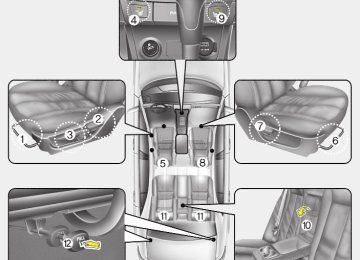
Opening the fuel filer lid The fuel-filler lid must be opened from inside the vehicle by pulling up on the fuel-filler lid opener located on the front floor area on the left side of the car.
✽✽ NOTICE If the fuel-filler lid will not open because ice has formed around it, tap lightly or push on the lid to break the ice and release the lid. Do not pry on the lid. If necessary, spray around the lid with an approved de-icer fluid (do not use radi- ator anti-freeze) or move the vehicle to a warm place and allow the ice to melt.
1. Stop the engine. 2. To open the fuel filler lid, pull the fuel
filler lid opener up.
WARNING
To avoid injury from sharp edges, it is recommended that protective gloves be worn if there is a need to open the fuel filler door manually.
3. Pull the fuel filler lid out to open. 4. To remove the cap, turn the fuel tank
cap counterclockwise.
5. Refuel as needed.
20
WARNING - Refueling
(cid:129) If pressurized fuel sprays out, it can cover your clothes or skin and thus subject you to the risk of fire and burns. Always remove the fuel cap carefully and slowly. If the cap is venting fuel or if you hear a hissing sound, wait until the condition stops before com- pletely removing the cap.
(cid:129) Do not "top off" after the nozzle automatically shuts off when refueling.
(cid:129) Tighten the cap until it clicks, oth- " light will illumi-
erwise the " nate.
(cid:129) Always check that the fuel cap is installed securely to prevent fuel spillage in the event of an acci- dent.
WARNING - Refueling dan-
gers
Automotive fuels are flammable materials. When refueling, please note the following guidelines care- fully. Failure to follow these guide- lines may result in severe personal injury, severe burns or death by fire or explosion. (cid:129) Before refueling note the location of the Emergency Gasoline Shut- Off, if available, at the gas station facility.
(cid:129) Before touching the fuel nozzle, you should eliminate potentially dangerous static electricity dis- charge by touching another metal part of the vehicle, a safe dis- tance away from the fuel filler neck, nozzle, or other gas source. (Continued)
Features of your vehicle
(Continued) (cid:129) Do not get back into a vehicle once you have begun refueling since you can generate static electricity by touching, rubbing or sliding against any item or fab- ric (polyester, satin, nylon, etc.) capable of producing static elec- tricity. Static electricity discharge can ignite fuel vapors resulting in rapid burning. If you must re- enter the vehicle, you should once again eliminate potentially dangerous static electricity dis- charge by touching a metal part of the vehicle, away from the fuel filler neck, nozzle or other gaso- line source.
(cid:129) When using
an
the container on
approved portable fuel container be sure to place the ground prior to refueling. Static electricity discharge from the container can ignite fuel vapors causing a fire. Once refueling has begun, contact with the vehi- cle should be maintained until the filling is complete.
(Continued)
4 21
Features of your vehicle
(Continued)
Use only approved portable plas- tic fuel containers designed to carry and store gasoline.
(cid:129) Do not use cellular phones while refueling. Electric current and/or electronic interference from cel- lular phones can potentially ignite fuel vapors causing a fire. (cid:129) When refueling, always shut the engine off. Sparks produced by electrical components related to the engine can ignite fuel vapors causing a fire. Once refueling is complete, check to make sure the filler cap and filler door are securely closed, before starting the engine.
(cid:129) DO NOT use matches or a lighter and DO NOT SMOKE or leave a lit cigarette in your vehicle while at a gas station especially during refueling. Automotive fuel is highly flammable and can, when ignited, result in fire.
(Continued)
22
(Continued) (cid:129) Do not spill fuel on the exterior surfaces of the vehicle.Any type of fuel spilled on painted surfaces may damage the paint.
(cid:129) If the fuel filler lid will not open in cold weather because the area around it is frozen,push or lightly tap the lid.
(cid:129) After refueling,make sure the fuel cap is installed securely to pre- vent fuel spillage in the event of an accident.
(Continued) (cid:129) If a fire breaks out during refuel- ing, leave the vicinity of the vehi- cle, and immediately contact the manager of the gas station and then contact the local fire depart- ment or 911. Follow any safety instructions they provide.
CAUTION
(cid:129) Make sure to refuel with unleaded
fuel only.
(cid:129) If the fuel filler cap requires replacement, use only a genuine Hyundai cap or the equivalent specified for your vehicle. An incorrect fuel filler cap can result in a serious malfunction of the fuel system or emission control system.
(Continued)
Features of your vehicle
✽✽ NOTICE The sunroof cannot slide when it is in the tilt position nor can it be tilted while in an open or slide position.
WARNING
Never adjust the sunshade while driving. This could result in loss of control and an accident that may cause death, serious injury, or property damage.
✽✽ NOTICE In cold and wet climates, sunroof may not work properly due to freezing con- ditions. ✽✽ NOTICE After washing the car or after there is rain, be sure to wipe off any water that is on the sunroof before operating it.
CAUTION
Do not continue to press the sun- roof control button(s) after the sun- roof is in the fully open,closed,or tilt position(s).Damage to the motor or system components could occur.
SUNROOF (IF EQUIPPED)
OHD046016
If your vehicle is equipped with this fea- ture, you can slide or tilt your sunroof with the sunroof control buttons located on the overhead console. 1. Slide button 2. Tilt button 3. Close buttonThe sunroof can only be opened, closed, or tilted when the ignition switch is in the ON position.
4 23
Features of your vehicle
OHD046017
OUN026027
OHD046018
Sliding the sunroof To open the sunroof (autoslide feature), press the slide button (1) on the over- head console (for more than 0.5 sec- onds). The sunroof will slide all the way open. To stop the sunroof sliding at any point, press any sunroof control button. To close the sunroof (autoslide feature), press the close button (3) on the over- head console (for more than 0.5 sec- onds). The sunroof will slide all the way close. To stop the sunroof sliding at any point, press any sunroof control button.
24
Automatic reversal If an object or part of the body is detect- ed while the sunroof is closing automati- cally, it will reverse direction, and then stop. Auto reverse function does not work if a tiny obstacle is blocked between the slid- ing glass and the sunroof sash. You should always check that all passengers and objects are away from the sunroof before closing it.
Tilting the sunroof To open the sunroof (autotilt feature), press the tilt button (2) on the overhead console (for more than 0.5 seconds). The sunroof will tilt all the way open. To stop the sunroof tilting at any point, press any sunroof control button. To close the sunroof, press the close but- ton (3) on the overhead console and hold it until the sunroof is closed.
WARNING
Be careful that someone’s head, hands and body are not trapped by a closing sunroof.
WARNING - Sunroof
(cid:129) Do not extend face, neck, arms or body outside through the sunroof opening while driving.
(cid:129) Make sure hand and face are safely out of the way before clos- ing a sunroof.
Features of your vehicle
CAUTION
(cid:129) Do not press any sunroof control button longer than necessary. Damage to the motor or system components could occur.
(cid:129) Periodically remove any dirt that may accumulate on the guide rail. (cid:129) If you try to open the sunroof when the temperature is below freezing or when the sunroof is covered with snow or ice, the glass or the motor could be dam- aged.
(cid:129) The sunroof is made to slide together with sunshade. Do not leave the sunshade closed while the sunroof is open.
OUN026031
Sunshade The sunshade will be opened with the glass panel automatically when the glass panel is slid. You will have to close it manually if you want it closed.
4 25
Features of your vehicle
OHD046083
In case of an emergency If the sunroof does not open electrically: 1. Open the sunglass holder.
OHD046019
OUN026030
2. Remove the two (2) screws, and thenremove the overhead console.
3. Insert the emergency handle (provided with the vehicle) and turn the handle clockwise to open or counterclockwise to close.
26
Resetting the sunroof Whenever the vehicle battery is discon- nected or discharged, or you use the emergency handle to operate the sun- roof, you have to reset your sunroof sys- tem as follows:
1. Turn the ignition key to the ON posi-
tion.
2. According to the position of the sun-
roof, do as follows. 1) in case that the sunroof has closed
completely or been tilted : Press the tilt button until the sun- roof has tilted upward completely. 2) in case that the sunroof has slide-
opened: Press and hold the close button (for more than 5 seconds) until the sunroof has closed completely. Press the tilt button until the sun- roof has tilted upward completely.
3. Release the tilt button. 4. Press and hold the tilt button (for more than 10 seconds) until the sun- roof has returned to the original posi- tion of tilt after it is raised a little high- er than the maximum tilt position. Then, release the button.
5. Press and hold the tilt button (for more than 5 seconds) until the sun- roof is operated as follows;
TILT DOWN → SLIDE OPEN → SLIDE CLOSE
Then, release the button.
When this is complete, the sunroof sys- tem is reset.
Features of your vehicle
4 27
Features of your vehicle
STEERING WHEEL Electronic power steering Power steering uses the motor to assist you in steering the vehicle. If the engine is off or if the power steering system becomes inoperative, the vehicle may still be steered, but it will require increased steering effort. The motor driven power steering is con- trolled by power steering control unit which sense the steering wheel torque, steering wheel position and vehicle speed to command the motor. The steering wheel becomes heavier as the vehicle’s speed increases and becomes lighter as the vehicle’s speed decreases for the better control of the steering wheel. Should you notice any change in the effort required to steer during normal vehicle operation, have the power steer- ing checked by an authorized Hyundai dealer.
✽✽ NOTICE The following symptoms may occur dur- ing normal vehicle operation: • The EPS warning light does not illumi- nate. • The steering wheel becomes heavier after turning the ignition switch on. This happens as the system performs the EPS system diagnostics. When the diagnostics is completed, the steering wheel will return to its normal condi- tion. • Click noise may be heard from the EPS relay after the ignition switch is turned to the ON or LOCK position. • Motor noise may be heard when the vehicle is at a stop or at a low driving speed. • The steering effort can suddenly increase, if the operation of EPS sys- tem is stopped to prevent serious acci- dents when the malfunction of EPS system is detected by self-diagnosis.
Tilt steering A tilt steering wheel allows you to adjust the steering wheel before you drive. You can also raise it to the highest level to give your legs more room when you exit and enter the vehicle.
The steering wheel should be positioned so that it is comfortable for you to drive, while permitting you to see the instru- ment panel warning lights and gauges.
28
WARNING
(cid:129) Never adjust the angle and height of steering wheel while driving. You may lose your steering con- trol and cause severe personal injury or accidents.
(cid:129) After adjusting, push the steering wheel both up and down to be certain it is locked in position.
Features of your vehicle
OHD046021
To change the steering wheel angle, pull down the lock release lever (1), adjust the steering wheel to the desired angle (2) and height (3), then pull up the lock- release lever to lock the steering wheel in place. Be sure to adjust the steering wheel to the desired position before driv- ing.OHD046022
Horn To sound the horn, press the horn sym- bol on your steering wheel. Check the horn regularly to be sure it operates properly.
CAUTION
(cid:129) To sound the horn,press the area indicated by the horn symbol on your steering wheel (see illustra- tion).The horn will operate only when this area is pressed.
(cid:129) Do not strike the horn severely to operate it,or hit it with your fist. Do not press on the horn with a sharp-pointed object.
4 29
Features of your vehicle
MIRRORS Inside rearview mirror Day/night rearview mirror Adjust the rearview mirror to center on the view through the rear window. Make this adjustment before you start driving.
WARNING - Rear visibility Do not place objects in the rear seat or cargo area which would interfere with your vision out the rear window.
30
OHD046023
Make this adjustment before you start driving and while the day/night lever is in the day position. Pull the day/night lever toward you to reduce glare from the headlights of vehi- cles behind you during night driving. Remember that you lose some rearview clarity in the night position.Electric chromic mirror (ECM) (if equipped) The electric rearview mirror automatical- ly controls the glare from the headlights of the car behind you in nighttime or low light driving conditions. The sensor mounted in the mirror senses the light level around the vehicle, and through a chemical reaction, automatically controls the headlight glare from vehicles behind you. When the engine is running, the glare is automatically controlled by the sensor mounted in the rearview mirror. Whenever the shift lever is shifted into reverse (R), the mirror will automatically go to the brightest setting in order to improve the drivers view behind the vehi- cle.
CAUTION
When cleaning the mirror, use a paper towel or similar material dampened with glass cleaner. Do not spray glass cleaner directly on the mirror as that may cause the liq- uid cleaner to enter the mirror hous- ing.
Features of your vehicle
Indicator light
Glare detection sensor
OHD046024
To operate the electric rearview mirror (cid:129) Press the ON/OFF button (1) to turn the automatic dimming function on. The mirror indicator light will illuminate. Press the ON/OFF button to turn the automatic- dimming function off. The mirror indicator light will turn off.
(cid:129) The mirror defaults to the ON position whenever the ignition switch is turned on.
OHD046025N Electric chromic mirror with homelink system (if equipped) To operate the electric rearview mirror Press the I button (1) to turn the auto- matic- dimming function on. The mirror indicator light will illuminate. Press the O button (2) to turn the auto- matic- dimming function off. The mirror indicator light will turn off.
Homelink buttons
OHD046305N
HomeLink® Wireless Control System Your new mirror comes with an integrat- ed HomeLink Universal Transceiver, which allows you to program the mirror to activate your garage door(s), estate gate, home lighting, etc. The mirror actually learns the codes from your various exist- ing transmitters.
4 31
Retain the original transmitter for future programming procedures (i.e., new vehi- cle purchase). It is also suggested that upon the sale of the vehicle, the pro- grammed HomeLink buttons be erased for security purposes (follow step 1 in the “Programming” portion of this text).
Flashing
Programming Your vehicle may require the ignition switch to be turned to the ACC position for programming and/or operation of HomeLink. It is also recommended that a new battery be replaced in the hand-held transmitter of the device being pro- grammed to HomeLink for quicker train- ing and accurate transmission of the radio-frequency. Follow HomeLink mirror:
these steps
train your
to
OHD046306N 1. When programming the buttons for the first time, press and hold the left and ) simultane- center buttons ( ously until the indicator light begins to flash after approximately 20 seconds. (This procedure erases the factory-set default codes. Do not perform this step to program additional hand-held trans- mitters.)
Features of your vehicle
WARNING
(cid:129) When
programming
the HomeLink® Wireless Control System, you may be operating a garage door or gate operator. Make sure that people and objects are out of the way of the moving door or gate to prevent potential harm or damage.
(cid:129) Do not use HomeLink with any garage door opener that lacks the safety stop and reverse feature as required by federal safety standards. (This includes any garage door opener model manu- factured before April 1, 1982.) A garage door opener which cannot detect an object, signaling the door to stop and reverse, does not meet current federal safety standards. Using a garage door opener without these features increases risk of serious injury or death. For more information, call 1-800-355-3515 or on the internet at www.homelink.com.
32
✽✽ NOTICE For non rolling code garage door open- ers, follow steps 2 - 3. For rolling code garage door openers, follow steps 2 - 6. For Canadian Programming, please fol- low the Canadian Programming section. For help with determining whether your garage is non-rolling code or rolling code, please refer to the garage door openers owner’s manual or contact HomeLink customer service at 1-800- 355-3515.
Flashing
1-3inches
Transmitter
OHD046307N 2. Press and hold the button on the HomeLink system you wish to train and the button on the transmitter while the transmitter is approximately 1 to 3
inches away from the mirror. Do not release the buttons until step 3 has been completed.3. The HomeLink indicator light will flash, first slowly and then rapidly. When the indicator light flashes rapidly, both but- tons may be released. (The rapid flash- ing light indicates successful program- ming of the new frequency signal.)
✽✽ NOTICE Some gate operators and garage door openers may require you to replace step #3 with the “cycling” procedure noted in the “Canadian Programming” section of this document.
Features of your vehicle
Rolling code programming To train a garage door opener (or other rolling code equipped devices) with the rolling code feature, follow these instruc- tions after completing the “Programming” portion of this text. (A second person may make the following training proce- dures quicker & easier.) 4. Locate the “learn” or “smart” button on the device’s motor head unit. Exact location and color of the button may vary by product brand. If there is diffi- culty locating the “learn” or “smart” but- ton, reference the device’s owner’s manual or contact HomeLink at 1-800- 355-3515 or on internet at www.homelink.com.
the
5. Press and release the “learn” or “smart” button on the device’s motor head unit. You have 30 seconds to complete step number 6.
the
release
6. Return to the vehicle and firmly press and programmed HomeLink button up to three times. The rolling code equipped device should now recognize the HomeLink signal and activate when the HomeLink button is pressed. The remaining two buttons may now be programmed if this has not previously been the “Programming” portion of this text.
Refer
done.
to
4 33
Features of your vehicle
Operating HomeLink To operate, simply press the pro- grammed HomeLink button. Activation will now occur for the trained product (garage door, security system, entry door lock, estate gate, or home or office light- ing). For convenience, the hand-held transmitter of the device may also be used at any time. The HomeLink Wireless Controls System (once pro- grammed) or the original hand-held transmitter may be used to activate the device (e.g. garage door, entry door lock, etc.). In the event that there are still pro- gramming difficulties, contact HomeLink at 1-800-355-3515 or on the internet at www.homelink.com.
34
Flashing
OHD046306N Erasing programmed HomeLink but- tons To erase the three programmed buttons (individual buttons cannot be erased): (cid:129) Press and hold the left and center buttons simultaneously, until the indi- cator light begins to flash (approxi- mately 20 seconds). Release both but- tons. Do not hold for longer than 30
seconds.HomeLink is now in the train (or learning) mode and can be programmed at any time.
Reprogramming a single HomeLink button To program a device to HomeLink using a HomeLink button previously trained, follow these steps: 1. Press and hold the desired HomeLink button. Do NOT release until step 4
has been completed.2. When the indicator light begins to flash slowly (after 20 seconds), position the hand-held transmitter 1 to 3 inches away from the HomeLink surface.
3. Press and hold the hand-held trans- mitter button (or press and “cycle” - as described in “Canadian Programming” above).
4. The HomeLink indicator light will flash, first slowly and then rapidly. When the indicator light begins to flash rapidly, release both buttons.
The previous device has now been erased and the new device can be acti- vated by pushing the HomeLink button that has just been programmed. This pro- cedure will not affect any other pro- grammed HomeLink buttons.
Gate operator programming & canadi- an programming During programming, your hand-held transmitter may automatically stop trans- mitting. Continue to press and hold the HomeLink button (note steps 2 through 4
in the “Programming” portion of this text) while you press and re-press (“cycle”) your handheld transmitter every two sec- onds until the frequency signal has been learned. The indicator light will flash slowly and then rapidly after several sec- onds upon successful training.CAUTION
If programming a garage door opener or gate, it is advised to unplug the device during the “cycling”process to prevent possi- ble motor burn-up.
Accessories If you would like additional information on the HomeLink Wireless Control System, HomeLink compatible products, or to purchase other accessories such as the HomeLink® Lighting Package, please contact HomeLink at 1-800-355-3515 or on the internet at www.homelink.com.
This device complies with Part 15 of the FCC rules. Operation is subject to the following two conditions: 1. This device may not cause harmful
interference, and
2. This device must accept any interfer- ence received, including interference that may cause undesired operation.
WARNING
not
The HomeLink transmitter has been tested and complies with FCC and DOC/MDC rules. Changes or modifications expressly approved by the party responsible for compliance could void the user’s authority to operate the equipment. IC: 4112104541A Gentex MODEL/FCC ID: NZLSTDHL3
Features of your vehicle
Outside rearview mirror Be sure to adjust mirror angles before driving. Your vehicle is equipped with both left- hand and right-hand outside rearview mirrors. The mirrors can be adjusted remotely with the remote switch. The mir- ror heads can be folded back to prevent damage during an automatic car wash or when passing in a narrow street.
4 35
Features of your vehicle
WARNING - Rearview mir-
rors
(cid:129) The right outside rearview mirror is convex. Objects seen in the mirror are closer they appear.
than
(cid:129) Use your interior rearview mirror or direct observation to deter- mine the actual distance of fol- lowing vehicles when changing lanes.
CAUTION
Do not scrape ice off the mirror face;this may damage the surface of the glass. If ice should restrict movement of the mirror, do not force the mirror for adjustment.To remove ice,use a deicer spray,or a sponge or soft cloth with very warm water.
36
CAUTION
If the mirror is jammed with ice,do not adjust the mirror by force.Use an approved spray de-icer (not radi- ator antifreeze) to release the frozen mechanism or move the vehicle to a warm place and allow the ice to melt.
WARNING
Do not adjust or fold the outside rearview mirrors while the vehicle is moving. This could result in loss of control, and an accident which could cause death, serious injury or property damage.
B510A01E
Remote control Manual type The outside rearview mirrors are equipped with a remote control for your convenience. It is operated by the control lever in the bottom front corner of the window. Before driving away, always check that your mirrors are positioned so you can see behind you, both to the left and right sides, as well as directly behind your vehicle. When using the mirror, always exercise caution when attempting to judge the distance of vehicles behind or along side of you.
CAUTION
(cid:129) The mirrors stop moving when they reach the maximum adjust- ing angles,but the motor contin- ues to operate while the switch is depressed. Do not depress the switch longer than necessary,the motor may be damaged.
(cid:129) Do not attempt to adjust the out- side rearview mirror by hand. Doing so may damage the parts.
Features of your vehicle
B510E01E
Folding the outside rearview mirror To fold outside rearview mirror, grasp the housing of mirror and then fold it toward the rear of the vehicle.
OHD046025
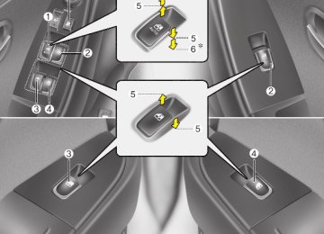
Electric type (if equipped) The electric remote control mirror switch allows you to adjust the position of the left and right outside rearview mirrors. To adjust the position of either mirror, move the lever (1) to R or L to select the right side mirror or the left side mirror, then press a corresponding point ( ) on the mirror adjustment control to position the selected mirror up, down, left or right. After adjustment, put the lever into neu- tral position to prevent the inadvertent adjustment.
4 37
Features of your vehicle
INSTRUMENT CLUSTER
1. Tachometer 2. Turn signal indicators 3. Speedometer 4. Engine temperature gauge 5. Warning and indicator lights 6. Shift position indicator
(Automatic transaxle only)
7. Odometer/Trip computer 8. Fuel gauge
38
OHD046027N
Features of your vehicle
OHD046045L
OHD046028N
OHD046029
Instrument panel illumination When the vehicle’s parking lights or head- lights are on, rotate the illumination con- trol knob to adjust the instrument panel illumination intensity. The instrument cluster illumination inten- sity can be adjusted by rotating the con- trol knob with the headlight switch in any position when the ignition switch is in ON position.
Gauges Speedometer The speedometer indicates the forward speed of the vehicle. The speedometer is calibrated in miles per hour and/or kilometers per hour.
Tachometer The tachometer indicates the approxi- mate number of engine revolutions per minute (rpm). Use the tachometer to select the correct shift points and to prevent lugging and/or over-revving the engine. When the door is open, and if the engine is not started in 1 minute, the tachometer pointer may move slightly in ACC or ON position with the engine OFF. This move- ment is normal and will not affect the accuracy of the tachometer once the engine is running.
CAUTION
Do not operate the engine within the tachometer's RED ZONE. This may cause severe engine damage.
4 39
WARNING
Never remove the radiator cap when the engine is hot. The engine coolant is under pressure and could erupt and cause severe burns. Wait until the engine is cool before adding coolant to the reser- voir.
Features of your vehicle
OHD046031
Engine temperature gauge This gauge shows the temperature of the engine coolant when the ignition switch is ON. Do not continue driving with an overheat- ed engine. If your vehicle overheats, refer to “If the engine overheats” in the Index.
CAUTION
If the gauge pointer moves beyond the normal range area toward the “H”position, it indicates overheat- ing that may damage the engine.
40
OHD046032
Fuel gauge The fuel gauge indicates the approxi- mate amount of fuel remaining in the fuel tank. The fuel tank capacity is given in sec- tion 9. The fuel gauge is supplemented by a low fuel warning light, which will illumi- nate when the fuel tank is nearly empty.
WARNING - Fuel gauge
Running out of fuel can expose vehicle occupants to danger. You must stop and obtain addition- al fuel as soon as possible after the warning light comes on or when the gauge indicator comes close to the E level.
Features of your vehicle
OHD046035
OHD046036N
OHD046033N
Odometer/Tripmeter (if equipped) You can choose the odometer, tripmeter A or tripmeter B by pressing the TRIP button for less than 1 second.
Odometer The odometer indicates the total dis- tance the vehicle has been driven. You will also find the odometer useful to determine when periodic maintenance should be performed.
✽✽ NOTICE It is forbidden that alteration of the odometer of any vehicle with the intent to change the mileage registered on the odometer. The alteration may void your warranty coverage.
Tripmeter TRIP A: Tripmeter A TRIP B: Tripmeter B The tripmeter indicates the distance of individual trips selected by the driver. Tripmeter A or B can be reset to 0 by pressing the TRIP button for 1 second or more, and then releasing.
4 41
Features of your vehicle
OHD046035
Trip computer (if equipped) The trip computer is a microcomputer- controlled driver information system that displays information related to driving, including distance to empty, tripmeter, average fuel consumption and average speed on the display when the ignition switch is in ON position.
Mode selection Push the TRIP button for less than 1 sec- ond to select distance to empty, tripme- ter, average fuel consumption and aver- age speed functions.
42
Distance to empty
Average fuel consumption
Average speed
Tripmeter
OHD046041N
Distance to empty This mode indicates the estimated dis- tance to empty based on the current fuel in the fuel tank and the amount of fuel delivered to the engine. When the remaining distance is below 30 miles (50
km), a “----” symbol will be displayed. The meter’s working range is from 30 to 999 miles (50 to 999 km).✽✽ NOTICE • If the vehicle is not on level ground or the battery power has been interrupt- ed, the “Distance to empty” function may not operate correctly. The trip computer may not register additional fuel if less than 1.6 gallons (6 liters) of fuel are added to the vehi- cle.
• The fuel consumption and distance to empty values may vary significantly based on driving conditions, driving habits, and condition of the vehicle.
• The distance to empty value is an esti- mate of the available driving distance. This value may differ from the actual driving distance available.
Features of your vehicle
Average speed
Odometer
OHD046039N
OHD046040N
Average fuel consumption This mode calculates the average fuel consumption from the total fuel used and the distance since the last average con- sumption reset. The total fuel used is cal- culated from the fuel consumption input. For an accurate calculation, drive more than 0.03 miles (50 m). The meter's working range is from 0.1 to 199.9 miles per gallon (0.1 to 199.9 l/100
km). Press the TRIP button for more than 1
second to reset the average fuel con- sumption to zero (---).Average speed This mode indicates the average speed from the starting of the engine to the igni- tion key "OFF". Average speed is reset to zero if the bat- tery is disconnected. To reset the average speed to zero (---), press the TRIP button for more than 1
second. The meter’s working range is from 0 to 999 MPH.4 43
Features of your vehicle
Tripmeter
Odometer
OHD046043N
Tripmeter This mode indicates the total distance travelled since the last tripmeter reset. Total distance is also reset to zero if the battery is disconnected. Pressing the TRIP button for more than 1
second when the tripmeter is being dis- played clears the tripmeter to zero. The meter's working range is from 0 to 999.9 miles.44
Warnings and indicators All warning lights are checked by turning the ignition switch ON (do not start the engine). Any light that does not illuminate should be checked by an authorized Hyundai dealer. After starting the engine, check to make sure that all warning lights are off. If any are still on, this indicates a situation that needs attention. When releasing the parking brake, the brake system warning light should go off. The fuel warning light will stay on if the fuel level is low.
Air bag warning light (if equipped)
AIR BAG
This warning light will illuminate for approximately 6 seconds each time you turn the ignition switch to the ON posi- tion. This light also comes on when the SRS is not working properly. If the AIR BAG warning light does not come on, or con- tinuously remains on after operating for about 6 seconds when you turned the ignition switch to the ON position or start- ed the engine, or if it comes on while driving, have the SRS inspected by an authorized Hyundai dealer.
Anti-lock brake system (ABS) warning light (if equipped)
This light illuminates if the ignition switch is turned to ON and goes off in approxi- mately 3 seconds if the system is operat- ing normally. If the ABS warning light remains on, comes on while driving, or does not come on when the ignition switch is turned to the ON position, this indicates that there may be a problem with the ABS. If this occurs, have your vehicle checked by an authorized Hyundai dealer as soon as possible. The normal braking system will still be operational, but without the assistance of the anti-lock brake system.
Electronic brake force distri- bution (EBD) system warning light If two warning lights illumi- nate at the same time while driving, your vehicle has a problem with ABS and EBD system. In this case, your ABS and regular brake system may not work normally. Have the vehicle checked by an authorized Hyundai dealer as soon as possible.
WARNING
If the both ABS and Brake warning lights are on and stay on, your vehi- cle’s brake system will not work normally. So you may experience an unexpected and dangerous situ- ation during sudden braking. In this case, avoid high speed driving and abrupt braking. Have your vehicle checked by an authorized Hyundai dealer as soon as possible.
Features of your vehicle
Seat belt warning
Turn signal indicator lights
The blinking green arrows on the instru- ment panel show the direction indicated by the turn signals. If the arrow comes on but does not blink, blinks more rapidly than normal, or does not illuminate at all, a malfunction in the turn signal system is indicated. Your dealer should be consult- ed for repairs.
High beam indicator
This indicator illuminates when the head- lights are on and in the high beam posi- tion or when the turn signal lever is pulled into the Flash-to-Pass position.
Seat belt warning light If the driver's seat belt is not fastened when the ignition key is turned ON, the seat belt warning light blinks for approxi- mately 6 seconds. And if the vehicle speed exceeds 10km/h with the seat belt unfastened, the seat belt warning light blinks with the pattern of 6 seconds on and 24 seconds off for 11 times.The seat belt warning light will stop if the seat belt is fastened or the vehicle speed is reduced to below 5km/h.
Seat belt warning chime If the driver's seat belt is not fastened when the ignition key is turned ON, the seat belt warning chime sounds for approximately 6 seconds. And if the vehi- cle speed exceeds 10 km/h with the seat belt unfastened, the seat belt warning chime sounds with the pattern of 6 sec- onds on and 24 seconds off for 11 times. The seat belt warning chime will stop if the seat belt is fastened or the vehicle speed is reduced to below 5 km/h.
4 45
Features of your vehicle
Engine oil pressure warn- ing
This warning light indicates the engine oil pressure is low. If the warning light illuminates while driv- ing: 1. Drive safely to the side of the road and
stop.
2. With the engine off, check the engine oil level. If the level is low, add oil as required.
If the warning light remains on after adding oil or if oil is not available, call an authorized Hyundai dealer.
CAUTION
If the engine is not stopped imme- diately after the engine oil pressure warning light is illuminated,severe damage could result.
46
CAUTION
If the oil pressure warning light stays on while the engine is run- ning, serious engine damage may result. The oil pressure warning light comes on whenever there is insufficient oil pressure. In normal operation,it should come on when the ignition switch is turned on, then go out when the engine is started.If the oil pressure warning light stays on while the engine is running,there is a serious malfunc- tion. If this happens, stop the car as soon as it is safe to do so,turn off the engine and check the oil level.If the oil level is low,fill the engine oil to the proper level and start the engine again. If the light stays on with the engine running, turn the engine off immediately. In any instance where the oil light stays on when the engine is running, the engine should be checked by an authorized Hyundai dealer before the car is driven again.
Parking brake & brake fluid warning
Parking brake warning This light is illuminated when the parking brake is applied with the ignition switch in the START or ON position. The warning light should go off when the parking brake is released.
Low brake fluid level warning If the warning light remains on, it may indicate that the brake fluid level in the reservoir is low. If the warning light remains on: 1. Drive carefully to the nearest safe
location and stop your vehicle.
2. With the engine stopped, check the brake fluid level immediately and add fluid as required. Then check all brake components for fluid leaks.
3. Do not drive the vehicle if leaks are found, the warning light remains on or the brakes do not operate properly. Have it towed to any authorized Hyundai dealer for a brake system inspection and necessary repairs.
Features of your vehicle
Front fog light indicator (if equipped)
Charging system warning
This light comes on when the front fog lights are ON.
Shift pattern indicators (if equipped)
The individual indicators illu- minate to show the automat- ic transaxle shift lever selec- tion.
This warning light indicates a malfunction of either the generator or electrical charging system. If the warning light comes on while the vehicle is in motion: 1. Drive to the nearest safe location. 2. With the engine off, check the genera- tor drive belt for looseness or break- age.
3. If the belt is adjusted properly, a prob- lem exists somewhere in the electrical charging system. Have an authorized Hyundai dealer correct the problem as soon as possible.
Your vehicle is equipped with dual-diago- nal braking systems. This means you still have braking on two wheels even if one of the dual systems should fail. With only one of the dual systems working, more than normal pedal travel and greater pedal pressure are required to stop the car. Also, the car will not stop in as short a distance with only a portion of the brake system working. If the brakes fail while you are driving, shift to a lower gear for additional engine braking and stop the car as soon as it is safe to do so. To check bulb operation, check whether the parking brake and brake fluid warning light illuminates when the ignition switch is in the ON position.
WARNING
Driving the vehicle with a warning light on is dangerous. If the brake warning light remains on, have the brakes checked and repaired imme- diately by an authorized Hyundai dealer.
4 47
Features of your vehicle
Trunk lid open warning light
Malfunction indicator lamp (MIL) (check engine light)
This warning light illuminates when the trunk lid is not closed securely with the ignition in any position.
Door ajar warning light
This warning light illuminates when a door is not closed securely with the igni- tion in any position.
Low fuel level warning
This warning light indicates the fuel tank is nearly empty. When it comes on, you should add fuel as soon as possible. Driving with the fuel level warning light on or with the fuel level below “E” can cause the engine to misfire and damage the catalytic converter.
This indicator light is part of the Engine Control System which monitors various emission control system components. If this light illuminates while driving, it indi- cates that a potential problem has been detected somewhere in the emission control system. This light will also illuminate when the ignition switch is turned to the ON posi- tion, and will go out in a few seconds after the engine is started. If it illuminates while driving, or does not illuminate when the ignition key is turned to the ON posi- tion, take your vehicle to your nearest authorized Hyundai dealer and have the system checked. Generally, your vehicle will continue to be drivable, but have the system checked by an authorized Hyundai dealer promptly.
CAUTION
(cid:129) Prolonged driving with the Emission Control System Malfunction Indicator Light ) illuminated may cause damage to the emission control systems which could effect dri- vability and/or fuel economy.
(cid:129) If the Emission Control System Malfunction Indicator Light ( illuminates, potential catalytic converter damage is possible which could result in loss of engine power. Have the Engine Control System inspected as soon as possible by an authorized Hyundai dealer.
Low washer fluid level warning indicator
This warning light indicates the washer fluid reservoir is near empty. Refill the washer fluid as soon as possible.
48
ESC (Electronic Stability Control) indicator (if equipped)
ESC
The ESC indicator will illuminate when the ignition switch is turned ON, but should go off after approximately 3 sec- onds. When the ESC is on, it monitors the driving conditions and under normal driving conditions, the ESC light will remain off. When a slippery or low trac- tion condition is encountered, the ESC will operate, and the ESC indicator will blink to indicate the ESC is operating.
ESC OFF indicator (if equipped)
ESC OFF
The ESC OFF indicator will illuminate when the ignition switch is turned ON, but should go off after approximately 3
seconds. To switch to ESC OFF mode, press the ESC OFF button. The ESC OFF indicator will illuminate indicating the ESC is deactivated. If this indicator stays on in the ESC ON mode, the ESC may have a malfunction. Take your car to an authorized Hyundai dealer and have the system checked.Cruise indicator (if equipped)
CRUISE indicator
CRUISE
The indicator light illuminates when the cruise control system is enabled. The cruise indicator light in the instru- ment cluster is illuminated when the cruise control ON/OFF button on the steering wheel is pulled. The indicator light turns off when the cruise control ON/OFF button is pushed again. For more Information about the use of cruise control, refer to section 5, “Cruise control system”.
Cruise SET indicator
SET
The indicator light illuminates when the cruise function switch (COAST/SET or RES/ACCEL) is ON. The cruise SET indicator light in the instrument cluster is illuminated when the cruise control switch (COAST/SET or RES/ACCEL) is pushed. The cruise SET indicator light does not illuminate when the cruise control switch (CANCEL) is pushed or the system is disengaged.
Features of your vehicle
Key reminder warning chime (if equipped) If the driver’s door is opened while the ignition key is left in the ignition switch (ACC or LOCK position), the key reminder warning chime will sound. This is to prevent you from locking your keys in the vehicle. The chime sounds until the key is removed from the ignition switch or the driver’s door is closed.
Electronic power steering (EPS) system warning light
EPS
This indicator light comes on after the ignition key is turned to the ON position and then it will go out with the engine started. This light also comes on when the EPS has some troubles. If it comes on while driving, have your vehicle inspected by an authorized Hyundai dealer.
4 49
Features of your vehicle
HAZARD WARNING FLASHER
OHD046044L The hazard warning flasher should be used whenever you find it necessary to stop the car in a hazardous location. When you must make such an emer- gency stop, always pull off the road as far as possible. The hazard warning lights are turned on by pushing in the hazard switch. This causes all turn signal lights to blink. The hazard warning lights will operate even though the key is not in the ignition. To turn the hazard warning lights off, push the switch a second time.
50
LIGHTING Battery saver function (cid:129) The purpose of this feature is to pre- vent the battery from being dis- charged. The system automatically turns off the small light when the driver removes the ignition key and opens the driver- side door.
(cid:129) With this feature, the parking lights will be turned off automatically if the driver parks on the side of road at night. If necessary, to keep the lights on when the ignition key is removed, per- form the following : 1) Open the driver-side door. 2) Turn the parking lights OFF and ON again using the light switch on the steering column.
Features of your vehicle
OHD046108L
OUN026221
Lighting control The light switch has a Headlight and a Parking light position. To operate the lights, turn the knob at the end of the control lever to one of the fol- lowing positions: (1) OFF position (2) Parking light position (3) Headlight position
Parking light position ( When the light switch is in the parking light position (1st position), the tail, posi- tion, license and instrument panel lights are ON.
4 51
Features of your vehicle
OUN026222
OUN026225
OUN026224
Headlight position ( When the light switch is in the headlight position (2nd position) the head, tail, position, license and instrument panel lights are ON.
✽✽ NOTICE The ignition switch must be in the ON position to turn on the headlights.
High - beam operation To turn on the high beam headlights, push the lever away from you. Pull it back for low beams. The high-beam indicator will light when the headlight high beams are switched on. To prevent the battery from being dis- charged, do not leave the lights on for a prolonged time while the engine is not running.
Flashing headlights To flash the headlights, pull the lever towards you. It will return to the normal (low-beam) position when released. The headlight switch does not need to be on to use this flashing feature.
52
To signal a lane change, move the turn signal lever slightly and hold it in position (B). The lever will return to the OFF posi- tion when released. If an indicator stays on and does not flash or if it flashes abnormally, one of the turn signal bulbs may be burned out and will require replacement.
✽✽ NOTICE If an indicator flash is abnormally quick or slow, bulb may be burned out or have a poor electrical connection in the cir- cuit.
OUN026226
Turn signals and lane change sig- nals The ignition switch must be on for the turn signals to function. To turn on the turn signals, move the lever up or down (A). Green arrow indicators on the instru- ment panel indicate which turn signal is operating. They will self-cancel after a turn is completed. If the indicator contin- ues to flash after a turn, manually return the lever to the OFF position.Features of your vehicle
OUN026219
Front fog light (if equipped) Fog lights are used to provide improved visibility and avoid accidents when visibil- ity is poor due to fog, rain or snow etc. The fog lights will turn on when fog light switch (1) is turned to ON after the head- lights are turned on. To turn off the fog lights, turn the switch to OFF.
CAUTION
When in operation, the fog lights consume large amounts of vehicle electrical power. Only use the fog lights when visibility is poor or unnecessary battery and generator drain could occur.
4 53
INT : Wiper operates intermittently at the same wiping intervals. Use this mode in a light rain or mist. To vary the speed setting, turn the speed control knob(1). (S : slow operation, F: fast operation)
LO : Normal wiper speed HI
: Fast wiper speed
✽✽ NOTICE If there is heavy accumulation of snow or ice on the windshield, defrost the windshield for about 10 minutes, or until the snow and/or ice is removed before using the windshield wipers to ensure proper operation.
CAUTION
(cid:129) To prevent possible damage to the wipers or windshield, do not operate the wipers when the windshield is dry.
(cid:129) To prevent damage to the wiper blades, do not use gasoline, kerosene, paint thinner, or other solvents on or near them.
(cid:129) To prevent damage to the wiper arms and other components, do not attempt to move the wipers manually.
Features of your vehicle
WIPERS AND WASHERS
OHD046046
Windshield wipers Operates as follows when the ignition switch is turned ON.
: For a single wiping cycle, push the lever upward and release it with the lever in the OFF position. The wipers will operate continuously if the lever is pushed upward and held.
OFF : Wiper is not in operation
54
Features of your vehicle
CAUTION
To prevent possible damage to the washer pump, do not operate the washer when the fluid reservoir is empty.
WARNING
Do not use the washer in freezing temperatures without first warming the windshield with the defrosters; the washer solution could freeze on contact with the windshield and obscure your vision.
4 55
OHD046048
Windshield washers In the OFF position, pull the lever gently toward you to spray washer fluid on the windshield and to run the wipers 1-3
cycles. Use this function when the windshield is dirty. The spray and wiper operation will con- tinue until you release the lever. If the washer does not work, check the washer fluid level. If the fluid level is not sufficient, you will need to add appropri- ate non-abrasive windshield washer fluid to the washer reservoir. The reservoir filler neck is located in the front of the engine compartment on the passenger side.Features of your vehicle
INTERIOR LIGHT ✽✽ NOTICE Do not use the interior lights for extend- ed periods when engine is not running. It may cause battery discharge.
56
OHD046049
OHD046050
Map lamp Push in the map lamp lens to turn the light on or off. This light produces a spot beam for convenient use as a map lamp at night or as a personal lamp for the driver and the passenger.
Dome lamp DOOR In the DOOR position, the light comes on when any door is opened regardless of the ignition switch position. The light goes out gradually after 30 seconds if the door is closed. However if the ignition switch is ON or all doors are locked, the light will turn off even within 30 seconds.
Features of your vehicle
ON In the ON position, the light stays on at all times.
CAUTION
Do not leave the switch in this posi- tion for an extended period of time when the vehicle is not running.
OFF In the OFF position, the light stays off at all times even though a door is open.
OHD046104
OHD046051
Trunk room lamp The trunk room lamp comes on when the trunk is opened.
Glove box lamp The glove box lamp comes on when the glove box is opened. The parking lights or headlights must be ON for the glove box lamp to function.
4 57
Features of your vehicle
OHD046052
Vanity mirror lamp (if equipped) Opening the lid of the vanity mirror will automatically turn on the mirror light.
58
DEFROSTER
CAUTION
(cid:129) To prevent damage to the con- ductors bonded to the inside sur- face of the rear window,never use sharp instruments or window cleaners containing abrasives to clean the window.
(cid:129) If you want to defrost and defog on the front windshield, refer to “Windshield Defrosting and Defogging”in this section.
Type A
Type B
OHD046053
OHD046054N
Rear window defroster The defroster heats the window to remove frost, fog and thin ice from the interior and exterior of the rear window, while engine is running.
Features of your vehicle
indicator on
To activate the rear window defroster, press the rear window defroster button located in the center facia switch panel. The the rear window defroster button illuminates when the defroster is ON. If there is heavy accumulation of snow on the rear window, brush it off before oper- ating the rear defroster. The rear window defroster automatically turns off after 20 minutes or when the ignition switch is turned off. To turn off the