- 2011 Hyundai Accent Owners Manuals
- Hyundai Accent Owners Manuals
- 2005 Hyundai Accent Owners Manuals
- Hyundai Accent Owners Manuals
- 2003 Hyundai Accent Owners Manuals
- Hyundai Accent Owners Manuals
- 2009 Hyundai Accent Owners Manuals
- Hyundai Accent Owners Manuals
- 2008 Hyundai Accent Owners Manuals
- Hyundai Accent Owners Manuals
- 2004 Hyundai Accent Owners Manuals
- Hyundai Accent Owners Manuals
- 2007 Hyundai Accent Owners Manuals
- Hyundai Accent Owners Manuals
- 2012 Hyundai Accent Owners Manuals
- Hyundai Accent Owners Manuals
- Download PDF Manual
-
fluid. Serious injury or death could occur.
OHD056005
Checking the parking brake Check the stroke of the parking brake by counting the number of “clicks’’ heard while fully applying it from the released position. Also, the parking brake alone should securely hold the vehicle on a fair- ly steep grade. If the stroke is more or less than specified, have the parking brake adjusted by an authorized Hyundai dealer.
Stroke : 7
“clicks’’
at a
force of
44 lbs (20 kg, 196 N).
OHD076013
Checking the washer fluid level The reservoir is translucent so that you can check the level with a quick visual inspection. Check the fluid level in the washer fluid reservoir and add fluid if necessary. Plain water may be used if washer fluid is not available. However, use washer solvent with antifreeze characteristics in cold cli- mates to prevent freezing.
22
AIR CLEANER
Maintenance
OHD076016
Filter replacement It must be replaced when necessary, and should not be cleaned and reused.
OHD076017
1. Loosen the air cleaner cover attachingclips and open the cover.
OHD076018
2. Replace the air cleaner filter. 3. Lock the cover with the cover attaching
clips.
7 23
Maintenance
Replace the filter according to the Scheduled Maintenance Section. If the vehicle is operated in extremely dusty or sandy areas, replace the ele- ment more often than the usual recom- mended to “Maintenance under severe usage condi- tions”in this section.)
intervals.
(Refer
CAUTION
(cid:129) Do not drive with the air cleaner removed;this will result in exces- sive engine wear.
(cid:129) When removing the air cleaner fil- ter, be careful that dust or dirt does not enter the air intake, or damage may result.
(cid:129) Use a Hyundai genuine part.Use of nongenuine part could damage the air flow sensor.
24
CLIMATE CONTROL AIR FILTER
Maintenance
OHD046065
OHD076020
Filter replacement 1. Open the glove box and remove the
support rod.
Filter inspection The climate control air filter should be replaced every 10,000 miles (15,000
km). If the vehicle is operated in the severely air-polluted cities or on dusty rough roads for a long period, it should be frequently and replaced earlier. When you try to replace the climate control air filter by owner maintenance, replace it performing the following procedure, and be careful to avoid damaging other components.inspected more
OHD076021
2. With the glove box open, remove the stoppers on both sides to allow the glove box hang freely on the hinges.7 25
Maintenance
OHD076022
3. Remove the climate control air filtercase pulling out the cover.
OHD076023
4. Replace the climate control air filter. 5. Reassemble in the reverse order of
disassembly.
✽✽ NOTICE When replacing the climate control air filter install it according to the “AIR FLOW(cid:200)(cid:200)” identification marks. Otherwise, the system may produce noise and the effectiveness of the filter may be reduced.
26
WIPER BLADES
1JBA5122
Blade inspection ✽✽ NOTICE Commercial hot waxes applied by auto- matic car washes have been known to make the windshield difficult to clean.
Maintenance
Contamination of either the windshield or the wiper blades with foreign matter can reduce the effectiveness of the wind- shield wipers. Common sources of con- tamination are insects, tree sap, and hot wax treatments used by some commer- cial car washes. If the blades are not wip- ing properly, clean both the window and the blades with a good cleaner or mild detergent, and rinse thoroughly with clean water.
CAUTION
To prevent damage to the wiper blades, do not use gasoline, kerosene, paint thinner, or other solvents on or near them.
Blade replacement When the wipers no longer clean ade- quately, the blades may be worn or cracked, and require replacement.
CAUTION
To prevent damage to the wiper arms or other components, do not attempt to move the wipers manual- ly.
CAUTION
The use of a non-specified wiper blade could result in wiper malfunc- tion and failure.
7 27
Maintenance
1LDA5023
Front windshield wiper blade 1. Raise the wiper arm and turn the wiper blade assembly to expose the plastic locking clip.
CAUTION
Do not allow the wiper arm to fall against the windshield,since it may chip or crack the windshield.
1JBA7037
1JBA7038
2. Compress the clip and slide the bladeassembly downward.
3. Lift it off the arm. 4. Install the blade assembly in the
reverse order of removal.
28
BATTERY
OHD076024
For best battery service (cid:129) Keep the battery securely mounted. (cid:129) Keep the battery top clean and dry. (cid:129) Keep the terminals and connections clean, tight, and coated with petroleum jelly or terminal grease.
(cid:129) Rinse any spilled electrolyte from the battery immediately with a solution of water and baking soda.
(cid:129) If the vehicle is not going to be used for an extended time, disconnect the bat- tery cables.
Maintenance
(Continued)
If any electrolyte gets into your eyes, flush your eyes with clean water for at least 15 minutes and get immedi- ate medical attention. If electrolyte gets on your skin, thoroughly wash the contacted area. If you feel a pain or a burning sensa- tion, get medical attention immediately. Wear eye protection when charging or working near a battery. Always provide ventilation when working in an enclosed space.
(Continued)
WARNING - Battery dangers
Always read the following instructions carefully when handling a battery. Keep lighted cigarettes and all other flames or sparks away from the battery. Hydrogen, a highly com- bustible gas, is always present in battery cells and may explode if ignited. Keep batteries out of the reach of children because batteries contain highly corrosive SULFURIC ACID. Do not allow battery acid to contact your skin, eyes, clothing or paint finish.
(Continued)
7 29
Reset items Items should be reset after the battery has been discharged or the battery has been disconnected. (cid:129) Sunroof (See Chapter 4) (cid:129) Trip computer (See Chapter 4) (cid:129) Climate control system
(See Chapter 4)
(cid:129) Clock (See Chapter 4) (cid:129) Audio (See Chapter 4) (cid:129) Auto up/down window (See chapter 4)
Maintenance
(Continued) (cid:129) When lifting a plastic-cased bat- tery, excessive pressure on the case may cause battery acid to leak, resulting in personal injury. Lift with a battery carrier or with your hands on opposite corners. (cid:129) Never attempt to recharge the battery when the battery cables are connected.
(cid:129) The electrical ignition system works with high voltage. Never touch these components with the engine running or the ignition switched on.
Failure to follow the above warn- ings can result in serious bodily injury or death.
PROPOSITION 65 WARNING Battery posts, terminals, and relat- ed accessories contain lead and lead compounds, chemicals known to the State of California to cause cancer and reproductive harm. Batteries also contain other chemi- cals known to the State of California to cause cancer. Wash hands after handling.
Battery recharging Your vehicle has a maintenance-free, calcium-based battery. (cid:129) If the battery becomes discharged in a short time (because, for example, the headlights or interior lights were left on while the vehicle was not in use), recharge it by slow charging (trickle) for 10 hours.
(cid:129) If the battery gradually discharges because of high electric load while the vehicle is being used, recharge it at 20- 30A for two hours.
30
Maintenance
(Continued) (cid:129) Disconnect the battery charger in
the following order.
1. Turn off the battery charger main
switch.
2. Unhook the negative clamp from
the negative battery terminal.
3. Unhook the positive clamp from
the positive battery terminal.
WARNING
(cid:129) Before performing maintenance or recharging the battery, turn off all accessories and stop the engine.
(cid:129) The negative battery cable must be removed first and installed last when the battery is discon- nected.
WARNING - Recharging
battery
recharging
the battery, When observe the following precautions: (cid:129) The battery must be removed from the vehicle and placed in an area with good ventilation.
(cid:129) Do not allow cigarettes, sparks,
or flame near the battery.
(cid:129) Watch the battery during charg- ing, and stop or reduce the charg- ing rate if the battery cells begin gassing (boiling) violently or if the temperature of the electrolyte of any cell exceeds 120°F (49°C). (cid:129) Wear eye protection when check-
ing the battery during charging.
(Continued)
7 31
Maintenance
TIRES AND WHEELS Tire care For proper maintenance, safety, and maximum fuel economy, you must always maintain recommended tire inflation pressures and stay within the load limits and weight distribution recommended for your vehicle.
Recommended cold tire inflation pressures All tire pressures (including the spare) should be checked when the tires are cold. “Cold Tires” means the vehicle has not been driven for at least three hours or driven less than one mile (1.6 km). Recommended pressures must be maintained for the best ride, top vehi- cle handling, and minimum tire wear.
WARNING
(cid:129) Underinflated or overinflated tires can cause poor handling, loss of vehicle control, and sudden tire failure leading to accidents, injuries, and even death. Always check tires are properly inflated before driv- ing.
(cid:129) Driving on tires with no or insufficient tread is danger- ous. Worn-out tires can result in loss of vehicle control, col- lisions, and injury and even death. Worn-out tires should be replaced as soon as possi- ble and should never be used for driving. Always check tire tread before driving your car.
32
OHD086003
All specifications (sizes and pres- sures) can be found on a label attached to the vehicle.WARNING - Tire underin-
flation
Severe underinflation (10 psi (70 kPa) or more) can lead to severe heat build-up, causing blowouts, tread separation and other tire failures that can result in the loss of vehicle control leading to severe injury or death. This risk is much higher on hot days and when driving for protracted periods at high speeds.
CAUTION
(cid:129) Underinflation also results in excessive wear,poor handling and reduced fuel economy. Wheel deformation also is possible.Keep your tire pres- sures at the proper levels.If a tire frequently needs refilling, have it checked by an author- ized Hyundai dealer.
(cid:129) Overinflation produces a harsh ride, excessive wear at the center of the tire tread,and a greater possibility of dam- age from road hazards.
CAUTION
(cid:129) Warm tires normally exceed recommended cold tire pres- sures by 4 to 6 psi (28 to 41
kPa). Do not release air from warm tires to adjust the pres- sure or the tires will be under- inflated.(cid:129) Be sure to reinstall the tire inflation valve caps. Without the valve cap,dirt or moisture could get into the valve core and cause air leakage. If a valve cap is missing,install a new one as soon as possible.
WARNING - Tire inflation Overinflation or underinflation can reduce tire life, adversely affect vehicle handling, and lead to sudden tire failure. This could result in loss of vehicle control and potential injury.
Maintenance
CAUTION - Tire pressure Always observe the following: (cid:129) Check tire pressure when the tires are cold. (After vehicle has been parked for at least three hours or hasn't been driven more than one mile (1.6
km) since startup.)(cid:129) Check the pressure of your spare tire each time you check the pressure of other tires.
(cid:129) Never overload your vehicle. Be careful not to overload a vehicle luggage rack if your vehicle is equipped with one. (cid:129) Worn,old tires can cause acci- dents. If your tread is badly worn, or if your tires have been damaged,replace them.
7 33
Maintenance
Checking tire inflation pressure Check your tires once a month or more. Also, check the tire pressure of the spare tire.
How to check Use a good quality gage to check tire pressure. You can not tell if your tires are properly inflated simply by look- ing at them. Radial tires may look properly inflated even when they're underinflated. Check the tire's inflation pressure when the tires are cold. - "Cold" means your vehicle has been sitting for at least three hours or driven no more than 1 mile (1.6 km).
Remove the valve cap from the tire valve stem. Press the tire gage firm- ly onto the valve to get a pressure measurement. If the cold tire inflation pressure matches the recommended pressure on the tire and loading information label, no further adjust- ment is necessary. If the pressure is low, add air until you reach the rec- ommended amount. If you overfill the tire, release air by pushing on the metal stem in the center of the tire valve. Recheck the tire pressure with the tire gage. Be sure to put the valve caps back on the valve stems. They help prevent leaks by keeping out dirt and mois- ture.
34
WARNING
(cid:129) Inspect your tires frequently for proper inflation as well as wear and damage. Always use a tire pressure gauge.
(cid:129) Tires with too much or too lit- tle pressure wear unevenly causing poor handling, loss of vehicle control, and sudden tire failure leading to acci- dents, injuries, and even death. The recommended cold tire pressure for your vehicle can be found in this manual and on the tire label located on the driver's side of the cen- ter pillar.
(cid:129) Worn tires can cause acci- dents. Replace tires that are worn, show uneven wear, or are damaged.
(cid:129) Remember to check the pres- tire. sure of your spare Hyundai recommends that you check the spare every time you check the pressure of the other tires on your vehi- cle.
Tire rotation To equalize tread wear, it is recom- mended that the tires be rotated every 7,500 miles (12,000 km) or sooner if irregular wear develops. During rotation, check the tires for correct balance. When rotating tires, check for uneven wear and damage. Abnormal wear is usually caused by incorrect tire pres- sure, improper wheel alignment, out- of-balance wheels, severe braking or severe cornering. Look for bumps or bulges in the tread or side of tire. Replace the tire if you find either of these conditions. Replace the tire if fabric or cord is visible. After rotation, be sure to bring the front and rear tire pressures to specification and check lug nut tightness. Refer to Section 9, “Specifications”.
With a full-size spare tire (if equipped)
Without a spare tire
S2BLA790
Maintenance
Disc brake pads should be inspected for wear whenever tires are rotated.
✽✽ NOTICE Rotate radial tires that have an asymmetric tread pattern only from front to rear and not from right to left.
WARNING
(cid:129) Do not use the compact spare
tire for tire rotation.
Directional tires (if equipped)
S2BLA790A
(cid:129) Do not mix bias ply and radial ply tires under any circum- stances. This may cause unusual handling characteris- tics that could result in death, severe injury, or property damage.
CBGQ0707A
7 35
Maintenance
Wheel alignment and tire balance The wheels on your vehicle were aligned and balanced carefully at the factory to give you the longest tire life and best overall performance. In most cases, you will not need to have your wheels aligned again. However, if you notice unusual tire wear or your vehicle pulling one way or the other, the alignment may need to be reset. If you notice your vehicle vibrating when driving on a smooth road, your wheels may need to be rebalanced.
CAUTION
Improper wheel weights can damage your vehicle's alu- minum wheels. Use only approved wheel weights.
36
Tread wear indicator
1LDA5026
Tire replacement If the tire is worn evenly, a tread wear indicator will appear as a solid band across the tread. This shows there is less than 1/16 inch (1.6 mm) of tread left on the tire. Replace the tire when this happens. Do not wait for the band to appear across the entire tread before replac- ing the tire.
WARNING - Replacing
tires
To reduce the chance or serious or fatal injuries from an accident caused by tire failure or loss of vehicle control: (cid:129) Replace tires that are worn, show uneven wear, or are damaged. Worn tires can cause loss of braking effec- tiveness, steering control, and traction.
(cid:129) Do not drive your vehicle with too little or too much pressure in your tires. This can lead to uneven wear and tire failure.
(cid:129) When replacing tires, never mix radial and bias-ply tires on the same car. You must replace all tires (including the spare) if moving from radial to bias-ply tires.
(Continued)
(Continued) (cid:129) Using tires and wheel other than the recommended sizes could cause unusual handling characteristics and poor vehi- cle control, resulting in a seri- ous accident.
(cid:129) Wheels that do not meet Hyundai's specifications may fit poorly and result in damage to the vehicle or unusual han- dling and poor vehicle control.
Compact spare tire replacement A compact spare tire has a shorter tread life than a regular size tire. Replace it when you can see the tread wear indicator bars on the tire. The replacement compact spare tire should be the same size and design tire as the one provided with your new vehicle and should be mounted on the same compact spare tire wheel. The compact spare tire is not designed to be mounted on a regular size wheel, and the compact spare tire wheel is not designed for mount- ing a regular size tire.
Maintenance
Wheel replacement When replacing the metal wheels for any reason, make sure the new wheels are equivalent to the original factory units in diameter, rim width and offset.
WARNING
A wheel that is not the correct size may adversely affect wheel and bearing life, braking and stopping abilities, handling characteristics, ground clear- ance, body-to-tire clearance, snow clearance, speedometer calibration, head- light aim and bumper height.
chain
7 37
Maintenance
Tire traction Tire traction can be reduced if you drive on worn tires, tires that are improperly inflated or on slippery road surfaces. Tires should be replaced when tread wear indicators appear. To reduce the possibility of losing control, slow down whenever there is rain, snow or ice on the road.
Tire maintenance In addition to proper inflation, correct wheel alignment helps to decrease tire wear. If you find a tire is worn unevenly, have your dealer check the wheel alignment. When you have new tires installed, make sure they are balanced. This will increase vehicle ride comfort and tire life. Additionally, a tire should always be rebalanced if it is removed from the wheel.
38
5,6
I030B04JM
information
Tire sidewall labeling This identifies and describes the fundamental charac- teristics of the tire and also provides the tire identification number (TIN) for safety standard certification. The TIN can be used to identify the tire in case of a recall.
1.Manufacturer or brand name Manufacturer or Brand name is shown.
2.Tire size designation A tire’s sidewall is marked with a tire size designation. You will need this information when selecting replace- ment tires for your car. The following explains what the letters and num- bers in the tire size designation mean. Example tire size designation: (These numbers are provided as an example only; your tire size designa- tor could vary depending on your vehicle.) P205/55R16 89H
P - Applicable vehicle type (tires marked with the prefix “P” are intended for use on passenger cars or light trucks; however, not all tires have this marking). 205 - Tire width in millimeters. 55 - Aspect ratio. The tire’s section height as a percentage of its width.
R - Tire construction code (Radial). 16 - Rim diameter in inches.
89 - Load Index, a numerical code associated with the maximum load the tire can carry.
H - Speed Rating Symbol. See the speed rating chart in this section for additional information.
Wheel size designation Wheels are also marked with impor- tant information that you need if you ever have to replace one. The follow- ing explains what the letters and numbers in the wheel size designa- tion mean.
Example wheel size designation: 6.0JX16
6.0 - Rim width in inches. J - Rim contour designation. 16 - Rim diameter in inches.
Tire speed ratings The chart below lists many of the dif- ferent speed ratings currently being used for passenger cars. The speed rating is part of the tire size designa- tion on the sidewall of the tire. This symbol corresponds to that tire's designed maximum safe operating speed.
Speed Rating Symbol
Maximum Speed
112 mph (180 km/h) 118 mph (190 km/h) 130 mph (210 km/h) 149 mph (240 km/h)
Above 149 mph (240 km/h)
Maintenance
3.Checking tire life (TIN :Tire
Identification Number)
Any tires that are over 6 years, based on the manufacturing date, tire strength and performance, decline with age naturally (even unused spare tires). Therefore, the tires (including the spare tire) should be replaced by new ones. You can find the manufacturing date on the tire sidewall (possibly on the inside of the wheel), displaying the DOT Code. The DOT Code is a series of num- bers on a tire consisting of numbers and English letters. The manufactur- ing date is designated by the last four digits (characters) of the DOT code.
DOT : XXXX XXXX OOOO The front part of the DOT means a plant code number, tire size and tread pattern and the last four num- bers indicate week and year manu- factured. For example: DOT XXXX XXXX 1606 represents that the tire was produced in the 16th week of 2006.
7 39
Maintenance
WARNING - Tire age
A tire more than 6 years old may sustain separation of cord lay- ers inside the tire. Tire failure to separation of cord, can cause accidents resulting in severe injuries or death. Make sure to check the manu- facturing date of the tire and replace it within 6 years of that date.
4.Tire ply composition and material The number of layers or plies of rub- ber-coated fabric are in the tire. Tire manufacturers also must indicate the materials in the tire, which include steel, nylon, polyester, and others. The letter "R" means radial ply con- struction; the letter "D" means diago- nal or bias ply construction; and the letter "B" means belted-bias ply con- struction.
40
The relative performance of tires depends upon the actual conditions of their use. However, performance may differ from the norm because of variations in driving habits, service practices and differences in road characteristics and climate. These grades are molded on the side-walls of passenger vehicle tires. The tires available as standard or optional equipment on your vehicles may vary with respect to grade.
Traction - AA, A, B & C The traction grades, from highest to lowest, are AA, A, B and C. The grades represent the tires ability to stop on wet pavement as measured under controlled conditions on spec- ified government test surfaces of asphalt and concrete. A tire marked C may have poor traction perform- ance.
5.Maximum permissible inflation
pressure
This number is the greatest amount of air pressure that should be put in the tire. Do not exceed the maximum permissible inflation pressure. Refer to the Tire and Loading Information label inflation pressure.
for recommended
6.Maximum load rating This number indicates the maximum load in kilograms and pounds that can be carried by the tire. When replacing the tires on the vehicle, always use a tire that has the same load rating as the factory installed tire.
7.Uniform tire quality grading Tread
wear
The tread wear grade is a compara- tive rating based on the wear rate of the tire when tested under controlled conditions on a specified govern- ment test course. For example, a tire graded 150 would wear one-and-a- half times as well on the government course as a tire graded 100.
Temperature -A, B & C The temperature grades are A (the highest), B and C. The grades repre- sent the tire’s resistance to the gen- eration of heat and its ability to dissi- pate heat when tested under con- trolled conditions on a specified indoor laboratory test wheel. Sustained high temperature can cause the material of the tire to degenerate and reduce tire life, and excessive temperature can lead to sudden tire failure. Grades A and B represent higher levels of perform- ance on the laboratory test wheel than the minimum required by the law.
WARNING - Tire
temperature
The temperature grade for this tire is established for a tire that is properly inflated and not overloaded. Excessive speed, underinflation, or excessive loading, either separately or in combination, can cause heat build-up and possible sudden tire failure. This can cause loss of vehicle control and serious injury or death.
Maintenance
Tire terminology and definitions Air Pressure: The amount of air inside the tire pressing outward on the tire. Air pressure is expressed in pounds per square inch (psi) or kilo- pascal (kPa). Accessory Weight: This means the combined weight of optional acces- sories. Some examples of optional accessories are, automatic transmis- sion, power seats, and air condition- ing. Aspect Ratio: The relationship of a tire's height to its width. Belt: A rubber coated layer of cords that is located between the plies and the tread. Cords may be made from steel or other reinforcing materials. Bead: The tire bead contains steel wires wrapped by steel cords that hold the tire onto the rim. Bias Ply Tire: A pneumatic tire in which the plies are laid at alternate angles less than 90 degrees to the centerline of the tread.
7 41
Maintenance
Cold Tire Pressure: The amount of air pressure in a tire, measured in pounds per square inch (psi) or kilo- pascals (kPa) before a tire has built up heat from driving. Curb Weight: This means the weight of a motor vehicle with standard and optional equipment including the maximum capacity of fuel, oil and coolant, but without passengers and cargo. DOT Markings: A code molded into the sidewall of a tire signifying that the tire is in compliance with the U.S. Department of Transportation motor vehicle safety standards. The DOT code includes the Tire Identification Number (TIN), an alphanumeric des- ignator which can also identify the tire manufacturer, production plant, brand and date of production. GVWR: Gross Vehicle Weight Rating GAWR FRT: Gross Axle Weight Rating for the Front Axle. GAWR RR: Gross Axle Weight Rating for the Rear Axle.
42
Intended Outboard Sidewall: The side of an asymmetrical tire, that must always face outward when mounted on a vehicle. Kilopascal (kPa): The metric unit for air pressure. Load Index: An assigned number ranging from 1 to 279 that corre- sponds to the load carrying capacity of a tire. Maximum Inflation Pressure: The maximum air pressure to which a cold tire may be inflated. The maxi- mum air pressure is molded onto the sidewall. Maximum Load Rating: The load rating for a tire at the maximum per- missible inflation pressure for that tire. Maximum Loaded Vehicle Weight: The sum of curb weight; accessory weight; vehicle capacity weight; and production options weight. Normal Occupant Weight: The number of occupants a vehicle is designed to seat multiplied by 150
pounds (68 kg).Occupant Distribution: Designated seating positions. Outward Facing Sidewall: The side of a asymmetrical tire that has a par- ticular side that faces outward when mounted on a vehicle. The outward facing sidewall bears white lettering or bears manufacturer, brand, and/or model name molding that is higher or deeper than the same moldings on the inner facing sidewall. Passenger (P-Metric) Tire: A tire used on passenger cars and some light duty trucks and multipurpose vehicles. Recommended Inflation Pressure: Vehicle manufacturer's recommend- ed tire inflation pressure and shown on the tire placard. Radial Ply Tire: A pneumatic tire in which the ply cords that extend to the beads are laid at 90 degrees to the centerline of the tread. Rim: A metal support for a tire and upon which the tire beads are seat- ed. Sidewall: The portion of a tire between the tread and the bead.
Vehicle Maximum Load on the Tire: Load on an individual tire due to curb and accessory weight plus maximum occupant and cargo weight. Vehicle Normal Load on the Tire: Load on an individual tire that is determined by distributing to each axle its share of the curb weight, accessory weight, and normal occu- pant weight and driving by 2. Vehicle Placard: A label permanent- ly attached to a vehicle showing the original equipment tire size and rec- ommended inflation pressure.
Speed Rating: An alphanumeric code assigned to a tire indicating the maximum speed at which a tire can operate. Traction: The friction between the tire and the road surface. The amount of grip provided. Tread: The portion of a tire that comes into contact with the road. Treadwear Indicators: Narrow bands, sometimes called "wear bars," that show across the tread of a tire when only 2/32 inch of tread remains. UTQGS: Uniform Tire Quality Grading Standards, a tire information system that provides consumers with ratings for a tire's traction, tempera- ture and treadwear. Ratings are determined by tire manufacturers using government testing proce- dures. The ratings are molded into the sidewall of the tire. Vehicle Capacity Weight: The num- ber of designated seating positions multiplied by 150 lbs. (68 kg) plus the rated cargo and luggage load.
Maintenance
All season tires Hyundai specifies all season tires on some models to provide good per- formance for use all year round, including snowy and icy road condi- tions. All season tires are identified by ALL SEASON and/or M+S (Mud and Snow) on the tire sidewall. Snow tires have better snow traction than all season tires and may be more appropriate in some areas.
Summer tires Hyundai specifies summer tires on some models to provide superior performance on dry roads. Summer tire performance is substantially reduced in snow and ice. Summer tires do not have the tire traction rat- ing M+S (Mud and Snow) on the tire side wall. if you plan to operate your vehicle in snowy or icy conditions. Hyundai recommends the use of snow tires or all season tires on all four wheels.
7 43
Maintenance
Snow tires If you equip your car with snow tires, they should be the same size and have the same load capacity as the original tires. Snow tires should be installed on all four wheels; other- wise, poor handling may result. Snow tires should carry 4 psi (28
kPa) more air pressure than the pressure recommended for the stan- dard tires on the tire label on the dri- ver's side of the center pillar, or up to the maximum pressure shown on the tire sidewall, whichever is less. Do not drive faster than 75 mph (120
km/h) when your car is equipped with snow tires.Tire chains Tire chains, if necessary, should be installed on the drive wheels (front wheel). Be sure that the chains are installed in accordance with the manufactur- er's instructions. To minimize tire and chain wear, do not continue to use tire chains when they are no longer needed.
44
CAUTION
(cid:129) If you hear noise caused by chains contacting the body, retighten the chain to avoid contact with the vehicle body. (cid:129) To prevent body damage, retighten the chains after driv- ing 0.3 ~ 0.6 miles (0.5 ~ 1.0 km).
WARNING - Snow or ice
(cid:129) When driving on roads cov- ered with snow or ice, drive at less than 20 mph (30 km/h).
(cid:129) Use the SAE “S” class or wire
chains.
(cid:129) If you have noise caused by chains contacting the body, retighten the chain to avoid contact with the vehicle body. (cid:129) To prevent body damage, retighten the chains after driv- ing 0.3~0.6 miles.
(cid:129) Do not use tire chains on vehi- cles equipped with aluminum wheels. In unavoidable cir- cumstance, use a wire type chain.
(cid:129) Use wire chains less than 15mm to prevent damage to the chain’s connection.
Maintenance
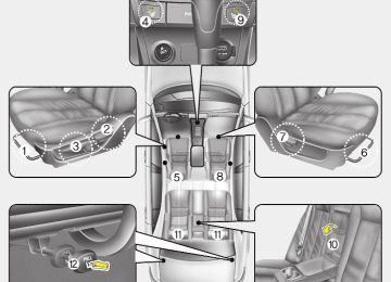
This vehicle has 2 fuse panels, one locat- ed in the driver’s side panel bolster, the other in the engine compartment near the battery. If any of your vehicle’s lights, acces- sories, or controls do not work, check the appropriate circuit fuse. If a fuse has blown, the element inside the fuse will be melted. If the electrical system does not work, first check the driver’s side fuse panel. Always replace a blown fuse with one of the same rating. If the replacement fuse blows, this indi- cates an electrical problem. Avoid using the system involved and immediately consult an authorized Hyundai dealer. Three kinds of fuses are used:blade type for lower amperage rating, cartridge type, and fusible link for higher amperage rat- ings.
WARNING - Fuse replace-
ment
(cid:129) Never replace a fuse with any- thing but another fuse of the same rating.
(cid:129) A higher capacity fuse could cause damage and possibly a fire.
(cid:129) Never install a wire instead of the proper fuse - even as a temporary repair. It may cause extensive wiring damage and a possible fire.
CAUTION
Do not use a screwdriver or any other metal object to remove fuses because it may cause a short circuit and damage the system.
FUSES Blade type
Normal
Blown
Cartridge type
Normal
Blown
Fusible link
Normal
Blown
1VQA4037
A vehicle’s electrical system is protected from electrical overload damage by fuses.7 45
Maintenance
Driver’s side panel
If the headlights or other electrical com- ponents do not work and the fuses are OK, check the fuse block in the engine compartment. If a fuse is blown, it must be replaced.
OHD076025
Inner panel fuse replacement 1. Turn the ignition switch and all other
switches off.
2. Open the fuse panel cover.
OHD076026
3. Pull the suspected fuse straight out. Use the removal tool provided on the main fuse box in the engine compart- ment.4. Check the removed fuse; replace it if it
is blown.
5. Push in a new fuse of the same rating, and make sure it fits tightly in the clips. If it fits loosely, consult an authorized Hyundai dealer. If you do not have a spare, use a fuse of the same rating from a circuit you may not need for operating the vehicle, such as the cigar lighter fuse.
46
✽✽ NOTICE • If the memory fuse is pulled up from the fuse panel, the warning chime, audio, clock and interior lamps, etc., will not operate. Some items must be reset after replacement. Refer to “Battery” in this section.
• Even though the memory fuse is pulled up, the battery can still be dis- charged by operation of the head- lights or other electrical devices.
OHD076027
Memory fuse Your vehicle is equipped with the memo- ry fuse to prevent battery discharge if your vehicle is parked without being operated for prolonged periods. Use the following procedures before parking the vehicle for prolonged periods.
1. Turn off the engine. 2. Turn off the headlights and tail lights. 3. Open the driver’s side panel cover and
pull up the memory fuse.
Maintenance
OHD076028
Engine compartment panel fuse replacement 1. Turn the ignition switch and all other
switches off.
2. Remove the fuse box cover by press-
ing the tap and pulling up.
3. Check the removed fuse; replace it if it is blown. To remove or insert the fuse, use the fuse puller in the main fuse box in the engine compartment.
4. Push in a new fuse of the same rating, and make sure it fits tightly in the clips. If it fits loosely, consult an authorized Hyundai dealer.
7 47
Maintenance
CAUTION
After checking the fuse box in the engine compartment, securely install the fuse box cover. If not, electrical failures may occur from water leaking in.
✽✽ NOTICE If the main fuse is blown, consult an Authorized Hyundai Dealer.
OHD076030
Main fuse If the main fuse is blown, it must be removed as follows: 1. Disconnect the negative battery cable. 2. Remove the nuts shown in the picture
above.
3. Replace the fuse with a new one of the
same rating.
4. Reinstall in the reverse order of
removal.
48
Fuse/Relay panel description Inside the fuse/relay box covers, you can find the fuse/relay label describing fuse/relay name and capacity.
Driver’s side panel
Engine compartment
✽✽ NOTICE Not all fuse panel descriptions in this manual may be applicable to your vehi- cle. It is accurate at the time of printing. When you inspect the fuse box on your vehicle, refer to the fuse box label.
Maintenance
OHD076031L/OHD076032
7 49
Maintenance
Driver's side fuse panel
Description
Fuse rating
10A 10A 10A 15A 10A 10A 25A 15A 15A 10A 25A 10A 15A 20A 15A 15A 15A 15A 15A 25A 25A 25A 15A 10A 10A
START A/CON SW HTD MIRR SEAT HTR A/CON HEAD LAMP FR WIPER RR WIPER DRL WCS P/WDW DR CLOCK C/LIGHTER DR LOCK DEICER STOP ROOM LP AUDIO T/LID AMP SAFETY P/WDW P/WDW ASS P/OUTLET T/SIG A/BAG IND
50
Protected component
Ignition lock switch, Antitheft alarm, Transaxle range switch A/C control module Outside heated mirror motor Seat warmer switch Blower relay, A/C control module, Sunroof control module Head lamp relay Front wiper relay (Spare) Daytime running lamp unit Occupant classification sensor Power window main switch, Rear power window switch(LH) Digital clock, Audio Power outlet Sunroof control module, Door unlock/lock relay Stop lamp switch Trunk room lamp, Dome lamp, Map lamp, Digital clock, Home link Audio Trunk lid relay Amplifier Safety power window module Front & rear power window switch(RH), Power window main switch Power outlet Hazard switch Airbag indicator(instrument cluster)
Description
Fuse rating
Protected component
CLUSTER A/BAG SPARE SPARE TAIL RH TAIL LH
10A 15A 15A 15A 10A 10A
Instrument cluster, EPS module, ESC switch SRS control module (Spare) (Spare) Head lamp(RH), Glove box lamp, Rear combination lamp(RH), License lamp Head lamp(LH), Power window main switch, Rear combination lamp(LH), License lamp
Maintenance
7 51
Maintenance
Engine compartment
Description
Fuse rating
Protected component
ALTERNATOR EPS ABS.2
ABS.1
B+.1Fusible link RR HTD BLOWER C/FAN B+.2
IGN.2
IGN.1
ECU SPARE.1
FR FOG A/CON HAZARD F/PUMP INJ SNSR.2
HORNFuse
125A 80A 20A 40A 50A 40A 40A 40A 50A 40A 30A 30A 20A 15A 10A 15A 15A 15A 10A 15A
Generator EPS control module ESC control module, ABS control module, Multi purpose check connector ESC control module, ABS control module, Multi purpose check connector Instrument panel junction box Instrument panel junction box Blower relay Condenser fan #1, 2 relay Instrument panel junction box Ignition switch, Start relay Ignition switch Main relay, ECM (Spare) Front fog lamp relay A/C relay Hazard switch, Hazard relay Fuel pump relay A/C relay, Fuel pump relay, Injector #1,2,3,4, ECM, Idle speed actuator etc. Pulse generator 'A', 'B’, Stop lamp switch, Vehicle speed sensor etc. Horn relay
52
Fuse
Description
Fuse rating
Protected component
ABS ECU.2
B/UP H/LP LO RH H/LP LO LH H/LP HI SNSR.1
SPARE SPARE SPARE10A 10A 10A 10A 10A 20A 10A 10A 15A 20A
ESC control module, ABS control module, Multi purpose check connector ECM Back up lamp switch, Transaxle range switch, Cruise control module Head lamp(RH) Head lamp(LH) Head lamp Hi relay Oxygen sensor, ECM, Mass air folw sensor etc. (Spare) (Spare) (Spare)
Maintenance
7 53
Maintenance
LIGHT BULBS
WARNING - Working on
the lights
Prior to working on the light, firmly apply the parking brake, ensure that the ignition switch is turned to the “LOCK” position and turn off the lights to avoid sudden move- ment of the vehicle and burning your fingers or receiving an electric shock.
Use only the bulbs of the specified wattage.
CAUTION
Be sure to replace the burned-out bulb with one of the same wattage rating. Otherwise, it may cause damage to the fuse or electric wiring system.
CAUTION
If you don’t have necessary tools, the correct bulbs and the expertise, consult an authorized Hyundai dealer.In many cases,it is difficult to replace vehicle light bulbs because other parts of the vehicle must be removed before you can get to the bulb. This is especially true if you have to remove the head- light assembly to get to the bulb(s). Removing/installing the headlight assembly can result in damage to the vehicle.
✽✽ NOTICE After heavy, driving rain or washing, headlight and taillight lenses could appear frosty. This condition is caused by the temperature difference between the lamp inside and outside. This is similar to the condensation on your windows inside your vehicle during the rain and doesn’t indicate a problem with your vehicle. If the water leaks into the lamp bulb cir- cuitry, have the vehicle checked by an authorized Hyundai dealer.
54
OHD076034
Headlight, position light, turn sig- nal light, front fog light bulb replacement (1) Headlight (High) (2) Headlight (Low) (3) Position light (4) Front turn signal light (5) Side mark light (6) Front fog light (if equipped)(Continued) (cid:129) If a bulb becomes damaged or cracked, replace it immediately and carefully dispose of it.
(cid:129) Wear eye protection when chang- ing a bulb. Allow the bulb to cool down before handling it.
Maintenance
OMG075038N
1. Open the hood. 2. Remove the headlight. 3. Remove the headlight bulb cover by
turning it counterclockwise.
4. Disconnect the headlight bulb assem-
bly by turning it counterclockwise.
5. Install a new headlight bulb assembly.
7 55
Headlight bulb
G270A030N
WARNING - Halogen bulbs (cid:129) Halogen bulbs contain pressur- ized gas that will produce flying pieces of glass if broken.
(cid:129) Always handle them carefully, and avoid scratches and abra- sions. If the bulbs are lit, avoid contact with liquids. Never touch the glass with bare hands. Residual oil may cause the bulb to overheat and burst when lit. A bulb should be operated only when installed in a headlight.
(Continued)
Maintenance
6. Install the headlight bulb cover by turn-
ing it clockwise.
7. Install the headlight.
Turn signal light/position light,side mark light,fog light bulb (if equipped) If the light bulb is not operating, have the vehicle checked by an authorized Hyundai dealer.
56
OHD076037
OHD076038
Rear combination light bulb replacement (1) Back-up light (2) Rear turn signal light (3) Stop and tail light (4) Side mark light
1. Open the trunk lid 2. Remove the service cover by pulling out
the service cover.
Maintenance
1JBA7031
OHD076040
High mounted stop light bulb replacement 1. Open the trunk lid. 2. Remove the socket by turning it coun-
terclockwise.
3. Replace the bulb from the socket. 4. Install the socket by turning it clock-
wise.
License plate light bulb replace- ment 1. Loosen the lens retaining screws with
a cross-tip screwdriver.
2. Remove the lens. 3. Remove the bulb by pulling it straight
out.
4. Install a new bulb. 5. Reinstall the lens securely with the
lens retaining screws.
OHD076039
3. Remove the socket from the assembly by turning the socket counterclockwise until the tabs on the socket align with the slots on the assembly.4. Remove the bulb from the socket by pressing it in and rotating it counter- clockwise until the tabs on the bulb align with the slots in the socket. Pull the bulb out of the socket.
5. Insert a new bulb by inserting it into the socket and rotating it until it locks into place.
6. Install the socket in the assembly by aligning the tabs on the socket with the slots in the assembly. Push the socket into the assembly and turn the socket clockwise.
7. Install the service cover by putting it
into the service hole.
7 57
3. Install a new bulb in the socket. 4. Align the lens tabs with the interior light housing notches and snap the lens into place.
CAUTION
Use care not to dirty or damage lens,lens tab,and plastic housings.
Maintenance
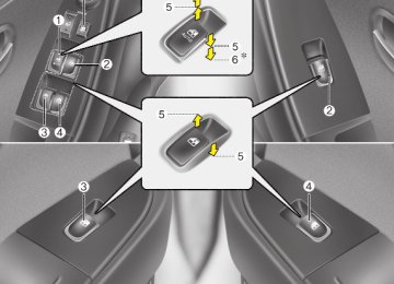
Front map lamp
Sunvisor lamp
Dome lamp
OHD076041
Glove box lamp
OHD076043
OHD076042
OHD076044
Interior light bulb replacement 1. Using a flat-blade screwdriver, gently pry the lens from the interior light housing.
2. Remove the bulb by pulling it straight
out.
WARNING
Prior to working on the Interior Lights, ensure that the “OFF” but- ton is depressed to avoid burning your fingers or receiving an electric shock.
58
APPEARANCE CARE Exterior care Exterior general caution It is very important to follow the label directions when using any chemical cleaner or polish. Read all warning and caution statements that appear on the label.
Finish maintenance Washing To help protect your vehicle’s finish from rust and deterioration, wash it thoroughly and frequently at least once a month with lukewarm or cold water. If you use your vehicle for off-road driv- ing, you should wash it after each off- road trip. Pay special attention to the removal of any accumulation of salt, dirt, mud, and other foreign materials. Make sure the drain holes in the lower edges of the doors and rocker panels are kept clear and clean.
Insects, tar, tree sap, bird droppings, industrial pollution and similar deposits can damage your vehicle’s finish if not removed immediately. Even prompt washing with plain water may not completely remove all these deposits. A mild soap, safe for use on painted surfaces, may be used. After washing, rinse the vehicle thor- oughly with lukewarm or cold water. Do not allow soap to dry on the finish.
CAUTION
Do not use strong soap, chemical detergents or hot water,and do not wash the vehicle in direct sunlight or when the body of the vehicle is warm.
Maintenance
WARNING - Wet brakes
After washing the vehicle, test the brakes while driving slowly to see if they have been affected by water. If braking performance is impaired, dry the brakes by applying them lightly while maintaining a slow for- ward speed.
CAUTION
(cid:129) Water washing in the engine com- partment may cause the failure of electrical circuits located in the engine compartment.
(cid:129) Never allow water or other liquids to come in contact with electri- cal/electronic components inside the vehicle as this may damage them.
7 59
Maintenance
Waxing Wax the vehicle when water will no longer bead on the paint. Always wash and dry the vehicle before waxing. Use a good quality liquid or paste wax, and follow the manufacturer’s instructions. Wax all metal trim to protect it and to maintain its luster. Removing oil, tar, and similar materials with a spot remover will usually strip the wax from the finish. Be sure to re-wax these areas even if the rest of the vehicle does not yet need waxing.
Finish damage repair Deep scratches or stone chips in the painted surface must be repaired promptly. Exposed metal will quickly rust and may develop into a major repair expense.
✽✽ NOTICE If your vehicle is damaged and requires any metal repair or replacement, be sure the body shop applies anti-corrosion materials to the parts repaired or replaced.
Bright-metal maintenance (cid:129) To remove road tar and insects, use a tar remover, not a scraper or other sharp object.
(cid:129) To protect the surfaces of bright-metal parts from corrosion, apply a coating of wax or chrome preservative and rub to a high luster.
(cid:129) During winter weather or in coastal areas, cover the bright metal parts with a heavier coating of wax or preserva- tive. If necessary, coat the parts with non-corrosive petroleum jelly or other protective compound.
CAUTION
(cid:129) Wiping dust or dirt off the body with a dry cloth will scratch the finish.
(cid:129) Do not use steel wool, abrasive cleaners, or strong detergents containing highly alkaline or caustic agents on chrome-plated or anodized aluminum parts.This may result in damage to the pro- tective coating and cause discol- oration or paint deterioration.
60
WARNING
After washing the vehicle, test the brakes while driving slowly to see if they have been affected by water. If braking performance is impaired, dry the brakes by applying them lightly while maintaining a slow for- ward speed.
Underbody maintenance Corrosive materials used for ice and snow removal and dust control may col- lect on the underbody. If these materials are not removed, accelerated rusting can occur on underbody parts such as the fuel lines, frame, floor pan and exhaust system, even though they have been treated with rust protection. Thoroughly flush the vehicle underbody and wheel openings with lukewarm or cold water once a month, after off-road driving and at the end of each winter. Pay special attention to these areas because it is difficult to see all the mud and dirt. It will do more harm than good to wet down the road grime without removing it. The lower edges of doors, rocker panels, and frame members have drain holes that should not be allowed to clog with dirt; trapped water in these areas can cause rusting.
Maintenance
Aluminum wheel maintenance The aluminum wheels are coated with a clear protective finish. (cid:129) Do not use any abrasive cleaner, pol- ishing compound, solvent, or wire brushes on aluminum wheels. They may scratch or damage the finish.
(cid:129) Use only a mild soap or neutral deter- gent, and rinse thoroughly with water. Also, be sure to clean the wheels after driving on salted roads. This helps pre- vent corrosion.
(cid:129) Avoid washing the wheels with high-
speed car wash brushes.
(cid:129) Do not use any acid detergent. It may damage and corrode the aluminum wheels coated with a clear protective finish.
7 61
High-corrosion areas If you live in an area where your car is regularly exposed to corrosive materials, corrosion protection is particularly impor- tant. Some of the common causes of accelerated corrosion are road salts, dust control chemicals, ocean air and industrial pollution.
Moisture breeds corrosion Moisture creates the conditions in which corrosion is most likely to occur. For example, corrosion is accelerated by high humidity, particularly when tempera- tures are just above freezing. In such conditions, the corrosive material is kept in contact with the car surfaces by mois- ture that is slow to evaporate. Mud is particularly corrosive because it is slow to dry and holds moisture in contact with the vehicle. Although the mud appears to be dry, it can still retain the moisture and promote corrosion. High temperatures can also accelerate corrosion of parts that are not properly ventilated so the moisture can be dis- persed. For all these reasons, it is par- ticularly important to keep your car clean and free of mud or accumulations of other materials. This applies not only to the visible surfaces but particularly to the underside of the car.
Maintenance
Corrosion protection Protecting your vehicle from corro- sion By using the most advanced design and construction practices to combat corro- sion, we produces cars of the highest quality. However, this is only part of the job. To achieve the long-term corrosion resistance your vehicle can deliver, the owner's cooperation and assistance is also required.
Common causes of corrosion The most common causes of corrosion on your car are: (cid:129) Road salt, dirt and moisture that is allowed to accumulate underneath the car.
(cid:129) Removal of paint or protective coatings by stones, gravel, abrasion or minor scrapes and dents which leave unpro- tected metal exposed to corrosion.
62
To help prevent corrosion You can help prevent corrosion from get- ting started by observing the following:
Keep your car clean The best way to prevent corrosion is to keep your car clean and free of corrosive materials. Attention to the underside of the car is particularly important.
(cid:129) If you live in a high-corrosion area — where road salts are used, near the ocean, areas with industrial pollution, acid rain, etc.—, you should take extra care to prevent corrosion. In winter, hose off the underside of your car at least once a month and be sure to clean the underside thoroughly when winter is over.
Maintenance
Keep paint and trim in good condition Scratches or chips in the finish should be covered with "touch-up" paint as soon as possible to reduce the possibility of cor- rosion. If bare metal is showing through, the attention of a qualified body and paint shop is recommended.
Bird droppings : Bird droppings are high- ly corrosive and may damage painted surfaces in just a few hours. Always remove bird droppings as soon as possi- ble.
Don't neglect the interior Moisture can collect under the floor mats and carpeting to cause corrosion. Check under the mats periodically to be sure the carpeting is dry. Use particular care if you carry fertilizers, cleaning materials or chemicals in the car. These should be carried only in proper containers and any spills or leaks should be cleaned up, flushed with clean water and thoroughly dried.
(cid:129) When cleaning underneath the car, give particular attention to the compo- nents under the fenders and other areas that are hidden from view. Do a thorough job; just dampening the accu- mulated mud rather than washing it away will accelerate corrosion rather than prevent it. Water under high pres- sure and steam are particularly effec- tive in removing accumulated mud and corrosive materials.
(cid:129) When cleaning lower door panels, rocker panels and frame members, be sure that drain holes are kept open so that moisture can escape and not be trapped inside to accelerate corrosion.
Keep your garage dry Don't park your car in a damp, poorly ventilated garage. This creates a favor-