- 1997 GMC Sierra Owners Manuals
- GMC Sierra Owners Manuals
- 2016 GMC Sierra Owners Manuals
- GMC Sierra Owners Manuals
- 2012 GMC Sierra Owners Manuals
- GMC Sierra Owners Manuals
- 2001 GMC Sierra Owners Manuals
- GMC Sierra Owners Manuals
- 2015 GMC Sierra Owners Manuals
- GMC Sierra Owners Manuals
- 2013 GMC Sierra Owners Manuals
- GMC Sierra Owners Manuals
- 2003 GMC Sierra Owners Manuals
- GMC Sierra Owners Manuals
- 2008 GMC Sierra Owners Manuals
- GMC Sierra Owners Manuals
- 2005 GMC Sierra Owners Manuals
- GMC Sierra Owners Manuals
- 1999 GMC Sierra Owners Manuals
- GMC Sierra Owners Manuals
- 2010 GMC Sierra Owners Manuals
- GMC Sierra Owners Manuals
- 2009 GMC Sierra Owners Manuals
- GMC Sierra Owners Manuals
- 1996 GMC Sierra Owners Manuals
- GMC Sierra Owners Manuals
- 2000 GMC Sierra Owners Manuals
- GMC Sierra Owners Manuals
- 2014 GMC Sierra Owners Manuals
- GMC Sierra Owners Manuals
- 2004 GMC Sierra Owners Manuals
- GMC Sierra Owners Manuals
- 2007 GMC Sierra Owners Manuals
- GMC Sierra Owners Manuals
- 1994 GMC Sierra Owners Manuals
- GMC Sierra Owners Manuals
- 2002 GMC Sierra Owners Manuals
- GMC Sierra Owners Manuals
- 2011 GMC Sierra Owners Manuals
- GMC Sierra Owners Manuals
- 1993 GMC Sierra Owners Manuals
- GMC Sierra Owners Manuals
- 2006 GMC Sierra Owners Manuals
- GMC Sierra Owners Manuals
- 1998 GMC Sierra Owners Manuals
- GMC Sierra Owners Manuals
- 1995 GMC Sierra Owners Manuals
- GMC Sierra Owners Manuals
- Download PDF Manual
-
Batteries have acid that can burn you and gas that can explode. You can be badly hurt if you are not careful. See Jump Starting on page 5-52
for tips on working around a battery without getting hurt.Batteries can hurt you. They can be dangerous because:
(cid:127) They contain acid that can burn you. (cid:127) They contain gas that can explode or ignite. (cid:127) They contain enough electricity to burn you. If you do not follow these steps exactly, some or all of these things can hurt you.
5-52
Ignoring these steps could result in costly
Notice: damage to your vehicle that would not be covered by your warranty. Trying to start your vehicle by pushing or pulling it will not work, and it could damage your vehicle. 1. Check the other vehicle. It must have a 12-volt
battery with a negative ground system.
If the other vehicle’s system is not a 12-volt
Notice: system with a negative ground, both vehicles can be damaged. Only use vehicles with 12-volt systems with negative grounds to jump start your vehicle.
2. If you have a vehicle with a diesel engine with two
batteries (or more), you should know before you begin that, especially in cold weather, you may not be able to get enough power from a single battery in another vehicle to start your diesel engine. If your vehicle has more than one battery, use the battery that is closer to the starter — this will reduce electrical resistance.
3. Get the vehicles close enough so the jumper cables can reach, but be sure the vehicles are not touching each other. If they are, it could cause a ground connection you do not want. You would not be able to start your vehicle, and the bad grounding could damage the electrical systems. To avoid the possibility of the vehicles rolling, set the parking brake firmly on both vehicles involved in the jump start procedure. Put an automatic transmission in PARK (P) or a manual transmission in NEUTRAL before setting the parking brake. If you have a four-wheel-drive vehicle, be sure the transfer case is in a drive gear, not in NEUTRAL.
If you leave your radio or other accessories
Notice: on during the jump starting procedure, they could be damaged. The repairs would not be covered by your warranty. Always turn off your radio and other accessories when jump starting your vehicle. 4. Turn off the ignition on both vehicles. Unplug
unnecessary accessories plugged into the cigarette lighter or accessory power outlets. Turn off the radio and all lamps that are not needed. This will avoid sparks and help save both batteries. And it could save the radio!
5-53
5. Open the hoods and locate the positive (+) and
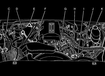
negative (−) terminal locations of the other vehicle. Your vehicle has a remote positive (+) jump starting terminal and a remote negative (−) jump starting terminal. You should always use these remote terminals instead of the terminals on the battery. The remote positive (+) terminal is located behind a red plastic cover, if equipped, near the engine accessory drive bracket. To uncover the remote positive (+) terminal, open the red plastic cover, if equipped. The remote negative (−) terminal is located on the engine drive bracket on all V8 and diesel engines, and on the thermostat housing on the 8.1L engine. On V8 engines it is marked GND (Ground). On V6 engines the remote negative (−) terminal is located on a tab attached to the engine accessory drive bracket where it is marked GND (Ground). See Engine Compartment Overview on page 5-14
for more information on the location of the remote positive (+) and remote negative (−) terminals.{CAUTION:
Using a match near a battery can cause battery gas to explode. People have been hurt doing this, and some have been blinded. Use a flashlight if you need more light. Be sure the battery has enough water. You do not need to add water to the battery installed in your new vehicle. But if a battery has filler caps, be sure the right amount of fluid is there. If it is low, add water to take care of that first. If you do not, explosive gas could be present. Battery fluid contains acid that can burn you. Do not get it on you. If you accidentally get it in your eyes or on your skin, flush the place with water and get medical help immediately.
5-54
{CAUTION:
Fans or other moving engine parts can injure you badly. Keep your hands away from moving parts once the engine is running.
6. Check that the jumper cables do not have loose or
missing insulation. If they do, you could get a shock. The vehicles could be damaged too. Before you connect the cables, here are some basic things you should know. Positive (+) will go to positive (+) or a remote positive terminal (+) if the vehicle has one. Negative (−) will go to a heavy, unpainted metal engine part or a remote negative (−) terminal if the vehicle has one. Do not connect positive (+) to negative (−) or you will get a short that would damage the battery and maybe other parts too. And do not connect the negative (−) cable to the negative (−) terminal on the dead battery because this can cause sparks. On vehicles equipped with dual batteries, make all battery connections to the remote positive (+) and remote negative (−) terminals.
7. Connect the red
positive (+) cable to the positive (+) terminal of the vehicle with the dead battery. Use a remote positive (+) terminal if the vehicle has one.
8. Do not let the other end touch metal. Connect it to the positive (+) terminal of the good battery. Use a remote positive (+) terminal if the vehicle has one. 9. Now connect the black negative (−) cable to the negative (−) terminal of the good battery. Use a remote negative (−) terminal if the vehicle has one. The vehicle’s remote negative (–) terminal is marked GND.
5-55
10. Do not let the other end touch anything until the next
step. The other end of the negative (−) cable does not go to the dead battery. It goes to a heavy unpainted metal engine part of the vehicle with the dead battery, or to a remote negative (–) terminal if the vehicle has one.
11. Connect the other end
of the negative (−) cable to the remote negative (−) terminal, marked GND, on the vehicle with the dead battery.
12. Now start the vehicle with the good battery and run
the engine for a while.
13. Try to start the vehicle that had the dead battery.
If it will not start after a few tries, it probably needs service.
If the jumper cables are connected or
Notice: removed in the wrong order, electrical shorting may occur and damage the vehicle. The repairs would not be covered by your warranty. Always connect and remove the jumper cables in the correct order, making sure that the cables do not touch each other or other metal.
V8 engine shown, other
engines similar
See Engine Compartment Overview on page 5-14
for the location of your vehicle’s remote negative (−) terminal.5-56
Jumper Cable Removal
A. Heavy, Unpainted Metal Engine Part or Remote
Negative (−) Terminal
B. Good Battery or Remote Positive (+) and Remote
Negative (−) Terminals
C. Dead Battery or Remote Positive (+) Terminal
To disconnect the jumper cables from both vehicles do the following: 1. Disconnect the black negative (−) cable from the
vehicle that had the bad battery.
2. Disconnect the black negative (−) cable from the
vehicle with the good battery.
3. Disconnect the red positive (+) cable from the
vehicle with the good battery.
4. Disconnect the red positive (+) cable from the
other vehicle.
5. Return the remote positive (+) terminal cover,
if equipped, to its original position.
5-57
Rear Axle When to Check Lubricant It is not necessary to regularly check rear axle fluid unless you suspect there is a leak or you hear an unusual noise. A fluid loss could indicate a problem. Have it inspected and repaired. All axle assemblies are filled by volume of fluid during production. They are not filled to reach a certain level. When checking the fluid level on any axle, variations in the readings can be caused by factory fill differences between the minimum and the maximum fluid volume. Also, if a vehicle has just been driven before checking the fluid level, it may appear lower than normal because fluid has traveled out along the axle tubes and has not drained back to the sump area. Therefore, a reading taken five minutes after the vehicle has been driven will appear to have a lower fluid level than a vehicle that has been stationary for an hour or two. Remember that the rear axle assembly must be supported to get a true reading.
5-58
How to Check Lubricant
1500 Series Shown, 2500 Series Similar
To get an accurate reading, the vehicle should be on a level surface.
The proper level for the 1500 Series is from 5/8 inch to 1 5/8 inch (15 mm to 40 mm) below the bottom of the filler plug hole. The proper level for the 1500HD Series, 2500 Series and 2500HD Series with the 6.0L V8 engine (RPO LQ4) is from 0 to 1/2 inch (0 to 13 mm) below the bottom of the filler plug hole.
(cid:127) (cid:127) The proper level for the 2500HD with the 6.6L diesel engine (RPO LLY) or 8.1L V8 engine (RPO L18), and 3500 Series is from 0.6 to 0.8 inch (17 mm to 21 mm) below the bottom of the filler plug hole.
Add only enough fluid to reach the proper level. What to Use To determine what kind of lubricant to use see Recommended Fluids and Lubricants (Gasoline Engine) on page 6-14. Four-Wheel Drive Lubricant checks in this section also apply to these vehicles. There are two additional systems that need lubrication. Transfer Case When to Check Lubricant It is not necessary to regularly check transfer case fluid unless you suspect there is a leak or you hear an unusual noise. A fluid loss could indicate a problem. Have it inspected and repaired.
How to Check Lubricant
Manual Transfer Case
5-59
(cid:127) When to Change Lubricant Refer to the Maintenance Schedule to determine how often to change the lubricant. See Scheduled Maintenance (Gasoline Engine) on page 6-4. What to Use Refer to the Maintenance Schedule to determine what kind of lubricant to use. See Recommended Fluids and Lubricants (Gasoline Engine) on page 6-14. Front Axle When to Check Lubricant It is not necessary to regularly check front axle fluid unless you suspect there is a leak or you hear an unusual noise. A fluid loss could indicate a problem. Have it inspected and repaired.
Automatic Transfer Case
To get an accurate reading, the vehicle should be on a level surface. If the level is below the bottom of the filler plug hole, located on the transfer case, you’ll need to add some lubricant. Add enough lubricant to raise the level to the bottom of the filler plug hole. Use care not to overtighten the plug.
5-60
How to Check Lubricant
If the level is below the bottom of the filler plug hole, located on the front axle, you may need to add some lubricant: (cid:127) When the differential is cold, add enough lubricant to
raise the level to 0 to 3/8 inch (9.5 mm) below the filler plug hole.
(cid:127) When the differential is at operating temperature
(warm), add enough lubricant to raise the level to the bottom of the filler plug hole.
What to Use To determine what kind of lubricant to use see Recommended Fluids and Lubricants (Gasoline Engine) on page 6-14.
To get an accurate reading, the vehicle should be on a level surface.
5-61
Noise Control System Tampering with Noise Control System Prohibited The following information relates to compliance with federal noise emission standards for vehicles with a Gross Vehicle Weight Rating (GVWR) of more than 10,000 lbs (4 536 kg). The Maintenance Schedule provides information on maintaining the noise control system to minimize degradation of the noise emission control system during the life of your vehicle. The noise control system warranty is given in your warranty booklet. These standards apply only to vehicles sold in the United States. Federal law prohibits the following acts or the causing thereof: 1. The removal or rendering inoperative by any person,
other than for purposes of maintenance, repair or replacement, of any device or element of design incorporated into any new vehicle for the purpose of noise control, prior to its sale or delivery to the ultimate purchaser or while it is in use; or
2. The use of the vehicle after such device or element of design has been removed or rendered inoperative by any person.
Among those acts presumed to constitute tampering are the acts listed below. Insulation: (cid:127) Removal of the noise shields or any underhood
insulation.
Engine: (cid:127) Removal or rendering engine speed governor (if equipped) inoperative so as to allow engine speed to exceed manufacturer specifications.
Fan and Drive: (cid:127) Removal of fan clutch (if equipped) or rendering
clutch inoperative.
(cid:127) Removal of the fan shroud (if equipped). Air Intake: (cid:127) Removal of the air cleaner silencer. (cid:127) Modification of the air cleaner. Exhaust: (cid:127) Removal of the muffler and/or resonator. (cid:127) Removal of the exhaust pipes and exhaust pipe
clamps.
5-62
Bulb Replacement For the proper type of replacement bulbs, see Replacement Bulbs on page 5-70. For any bulb changing procedure not listed in this section, contact your dealer.
Headlamps To replace a headlamp bulb, do the following: 1. Open the hood. See Hood Release on page 5-13
for more information.
Halogen Bulbs
{CAUTION:
Halogen bulbs have pressurized gas inside and can burst if you drop or scratch the bulb. You or others could be injured. Be sure to read and follow the instructions on the bulb package.
2. Remove the two pins on the top of the headlamp assembly. To remove the pins, turn the outer pin outward and pull it straight up. To remove the inner pin, turn it in and pull it straight up.
5-63
Front Turn Signal, Sidemarker and Daytime Running Lamps
A. Low-Beam Headlamp B. High-Beam Headlamp
3. Pull the headlamp assembly out. 4. Unplug the electrical connector. 5. Turn the old bulb counterclockwise and remove it
from the headlamp assembly.
6. Install the new bulb into the assembly and turn it
clockwise until it is tight.
7. Plug in the electrical connector. 8. Reinstall the headlamp assembly. 9. Reinstall and tighten the two pins.
5-64
A. Sidemarker Lamp B. Retainer Clip C. Front Turn Signal Lamp D. Daytime Running Lamp (DRL)
To replace a front turn signal, sidemarker or DRL bulb, do the following: 1. Open the hood. See Hood Release on page 5-13
for more information.
2. Remove the headlamp assembly as described
previously. See Headlamps on page 5-63 for more information.
4. Pull the turn signal assembly out of the vehicle. 5. Press the locking release lever, turn the bulb socket counterclockwise and remove it from the turn signal assembly.
6. Remove the old bulb from the bulb socket. 7. Install a new bulb into the bulb socket. 8. Insert the bulb socket into the turn signal assembly
and turn it clockwise until it locks.
9. Reinstall the turn signal assembly back into the
vehicle placing the hook and posts on the inner side into the alignment holes first, then the outer side into the retainer bracket until you hear a click.
10. Reinstall the headlamp assembly.
3. Press the retainer clip (B), located behind the turn
signal assembly, towards the outside of the vehicle.
5-65
Roof Marker Lamps To replace a roof marker lamp bulb, do the following:
To replace a center roof marker lamp bulb, do the following:
1. Remove the
two screws and lift off the lens.
2. Install a new bulb into
the socket and turn clockwise until it locks into place.
1. Remove the six screws from the center roof marker
lamp assembly.
2. Turn the old bulb counterclockwise to remove it
from the socket.
3. Reinstall the lens and tighten the screws.
3. Reinstall the lens and tighten the screws.
5-66
Center High-Mounted Stoplamp (CHMSL) and Cargo Lamp To replace one of these bulbs, do the following:
1. Remove the screws and lift off the lamp assembly.
A. Cargo Lamp B. Center High-Mounted Stoplamp Bulb
2. Remove the back plate from the assembly by
pressing the release tabs.
3. Remove the CHMSL bulb by pulling the bulb
straight out from the holder back plate. Remove a cargo bulb by turning the socket counterclockwise and pulling the bulb straight out.
5-67
Taillamps, Turn Signal, Stoplamps and Back-up Lamps To replace one of these bulbs, do the following: 1. Open the tailgate. Tailgate on page 2-14 for more
information.
2. Remove the two rear
lamp assembly screws near the tailgate latch and pull out the lamp assembly.
4. If a CHMSL bulb is replaced, put the new bulb into
the socket and press it in until it is tight. If a cargo lamp is replaced, put a new cargo lamp bulb into the socket and press it in until it is tight before turning the socket counterclockwise.
5. Reinstall the back plate into the lamp assembly. 6. Reinstall the lamp assembly and tighten the screws.
Pickup Box Identification and Fender Marker Lamps To replace a pickup box identification or fender marker lamp bulb, do the following: 1. Remove the screws and lamp assembly. 2. Unplug the lamp assembly harness. 3. Gently pry the individual lamp from the lamp
assembly.
4. Unplug the lamp. 5. Plug in a new lamp and snap it into the assembly. 6. Reinstall the lamp assembly.
5-68
3. Determine which of the following taillamp assembly
applies to your vehicle.
A. Stoplamp/Taillamp B. Turn Signal C. Back-up Lamp
A. Stoplamp/Taillamp B. Turn Signal Lamp C. Back-up Lamp D. Sidemarker Lamp
4. Press the release tab, if equipped, and turn the bulb socket counterclockwise to remove it from the taillamp assembly.
5. Pull the old bulb straight out from the socket. 6. Press a new bulb into the socket and turn the socket
clockwise into the taillamp assembly.
7. Reinstall the taillamp assembly.
5-69
Taillamps (Chassis Cab Models)
Replacement Bulbs
A. Turn Signal Lamp B. Taillamp/Stoplamp C. Back-up Lamp
To replace one of these bulbs, do the following:
1. Peel the rubber seal away from the lens using
your hands.
2. Lift the lens off the lamp assembly. 3. Pull the old bulb straight out from the socket. 4. Install a new bulb into the socket and press it in
until it is tight.
5. Reinstall the lens and the lens seal.
5-70
Exterior Lamp
Bulb Number
Back-up Lamp Back-up Lamp* Cargo Lamp and Center High-Mounted Stoplamp (CHMSL) Daytime Running Lamps (DRL) Fender Marker, Front Roof Marker and Sidemarker Lamp (If Equipped) Front Parking and Turn Lamp Headlamps High-Beam Low-Beam Rear Marker Lamp, Taillamp and Stoplamp* Rear Turn Signal Lamp Rear Turn Signal Lamp* Stoplamp and Taillamp* * Chassis Cab Models
3157
1156912
4114K
194
3457A
9005
90063157
3157
1156
1157For replacement bulbs not listed here, contact your dealer.
Windshield Wiper Blade Replacement Windshield wiper blades should be inspected for wear and cracking. See Scheduled Maintenance (Gasoline Engine) on page 6-4 for more information. Replacement blades come in different types and are removed in different ways. For proper type and length, see Normal Maintenance Replacement Parts (Gasoline Engines) on page 6-18.
2. Push the release lever (B) to disengage the hook and push the wiper arm (A) out of the blade (C).
3. Push the new wiper blade securely on the wiper arm
until you hear the release lever click into place.
To replace the windshield wiper blade assembly do the following: 1. Lift the wiper arm away from the windshield.
5-71
Tires Your new vehicle comes with high-quality tires made by a leading tire manufacturer. If you ever have questions about your tire warranty and where to obtain service, see your GM Warranty booklet for details. For additional information refer to the tire manufacturer’s booklet included with your vehicle’s Owner’s Manual.
{CAUTION:
Poorly maintained and improperly used tires are dangerous.
(cid:127) Overloading your tires can cause
overheating as a result of too much friction. You could have an air-out and a serious accident. See Loading Your Vehicle on page 4-48.
CAUTION:
(Continued)
5-72
CAUTION:
(Continued)
(cid:127) Underinflated tires pose the same danger as overloaded tires. The resulting accident could cause serious injury. Check all tires frequently to maintain the recommended pressure. Tire pressure should be checked when your tires are cold. See Inflation - Tire Pressure on page 5-79.
(cid:127) Overinflated tires are more likely to be cut, punctured, or broken by a sudden impact — such as when you hit a pothole. Keep tires at the recommended pressure.
(cid:127) Worn, old tires can cause accidents. If your
tread is badly worn, or if your tires have been damaged, replace them.
20-Inch Tires If your vehicle has the optional 20-inch P275/55R20 size tires, they are classified as touring tires and are designed for on road use. The low-profile, wide tread design is not recommended for “off-road” driving or commercial uses such as snow plowing. See Off-Road Driving on page 4-16 and Adding a Snow Plow or Similar Equipment on page 4-54 for additional information.
Tire Sidewall Labeling Useful information about a tire is molded into the sidewall. The following illustrations are examples of a typical P-Metric and a LT-Metric tire sidewall.
Passenger (P-Metric) Tire
(A) Tire Size: The tire size code is a combination of letters and numbers used to define a particular tire’s width, height, aspect ratio, construction type and service description. See the “Tire Size” illustration later in this section for more detail.
(B) TPC Spec (Tire Performance Criteria Specification): Original equipment tires designed to GM’s specific tire performance criteria have a TPC specification code molded onto the sidewall. GM’s TPC specifications meet or exceed all federal safety guidelines. (C) DOT (Department of Transportation): The Department of Transportation (DOT) code indicates that the tire is in compliance with the U.S. Department of Transportation Motor Vehicle Safety Standards. (D) Tire Identification Number (TIN): The letters and numbers following DOT code are the Tire Identification Number (TIN). The TIN shows the manufacturer and plant code, tire size, and date the tire was manufactured. The TIN is molded onto both sides of the tire, although only one side may have the date of manufacture. (E) Tire Ply Material: The type of cord and number of plies in the sidewall and under the tread. (F) Uniform Tire Quality Grading (UTQG): Tire manufacturers are required to grade tires based on three performance factors: treadwear, traction and temperature resistance. For more information, see Uniform Tire Quality Grading on page 5-86. (G) Maximum Cold Inflation Load Limit: Maximum load that can be carried and the maximum pressure needed to support that load. For information on recommended tire pressure see Inflation - Tire Pressure on page 5-79 and Loading Your Vehicle on page 4-48.
5-73
(C) Dual Tire Maximum Load: Maximum load that can be carried and the maximum pressure needed to support that load when used in a dual configuration. For information on recommended tire pressure see Inflation - Tire Pressure on page 5-79 and Loading Your Vehicle on page 4-48.
(D) DOT (Department of Transportation): The Department of Transportation (DOT) code indicates that the tire is in compliance with the U.S. Department of Transportation Motor Vehicle Safety Standards.
(E) Tire Identification Number (TIN): The letters and numbers following DOT code are the Tire Identification Number (TIN). The TIN shows the manufacturer and plant code, tire size, and date the tire was manufactured. The TIN is molded onto both sides of the tire, although only one side may have the date of manufacture.
(F) Tire Ply Material: The type of cord and number of plies in the sidewall and under the tread.
(G) Single Tire Maximum Load: Maximum load that can be carried and the maximum pressure needed to support that load when used as a single. For information on recommended tire pressure see Inflation - Tire Pressure on page 5-79 and Loading Your Vehicle on page 4-48.
Light Truck (LT-Metric) Tire
(A) Tire Size: The tire size code is a combination of letters and numbers used to define a particular tire’s width, height, aspect ratio, construction type and service description. See the “Tire Size” illustration later in this section for more detail. (B) TPC Spec (Tire Performance Criteria Specification): Original equipment tires designed to GM’s specific tire performance criteria have a TPC specification code molded onto the sidewall. GM’s TPC specifications meet or exceed all federal safety guidelines.
5-74
Tire Size The following examples show the different parts of a tire size.
Passenger (P-Metric) Tire
Light Truck (LT-Metric) Tire
(A) Passenger (P-Metric) Tire: The United States version of a metric tire sizing system. The letter P as the first character in the tire size means a passenger vehicle tire engineered to standards set by the U.S. Tire and Rim Association.
(A) Light Truck (LT-Metric) Tire: The United States version of a metric tire sizing system. The letters LT as the first two characters in the tire size means a light truck tire engineered to standards set by the U.S. Tire and Rim Association.
(B) Tire Width: The three-digit number indicates the tire section width in millimeters from sidewall to sidewall.
(C) Aspect Ratio: A two-digit number that indicates the tire height-to-width measurements. For example, if the tire size aspect ratio is 75, as shown in item C of the light truck (LT-Metric) tire illustration, it would mean that the tire’s sidewall is 75% as high as it is wide.
(D) Construction Code: A letter code is used to indicate the type of ply construction in the tire. The letter R means radial ply construction; the letter D means diagonal or bias ply construction; and the letter B means belted-bias ply construction.
(E) Rim Diameter: Diameter of the wheel in inches.
(F) Service Description: The service description indicates the load range and speed rating of a tire. The load index can range from 1 to 279. Speed ratings range from A to Z.
5-75
Tire Terminology and Definitions Air Pressure: The amount of air inside the tire pressing outward on each square inch of the tire. Air pressure is expressed in pounds per square inch (psi) or kilopascal (kPa). Accessory Weight: This means the combined weight of optional accessories. Some examples of optional accessories are, automatic transmission, power steering, power brakes, power windows, power seats, and air conditioning. Aspect Ratio: The relationship of a tire’s height to its width. Belt: A rubber coated layer of cords that is located between the plies and the tread. Cords may be made from steel or other reinforcing materials. Bead: The tire bead contains steel wires wrapped by steel cords that hold the tire onto the rim. Bias Ply Tire: A pneumatic tire in which the plies are laid at alternate angles less than 90 degrees to the centerline of the tread.
Cold Inflation Pressure: The amount of air pressure in a tire, measured in pounds per square inch (psi) or kilopascals (kPa) before a tire has built up heat from driving. See Inflation - Tire Pressure on page 5-79.
Curb Weight: This means the weight of a motor vehicle with standard and optional equipment including the maximum capacity of fuel, oil and coolant, but without passengers and cargo.
DOT Markings: A code molded into the sidewall of a tire signifying that the tire is in compliance with the U.S. Department of Transportation (DOT) motor vehicle safety standards. The DOT code includes the Tire Identification Number (TIN), an alphanumeric designator which can also identify the tire manufacturer, production plant, brand and date of production.
GVWR: Gross Vehicle Weight Rating, see Loading Your Vehicle on page 4-48.
GAWR FRT: Gross Axle Weight Rating for the front axle, see Loading Your Vehicle on page 4-48.
GAWR RR: Gross Axle Weight Rating for the rear axle, see Loading Your Vehicle on page 4-48.
5-76
Intended Outboard Sidewall: The side of an asymmetrical tire, that must always face outward when mounted on a vehicle.
Kilopascal (kPa): The metric unit for air pressure.
Light Truck (LT-Metric) Tire: A tire used on light duty trucks and some multipurpose passenger vehicles.
Load Index: An assigned number ranging from 1 to 279
that corresponds to the load carrying capacity of a tire.Maximum Inflation Pressure: The maximum air pressure to which a cold tire may be inflated. The maximum air pressure is molded onto the sidewall.
Maximum Load Rating: The load rating for a tire at the maximum permissible inflation pressure for that tire.
Maximum Loaded Vehicle Weight: The sum of curb weight; accessory weight; vehicle capacity weight; and production options weight.
Normal Occupant Weight: The number of occupants a vehicle is designed to seat multiplied by 150 lbs (68 kg). See Loading Your Vehicle on page 4-48.
Occupant Distribution: Designated seating positions.
Outward Facing Sidewall: The side of an asymmetrical tire that has a particular side that faces outward when mounted on a vehicle. The side of the tire that contains a whitewall, bears white lettering, or bears manufacturer, brand, and/or model name molding that is higher or deeper than the same moldings on the other sidewall of the tire.
Passenger (P-Metric) Tire: A tire used on passenger cars and some light duty trucks and multipurpose vehicles.
Recommended Inflation Pressure: Vehicle manufacturer’s recommended tire inflation pressure and shown on the tire placard. See Inflation - Tire Pressure on page 5-79 and Loading Your Vehicle on page 4-48.
Radial Ply Tire: A pneumatic tire in which the ply cords that extend to the beads are laid at 90 degrees to the centerline of the tread.
Rim: A metal support for a tire and upon which the tire beads are seated.
Sidewall: The portion of a tire between the tread and the bead.
5-77
Speed Rating: An alphanumeric code assigned to a tire indicating the maximum speed at which a tire can operate.
Traction: The friction between the tire and the road surface. The amount of grip provided.
Tread: The portion of a tire that comes into contact with the road.
Treadwear Indicators: Narrow bands, sometimes called wear bars, that show across the tread of a tire when only 1/16 inch (1.6 mm) of tread remains. See When It Is Time for New Tires on page 5-83.
UTQGS (Uniform Tire Quality Grading Standards): A tire information system that provides consumers with ratings for a tire’s traction, temperature, and treadwear. Ratings are determined by tire manufacturers using government testing procedures. The ratings are molded into the sidewall of the tire. See Uniform Tire Quality Grading on page 5-86.
Vehicle Capacity Weight: The number of designated seating positions multiplied by 150 lbs (68 kg) plus the rated cargo load. See Loading Your Vehicle on page 4-48.
Vehicle Maximum Load on the Tire: Load on an individual tire due to curb weight, accessory weight, occupant weight, and cargo weight.
Vehicle Placard: A label permanently attached to a vehicle showing the vehicle’s capacity weight and the original equipment tire size and recommended inflation pressure. See “Tire and Loading Information Label” under Loading Your Vehicle on page 4-48.
5-78
Inflation - Tire Pressure Tires need the correct amount of air pressure to operate effectively. Notice: Do not let anyone tell you that under-inflation or over-inflation is all right. It is not. If your tires do not have enough air (under-inflation), you can get the following:
Too much flexing Too much heat Tire overloading
(cid:127) Premature or irregular wear (cid:127) Poor handling (cid:127) Reduced fuel economy If your tires have too much air (over-inflation), you can get the following: (cid:127) Unusual wear (cid:127) Poor handling (cid:127) Rough ride (cid:127) Needless damage from road hazards
A Tire and Loading Information label is attached to the vehicle’s center pillar (B-pillar), below the driver’s door lock post (striker). This label lists your vehicle’s original equipment tires and their recommended cold tire inflation pressures. The recommended cold tire inflation pressure, shown on the label, is the minimum amount of air pressure needed to support your vehicle’s maximum load carrying capacity. For additional information regarding how much weight your vehicle can carry, and an example of the tire and loading information label, see Loading Your Vehicle on page 4-48. When to Check Check your tires once a month or more. Do not forget to check the spare tire. For additional information regarding the spare tire, see Spare Tire on page 5-112.
5-79
(cid:127) (cid:127) (cid:127) How to Check Use a good quality pocket-type gage to check tire pressure. You cannot tell if your tires are properly inflated simply by looking at them. Radial tires may look properly inflated even when they’re underinflated. Check the tire’s inflation pressure when the tires are cold. Cold means your vehicle has been sitting for at least three hours or driven no more than 1 mile (1.6 km). Remove the valve cap from the tire valve stem. Press the tire gage firmly onto the valve to get a pressure measurement. If the cold tire inflation pressure matches the recommended pressure on the Tire and Loading Information label, no further adjustment is necessary. If the inflation pressure is low, add air until you reach the recommended amount. If you overfill the tire, release air by pushing on the metal stem in the center of the tire valve. Recheck the tire pressure with the tire gage. Be sure to put the valve caps back on the valve stems. They help prevent leaks by keeping out dirt and moisture.
Dual Tire Operation When the vehicle is new, or whenever a wheel, wheel bolt or wheel nut is replaced, check the wheel nut torque after 100, 1,000 and 6,000 miles (160, 1 600 and 10 000 km) of driving. For proper torque and wheel nut tightening information, see Removing the Spare Tire and Tools on page 5-92. The outer tire on a dual wheel setup generally wears faster than the inner tire. Your tires will wear more evenly and last longer if you rotate the tires periodically, see Tire Inspection and Rotation on page 5-81. Also see Scheduled Maintenance (Gasoline Engine) on page 6-4.
{CAUTION:
If you operate your vehicle with a tire that is badly underinflated, the tire can overheat. An overheated tire can lose air suddenly or catch fire. You or others could be injured. Be sure all tires (including the spare) are properly inflated.
See Inflation - Tire Pressure on page 5-79, for information on proper tire inflation.
5-80
Tire Inspection and Rotation Tires should be rotated every 5,000 to 8,000 miles (8 000 to 13 000 km). Any time you notice unusual wear, rotate your tires as soon as possible and check wheel alignment. Also check for damaged tires or wheels. See When It Is Time for New Tires on page 5-83 and Wheel Replacement on page 5-87 for more information. Make sure the spare tire is stored securely. Push, pull, and then try to rotate or turn the tire. If it moves, use the wheel wrench/hoist shaft to tighten the cable. See Changing a Flat Tire on page 5-91. If your vehicle has dual rear wheels, also see Dual Tire Operation on page 5-80.
The purpose of regular rotation is to achieve more uniform wear for all tires on the vehicle. The first rotation is the most important. See Scheduled Maintenance (Gasoline Engine) on page 6-4.
If your vehicle has single rear wheels and the tread design for your front tires is the same as your rear tires, use the rotation pattern shown here when rotating your tires.
5-81
If your vehicle has dual rear wheels and the tread design for the front tires is different from the dual rear tires, always use the correct rotation pattern shown here when rotating your tires.
If your vehicle has dual rear wheels and the tread design for your front tires is the same as your rear tires, always use one of the correct rotation patterns shown here when rotating your tires.
The dual tires are rotated as a pair, and the inside rear tires become the outside rear tires. When you install dual wheels, be sure the vent holes in the inner and outer wheels on each side are lined up. After the tires have been rotated, adjust the front and rear inflation pressures as shown on the Tire and Loading Information label. See Loading Your Vehicle on page 4-48.
5-82
Make certain that all wheel nuts are properly tightened. See “Wheel Nut Torque” under Capacities and Specifications on page 5-133.
{CAUTION:
Rust or dirt on a wheel, or on the parts to which it is fastened, can make wheel nuts become loose after a time. The wheel could come off and cause an accident. When you change a wheel, remove any rust or dirt from places where the wheel attaches to the vehicle. In an emergency, you can use a cloth or a paper towel to do this; but be sure to use a scraper or wire brush later, if needed, to get all the rust or dirt off. See Changing a Flat Tire on page 5-91.
When It Is Time for New Tires
One way to tell when it is time for new tires is to check the treadwear indicators, which will appear when your tires have only 1/16 inch (1.6 mm) or less of tread remaining. Some commercial truck tires may not have treadwear indicators.
You need a new tire if any of the following statements are true: (cid:127) You can see the indicators at three or more places
around the tire.
(cid:127) You can see cord or fabric showing through the
tire’s rubber. The tread or sidewall is cracked, cut or snagged deep enough to show cord or fabric. The tire has a bump, bulge, or split. The tire has a puncture, cut, or other damage that cannot be repaired well because of the size or location of the damage.
5-83
(cid:127) (cid:127) (cid:127) Buying New Tires GM has developed and matched specific tires for your vehicle. The original equipment tires installed on your vehicle, when it was new, were designed to meet General Motors Tire Performance Criteria Specification (TPC spec) system rating. If you need replacement tires, GM strongly recommends that you get tires with the same TPC Spec rating. This way, your vehicle will continue to have tires that are designed to give the same performance and vehicle safety, during normal use, as the original tires. GM’s exclusive TPC Spec system considers over a dozen critical specifications that impact the overall performance of your vehicle, including brake system performance, ride and handling, traction control, and tire pressure monitoring performance. GM’s TPC Spec number is molded onto the tire’s sidewall by the tire manufacturer. If the tires have an all-season tread design, the TPC spec number will be followed by an MS for mud and snow. See Tire Sidewall Labeling on page 5-73 for additional information.
{CAUTION:
Mixing tires could cause you to lose control while driving. If you mix tires of different sizes, brands or types (radial and bias-belted tires), the vehicle may not handle properly, and you could have a crash. Using tires of different sizes, brands or types may also cause damage to your vehicle. Be sure to use the same size, brand, and type tires on all wheels. Your vehicle may have a different size spare than the road tires (those originally installed on your vehicle). When new, your vehicle included a spare tire and wheel assembly with a similar overall diameter as your vehicle’s road tires and wheels, so it is all right to drive on it. Because this spare was developed for use on your vehicle, it will not affect vehicle handling.
5-84
{CAUTION:
If you use bias-ply tires on your vehicle, the wheel rim flanges could develop cracks after many miles of driving. A tire and/or wheel could fail suddenly, causing a crash. Use only radial-ply tires with the wheels on your vehicle.
If you must replace your vehicle’s tires with those that do not have a TPC Spec number, make sure they are the same size, load range, speed rating, and construction type (radial and bias-belted tires) as your vehicle’s original tires. Your vehicle’s original equipment tires are listed on the Tire and Loading Information Label. This label is attached to the vehicle’s center pillar (B-pillar). See Loading Your Vehicle on page 4-48, for more information about the Tire and Loading Information Label and its location on your vehicle.
Different Size Tires and Wheels If you add wheels or tires that are a different size than your original equipment wheels and tires, this may affect the way your vehicle performs, including its braking, ride and handling characteristics, stability and resistance to rollover. Additionally, if your vehicle has electronic systems such as, antilock brakes; traction control; and electronic stability control, the performance of these systems can be affected.
{CAUTION:
If you add different sized wheels, your vehicle may not provide an acceptable level of performance and safety if tires not recommended for those wheels are selected. You may increase the chance that you will crash and suffer serious injury. Only use GM specific wheel and tire systems developed for your vehicle, and have them properly installed by a GM certified technician.
See Buying New Tires on page 5-84 and Accessories and Modifications on page 5-4 for additional information.
5-85
Uniform Tire Quality Grading Quality grades can be found where applicable on the tire sidewall between tread shoulder and maximum section width. For example: Treadwear 200 Traction AA Temperature A The following information relates to the system developed by the United States National Highway Traffic Safety Administration, which grades tires by treadwear, traction and temperature performance. (This applies only to vehicles sold in the United States.) The grades are molded on the sidewalls of most passenger car tires. The Uniform Tire Quality Grading system does not apply to deep tread, winter-type snow tires, space-saver or temporary use spare tires, tires with nominal rim diameters of 10 to 12 inches (25 to 30 cm), or to some limited-production tires. While the tires available on General Motors passenger cars and light trucks may vary with respect to these grades, they must also conform to federal safety requirements and additional General Motors Tire Performance Criteria (TPC) standards.
Treadwear The treadwear grade is a comparative rating based on the wear rate of the tire when tested under controlled conditions on a specified government test course. For example, a tire graded 150 would wear one and a half (1.5) times as well on the government course as a tire graded 100. The relative performance of tires depends upon the actual conditions of their use, however, and may depart significantly from the norm due to variations in driving habits, service practices and differences in road characteristics and climate. Traction – AA, A, B, C The traction grades, from highest to lowest, are AA, A, B, and C. Those grades represent the tire’s ability to stop on wet pavement as measured under controlled conditions on specified government test surfaces of asphalt and concrete. A tire marked C may have poor traction performance. Warning: The traction grade assigned to this tire is based on straight-ahead braking traction tests, and does not include acceleration, cornering, hydroplaning, or peak traction characteristics.
5-86
Temperature – A, B, C The temperature grades are A (the highest), B, and C, representing the tire’s resistance to the generation of heat and its ability to dissipate heat when tested under controlled conditions on a specified indoor laboratory test wheel. Sustained high temperature can cause the material of the tire to degenerate and reduce tire life, and excessive temperature can lead to sudden tire failure. The grade C corresponds to a level of performance which all passenger car tires must meet under the Federal Motor Vehicle Safety Standard No. 109. Grades B and A represent higher levels of performance on the laboratory test wheel than the minimum required by law. Warning: The temperature grade for this tire is established for a tire that is properly inflated and not overloaded. Excessive speed, underinflation, or excessive loading, either separately or in combination, can cause heat buildup and possible tire failure.
Wheel Alignment and Tire Balance The tires and wheels on your vehicle were aligned and balanced carefully at the factory to give you the longest tire life and best overall performance. Adjustments to wheel alignment and tire balancing will not be necessary on a regular basis. However, if you notice unusual tire wear or your vehicle pulling to one side or the other, the alignment may need to be checked. If you notice your vehicle vibrating when driving on a smooth road, your tires and wheels may need to be rebalanced. See your dealer for proper diagnosis.
Wheel Replacement Replace any wheel that is bent, cracked, or badly rusted or corroded. If wheel nuts keep coming loose, the wheel, wheel bolts and wheel nuts should be replaced. If the wheel leaks air, replace it (except some aluminum wheels, which can sometimes be repaired). See your dealer if any of these conditions exist. Your dealer will know the kind of wheel you need.
5-87
Whenever a wheel, wheel bolt or wheel nut is replaced on a dual wheel setup, check the wheel nut torque after 100, 1,000 and 6,000 miles (160, 1 600 and 10 000 km) of driving. For proper torque, see “Wheel Nut Torque” under Capacities and Specifications on page 5-133. See Changing a Flat Tire on page 5-91 for more information. Used Replacement Wheels
{CAUTION:
Putting a used wheel on your vehicle is dangerous. You cannot know how it has been used or how far it has been driven. It could fail suddenly and cause a crash. If you have to replace a wheel, use a new GM original equipment wheel.
Each new wheel should have the same load-carrying capacity, diameter, width, offset and be mounted the same way as the one it replaces. If you need to replace any of your wheels, wheel bolts or wheel nuts, replace them only with new GM original equipment parts. This way, you will be sure to have the right wheel, wheel bolts and wheel nuts for your vehicle.
{CAUTION:
Using the wrong replacement wheels, wheel bolts, or wheel nuts on your vehicle can be dangerous. It could affect the braking and handling of your vehicle, make your tires lose air and make you lose control. You could have a collision in which you or others could be injured. Always use the correct wheel, wheel bolts and wheel nuts for replacement.
Notice: The wrong wheel can also cause problems with bearing life, brake cooling, speedometer or odometer calibration, headlamp aim, bumper height, vehicle ground clearance, and tire or tire chain clearance to the body and chassis.
5-88
Tire Chains
{CAUTION:
If your vehicle has dual wheels or P265/75R16, LT265/75R16, P265/70R17 or P275/55R20 size tires, do not use tire chains. They can damage your vehicle because there is not enough clearance. Tire chains used on a vehicle without the proper amount of clearance can cause damage to the brakes, suspension or other vehicle parts. The area damaged by the tire chains could cause you to lose control of your vehicle and you or others may be injured in a crash. Use another type of traction device only if its manufacturer recommends it for use on your vehicle and tire size combination and road conditions. Follow that manufacturer’s instructions. To help avoid damage to your vehicle, drive slowly, readjust or remove the device if it is contacting your vehicle, and do not spin your vehicle’s wheels. If you do find traction devices that will fit, install them on the rear tires.
If your vehicle does not have dual wheels
Notice: and is equipped with a tire size other than P265/75R16, LT265/75R16, P265/70R17 or P275/55R20, use tire chains only where legal and only when you must. Use chains that are the proper size for your tires. Install them on the tires of the rear axle. Don’t use chains on the tires of the front axle. Tighten them as tightly as possible with the ends securely fastened. Drive slowly and follow the chain manufacturer’s instructions. If you can hear the chains contacting your vehicle, stop and retighten them. If the contact continues, slow down until it stops. Driving too fast or spinning the wheels with chains on will damage your vehicle.
5-89
If a Tire Goes Flat It is unusual for a tire to blowout while you are driving, especially if you maintain your vehicle’s tires properly. If air goes out of a tire, it is much more likely to leak out slowly. But if you should ever have a blowout, here are a few tips about what to expect and what to do: If a front tire fails, the flat tire will create a drag that pulls the vehicle toward that side. Take your foot off the accelerator pedal and grip the steering wheel firmly. Steer to maintain lane position, and then gently brake to a stop well out of the traffic lane. A rear blowout, particularly on a curve, acts much like a skid and may require the same correction you would use in a skid. In any rear blowout remove your foot from the accelerator pedal. Get the vehicle under control by steering the way you want the vehicle to go. It may be very bumpy and noisy, but you can still steer. Gently brake to a stop, well off the road if possible.
{CAUTION:
Lifting a vehicle and getting under it to do maintenance or repairs is dangerous without the appropriate safety equipment and training. The jack provided with your vehicle is designed only for changing a flat tire. If it is used for anything else, you or others could be badly injured or killed if the vehicle slips off the jack. Use the jack provided with your vehicle only for changing a flat tire.
If a tire goes flat, the next part shows how to use the jacking equipment to change a flat tire safely.
5-90
CAUTION:
(Continued)
To be even more certain the vehicle will not move, put blocks at the front and rear of the tire farthest away from the one being changed. That would be the tire on the other side, at the opposite end of the vehicle.
When your vehicle has a flat tire, use the following example as a guide to assist you in the placement of the wheel blocks.
Changing a Flat Tire If a tire goes flat, avoid further tire and wheel damage by driving slowly to a level place. Turn on your hazard warning flashers. See Hazard Warning Flashers on page 3-6 for more information.
{CAUTION:
Changing a tire can be dangerous. The vehicle can slip off the jack and roll over or fall on you or other people. You and they could be badly injured or even killed. Find a level place to change your tire. To help prevent the vehicle from moving:
1. Set the parking brake firmly. 2. Put an automatic transmission shift lever
in PARK (P), or shift a manual transmission to FIRST (1) or REVERSE (R).
3. If you have a four-wheel-drive vehicle, be sure the transfer case is in a drive gear – not in NEUTRAL.
4. Turn off the engine and do not restart while
the vehicle is raised.
5. Do not allow passengers to remain in the
vehicle.
CAUTION:
(Continued)
The following information will tell you next how to use the jack and change a tire.
5-91
Removing the Spare Tire and Tools
Regular Cab and Crew Cab (Except 1500 Crew Cab)
1500 Crew Cab
A. Knob B. Retaining Hook C. Wheel Blocks
D. Wing Nut Retaining
Wheel Blocks
E. Jack
A. Wing Nut Retaining
D. Tool Kit and
Wheel Blocks B. Wheel Blocks C. Retaining Bracket
and Wing Nut
Jack Tools
E. Retaining Hook F. Jack G. Knob
5-92
Extended Cab
Extended Cab Short Box
A. Wing Nut Retaining
Wheel Blocks B. Wheel Blocks C. Retaining Hook D. Jack
E. Knob F. Retaining Bracket
and Wing Nut G. Tool Kit and
Jack Tools
A. Wing Nut Retaining
Wheel Blocks B. Wheel Blocks C. Jack D. Retaining Hook
E. Knob F. Retaining Bracket
and Wing Nut G. Tool Kit and
Jack Tools
5-93
You will use the jack handle extensions and the wheel wrench to remove the underbody-mounted spare tire.
For regular cab models, the equipment you will need is behind the passenger’s seat. For extended and crew cab models, the equipment is on the shelf behind the passenger’s side second row seat. 1. If there is a cover, move the seats forward and turn
the wing nut on the cover counterclockwise to remove it. For crew cab models, pull up the second row seat with the loop at the base of the seat cushion to access the tools.
2. Turn the knob on the jack counterclockwise to lower
the jack head to release the jack from its holder.
3. Remove the wheel blocks and the wheel block
retainer by turning the wing nut counterclockwise. 4. Remove the wing nut used to retain the storage
bag and tools by turning it counterclockwise.
A. Spare Tire (Valve
Stem Pointed Down)
B. Hoist Assembly C. Hoist Cable D. Tire Retainer E. Hoist Shaft F. Hoist End of
Extension Tool
G. Hoist Shaft
Access Hole
H. Wheel Wrench I. Jack Handle
Extensions
J. Spare Tire Lock
(If Equipped)
5-94
1. Open the spare tire lock cover on the bumper and use the ignition key to remove the lock, if equipped with a spare tire lock (J).
3. Insert the hoist end
(open end) (F) of the extension through the hole (G) in the rear bumper.
2. Assemble the wheel wrench (H) and the two jack
handle extensions (I) as shown.
Be sure the hoist end of the extension connects to the hoist shaft (E). The ribbed square end of the extension is used to lower the spare tire.
4. Turn the wheel wrench (H) counterclockwise to lower the spare tire to the ground. Continue to turn the wheel wrench until the spare tire can be pulled out from under the vehicle. If the spare tire does not lower to the ground, the secondary latch is engaged causing the tire not to lower. See Secondary Latch System on page 5-105.
5-95
5. Use the wheel wrench hook which allows you to pull the hoist cable towards you to assist in reaching the spare tire.
Removing the Flat Tire and Installing the Spare Tire Use the following pictures and instructions to remove the flat tire and raise the vehicle.
6. Tilt the retainer at the end of the cable when the tire has been lowered, so it can be pulled up through the wheel opening.
7. Put the spare tire near the flat tire.
5-96
The tools you will be using include the jack (A), the wheel blocks (B), the jack handle (C), the jack handle extensions (D), and the wheel wrench (E).
1. If your vehicle has
wheel nut caps, loosen them by turning the wheel wrench counterclockwise.
If the vehicle has a center cap with wheel nut caps, the wheel nut caps are designed to stay with the center cap after they are loosened. Remove the entire center cap.
If the wheel has a smooth center cap, place the chisel end of the wheel wrench in the slot on the wheel, and gently pry it out.
5-97
Jacking Locations
A. Front Location (Two-Wheel-Drive 1500 Series) B. Front Location (All Other Series) C. Rear Location (All Series)
3. Position the jack under the vehicle as shown. If the flat tire is on the front of the vehicle (two-wheel-drive 1500 Series vehicles), position the jack under the bracket attached to the vehicle’s frame, behind the flat tire. If the flat tire is on the front of the vehicle (all other models), position the jack on the frame behind the flat tire. If the flat tire is on the rear, position the jack under the rear axle between the spring anchor and the shock absorber bracket.
2. Use the wheel wrench and turn it counterclockwise to loosen the wheel nuts. Do not remove the wheel nuts yet.
5-98
If you have added a snow plow to the front of your vehicle, lower the snow plow fully before raising the vehicle.
{CAUTION:
Getting under a vehicle when it is jacked up is dangerous. If the vehicle slips off the jack you could be badly injured or killed. Never get under a vehicle when it is supported only by a jack.
{CAUTION:
Raising your vehicle with the jack improperly positioned can damage the vehicle and even make the vehicle fall. To help avoid personal injury and vehicle damage, be sure to fit the jack lift head into the proper location before raising the vehicle.
Front Position - 2WD 1500 Series
5-99
Front Position - All Other Models
Rear Position
4. Make sure the jack head is positioned so that the rear axle is resting securely between the grooves that are on the jack head.
5. Turn the wheel wrench clockwise to raise the
vehicle. Raise the vehicle far enough off the ground so there is enough room for the spare tire to fit under the wheel well.
5-100
6. Remove all the wheel nuts and take off the flat tire.
7. Remove any rust or dirt
from the wheel bolts, mounting surfaces, and spare wheel.
{CAUTION:
Rust or dirt on the wheel, or on the parts to which it is fastened, can make the wheel nuts become loose after a time. The wheel could come off and cause an accident. When you change a wheel, remove any rust or dirt from the places where the wheel attaches to the vehicle. In an emergency, you can use a cloth or a paper towel to do this; but be sure to use a scraper or wire brush later, if needed, to get all the rust or dirt off.
5-101
8. Install the spare tire.
{CAUTION:
Never use oil or grease on studs or nuts. If you do, the nuts might come loose. Your wheel could fall off, causing a serious accident.
9. Put the wheel nuts back on with the rounded end of
the nuts toward the wheel.
10. Tighten each wheel nut by hand. Then use the wheel wrench to tighten the nuts until the wheel is held against the hub.
Front Position - All Models
5-102
Front Position - 2WD 1500 Series
Rear Position
11. Turn the wheel wrench counterclockwise to lower
the vehicle. Lower the jack completely.
5-103
{CAUTION:
Incorrect wheel nuts or improperly tightened wheel nuts can cause the wheel to come loose and even come off. This could lead to an accident. Be sure to use the correct wheel nuts. If you have to replace them, be sure to get new GM original equipment wheel nuts. Stop somewhere as soon as you can and have the nuts tightened with a torque wrench to the proper torque specification. See Capacities and Specifications on page 5-133 for wheel nut torque specification.
Improperly tightened wheel nuts can lead
Notice: to brake pulsation and rotor damage. To avoid expensive brake repairs, evenly tighten the wheel nuts in the proper sequence and to the proper torque specification. See Capacities and Specifications on page 5-133 for the wheel nut torque specification.
5-104
12. Tighten the nuts firmly in a crisscross sequence as
shown by turning the wheel wrench clockwise.
When you reinstall the regular wheel and tire, you must also reinstall either the center cap, or bolt-on hub cap, depending on what your vehicle is equipped with. For center caps, place the cap on the wheel and tap it into place until it seats flush with the wheel. The cap only goes on one way. Be sure to line up the tab on the center cap with the indentation on the wheel. For bolt-on hub caps, align the plastic nut caps with the wheel nuts and then tighten by hand. Then use the wheel wrench to tighten.
Secondary Latch System Your vehicle has an underbody-mounted tire hoist assembly equipped with a secondary latch system. It is designed to stop the spare tire from suddenly falling off your vehicle. For the secondary latch to work, the spare must be installed with the valve stem pointing down. See Storing a Flat or Spare Tire and Tools on page 5-108.
{CAUTION:
Before beginning this procedure read all the instructions. Failure to read and follow the instructions could damage the hoist assembly and you and others could get hurt. Read and follow the instructions listed below.
To release the spare tire from the secondary latch, do the following:
1. Check under the vehicle to see if the cable end
is visible. If the cable is not visible, proceed to Step 6.
2. If it is visible, first try to tighten the cable by turning
the wheel wrench clockwise until you hear two clicks or feel it skip twice. You cannot overtighten the cable.
3. Loosen the cable by turning the wheel wrench
counterclockwise three or four turns.
5-105
4. Repeat this procedure at least two times. If the
spare tire lowers to the ground, continue with Step 5 of Removing the Spare Tire and Tools on page 5-92.
5. Turn the wrench counterclockwise until
approximately 6 inches (15 cm) of cable is exposed.
6. Stand the wheel blocks on their shortest ends,
with the backs facing each other.
7. Place the bottom edge
of the jack (A) on the wheel blocks (B), separating them so that the jack is balanced securely.
5-106
8. Attach the jack handle, extension, and wheel wrench to the jack and place it (with the wheel blocks) under the vehicle towards the front of the rear bumper.
{CAUTION:
Someone standing too close during the procedure could be injured by the jack. If the spare tire does not slide off the jack completely, make sure no one is behind you or on either side of you as you pull the jack out from the spare.
13. Disconnect the jack handle from the jack.
Carefully remove the jack from underneath the vehicle.
14. Use one hand to push against the spare while firmly pulling the jack out from under the spare tire with the other hand. If the spare tire is hanging from the cable, insert the hoist handle, extension and wheel wrench into the hoist shaft hole in the bumper and turn the wheel wrench counterclockwise to lower the spare the rest of the way.
5-107
9. Position the center lift point of the jack under the
center of the spare tire.
10. Turn the wheel wrench clockwise to raise the jack
until it lifts the end fitting.
11. Continue raising the jack until the spare tire
stops moving upward and is held firmly in place. The secondary latch has released and the spare tire is balancing on the jack.
12. Lower the jack by turning the wheel wrench
counterclockwise. Keep lowering the jack until the spare tire slides off the jack or is hanging by the cable.
15. Tilt the retainer at the end of the cable and pull it through the wheel opening. Pull the tire out from under the vehicle.
Storing a Flat or Spare Tire and Tools
{CAUTION:
16. Turn the wheel wrench clockwise to raise the cable
back up if the cable is hanging under the vehicle.
Have the hoist assembly inspected as soon as you can. You will not be able to store a spare or flat tire using the hoist assembly until it has been replaced. To continue changing the flat tire, see Removing the Flat Tire and Installing the Spare Tire on page 5-96.
Storing a jack, a tire, or other equipment in the passenger compartment of the vehicle could cause injury. In a sudden stop or collision, loose equipment could strike someone. Store all these in the proper place.
Notice: Storing an aluminum wheel with a flat tire under your vehicle for an extended period of time or with the valve stem pointing up may damage the wheel. Always stow the wheel with the valve stem pointing down and have the wheel/tire repaired as soon as possible.
5-108
Store the tire under the rear of the vehicle in the spare tire carrier. Use the following art and text to assist you:
1. Put the tire on the ground at the rear of the vehicle with the valve stem pointed down, and to the rear.
2. Tilt the retainer
downward and through the wheel opening. Make sure the retainer is fully seated across the underside of the wheel.
A. Spare Tire (Valve
Stem Pointed Down)
B. Hoist Assembly C. Hoist Cable D. Tire Retainer E. Hoist Shaft F. Hoist End of
Extension Tool
G. Hoist Shaft
Access Hole
H. Wheel Wrench I. Jack Handle
Extensions
J. Spare Tire Lock
(If Equipped)
3. Attach the wheel wrench (H) and extensions (I)
together.
5-109
4. Insert the hoist end (F) through the hole (G) in the rear bumper and into the hoist shaft.
5. Raise the tire part way upward. Make sure the
retainer is seated in the wheel opening.
6. Raise the tire fully against the underside of the vehicle by turning the wheel wrench clockwise until you hear two clicks or feel it skip twice. You cannot overtighten the cable.
7. Make sure the tire is stored securely. Push, pull (A),
and then try to turn (B) the tire. If the tire moves, use the wheel wrench to tighten the cable.
8. Reinstall the spare tire lock (if equipped).
5-110
To store the jack and jack tools, do the following:
1. Put the tools (D) in the tool bag (E) and place them
in the retaining bracket (C).
2. Tighten down the wing nut (C). 3. Assemble the wheel blocks (B) and jack (G) together with the wing nut (A) and retaining hook (H).
4. Position the jack (G) in the mounting bracket (F). Position the holes in the base of the jack (G) onto the pin in the mounting bracket (F).
5. Return them to their original location in the vehicle. For more information, refer to Removing the Spare Tire and Tools on page 5-92 for more information.
A. Wing Nut B. Wheel Blocks C. Retaining Bracket
and Wing Nut
D. Wheel Wrench and
Extensions
E. Tool Bag F. Mounting Bracket G. Jack H. Retaining Hook
5-111
Spare Tire Your vehicle, when new, had a fully-inflated spare tire. A spare tire may lose air over time, so check its inflation pressure regularly. See Inflation - Tire Pressure on page 5-79 and Loading Your Vehicle on page 4-48
for information regarding proper tire inflation and loading your vehicle. For instruction on how to remove, install or store a spare tire, see Removing the Flat Tire and Installing the Spare Tire on page 5-96 and Storing a Flat or Spare Tire and Tools on page 5-108. Your vehicle may have a different size spare tire than the road tires originally installed on your vehicle. This spare tire was developed for use on your vehicle, so it is all right to drive on it. If your vehicle has four-wheel drive and the different size spare tire is installed, keep the vehicle in two-wheel drive.Notice: If your vehicle has four-wheel drive and the different size spare tire is installed on your vehicle, do not drive in four-wheel drive until you can have your flat tire repaired and/or replaced. You could damage your vehicle, and the repair costs would not be covered by your warranty. Never use four-wheel drive when the different size spare tire is installed on your vehicle. After installing the spare tire on your vehicle, you should stop as soon as possible and make sure the spare tire is correctly inflated. Have the damaged or flat road tire repaired or replaced as soon as you can and installed back onto your vehicle. This way, the spare tire will be available in case you need it again. Do not mix tires and wheels of different sizes, because they will not fit. Keep your spare tire and its wheel together. If your vehicle has a spare tire that does not match your vehicle’s original road tires and wheels in size and type, do not include the spare in the tire rotation.
5-112
If you use abrasive cleaners when cleaning
Notice: glass surfaces on your vehicle, you could scratch the glass. When cleaning the glass on your vehicle, use only a soft cloth and glass cleaner. Many cleaners contain solvents that may become concentrated in your vehicle’s breathing space. Before using cleaners, read and adhere to all safety instructions on the label. While cleaning your vehicle’s interior, maintain adequate ventilation by opening your vehicle’s doors and windows. Dust may be removed from small buttons and knobs using a small brush with soft bristles. Your GM dealer has a product for cleaning your vehicle’s glass. Should it become necessary, you can also obtain a product from your GM dealer to remove odors from your vehicle’s upholstery.
Appearance Care
Cleaning the Inside of Your Vehicle Your vehicle’s interior will continue to look its best if it is cleaned often. Although not always visible, dust and dirt can accumulate on your upholstery. Dirt can damage carpet, fabric, leather, and plastic surfaces. Regular vacuuming is recommended to remove particles from your upholstery. It is important to keep your upholstery from becoming and remaining heavily soiled. Soils should be removed as quickly as possible. Your vehicle’s interior may experience extremes of heat that could cause stains to set rapidly. Lighter colored interiors may require more frequent cleaning. Use care because newspapers and garments that transfer color to your home furnishings may also transfer color to your vehicle’s interior. When cleaning your vehicle’s interior, only use cleaners specifically designed for the surfaces being cleaned. Permanent damage may result from using cleaners on surfaces for which they were not intended. Use glass cleaner only on glass. Remove any accidental over-spray from other surfaces immediately. To prevent over-spray, apply cleaner directly to the cleaning cloth.
5-113
Do not clean your vehicle using the following cleaners or techniques: (cid:127) Never use a knife or any other sharp object to
remove a soil from any interior surface.
(cid:127) Never use a stiff brush. It can cause damage to
your vehicle’s interior surfaces.
(cid:127) Never apply heavy pressure or rub aggressively
with a cleaning cloth. Use of heavy pressure can damage your interior and does not improve the effectiveness of soil removal.
(cid:127) Use only mild, neutral-pH soaps. Avoid laundry
detergents or dishwashing soaps with degreasers. Using too much soap will leave a residue that leaves streaks and attracts dirt. For liquid cleaners, about 20 drops per gallon (3.78 L) of water is a good guide.
(cid:127) Do not heavily saturate your upholstery while
cleaning.
(cid:127) Damage to your vehicle’s interior may result from the use of many organic solvents such as naptha, alcohol, etc.
5-114
Fabric/Carpet Use a vacuum cleaner with a soft brush attachment frequently to remove dust and loose dirt. A canister vacuum with a beater bar in the nozzle may only be used on floor carpet and carpeted floor mats. For soils, always try to remove them first with plain water or club soda. Before cleaning, gently remove as much of the soil as possible using one of the following techniques:
For liquids: gently blot the remaining soil with a paper towel. Allow the soil to absorb into the paper towel until no more can be removed. For solid dry soils: remove as much as possible and then vacuum.
To clean, use the following instructions: 1. Saturate a lint-free, clean white cloth with water or
club soda.
2. Wring the cloth to remove excess moisture. 3. Start on the outside edge of the soil and gently rub toward the center. Continue cleaning, using a clean area of the cloth each time it becomes soiled. 4. Continue to gently rub the soiled area until the
cleaning cloth remains clean.
5. If the soil is not completely removed, use a mild
soap solution and repeat the cleaning process that was used with plain water.
(cid:127) (cid:127) If any of the soil remains, a commercial fabric cleaner or spot lifter may be necessary. When a commercial upholstery cleaner or spot lifter is to be used, test a small hidden area for colorfastness first. If the locally cleaned area gives any impression that a ring formation may result, clean the entire surface. After the cleaning process has been completed, a paper towel can be used to blot excess moisture from the fabric or carpet.
Leather A soft cloth dampened with water may be used to remove dust. If a more thorough cleaning is necessary, a soft cloth dampened with a mild soap solution can be used. Allow the leather to dry naturally. Do not use heat to dry. Never use steam to clean leather. Never use spot lifters or spot removers on leather. Many commercial leather cleaners and coatings that are sold to preserve and protect leather may permanently change the appearance and feel of your leather and are not recommended. Do not use silicone or wax-based products, or those containing organic solvents to clean your vehicle’s interior because they can alter the appearance by increasing the gloss in a non-uniform manner. Never use shoe polish on your leather.
Instrument Panel, Vinyl, and Other Plastic Surfaces A soft cloth dampened with water may be used to remove dust. If a more thorough cleaning is necessary, a clean soft cloth dampened with a mild soap solution can be used to gently remove dust and dirt. Never use spot lifters or removers on plastic surfaces. Many commercial cleaners and coatings that are sold to preserve and protect soft plastic surfaces may permanently change the appearance and feel of your interior and are not recommended. Do not use silicone or wax-based products, or those containing organic solvents to clean your vehicle’s interior because they can alter the appearance by increasing the gloss in a non-uniform manner. Some commercial products may increase gloss on your instrument panel. The increase in gloss may cause annoying reflections in the windshield and even make it difficult to see through the windshield under certain conditions.
5-115
Care of Safety Belts Keep belts clean and dry.
{CAUTION:
Do not bleach or dye safety belts. If you do, it may severely weaken them. In a crash, they might not be able to provide adequate protection. Clean safety belts only with mild soap and lukewarm water.
Weatherstrips Silicone grease on weatherstrips will make them last longer, seal better, and not stick or squeak. Apply silicone grease with a clean cloth. During very cold, damp weather frequent application may be required. See Recommended Fluids and Lubricants (Gasoline Engine) on page 6-14.
Washing Your Vehicle The paint finish on the vehicle provides beauty, depth of color, gloss retention, and durability. The best way to preserve the vehicle’s finish is to keep it clean by washing it often with lukewarm or cold water. Do not wash the vehicle in the direct rays of the sun. Use a car washing soap. Do not use strong soaps or chemical detergents. Be sure to rinse the vehicle well, removing all soap residue completely. GM-approved cleaning products can be obtained from your dealer. See Vehicle Care/Appearance Materials on page 5-121. Do not use cleaning agents that are petroleum based, or that contain acid or abrasives. All cleaning agents should be flushed promptly and not allowed to dry on the surface, or they could stain. Dry the finish with a soft, clean chamois or an all-cotton towel to avoid surface scratches and water spotting. High pressure car washes may cause water to enter the vehicle.
5-116
Cleaning Exterior Lamps/Lenses Use only lukewarm or cold water, a soft cloth and a car washing soap to clean exterior lamps and lenses. Follow instructions under Washing Your Vehicle on page 5-116.
Finish Care Occasional waxing or mild polishing of your vehicle by hand may be necessary to remove residue from the paint finish. You can get GM-approved cleaning products from your dealer. See Vehicle Care/Appearance Materials on page 5-121. If your vehicle has a “basecoat/clearcoat” paint finish, the clearcoat gives more depth and gloss to the colored basecoat. Always use waxes and polishes that are non-abrasive and made for a basecoat/clearcoat paint finish. Notice: Machine compounding or aggressive polishing on a basecoat/clearcoat paint finish may