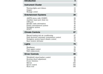
- 2015 Ford FLEX Owners Manuals
- Ford FLEX Owners Manuals
- 2014 Ford FLEX Owners Manuals
- Ford FLEX Owners Manuals
- 2013 Ford FLEX Owners Manuals
- Ford FLEX Owners Manuals
- 2010 Ford FLEX Owners Manuals
- Ford FLEX Owners Manuals
- 2009 Ford FLEX Owners Manuals
- Ford FLEX Owners Manuals
- 2011 Ford FLEX Owners Manuals
- Ford FLEX Owners Manuals
- 2012 Ford FLEX Owners Manuals
- Ford FLEX Owners Manuals
- Download PDF Manual
-
WARNING: The dipstick cap and surrounding components may be hot; gloves are recommended.
1. Drive the vehicle 20 miles (30 km) or until it reaches normal operating temperature. 2. Park the vehicle on a level surface and engage the parking brake. 3. With the parking brake engaged and your foot on the brake pedal, start the engine and move the gearshift lever through all of the gear ranges. Allow a minimum of 10 seconds for each gear to engage. 4. Latch the gearshift lever in P (Park) and leave the engine running. 5. Remove the dipstick, wiping it clean with a clean, dry lint free rag. If necessary, refer to Identifying components in the engine compartment in this chapter for the location of the dipstick. (For vehicles with the EcoBoost™ engine, move the air filter assembly aside to access the transmission dipstick).
WARNING: Use gloves when moving the air filter assembly; components will be hot.
For vehicles equipped with the EcoBoost™ engine, do the following: A. Shut the engine off. 374
2010 Flex (471) Owners Guide, 2nd Printing USA (fus)
Maintenance and Specifications
B. Clean the area around the clamp that connects the air filter assembly to the rubber hose (1).
C. Remove the bolt cover (if equipped).
D. Remove two bolts that attach the air filter assembly to the front of the vehicle (2). E. Loosen the clamp holding the air filter assembly to the rubber hose (1). F. Remove the harness retaining clip by pulling up (3). Do not disconnect the mass airflow sensor (4). G. Without disconnecting the mass airflow sensor (4), pull the air filter assembly up to disconnect the air filter assembly from the seated grommets located underneath the air filter assembly.
375
2010 Flex (471) Owners Guide, 2nd Printing USA (fus)
Maintenance and Specifications
H. Rotate the air filter assembly 90
degrees counterclockwise and reinstall into the rubber hose.I. Tighten the clamp (1). J. The transmission fluid level indicator can now be accessed.
WARNING: Do not run engine with the air filter disconnected.
Start the engine and continue with Step 6. 6. Install the dipstick making sure it is fully seated in the filler tube by turning it to the locked position. 7. Remove the dipstick and inspect the fluid level. The fluid should be in the designated areas for normal operating temperature. Low fluid level If the fluid level is below the MIN range of the dipstick, add fluid to reach the hash mark level. Note: If the fluid level is below the MIN level, do not drive the vehicle. An underfill condition may cause shift and/or engagement concerns and/or possible damage. Correct fluid level The transmission fluid should be checked at normal operating temperature 180°F-200°F (82°C-93°C) on a level surface. The normal operating temperature can be reached after approximately 20 miles (30 km) of driving.
MAX
MIN
376
2010 Flex (471) Owners Guide, 2nd Printing USA (fus)
Maintenance and Specifications
MIN
MAX
The transmission fluid level should be targeted within the cross-hatch area if at normal operating temperature 180°F-200°F (82°C-93°C). High fluid level If the fluid level is above the MAX range of the dipstick, remove fluid to reach the hashmark level. Note: Fluid level above the MAX level may cause shift and/or engagement concerns and/or possible damage. High fluid levels can be caused by an overheating condition. If your vehicle has been operated for an extended period at high speeds, in city traffic during hot weather or pulling a trailer, the vehicle should be turned off until normal operating temperatures are reached. Depending on vehicle use, cooling times could take up to 30 minutes or longer. Adjusting automatic transmission fluid levels Before adding any fluid, make sure the correct type is used. The type of fluid used is normally indicated on the dipstick and also in the Maintenance product specifications and capacities section in this chapter. Use of a non-approved automatic transmission fluid may cause internal transmission component damage. If necessary, add fluid in 1/2 pint (250 ml) increments through the filler tube until the level is correct.
MIN
MAX
If an overfill occurs, excess fluid should be removed by an authorized dealer. An overfill condition of transmission fluid may cause shift and/or engagement concerns and/or possible damage. Do not use supplemental transmission fluid additives, treatments or cleaning agents. The use of these materials may affect transmission operation and result in damage to internal transmission components.
377
2010 Flex (471) Owners Guide, 2nd Printing USA (fus)
Maintenance and Specifications
For vehicles equipped with the EcoBoost engine, reinstall the air filter assembly. After the fluid level has been checked and adjusted as necessary, do the following: A. Shut the engine off. B. Loosen the clamp holding the air filter assembly to the rubber hose. C. Rotate the air filter assembly 90 degrees clockwise without disconnecting the mass air flow sensor. D. Seat the air filter assembly back into the grommets by pushing down on the air filter assembly. E. Tighten the clamp. F. Install and tighten two bolts that attach air filter assembly to the front of the vehicle. G. Install the bolt cover (if equipped). H. Reinstall the harness retaining clip into the front of the air filter assembly.
AIR FILTER Refer to scheduled maintenance information for the appropriate intervals for changing the air filter element. When changing the air filter element, use only the air filter element listed. Refer to Motorcraft威 part numbers in this chapter.
WARNING: To reduce the risk of vehicle damage and/or personal burn injuries do not start your engine with the air
cleaner removed and do not remove it while the engine is running.
For Ecoboost™ equipped vehicles, when servicing the air cleaner, it is important that no foreign material enter the air induction system. The engine and turbocharger are susceptible to damage from even small particles.
378
2010 Flex (471) Owners Guide, 2nd Printing USA (fus)
Maintenance and Specifications
Changing the air filter element 3.5L V6 engine
3.5L V6 EcoBoost engine
1. Release the clamps that secure the air filter housing cover. 2. Carefully separate the two halves of the air filter housing. 3. Remove the air filter element from the air filter housing. 4. Wipe the air filter housing and cover clean to remove any dirt or debris and to ensure good sealing. 5. Install a new air filter element. Be careful not to crimp the filter element edges between the air filter housing and cover. This could cause filter damage and allow unfiltered air to enter the engine if not properly seated.
379
2010 Flex (471) Owners Guide, 2nd Printing USA (fus)
Maintenance and Specifications
6. Replace the air filter housing cover and secure the clamps. Be sure that the air cleaner cover tabs are engaged into the slots of the air cleaner housing.
Note: Failure to use the correct air filter element may result in severe engine damage. The customer warranty may be void for any damage to the engine if the correct air filter element is not used.
MOTORCRAFT PART NUMBERS Component
3.5L V6 engine
3.5L V6 EcoBoost engine FA-1884
FA-1884
BXT-65-750
FL-500-S SP-4111Engine air filter element Battery Oil filter Spark Plugs 1For spark plug replacement, see your authorized dealer. Refer to scheduled maintenance information for the appropriate intervals for changing the spark plugs. Replace the spark plugs with ones that meet Ford material and design specifications for your vehicle, such as Motorcraft威 or equivalent replacement parts. The customer warranty may be void for any damage to the engine if such spark plugs are not used.
BXT-65-750
FL-500-S SP-5121380
2010 Flex (471) Owners Guide, 2nd Printing USA (fus)
/
威
Maintenance and Specifications
威
—
—
威
威
威
威
威
381
2010 Flex (471) Owners Guide, 2nd Printing USA (fus)
Maintenance and Specifications
•
•
•
•
威 •
威 •
威 •
•
•
•
•
威 •
威 •
威 •
382
威 •
2010 Flex (471) Owners Guide, 2nd Printing USA (fus)
Maintenance and Specifications
—
—
威
威
威
威