- 2015 Ford Escape Owners Manuals
- Ford Escape Owners Manuals
- 2009 Ford Escape Owners Manuals
- Ford Escape Owners Manuals
- 2010 Ford Escape Owners Manuals
- Ford Escape Owners Manuals
- 2004 Ford Escape Owners Manuals
- Ford Escape Owners Manuals
- 2006 Ford Escape Owners Manuals
- Ford Escape Owners Manuals
- 2011 Ford Escape Owners Manuals
- Ford Escape Owners Manuals
- 2007 Ford Escape Owners Manuals
- Ford Escape Owners Manuals
- 2003 Ford Escape Owners Manuals
- Ford Escape Owners Manuals
- 2016 Ford Escape Owners Manuals
- Ford Escape Owners Manuals
- 2001 Ford Escape Owners Manuals
- Ford Escape Owners Manuals
- 2013 Ford Escape Owners Manuals
- Ford Escape Owners Manuals
- 2014 Ford Escape Owners Manuals
- Ford Escape Owners Manuals
- 2012 Ford Escape Owners Manuals
- Ford Escape Owners Manuals
- 2002 Ford Escape Owners Manuals
- Ford Escape Owners Manuals
- Download PDF Manual
-
fuel. If you cannot find unleaded fuel or can only get fuel with an anti-knock index lower than is recommended for your vehicle, contact a regional office or owner relations/customer relationship office. The use of leaded fuel in your vehicle without proper conversion may damage the effectiveness of your emission control system and may cause engine knocking or serious engine damage. Ford Motor Company/Ford of Canada is not responsible for any damage caused by use of improper fuel. Using leaded fuel may also result in difficulty importing your vehicle back into the U.S.
If your vehicle must be serviced while you are traveling or living in Asia-Pacific Region, Sub-Saharan Africa, U.S. Virgin Islands, Central America, the Caribbean, and Israel, contact the nearest authorized dealer. If the authorized dealer cannot help you, contact: FORD MOTOR COMPANY FORD EXPORT OPERATIONS & GLOBAL INITIATIVES 1555 Fairlane Drive Fairlane Business Park #3
Allen Park, Michigan 48101
U.S.A. Telephone: (313) 594-4857
For customers in Guam, the Commonwealth of the Northern Mariana Islands (CNMI), America Samoa, and the U.S. Virgin Islands, please feel free to call our Toll-Free Number: (800) 841-FORD (3673). FAX: (313) 390-0804
Email: [email protected] If your vehicle must be serviced while you are traveling or living in Puerto Rico, contact the nearest authorized dealer. If the authorized dealer cannot help you, contact: Ford International Business Development Inc. Customer Relationship Center P.O. Box 11957
Caparra Heights Station San Juan, Puerto Rico 00922-1957
Telephone: (800) 841-FORD (3673) FAX: (313) 390-0804
Email: [email protected] www.ford.com.pr If your vehicle must be serviced while you are traveling or living in the Middle East, contact the nearest authorized dealer. If the authorized dealer cannot help you, contact:206
Escape (TM2)
Customer Assistance
Ford Middle East Customer Relationship Center P.O. Box 21470
Dubai, United Arab Emirates Telephone: +971 4 3326084
Toll-Free Number for the Kingdom of Saudi Arabia: 800 8971409
Local Telephone Number for Kuwait: 24810575
FAX: +971 4 3327299
Email: [email protected] www.me.ford.com If you buy your vehicle in North America and then relocate to any of the above locations, register your vehicle identification number (VIN) and new address with Ford Motor Company Export Operations & Global Growth Initiatives by emailing [email protected]. If you are in another foreign country, contact the nearest authorized dealer. If the authorized dealer employees cannot help you, they can direct you to the nearest Ford affiliate office. Customers in the U.S. should call 1-800-392-3673. ORDERING ADDITIONAL OWNER'S LITERATURE To order the publications in this portfolio, contact Helm, Incorporated at: HELM, INCORPORATED 47911 Halyard Drive Plymouth, Michigan 48170
Attention: Customer Service Or to order a free publication catalog, call toll free: 1-800-782-4356
Monday-Friday 8:00 a.m. - 6:00 p.m. EST Helm, Incorporated can also be reached by their website: www.helminc.com(Items in this catalog may be purchased by credit card, check or money order.) Obtaining a French Owner’s Manual French Owner’s Manual can be obtained from your authorized dealer or by contacting Helm, Incorporated using the contact information listed previously in this section. REPORTING SAFETY DEFECTS (U.S. ONLY)
(cid:40)(cid:20)(cid:23)(cid:21)(cid:24)(cid:24)(cid:26)
If you believe that your vehicle has a defect which could cause a crash or could cause injury or death, you should immediately inform the National Highway Traffic Safety Administration (NHTSA) in addition to notifying Ford Motor Company. If NHTSA receives similar complaints, it may open an investigation, and if it finds that a safety defect exists in a group of vehicles, it may order a recall and remedy campaign. However, NHTSA cannot become involved in individual problems between you, your dealer, or Ford Motor Company.
207
Escape (TM2)
Customer Assistance
To contact NHTSA, you may call the Vehicle Safety Hotline toll-free at 1-888-327-4236 (TTY: 1-800-424-9153); go to http://www.safercar.gov; or write to: Administrator 1200 New Jersey Avenue, Southeast Washington, D.C. 20590
You can also obtain other information about motor vehicle safety from http://www.safercar.gov. REPORTING SAFETY DEFECTS (CANADA ONLY) If you believe that your vehicle has a defect which could cause a crash or could cause injury or death, you should immediately inform Transport Canada.
Transport Canada Contact Information
Website Phone
https://wwwapps.tc.gc.ca/Saf-Sec-Sur/7/PCDB-BDPP/Index.aspx 1–800–333–0510
208
Escape (TM2)
Fuses
CHANGING A FUSE Fuses
WARNING
Always replace a fuse with one that has the specified amperage rating. Using a fuse with a higher amperage rating can cause severe wire damage and could start a fire.
(cid:40)(cid:20)(cid:23)(cid:21)(cid:23)(cid:22)(cid:19) If electrical components in the vehicle are not working, a fuse may have blown. Blown fuses are identified by a broken wire within the fuse. Check the appropriate fuses before replacing any electrical components.
Standard Fuse Amperage Rating and Color
Color
Fuse rating
Mini fuses
2A 3A 4A 5A 7.5A 10A 15A 20A 25A 30A 40A 50A 60A 70A 80A
Grey Violet Pink Tan Brown Red Blue Yellow Natural Green
Standard
fuses Grey Violet Pink Tan Brown Red Blue Yellow Natural Green
Maxi fuses
Cartridge maxi fuses
Fuse link cartridge
Yellow
Green Orange
Red Blue Tan
Natural
Blue
Natural
Pink Green Red Yellow
Black
Blue
Natural
Pink Green Red Yellow Brown Black
209
Escape (TM2)
Fuses
FUSE SPECIFICATION CHART Pre-Fuse Box Your vehicle is equipped with a pre-fuse box located in the engine compartment attached to the positive battery post. This box contains several high current fuses. If replacement of these high current fuses is required, see your authorized dealer. Power Distribution Box WARNINGS
Always disconnect the battery before servicing high current fuses.
WARNINGS
To reduce risk of electrical shock, always replace the cover to the power distribution box before
reconnecting the battery or refilling fluid reservoirs.
The power distribution box is located in the engine compartment. It has high-current fuses that protect your vehicle's main electrical systems from overloads. If the battery has been disconnected and reconnected, some features will need to be reset. See Changing the 12V Battery (page 229).
(cid:40)(cid:20)(cid:24)(cid:26)(cid:22)(cid:27)(cid:28)
Lift the release lever at the rear of the cover to remove it.
The high-current fuses are coded as follows:
210
Escape (TM2)
Fuses
Fuse or relay number
Fuse amp rating
Protected components
F7
F8
F9
F10
F11
F12
F13
F14F15
F16F17
F18
F19F20
F21
F22
F23
F24
F25F26
F27
F28
F2940A**
30A**
40A**
30A** 30A** 25A**
20A** 25A**
20A** 20A** 5A*
15A* 5A* 15A* 5A* 5A* 10A*
5A* 15A* 10A* 25A*
Anti-lock brake system and electronic stability program pump Electronic stability program valve Not used Heater blower motor Not used Powertrain control module relay fuse Starter relay Rear power window (without door control unit) Front cigar lighter or power outlet Front power window (without door control unit) Rear power outlet Center power outlet Anti-lock brake system and electronic stability program 15 feed Horn Stop light switch Battery monitor system Relay coils Light switch module Power exterior mirror (without door control unit) Keep-alive power Air conditioner clutch Vehicle power - fuel injector Rear window defroster
211
Escape (TM2)
Fuses
Fuse or relay number
Fuse amp rating
Protected components
F30
F31F32
F33
F34
F35
F36
F37F38
F39
F40
F41
F42
F43
F44
F45
F46
F47
F48
R1
R2
R3R4
R55A*
15A* 10A* 10A* 15A* 5A* 10A*
5A*
5A*
5A* 20A* 15A* 15A* 15A*
50A**
5A*
Micro relay
Not used Power transfer unit oil cooling fan (Middle East specification) Vehicle power Vehicle power 2
Vehicle power 3
Vehicle power 4
Active grill shutters Occupant classification sensor, Passenger airbag deactivation indicator feed Engine control module and transmission control module ignition feed Daytime running lamps and headlamp control module ignition feed Electronic power assist steering 15 feed Body control module 15 feed Rear wiper Headlamp control module supply Front fog daytime running lamps Not used Smart wiper motor modules Not used Keypad Not used Horn Power transfer unit oil cooling fan (Middle East specification) Front fog daytime running lamps Not used212
Escape (TM2)
Fuses
Fuse or relay number
Fuse amp rating
Protected components
R6
R7
R8
R9
R10
R11
R12
R13
R14
R15
R16Mini relay
Mini relay Micro relay Power relay Mini relay Mini relay Power relay Power relay
Not used Not used Delayed accessory relay Not used Starter relay Air conditioner clutch Cooling fan Heater blower Engine control relay Heated rear window Ignition 15
*Mini fuses **Cartridge fuses
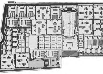
Passenger Compartment Fuse Panel The fuse panel is located on the right side below the glove box.
213
Escape (TM2)
Fuses
The fuses are coded as follows:
214
Escape (TM2)
Fuses
Fuse or relay number
Fuse amp rating
Protected components
56
57
58
59
6061
62
63
64
65
66
6768
69
70
7172
73
74
75
76
77
7820A
5A 10A
20A 5A 10A 20A 7.5A
5A 20A 10A
7.5A 5A 15A 15A 10A 20A 5A
Fuel pump supply, Air mass meter Not used Not used Passive anti-theft transceiver Interior light, Driver door switch pack, Glove box illumination, Overhead console switch bank Cigar lighter, Power point Rain sensor module, Auto-dimming mirror Not used Not used Liftgate release Driver door unlock supply, Double lock SYNC, Multifunction display, Global posi- tioning system module Not used Instrument cluster Central lock and unlock supply Heating control head (manual air condi- tioner), Dual electronic automatic temperature control Steering wheel module Data link connector High beam headlamp supply Fog lamp supply Reversing lamp supply Windshield washer supply Ignition switch, Start button
215
Escape (TM2)
Fuses
Fuse or relay number
Fuse amp rating
Protected components
79
80
81
82
83
84
85
8687
88
8915A
20A 5A 20A 20A 20A 7.5A 10A
Radio, Navigation DVD player, Touch screen, Hazard light switch, Door lock switch Moonroof supply Radio frequency receiver Windshield washer relay Central locking Drive door unlock supply, Double lock Electronic 15 feed Air bag module, Occupant classification system, Passenger air bag deactivation indicator Not used Not used Not used
Luggage Compartment Fuse Panel The fuse panel is located in the luggage compartment behind the passenger's side wheel well. Remove the fuse panel cover to gain access to the fuses.
(cid:40)(cid:20)(cid:21)(cid:28)(cid:28)(cid:21)(cid:26)
The fuses are coded as follows:
216
Escape (TM2)
Fuses
Fuse or relay number
Fuse amp rating
F1
F2
F3
F4
F5
F6
F7
F8
F9
F10
F11
F12
F13
F14
F15
F16
F17
F18
F19
F20
F21
F22
F23
F24
F25
F265A 10A 5A 25A 25A 25A 25A
25A 5A 5A
25A 30A 25A 40A
Protected components Hands-free liftgate entry module Keyless vehicle module Keyless vehicle door handles Door control unit front left Door control unit front right Door control unit rear left Door control unit rear right Not used Driver seat motor Driver seat memory module logic feed Rear ignition coil feed Not used Not used Not used Not used Not used Not used Not used Not used Not used Not used Not used Audio amplifier DC/AC power converter Power liftgate Accessories / Trailer tow module 30 feed
217
Escape (TM2)
Fuses
Fuse or relay number
Fuse amp rating
Protected components
F27
F28
F29F30
F31
F32
F33
F34
F35
F36
F37
F38
F39
F40
F41
F42
F43
F44
F45
F46
R1
R2
R3
R4
R5
R65A
5A 5A
20A 20A
5A
Power relay
Not used Not used Blind spot detection system, Rear view camera with park assist Parking aid module Not used DC/AC power converter Not used Driver seat heater Passenger seat heater Not used Moonroof Not used Not used Not used Not used Not used Not used Not used Not used Not used Rear 15 relay Not used Not used Not used Not used Not used
218
Escape (TM2)
Maintenance
Working with the Engine Off 1. Set the parking brake and shift to P
(Park).
2. Turn off the engine and remove the key
(if equipped).
3. Block the wheels. Working with the Engine On
WARNING
To reduce the risk of vehicle damage and/or personal burn injuries, do not start your engine with the air cleaner
removed and do not remove it while the engine is running.
1. Set the parking brake and shift to P
(Park).
2. Block the wheels OPENING AND CLOSING THE HOOD Opening the Hood
GENERAL INFORMATION Have your vehicle serviced regularly to help maintain its roadworthiness and resale value. There is a large network of Ford authorized dealers that are there to help you with their professional servicing expertise. We believe that their specially trained technicians are best qualified to service your vehicle properly and expertly. They are supported by a wide range of highly specialized tools developed specifically for servicing your vehicle. To help you service your vehicle, we provide scheduled maintenance information which makes tracking routine service easy. See Scheduled Maintenance (page ?). If your vehicle requires professional service, your authorized dealer can provide the necessary parts and service. Check your warranty information to find out which parts and services are covered. Use only recommended fuels, lubricants, fluids and service parts conforming to specifications. Motorcraft® parts are designed and built to provide the best performance in your vehicle. Precautions • Do not work on a hot engine. • Make sure that nothing gets caught in
moving parts.
• Do not work on a vehicle with the
engine running in an enclosed space, unless you are sure you have enough ventilation. Keep all open flames and other burning material (such as cigarettes) away from the battery and all fuel related parts.
•
(cid:40)(cid:20)(cid:23)(cid:21)(cid:23)(cid:24)(cid:26) 1. Pull the hood release handle.
219
Escape (TM2)
Maintenance
(cid:40)(cid:20)(cid:23)(cid:21)(cid:23)(cid:24)(cid:27) 2. Move the catch to the right.
(cid:40)(cid:27)(cid:26)(cid:26)(cid:27)(cid:25) 3. Open the hood and support it with the
prop rod.
Closing the Hood 1. Remove the prop rod from the catch
and secure properly after use.
2. Lower the hood and allow it to drop
from under its own weight for the last 8 - 11 inches (20 – 30 centimeters).
Note: Make sure that you have closed the hood properly.
220
Escape (TM2)
Maintenance
UNDER HOOD OVERVIEW - 1.6L ECOBOOST™
(cid:40)(cid:20)(cid:23)(cid:21)(cid:23)(cid:24)(cid:28)
Engine coolant reservoir Engine oil filler cap Brake fluid reservoir Battery Power distribution box Air filter assembly Engine oil dipstick Windshield washer fluid reservoir
221
Escape (TM2)
Maintenance
UNDER HOOD OVERVIEW - 2.0L ECOBOOST™
(cid:40)(cid:20)(cid:23)(cid:25)(cid:19)(cid:21)(cid:21)
Engine coolant reservoir Engine oil dipstick Brake fluid reservoir Battery Power distribution box Air filter assembly Engine oil filler cap Windshield washer fluid reservoir
222
Escape (TM2)
Maintenance
UNDER HOOD OVERVIEW - 2.5L
(cid:36)
(cid:38)(cid:37)
(cid:39)
(cid:40)
(cid:41)
(cid:42)
(cid:43)
(cid:40)(cid:20)(cid:23)(cid:25)(cid:19)(cid:21)(cid:22)
Windshield washer fluid reservoir Engine coolant reservoir Engine oil filler cap Engine oil dipstick Brake fluid reservoir Battery Power distribution box Air filter assembly
223
Escape (TM2)
Maintenance
ENGINE OIL DIPSTICK - 1.6L ECOBOOST™
(cid:40)(cid:20)(cid:23)(cid:25)(cid:19)(cid:21)(cid:19)
MIN MAX
ENGINE OIL DIPSTICK - 2.0L ECOBOOST™/2.5L
Note: Make sure that the level is between the MIN and the MAX marks. 1. Make sure that your vehicle is on level
ground.
2. Turn the engine off and wait 10 minutes
for the oil to drain into the oil pan.
3. Remove the dipstick and wipe it with
a clean, lint-free cloth. Replace the dipstick and remove it again to check the oil level.
If the level is at the MIN mark, add oil immediately. Adding Engine Oil Note: Do not remove the filler cap when the engine is running. Note: Do not add oil further than the MAX mark. Oil levels above the MAX mark may cause engine damage.
(cid:40)(cid:20)(cid:23)(cid:21)(cid:26)(cid:22)(cid:21) Only use oils certified for gasoline engines by the American Petroleum Institute (API). An oil with this trademark symbol conforms to the current engine and emission system protection standards and fuel economy requirements of the International Lubricants Specification Advisory Council (ILSAC), comprised of U.S. and Japanese automobile manufacturers.
(cid:40)(cid:20)(cid:23)(cid:21)(cid:23)(cid:25)(cid:21)
MIN MAX
ENGINE OIL CHECK Note: Check the level before starting the engine.
224
Escape (TM2)
Maintenance
Note: Make sure that the level is between the MIN and MAX marks on the coolant reservoir. Note: Coolant expands when it is hot. The level may extend beyond the MAX mark Note: If the level is at the MIN mark, below the MIN mark, or empty, add coolant immediately. See Adding Engine Coolant in this chapter. The coolant concentration should be maintained within 48% to 50%, which equates to a freeze point between -30 F degrees (-34 C) and -34 F (-37 C). Note: For best results, coolant concentration should be tested with a refractometer such as Rotunda tool 300-ROB75240 available from your authorized dealer. Ford does not recommend the use of hydrometers or coolant test strips for measuring coolant concentrations. Note: Automotive fluids are not interchangeable. Do not use engine coolant or antifreeze or windshield washer fluid outside of its specified function and vehicle location. Adding Engine Coolant WARNINGS
Do not add engine coolant when the engine is hot. Steam and scalding liquids released from a hot cooling system can burn you badly. Also, you can be burned if you spill coolant on hot engine parts.
Do not put engine coolant in the windshield washer fluid container. If sprayed on the windshield, engine
coolant could make it difficult to see through the windshield.
1. Remove the filler cap. 2. Add engine oil that meets the Ford specifications. See Capacities and Specifications (page ?).
3. Replace the filler cap. Turn it until you
feel a strong resistance.
Resetting the Oil Life Monitoring System Note: Reset the oil life monitoring only after an oil change. 1. Turn the ignition key to the on position.
Do not start the engine. For vehicles with push-button start, press and hold the start button for two seconds without pressing the brake pedal. Do not attempt to start the engine.
2. Press both the accelerator and brake
pedals at the same time.
3. Keep both pedals fully pressed. 4. After three seconds, the Service: Oil
reset in prog. message will be displayed.
5. After 25 seconds, the Service: Oil reset complete message will be displayed. 6. Release both the accelerator and brake
pedals.
7. The Service: Oil reset complete
message will no longer be displayed. 8. Rotate the key to the off position. For vehicles with push-button start, press the start button to turn the vehicle off completely.
ENGINE COOLANT CHECK Checking the Engine Coolant When the engine is cold, check the concentration and level of the engine coolant at the intervals listed in the scheduled maintenance information. See Scheduled Maintenance (page 400).
225
Escape (TM2)
Maintenance
WARNINGS
To reduce the risk of personal injury, make sure the engine is cool before unscrewing the coolant pressure relief cap. The cooling system is under pressure; steam and hot liquid can come out forcefully when the cap is loosened slightly.
Do not add coolant further than the MAX mark.
Note: Do not use stop leak pellets, cooling system sealants, or additives as they can cause damage to the engine cooling or heating systems. This damage would not be covered under your vehicle’s warranty. Note: During normal vehicle operation, the engine coolant may change color from orange to pink or light red. As long as the engine coolant is clear and uncontaminated, this color change does not indicate the engine coolant has degraded nor does it require the engine coolant to be drained, the system to be flushed, or the engine coolant to be replaced.
• Do not mix different colors or types of coolant in your vehicle. Make sure the correct coolant is used. Mixing of engine coolants may harm your engine’s cooling system. The use of an improper coolant may harm engine and cooling system components and may void the warranty. Use prediluted engine coolant meeting the Ford specification. See Capacities and Specifications (page ?). In case of emergency, a large amount of water without engine coolant may be added in order to reach a vehicle service location. In this instance, the cooling system must be drained, chemically cleaned with Motorcraft® Premium Cooling System Flush, and refilled with prediluted engine coolant as soon as possible. Water alone (without engine coolant) can cause engine damage from corrosion, overheating or freezing.
•
• Do not use alcohol, methanol, brine or any engine coolants mixed with alcohol or methanol antifreeze (coolant). Alcohol and other liquids can cause engine damage from overheating or freezing.
• Do not add extra inhibitors or additives to the coolant. These can be harmful and compromise the corrosion protection of the engine coolant.
Unscrew the cap slowly. Any pressure will escape as you unscrew the cap. Add prediluted engine coolant meeting the Ford specification. See Capacities and Specifications (page ?). Whenever coolant has been added, the coolant level in the coolant reservoir should be checked the next few times you drive the vehicle. If necessary, add enough prediluted engine coolant to bring the coolant level to the proper level.
226
Escape (TM2)
Maintenance
Recycled Engine Coolant Ford Motor Company does not recommend the use of recycled engine coolant since a Ford-approved recycling process is not yet available. Always dispose of used automotive fluids in a responsible manner. Follow your community’s regulations and standards for recycling and disposing of automotive fluids. Severe Climates If you drive in extremely cold climates: • It may be necessary to have a Ford authorized dealer increase the coolant concentration above 50%.
• A coolant concentration of 60% will
provide improved freeze point protection. Engine coolant concentrations above 60% will decrease the overheat protection characteristics of the engine coolant and may cause engine damage
If you drive in extremely hot climates: It may be necessary to have a Ford • authorized dealer decrease the coolant concentration to 40%.
• A coolant concentration of 40% will
provide improved overheat protection. Engine coolant concentrations below 40% will decrease the corrosion/freeze protection characteristics of the engine coolant and may cause engine damage.
Vehicles driven year-round in non-extreme climates should use prediluted engine coolant for optimum cooling system and engine protection.
What you Should Know About Fail- Safe Cooling If the engine coolant supply is depleted, this feature allows the vehicle to be driven temporarily before incremental component damage is incurred. The “fail-safe” distance depends on ambient temperatures, vehicle load and terrain. How Fail-Safe Cooling Works If the engine begins to overheat, the engine coolant temperature gauge will move to the red (hot) area and:
A high engine temperature message will appear in the information display. The service engine soon indicator will illuminate. If the engine reaches a preset over-temperature condition, the engine will automatically switch to alternating cylinder operation. Each disabled cylinder acts as an air pump and cools the engine. When this occurs the vehicle will still operate. However: • •
The engine power will be limited. The air conditioning system will be disabled.
Continued operation will increase the engine temperature and the engine will completely shut down, causing steering and braking effort to increase. Once the engine temperature cools, the engine can be re-started. Take your vehicle to an authorized dealer as soon as possible to minimize engine damage.
227
Escape (TM2)
Maintenance
AUTOMATIC TRANSMISSION FLUID CHECK Note: Transmission fluid should be checked by an authorized dealer. If required, fluid should be added by an authorized dealer. The automatic transmission does not have a transmission fluid dipstick. Have an authorized dealer check and change the transmission fluid and filter at the correct service interval. See Scheduled Maintenance (page 400). Your transmission does not consume fluid. However, the fluid level should be checked if the transmission is not working properly, (i.e., if the transmission slips or shifts slowly) or if you notice some sign of fluid leakage. Do not use supplemental transmission fluid additives, treatments or cleaning agents. The use of these materials may affect transmission operation and result in damage to internal transmission components. BRAKE FLUID CHECK Fluid levels between the MIN and MAX lines are within the normal operating range; there is no need to add fluid. If the fluid levels are outside of the normal operating range, the performance of the system could be compromised; seek service from your authorized dealer immediately. POWER STEERING FLUID CHECK Your vehicle is equipped with an electric power steering (EPS) system. There is no fluid reservoir to check or fill.
When Fail-Safe Mode Is Activated
WARNINGS
Fail-safe mode is for use during emergencies only. Operate the vehicle in fail-safe mode only as long as necessary to bring the vehicle to rest in a safe location and seek immediate repairs. When in fail-safe mode, the vehicle will have limited power, will not be able to maintain high-speed operation, and may completely shut down without warning, potentially losing engine power, power steering assist, and power brake assist, which may increase the possibility of a crash resulting in serious injury.
Never remove the coolant reservoir cap while the engine is running or hot.
You have limited engine power when in the fail-safe mode, so drive the vehicle with caution. The vehicle will not be able to maintain high-speed operation and the engine will run rough. Remember that the engine is capable of completely shutting down automatically to prevent engine damage, therefore: 1. Pull off the road as soon as safely possible and turn off the engine.
2. Arrange for the vehicle to be taken to
3.
an authorized dealer. If this is not possible, wait a short period for the engine to cool.
4. Check the coolant level and replenish
if low.
5. Re-start the engine and take your
vehicle to an authorized dealer.
Note: Driving the vehicle without repairing the engine problem increases the chance of engine damage. Take your vehicle to an authorized dealer as soon as possible.
228
Escape (TM2)
Maintenance
CHANGING THE 12V BATTERY
WARNINGS
Batteries normally produce explosive gases which can cause personal injury. Therefore, do not allow
flames, sparks or lighted substances to come near the battery. When working near the battery, always shield your face and protect your eyes. Always provide proper ventilation.
When lifting a plastic-cased battery, excessive pressure on the end walls could cause acid to flow through the vent caps, resulting in personal injury and damage to the vehicle or battery. Lift the battery with a battery carrier or with your hands on opposite corners.
Keep batteries out of reach of children. Batteries contain sulfuric acid. Avoid contact with skin, eyes or
clothing. Shield your eyes when working near the battery to protect against possible splashing of acid solution. In case of acid contact with skin or eyes, flush immediately with water for a minimum of 15 minutes and get prompt medical attention. If acid is swallowed, call a physician immediately.
Your vehicle is equipped with a Motorcraft® maintenance-free battery which normally does not require additional water during its life of service. Note: If your battery has a cover/shield, make sure it is reinstalled after the battery has been cleaned or replaced. Note: See an authorized dealer for low voltage battery access, testing, or replacement.
FUEL FILTER Your vehicle is equipped with a lifetime fuel filter that is integrated with the fuel tank. Regular maintenance or replacement is not needed. WASHER FLUID CHECK
WARNING
If you operate your vehicle in temperatures below 40°F (5°C), use washer fluid with antifreeze
protection. Failure to use washer fluid with antifreeze protection in cold weather could result in impaired windshield vision and increase the risk of injury or accident.
Note: The front and rear washer systems are supplied from the same reservoir. Add fluid to fill the reservoir if the level is low. Only use a washer fluid that meets Ford specifications. See Capacities and Specifications (page 273). State or local regulations on volatile organic compounds may restrict the use of methanol, a common windshield washer antifreeze additive. Washer fluids containing non-methanol antifreeze agents should be used only if they provide cold weather protection without damaging the vehicle’s paint finish, wiper blades or washer system.
229
Escape (TM2)
Maintenance
presets, are also maintained in memory by power from the low voltage battery. When a technician disconnects and connects the low voltage battery, these settings are erased. Complete the following procedure in order to restore the settings: 1. With the vehicle at a complete stop,
set the parking brake.
2. Shift the transmission into P. 3. Turn off all accessories. 4. Step on the brake pedal and start the
vehicle.
5. Run the engine until it reaches normal
operating temperature. While the engine is warming up, complete the following: Reset the clock. See Audio System (page 98). Reset the power windows bounce-back feature. See Windows and Mirrors (page ?). Reset the radio station presets. See Audio System (page 98).
6. Allow the engine to idle for at least one minute. If the engine turns off, step on the accelerator to start the engine.
7. While the engine is running, step on the brake pedal and shift the transmission to N.
8. Allow the engine to run for at least one minute by pressing on the accelerator pedal.
9. Drive the vehicle at least 10 miles (16
kilometers) to completely relearn the idle and fuel trim strategy.Note: If you do not allow the engine to relearn the idle and fuel trim strategy, the idle quality of your vehicle may be adversely affected until the engine computer eventually relearns the idle trim and fuel trim strategy.
When a low voltage battery replacement is necessary, see an authorized dealer to replace the low voltage battery with a Ford recommended replacement low voltage battery that matches the electrical requirements of the vehicle To ensure proper operation of the battery management system (BMS), do not allow a technician to connect any electrical device ground connection directly to the low voltage battery negative post. A connection at the low voltage battery negative post can cause inaccurate measurements of the battery condition and potential incorrect system operation. Note: Note: If a person adds electrical or electronic accessories or components to the vehicle, the accessories or components may adversely affect the low voltage battery performance and durability and may also affect the performance of other electrical systems in the vehicle. For longer, trouble-free operation, keep the top of the battery clean and dry. Also, make certain the battery cables are always tightly fastened to the battery terminals. If you see any corrosion on the battery or terminals, remove the cables from the terminals and clean with a wire brush. You can neutralize the acid with a solution of baking soda and water. When a battery replacement is required, the battery should only be replaced with a Ford recommended replacement battery that matches the electrical requirements of the vehicle. Because your vehicle’s engine is electronically-controlled by a computer, some engine control settings are maintained by power from the low voltage battery. Some engine computer settings, like the idle trim and fuel trim strategy, optimize the driveability and performance of the engine. Some other computer settings, like the clock and radio station
230
Escape (TM2)
Maintenance
Note: Always dispose of automotive batteries in a responsible manner. Follow your local authorized standards for disposal. Call your local authorized recycling center to find out more about recycling automotive batteries. Note: It is recommended that the negative battery cable terminal be disconnected from the battery if you plan to store your vehicle for an extended period of time. CHECKING THE WIPER BLADES
(cid:40)(cid:20)(cid:23)(cid:21)(cid:23)(cid:25)(cid:22) Run the tip of your fingers over the edge of the blade to check for roughness. Clean the wiper blades with washer fluid or water applied with a soft sponge or cloth. CHANGING THE WIPER BLADES The wiper arms can be manually moved when the ignition is off. This allows for ease of blade replacement and cleaning under the blades. 1. Pull the wiper blade and arm away
from the glass.
Escape (TM2)
(cid:20)
(cid:20)
(cid:21)
Install in the reverse order.
(cid:40)(cid:20)(cid:21)(cid:28)(cid:28)(cid:28)(cid:19) 2. Press the locking buttons together. 3. Rotate and remove the wiper blade. 4. Note: Make sure that the wiper blade locks into place. Lower the wiper arm and blade back to the windshield. The wiper arms will automatically return to their normal position when the ignition is turned on. To change the rear blades, do the following: 1. Lift the wiper arm.
(cid:22)
(cid:21)
(cid:40)(cid:20)(cid:22)(cid:19)(cid:19)(cid:25)(cid:19) 2. Slightly rotate the wiper blade from the
wiper arm.
3. Disengage the wiper blade from the
wiper arm.
4. Remove the wiper blade.
231
Maintenance
Install in the reverse order.
5. Note: Make sure that the wiper blade locks into place. Replace wiper blades at least once per year for optimum performance. Poor wiper quality can be improved by cleaning the wiper blades and the windshield. CHANGING THE ENGINE AIR FILTER
WARNING
To reduce the risk of vehicle damage and/or personal burn injuries do not start your engine with the air cleaner
removed and do not remove it while the engine is running.
When changing the air filter element, use only the air filter element listed. See Capacities and Specifications (page 273). For EcoBoost equipped vehicles: When servicing the air cleaner, it is important that no foreign material enter the air induction system. The engine and turbocharger are susceptible to damage from even small particles. Change the air filter element at the proper interval. See Scheduled Maintenance (page 400). Note: Failure to use the correct air filter element may result in severe engine damage. The customer warranty may be void for any damage to the engine if the correct air filter element is not used.
1.6L and 2.0L EcoBoost Engines
(cid:40)(cid:20)(cid:23)(cid:21)(cid:26)(cid:20)(cid:19)
2.5L Engine
(cid:40)(cid:20)(cid:23)(cid:21)(cid:26)(cid:20)(cid:20) 1. Loosen the screws on the air tube clamp that fasten it to the air filter assembly tray.
2. Separate the clean air tube from the
air cleaner.
3. Remove the air cleaner from the
vehicle.
4. 5. Carefully separate the two halves of
the air filter housing. •
For 2.5L engines, disengage the clips that secure the air filter housing cover. For 1.6L and 2.0L engines, remove the screws securing the air filter housing cover.
•
6. Remove the air filter element from the
air filter housing.
232
Escape (TM2)
Maintenance
25 feet (7.6 meters) Horizontal reference line
Vehicles With Halogen Headlamps 1. Park the vehicle directly in front of a
wall or screen on a level surface, approximately 25 feet (7.6 meters) away.
2. Measure the height of the headlamp
bulb center from the ground and mark an 8 foot (2.4 meter) horizontal reference line on the vertical wall or screen at this height.
Note: To see a clearer light pattern for adjusting, you may want to block the light from one headlamp while adjusting the other. 3. Turn on the low beam headlamps to
illuminate the wall or screen and open the hood.
(cid:40)(cid:20)(cid:23)(cid:21)(cid:23)(cid:25)(cid:24) 4. On the wall or screen you will observe
a flat zone of high intensity light located at the top of the right hand portion of the beam pattern. If the top edge of the high intensity light zone is not at the horizontal reference line, the headlamp will need to be adjusted.
7. Wipe any dirt or debris from the air filter housing and cover to make sure no dirt gets in the engine and to make sure you have a good seal.
8. Slide the open end of the air filter
element in first, below the tab. Then push the closed end cap into the bottom of the tray. The closed end cap should fit inside the groove in the tray. The tab at the end of the closed end cap should be oriented down and fit between the forks on the tray.
9. Replace the air filter housing cover and
secure the clips.
10. Reinstall the air cleaner assembly into
the vehicle.
11. Reinstall the clean air tube assembly
into the air cleaner assembly.
12. Tighten the air tube fastening screws. ADJUSTING THE HEADLAMPS Vertical Aim Adjustment The headlamps on your vehicle are properly aimed at the assembly plant. If your vehicle has been in an accident, the alignment of your headlamps should be checked by your authorized dealer.
(cid:40)(cid:20)(cid:23)(cid:21)(cid:24)(cid:28)(cid:21)
8 feet (2.4 meters) Center height of lamp to ground
233
Escape (TM2)
Maintenance
(cid:40)(cid:20)(cid:23)(cid:21)(cid:23)(cid:25)(cid:26) 5. Locate the vertical adjuster on each
headlamp. Using a Phillips #2
screwdriver, turn the adjuster either clockwise or counterclockwise in order to aim the headlamp. The horizontal edge of the brighter light should touch the horizontal reference line.6. Close the hood and turn off the lamps. Vehicles With High Intensity Discharge Headlamps 1. Park the vehicle directly in front of a
wall or screen on a level surface, approximately 25 feet (7.6 meters) away.
2. Measure the height of the headlamp
bulb center from the ground and mark an 8 foot (2.4 meter) horizontal reference line on the vertical wall or screen at this height.
Note: To see a clearer light pattern for adjusting, you may want to block the light from one headlamp while adjusting the other. 3. Turn on the low beam headlamps to
illuminate the wall or screen and open the hood.
(cid:40)(cid:20)(cid:23)(cid:21)(cid:23)(cid:25)(cid:25) 4. There is a distinct cut-off (change from light to dark) in the left portion of the beam pattern. The top edge of this cut-off should be positioned two inches (5 centimeters) below the horizontal reference line.
(cid:40)(cid:20)(cid:23)(cid:21)(cid:23)(cid:25)(cid:26) 5. Locate the vertical adjuster on each
headlamp. Using a Phillips #2
screwdriver, turn the adjuster either clockwise or counterclockwise in order to aim the headlamp.6. Close the hood and turn off the lamps. Horizontal Aim Adjustment Horizontal aim is not required for this vehicle and is non-adjustable.
234
Escape (TM2)
Maintenance
Examples of acceptable condensation are: • Presence of thin mist (no streaks, drip
marks or droplets). Fine mist covers less than 50% of the lens.
Examples of unacceptable moisture (usually caused by a lamp water leak) are: • Water puddle inside the lamp. •
Large water droplets, drip marks or streaks present on the interior of the lens.
Take your vehicle to a dealer for service if any of the above conditions of unacceptable moisture are present. Replacing Headlamp Bulbs
WARNING
Handle a halogen headlamp bulb carefully and keep out of children’s reach. Grasp the bulb by only its
plastic base and do not touch the glass. The oil from your hand could cause the bulb to break the next time the headlamps are operated.
Note: If the bulb is accidentally touched, it should be cleaned with rubbing alcohol before being used.
REMOVING A HEADLAMP
•
(cid:40)(cid:20)(cid:23)(cid:21)(cid:23)(cid:25)(cid:27) 1. Make sure the headlamp control is in the off position and open the hood.
2. Remove the two screws from the
headlamp assembly.
3. Carefully pull the headlamp assembly as far as possible towards the front of the vehicle to disengage it from the lower fixing point.
4. Carefully lift the outer side of the
headlamp and remove it.
5. Disconnect the electrical connector. CHANGING A BULB Lamp Assembly Condensation Exterior lamps are vented to accommodate normal changes in pressure. Condensation can be a natural by-product of this design. When moist air enters the lamp assembly through the vents, there is a possibility that condensation can occur when the temperature is cold. When normal condensation occurs, a thin film of mist can form on the interior of the lens. The thin mist eventually clears and exits through the vents during normal operation. Clearing time may take as long as 48 hours under dry weather conditions.
235
Escape (TM2)
Maintenance
Headlamp:
(cid:40)(cid:20)(cid:23)(cid:21)(cid:23)(cid:26)(cid:20) 1. Remove the headlamp. 2. Remove service cap. 3. Disconnect the electrical connector. 4. Remove bulb from the headlamp
assembly by turning it counterclockwise, then pull it straight out.
Install the new bulbs in reverse order from the steps above. Be sure that the spring clip is not damaged or detached from the headlamp assembly during the replacement procedure. Replacing HID Headlamp Bulbs (If Equipped) The low beam headlamps on your vehicle use a high intensity discharge source. These lamps operate at a high voltage. When the bulb is burned out, the bulb and starter capsule assembly must be replaced by your authorized dealer.
(cid:40)(cid:20)(cid:23)(cid:21)(cid:23)(cid:25)(cid:28)
Side marker Low beam headlamp High beam headlamp
High beam headlamp:
(cid:40)(cid:20)(cid:23)(cid:21)(cid:23)(cid:26)(cid:19) 1. Remove the headlamp. 2. Remove service cap. 3. Disconnect the electrical connector. 4. Remove bulb from the headlamp
assembly by turning it counterclockwise, then pull it straight out.
Low beam headlamp:
236
Escape (TM2)
Maintenance
Replacing Side Marker Bulbs
(cid:40)(cid:20)(cid:23)(cid:21)(cid:23)(cid:26)(cid:21) 1. Remove the bulb socket from the headlamp assembly by turning it counterclockwise.
2. Remove the bulb by gently pull the
bulb straight out of the socket.
Install the new bulb in reverse order. Replacing Fog, Park and Turn Signal Bulbs
(cid:40)(cid:20)(cid:23)(cid:21)(cid:26)(cid:28)(cid:26)
Fog Lamp Park Lamp Turn Signal lamp
(cid:40)(cid:20)(cid:23)(cid:21)(cid:26)(cid:28)(cid:27) 1. Remove the screws from the splash
shield at the wheel well to gain access to the lamp assembly.
(cid:40)(cid:20)(cid:23)(cid:21)(cid:26)(cid:28)(cid:28) 2. Remove the bulb holder from the lamp
assembly by turning it counterclockwise.
3. Disconnect the electrical connector. 4. Remove the bulb from the bulb holder
by pulling it straight out.
Install the new bulbs in reverse order from the steps above.
237
Escape (TM2)
Maintenance
Replacing Tail, Brake and Turn Signal Bulbs
6. Remove the turn signal bulb or the tail
and brake bulb by turning the bulb socket counterclockwise. Gently pull the bulb straight out of the socket.
Install the new bulb in reverse order. Replacing Reverse Lamp Assembly For bulb replacement, see your authorized dealer. Replacing License Plate Lamp Bulb
(cid:22)
(cid:21)
(cid:20)
(cid:40)(cid:20)(cid:23)(cid:21)(cid:23)(cid:26)(cid:22) 1. Make sure the headlamp control is in the off position and open the liftgate.
2. Remove the two bolt covers using a
standard flat tip screwdriver.
3. Remove the two bolts from the lamp
assembly.
4. Gently pull the lamp assembly away
from the vehicle.
(cid:40)(cid:26)(cid:21)(cid:26)(cid:27)(cid:28) 1. Carefully release the spring clip. 2. Remove the lamp. 3. Remove the bulb. Reverse steps to reinstall bulb. Replacing High-Mount Brake Lamp Bulb Your vehicle is equipped with an LED center high-mount stop lamp located in the spoiler. It is designed to last the life of the vehicle. If replacement is required, see your authorized dealer.
(cid:40)(cid:20)(cid:23)(cid:21)(cid:23)(cid:26)(cid:24) 5. Disconnect the electrical connector.
238
Escape (TM2)
Maintenance
BULB SPECIFICATION CHART Replacement bulbs are specified in the chart below. Headlamp bulbs must be marked with an authorized “D.O.T.” for
North America to ensure lamp performance, light brightness and pattern and safe visibility. The correct bulbs will not damage the lamp assembly or void the lamp assembly warranty and will provide quality bulb burn time.
Function
Trade number
9005LL
H1
H11LL D3S 168
WY5W
194