- Download PDF Manual
-
F o r d C h a s s i s - 4 5 0 / 5 5 0 S e r i e s F o r d C h a s s i s - 4 5 0 / 5 5 0 S e r i e s
Congratulations,
and thank you for purchasing a Krystal Enterprises Vehicle
You have taken ownership of a true luxury vehicle which is in a class all its own. We are providing this manual to familiarize you with your new Krystal Enterprises Professional Bus. This manual shall serve as a reference document for the operations and maintenance procedures that shall be required throughout the life of your vehicle. This edition covers all our Ford Chassis models, and is designed to be used in conjunction with the original chassis manufacturer’s owner’s literature, as well as all other component manufacturers literature.
IMPORTANT: PLEASE READ CAREFULLY
For your safety and the safety of others, we ask that you completely familiarize yourself with this manual, and all other operators manuals before you operate this vehicle for the first time.
KRYSTAL ENTERPRISES 2701 East Imperial Highway Brea, California 9282
(800) KRYSTAL(579-7825) (714) 986-1200
TA B L E O F C O N T E N T S
SAFETY Pre-Trip Inspection (suggested minimum) General Vehicle Safety Warnings Vapor Door Operational Safety Check List Air Door Emergency Release Valve Electric Door Emergency Release Lever Wheelchair Securement and Occupant Restraint Systems Air Door Lock Pin Assembly Dual Overhead Parcel Rack Emergency Egress Window Operation Emergency Roof Hatch Exit
OPERATION Overhead Control Panels Assemblies Controls and Accessory Functions Drivers Overhead Control Panel Audio/Video PA Control HIC900 Throttle Controller Operating Procedures HIC900 Throttle Controller Wiring Diagram - Deisel HIC900 Throttle Controller Wiring Diagram - Gasoline
10
11
12
13
14
16
17
18
1920
21
22
23
24
25
26Krystal Enterprises
TA B L E O F C O N T E N T S
Charge Protection System Components Battery Location - Primary and Secondary E-450 Heated Mirror Switch and Mirror Control Switch Video Entertainment Center Back-Up Camera Controls and Operation Rear Step Operation Rear Cargo Door Micro Switch Foldaway Seating Bus Passenger Seating Stainless Steel Wheel Liners Air Conditioning Assembly Floor Heaters Movable Wall - Standard Movable Wall - EZ Move Compressed Air Supply Assembly Air Operated - Single Plug Door Air Operated - Double Plug Door Electric Swing Doors Braun Rear Door Wheelchair Lift Ricon Rear Door Wheelchair Lift Braun UVL 600X Series (Under Vehicle) Wheelchair Lift
27
28
29
30
31
32
33
34
35
36
37
38
40
42
45
46
48
50
52
54
56Krystal Enterprises
TA B L E O F C O N T E N T S
SPECIFICATION Standard Chassis Specifi cation for E450 Super Duty RV Cutaway Standard Equipment on E450 Shuttle Buses Standard Chassis Specifi cation for F550 Super Duty Cab & Chassis Standard Equipment on F550 Shuttle Buses General Vehicle Dimensional Specifi cations-Body & Chassis by Model General Body Material and Construction Measurements Air Conditioning Charging Chart Vehicle Manufacturers Identifi cation Label Ridewell Air Suspension Chart
PREVENTATIVE CARE & MAINTENANCE Preventative Maintenance Schedule
TROUBLE SHOOTING Basic Troubleshooting Guide
58
60
61
63
64
66
67
68
6970
86
Krystal Enterprises
TA B L E O F C O N T E N T S
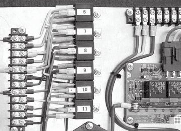
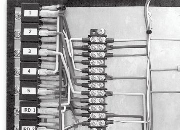
ASSEMBLIES & SCHEMATICS - AIR & ELECTRIC E-450 Circuit Board Assembly E-450 Shuttle Bus-Wiring Diagram E-450 Shuttle Bus - Drivers Side Wiring Diagram E-450 Shuttle Bus - Passenger Side & Rear Wiring Diagram F-550 Circuit Board Assembly Ver. 1 F-550 Circuit Board Assembly Ver. 2 E 450 & F-550 Circuit Board Assembly Ver. 3 F-550 Shuttle Bus -Wiring Diagram Misc. Air & Electrical Diagrams and Schematics
PARTS - SERVICE - WARRANTY
VENDOR REFERENCE LIST
INDEX
KRYSTAL ENTERPRISES VEHICLE WARRANTY
90
92
93
94
96
98
100
107
108112
116
118
124
Krystal Enterprises
Pre-Trip Inspection (suggested minimum)
Any item not passing inspection, must be reported immediately, before operating vehicle FAILURE OF HIGHLIGHTED ITEM(S) TO PASS INSPECTION WILL CAUSE VEHICLE TO BE GROUNDED
Inspection Procedure
Item 1 Check preventative maintenance schedule: for services due at present mileage 2 Check operation of: drivers seat and seat belt 3 Check operation of: steering wheel and shift levers 4 Check operation of: turn indicators 5 Check operation of: foot pedals and parking brake 6 Check operation of: all gauges, for normal readings with engine running 7 Check operation of: dash indicator lights with key on, engine not started, then again with
engine started
Pass Fail
8 Check operation of ventilation system: heating, defrosters, fans and air conditioning 9 Check: horn, wipers, washers, and mirrors for cleanliness, adjustment, operation and
damage
10 Check condition of: fi re extinguisher, warning refl ectors and fi rst aid kit 11 Check: all doors, glass and windows: for operation, cleanliness, and damage. 12 Check: all emergency exits for operation, warning devices, markings, to be free and clear 13 Check interior lighting: for operation and damage 14 Check Side Passenger Entry Door - Emergency Exit Operation & Sensitive Edge if equipped
Krystal Enterprises
Pre-Trip Inspection (suggested minimum)
Any item not passing inspection, must be reported immediately, before operating vehicle FAILURE OF HIGHLIGHTED ITEM(S) TO PASS INSPECTION WILL CAUSE VEHICLE TO BE GROUNDED
Inspection Procedure
Item 15 Check Side Passenger Entry Door: for damage and proper closing operation 16 Check exterior lighting: for operation and damage 17 Check exterior: for cleanliness, markings and damage 18 Check fuel cap: in place and secure 19 Check all tires and wheels: for tread depth, cracks & bulges, missing lug nuts, and air
pressure 80 psi for E-450 and 95 psi for F-550
Pass Fail
20 Check: oil level 21 Check: transmission fl uid level 22 Check: engine coolant level 23 Check: power steering fl uid level 24 Check: brake fl uid level 25 Check: belts for tension and wear 26 Check operation of: cameras, if applicable 27 Check operation of: PA system, if applicable 28 Check operation of: audio and video system, if applicable 29 Check wheelchair lift: for proper function or damage and securement station equipment
Krystal Enterprises
GENERAL VEHICLE SAFETY WARNINGS
NO STANDEES ARE ALLOWED, AT ANY TIME, WHILE THE VEHICLE IS IN MOTION. DISCONTINUE OPERATION OF THE VEHICLE, IF THE LOW AIR WARNING LIGHT COMES ON, OR UNTIL THE PROBLEM WITH THE SYSTEM CAN BE RESOLVED. DISCONTINUE OPERATION OF THE VEHICLE, IF ANY CRITICAL ITEM ON THE PRE-TRIP INSPECTION LIST FAILS TO PASS, OR UNTIL ALL PROBLEMS HAVE BEEN RESOLVED. IF A DOOR AJAR WARNING LIGHT IS LIT, CHECK ALL DOORS FOR PROPER CLOSURE. NEVER OPERATE THIS VE- HICLE UNTIL THE PROBLEM HAS BEEN RESOLVED. THIS BUS IS NOT DESIGNED TO TOW ANOTHER VEHICLE OR TRAILER DO NOT ATTEMPT TO TOW OR PULL ANOTHER VEHICLE WITH THIS BUS.
10
Krystal Enterprises
Vapor Air & Electric Door Operational Safety Check List
ATTENTION
WHEN OPERATING A VEHICLE WITH A VAPOR DOUBLE PANEL AIR OR ELECTRIC ACTUATED PASSENGER ENTRANCE DOORS, THE FOLLOWING PRECAUTIONS SHOULD BE TAKEN.
AIR DOORS
The Emergency Release Valve System - (must be checked on a daily basis) Once the emergency release valve has been actuated (by turning the red handle counter clockwise), it should be possible to open the doors by pushing outward with your hand after about 5 seconds.
The Obstruction Sensing System (Sensitive Edge) - (must be checked on a daily basis) Only when the door is closing, can reversing be actuated. The reversing motion should be shut off at about 10 to 30 mm before the fi nal closing position. If the reversing process actuates too late, the sensi- tivity of the differential pressure switch should be adjusted again. Call the KRYSTAL SERVICE DEPT.
ELECTRIC DOORS
The Emergency Release Lever System - (must be checked on a daily basis) Once the emergency release lever has been actuated (by pushing the red handle from right to left as indicated on the sticker), it should then be possible to open the doors by pushing the panels outward with your hand.
Krystal Enterprises
11
Air Door Emergency Release Valve
NTER CL O C K
W ISE
NOTE:
VALVE MUST BE CHECKED DAILY, PRIOR TO VEHICLE OPERATION
EMERGENCY USE ONLY
C A U T I O N ! For Emergency Door Opening, turn the red valve counter clockwise, this will release the door after about 5 seconds, then the door can be pushed open.
12
Krystal Enterprises
Electric Door Emergency Release Lever
Electric Door Motor Cover
EMERGENCY EXIT
PUSH HANDLE LEFT
PUSH DOORS OUT
EMERGENCY EXIT
PUSH HANDLE LEFT
PUSH DOORS OUT
Emergency Exit Lever Decal
EMERGENCY EXIT
PUSH HANDLE LEFT
PUSH DOORS OUT
Emergency Exit Lever
NOTE:
LEVER MUST BE CHECKED DAILY, PRIOR TO VEHICLE OPERATION
EMERGENCY USE ONLY
Krystal Enterprises
13
Wheelchair Securement and Occupant Restraint Systems
Pre-Trip Inspection
Is each securement station properly equipped with four securement straps, a lap belt, and a shoulder
belt?
Are all straps and belts in good working condition? Any defects such as cut, frayed, contaminated or damaged webbing, improperly functioning buckles or hardware, or broken or worn parts, require re- placement of the entire strap or belt assembly.
Are all fl oor anchorages, (i.e., tracks or plates), clear of dirt or debris to allow for proper system fi tting
attachment?
Is there a clean, dry container in the vehicle to allow for storage of the system when not in use? Is the vehicle equipped with a web/belt cutter for use in the event of an emergency evacuation? Are complete system operational instructions, in either printed or decal form, located within the vehicle
compartment to serve as a reference?
CAUTION! Never utilize the Occupant Restraint System unless you are fully trained, if you’re not sure what to do, always call your Kinedyne Representative for Assistance!
14
Krystal Enterprises
Typical Wheelchair Securement Methods
With the wheelchair and occupant facing toward the front of the vehicle, center the wheelchair between the fl oor tracks or plates. As you position the wheelchair, remember that the securement straps need to have approximately a 45° angle from the fl oor tracks or plates to where they attach to the frame. Also, keep in mind the proper extension and place- ment of the occupant restraint shoulder belt. Apply the wheel locks or turn off
Front Strap Attachment
Typical 4-Point Restraint with Lap & Shoulder Belt
Rear Strap Attachment
For Specifi c Operating Instructions and System Care and Maintenance, Refer to Your Kinedyne Literature
Lap Belt Attachment
Krystal Enterprises
15
Air Door Lock Pin Assembly
CAUTION! Security Pin must be removed during bus operation. Pin is only to be used for security, if bus is not in operation.
16
Krystal Enterprises
Dual Overhead Parcel Rack
CAUTION! Do not overload Parcel Racks. Do not fasten parcels to retainer bars.
Overhead Parcel Rack (right side shown)
Krystal Enterprises
17
Emergency Egress Window Operation
Lift up on lever to disengage latch
Windows with Emergency Exit stickers are designated emergency exits. Follow the directions on the sticker.
Lift levers and push window out
18
Krystal Enterprises
Emergency Roof Hatch Exit
This is a Dual Purpose hatch used for Emergency Egress and Ventilation purposes.
SUGGESTED MAINTENANCE Periodically inspect attaching fasteners for evidence of loosening due to tampering, and regularly clean surface with a mild soap and water.
CAUTION: When removing graffi ti, it is the customers responsibility to ensure cleaning solutions are compat- ible with the materials used on Safety Vents. Solutions containing, acetone, ether, lacquer thinner, or other sol- vents can destroy the high strength properties of many engineering plastics - AVOID these cleaners
EMERGENCY EXIT
PUSH BLACK TAB PUSH BLACK TAB PUSH BLACK TAB PUSH BLACK TAB PUSH BLACK TAB PUSH BLACK TAB PUSH BLACK TAB PUSH BLACK TAB PUSH BLACK TAB PUSH BLACK TAB PUSH BLACK TAB PUSH BLACK TAB PUSH BLACK TAB PUSH HANDLE OUT
For Emergency Exit
SEE MANUFACTURERS LITERATURE SEE MANUFACTURERS LITERATURE
FOR ADDITIONAL INFORMATION
PUSH UP TO OPEN
VENT HANDLE
Pull DOWN TO CLOSE
For Ventilation
Krystal Enterprises
19
Overhead Control Panels Assemblies
E-450 Overhead Control Panel
F-550 Overhead Control Panel
E-450 with PA in Console
Krystal Enterprises
20
Controls - Indicator and Accessory Switches
When the Low Air warning light is lit, this indicates the normal operating air supply has fallen below safe operating levels Discontinue Operation
The Low Battery Light indicates a low battery condition exists, and the Charge Protect System needs to be engaged.
The Hour Meter accumulates the number of hours your igni- tion has been turned on.
This switch turns on or off, the (optional) ceiling lights.
This switch must be on to power the (optional) Wheelchair Lift.
This switch operates (optional) Destination Sign when equipped.
This switch operates the (optional) in step heater when equipped.
Krystal Enterprises
21
Drivers Overhead Control Panel
1 Interior Lights 2 Reading Lights (optional) 3 Door Switch (open or close passenger door)
4 Door Open Indicator Light (WARNING DEVICE) 5 Rear Fan Control (hi - low - off)
6 Front Fan Control (hi - low - off) 7 Climate Control Mode (cool - off - heat) Note: Cool mode = A/C on both front & rear Heat mode = Heat from front unit only 8 Entrance Door Ajar Light ( WARNING DEVICE) 9 Rear Door Ajar Light (WARNING DEVICE)
22
Krystal Enterprises
Audio/Video PA Control Audio/Video PA Control
13
10
FRONT VIEW11
12
1 On/Off Volume Control - controls power and volume 2 Bass Control - increases or decreases bass 3 Treble Control - increases or decreases treble 4 Radio Mode - enables radio, indicator light will be on 5 PA Mode - enables PA, indicator light will be on 6 VCP Mode - enables VCP, indicator light will be on
7 VCP Power
REAR VIEW
8 VCP Play - starts the tape playing 9 VCP Fast Forward - fast forwards tape 10 VCP Stop - stops tape 11 VCP Replay - rewinds and replays from start of tape 12 VCP Rewind - rewinds tape 13 Paging Mode - (Internal or External) press button once to engage system, press again to toggle between internal/external
SEE MANUFACTURERS LITERATURE FOR ADDITIONAL INFORMATION
Krystal Enterprises
23
HIC900 Throttle Controller Operating Procedures
Quick Reference Guide
BCP (Battery Charge Protection Mode) Note: This system has been set-up for Automatic Battery Charge Protection, which becomes active whenever the following enabling conditions are met:
ENABLING CONDITION: Vehicle NOT moving (speed=0 MPH). Service Brake NOT pressed. Vehicle Transmission Range in Park/Clutch NOT pressed. RPM's inside of safe operating range. Transmission Fluid Temperature below 240˚ F. Engine Coolant Temperature below 230˚ F. Brake Lights Functional Foot Off Accelerator Pedal
AUTOMATIC BATTERY CHARGE PROTECTION Any time your vehicle is Powered-up”, Charge Protection is auto- matically engaged, THIS FUNCTION SHOULD NOT NORMALLY BE DISABLED. Charge Protection will remain in effect until which time, any of the above stated ENABLING CONDITIONS are no longer met, or until you manually dis-engage the BCP button on the DRIVERS OVERHEAD CONTROL PANEL, see photo at right.
TO DEACTIVATE “AUTOMATIC BATTERY CHARGE PROTEC- TION” OR “FAST IDLE” Do the following: Press the Manual Engage button on the DRIVERS OVERHEAD CONTROL PANEL and release.
Fast Idle system will only be turned off when the button is re- leased.
To exit “AUTOMATIC CHARGE PROTECTION Mode”, simply depress the service brake pedal. See the Off Road Engineering literature for specifi c details regarding other operating parameters.
Fast Idle Switch is shown as mounted
on Driver’s Overhead Control Panel (ref. page 20)
24
Krystal Enterprises
HIC900 Throttle Controller Wiring Diagram - DIESEL
Ford Diesel Engine
Vehicle SEIC Wiring
User Interface To +12V
fused ignition Hot-in-Run
10K 10Turn Potentiometer
Ground
Diesel Engine SEIC Wires Orange/Yellow Purple/Lt Blue Orange/Yellow
E-Series F-Series
PTO_RPM
Orange PTO
RPM1
DIESEL RPM
RPM2
RPM3BVP
VAR
GAS RPM
N/C
PTO
12V
GND
Ignition Fused Hot-in-Run +12V
Ground
+12V OUT
Orange
PTO ENGAGE
N/C
PTO GND
Ground
High Idle switch wire (optional)
HIGH
IDLE
+12V IN
Black
To Ground
Krystal Enterprises
25
HIC900 Throttle Controller Wiring Diagram - GASOLINE
User Interface To +12V
fused ignition Hot-in-Run
10K 10Turn Potentiometer
Ground
Ford Gasoline Engine
RPM1
RPM2
RPM3BVP
VAR
DIESEL RPM
N/C
GAS RPM
PTO
12V
GND
PTO ENGAGE
PTO GND
Ignition Fused Hot-in-Run +12V
Ground
PTO Indicator Orange/Lt Blue Orange/Lt Blue
PTO
Engage Orange/White Orange/White
E-Series F-Series
PTO RPM
Select
PTO Mode Orange Orange/Yellow Orange/Yellow Orange
26
Gasoline Engine SEIC Wires
Vehicle SEIC Wiring
Krystal Enterprises
Charge Protection System Components
E-450 Charge System Fuse, located behind panel & Rear Ignition Power Fuse (shown with kick panel removed)
E-450 Charge Isolator Solenoid located in engine compartment -drivers side. (diesel version shown)
Gas version is located below primary battery.
F-550 Charge System F-550 Charge System F-550 Charge System and Rear Power Fuse and Rear Power Fuse and Rear Power Fuse (located behind panel (located behind panel (located behind panel under steering column)
F-550 Charge Isolator F-550 Charge Isolator Solenoid (located in engine Solenoid (located in engine compartment-drivers side) compartment-drivers side)
Krystal Enterprises
27
Battery Location - Primary and Secondary
F-550 Primary Battery Location
F-550 Diesel Engine Compartment
F-550 Primary Battery Location
E-450 Diesel Primary Battery Location Battery Location
E-450 2004 and Older Models
E-450 2005 and Newer Models
Under Floor Auxiliary Battery (curb side) for E-450 & F-550 (E-450 diesel shown)
E-450 2004 and Older Models
E-450 Diesel Engine Compartment
Krystal Enterprises
28
2005 E-450 Primary & Secondary Slide Out Battery Compartment Located on Curb Side of Vehicle
E-450 Heated Mirror Switch and Mirror Control Switch
C A U T I O N ! Leaving the heated mirror switch on in hot weather, may cause mirror to crack.
Heated Mirror Switch This switch controls the ON/OFF activation of the heated mirror function.
Mirror Control Switch This switch includes a center toggle switch that allows the operator to switch from right to left mirror. The center posi- tion of the toggle defeats all mirror operations. When either the left or right mirror is engaged, the 4 arrow switches allow the mirror to move in 4 different directions for precise adjustment.
Krystal Enterprises
29
Video Entertainment Center
Basic Operating Instruction Bulkhead mounted TV and DVD
[The TV may be viewed with or without using the DVD]
For specifi c detailed information see
Manufacturers DVD Operating Instructions.
1. Turn on the TV using the power on the TV or the button on the remote (Note: TV must be set to Video #1 for DVD to work)
2. To view video, push the TV/Video button to switch between TV and DVD(Video). 3. To view tapes select VCP, then press the DVD power button on the remote. 4. The DVD buttons on the remote will now Operate all the functions of the DVD
SEE MANUFACTURERS LITERATURE
FOR ADDITIONAL INFORMATION
ON BOTH COMPONENTS
Bulkhead Mounted TV and DVD
Krystal Enterprises
30
Back-Up Camera Controls and Operation
NOTE: To reverse image on monitor, push button on back of camera
LCD Monitor
(located in bulkhead above passenger seat on E-450
or in dash area on passenger side of F-550)Monitor Controls
1. Power Button, glows dimly when system is connected fully manual, be- coming bright upon activation 2. A/B input Select Button, toggles active display between AV1 and AV2 inputs 3. Day/Night Mode Button, toggles intensity of LCD screen for day or night operation, (day=maximum intensity, night=less intensity) 4. Picture Adjustment Menu Button, accesses on-screen-display, to adjust (brightness, contrast, color, tint). Use the Volume control to adjust each up or down, as indicate by a bar graph at bottom on screen. 5. Volume Button, controls +- output volume of built-in speaker, when feature is connected. Also used in Picture Adjustment Mode.
Back-Up Camera
(located on rear of vehicle)
System Operation
This system consists of two major components: 1. The Back-Up Camera 2. LCD Monitor
The system may be connected two ways: 1. Fully manual, requiring the power button on the LCD Monitor to be pushed to energize the system and activate the monitor. 2. Automatic, which activates the monitor when- ever the ignition is turned to accessory or the engine is started.
SEE MANUFACTURERS LITERATURE
FOR ADDITIONAL INFORMATION
Krystal Enterprises
31
Rear Step Operation
Rear Step Switch Guard
SEE MANUFACTURERS LITERATURE
FOR ADDITIONAL INFORMATION
Rear Step
Operational Schematic Operational Schematic
For the double rear step (shown above) and the single rear step, operation is the same. The schematic (this page) explains the electri- cal operation of both steps. The power switch allows you to enable or disable step operation. When the step is enabled, opening the rear door automatically extends the step. Note: See Manufacturers literature regarding periodic lubrication requirements.
32
Krystal Enterprises
Rear Cargo Door Micro Switch
Cargo Door Micro Switch
The switch is located at the rear cargo door upper hinge, shown at left and above. It operates the rear interior lights and also activates the door-ajar light on the front overhead control panel. This switch works in conjunction with the rear step, allowing the power switch (shown on previous page) to enable or disable step operation.
Rear Door and Hinge Assy
Krystal Enterprises
33
Fold Forward
Foldaway Seating
Lift Rearward
Lever “A” Push/Release
Lever “B”
Lift
Pull Towards Aisle Until Down Lock Engages
Push in Lever “D”
Truss Lock “C”
Front
Rotate Clockwise To Lock, Counter-Clockwise to Unlock
To Lower 1. Rotate the Truss Lock “C” to unlock the assembly, then push Lever “D” and pull the top of the seat toward the aisle until it is locked in the down position. 2. Push lever “A” forward, and lift the back cushion until the lever “A” has snapped back into the locked position.
To Raise 1. Push lever “A” forward, and fold the back cushion down against the seat cushion until lever has snapped back into locked position. 2. Push lever “B” upward, and lift the seat into the fold away position, and rotate the Truss Lock “C” to lock the assembly in place.
Krystal Enterprises
34
Bus Passenger Seating - Moving or Adding
Bus seating is mounted into the fl oor of the vehicle as shown in the photo to the left. To move or add seating: 1. Remove the black plastic track cover, so the track is exposed. 2. Next remove the nut from the base. NOTE: Nut must be perpen- dicular to the track when the seat is re-attached to the seat track. CAUTION: Bolts must be torqued to 35 ft.. Lbs.
Caution: When Adding Seating, Do Not Exceed Weight Distribution/ Payload Limitations.
Krystal Enterprises
35
Stainless Steel Wheel Liners
C A U T I O N ! Wheel liners should only be removed Wheel liners should only be removed Wheel liners should only be removed using the Wheel Liner Tool provided using the Wheel Liner Tool provided using the Wheel Liner Tool provided with your vehicle. Damage could with your vehicle. Damage could with your vehicle. Damage could occur if the supplied tool is not used. occur if the supplied tool is not used. occur if the supplied tool is not used.
Lug
Jam Nut Cover Pop Out Center Hub Center Emblem
Wheel Liner Tool
INSTALLATION - REMOVAL INSTRUCTIONS
NOTE: When removing or installing, never remove the original equipment lug nuts. 1. TO REMOVE, simply place the Wheel Liner Tool over the Jam Nut Covers. 2. Remove Jam Nut Covers from each wheel and remove Liners
1. TO INSTALL, determine the correct placement of liners for proper hand hole
alignment.
2. Install Liner over studs, then install Jam Nut Covers w/built-in jam nuts onto the
studs. Using the Wheel Liner Tool, tighten all Jam Nuts
Turn
Front Wheel Liner
Installation Tool
Jam Nut Cover Assy
Hub Center Emblem
Turn
SEE MANUFACTURERS LITERATURE FOR ADDITIONAL INFORMATION
Rear Wheel Liner
Installation Tool
36
Krystal Enterprises
Front Wheel
Lug
Rear Wheel
Air Conditioning Assembly E-450 & F-550
ACC Front Air Conditioning These units also provide heat when A/C is not required, by toggling switch on the overhead control panel
Optional ACC Rear Air Conditioning This unit only operates when the dash A/C is turned on.
A/C only - No Heat
These units are operated by the driver, using the controls on the Overhead Control Panel , see page 22.
For information on A/C charging specifi cations, see the A/C Charging Chart on page 67.
Krystal Enterprises
37
Rear Floor Heater Assembly E-450 & F-550
30,000 BTU Model
65,000 BTU Model
Both units are turned on when the heat mode is selected on the Drivers Overhead Control Panel (see page 22)
38
Krystal Enterprises
THIS PAGE IS INTENTIONALLY BLANK
Krystal Enterprises
39
Standard Movable Wall - Front View
Caution: When Adding Seating, Do Not Ex- ceed Weight Distribution/Payload Limitations
Movable Wall shown above in the forward position
Krystal Enterprises
40
Standard Movable Wall - Rear View
The standard movable wall can be moved by doing the following: 1. Remove the seats from in front of the wall 2. From the baggage compartment side, remove the plastic track cover on both the side wall and fl oor to expose the track. 3. Disengage the top latches at the outside corners of the wall. 4. From the front side of the wall, loosen the bolts.
5. With assistance on both sides of the wall, push evenly on both sides and slowly move the wall to the desired position. 6. When securing wall, make sure to re torque all bolts to 35 ft.. lbs. Note: if seats are installed, seat bolts must also be torqued to 35 ft.. lbs. 7. Replace all plastic track covers and engage top latches
Krystal Enterprises
41
E-Z Move Wall - Open Front
Caution: When Adding Seating, Do Not Ex- ceed Weight Distribution/Payload Limitations
E-Z Move Wall Operating Instructions
Movable Wall to the open position (with luggage compartment)
1) Release the top two clamps located on the ceiling. 2) Enter bus through the rear door and release bottom clamp 3) Push the movable wall at the upper most centrally located handle to the stop 4) Release the divider clamp and slide out each divider half. Rotate the
clamp assembly into the seat track and engage clamps. SAFETY ALERT
5) Engage the top two clamps into the locked position SAFETY ALERT
Clamps must be locked down before operating vehicle
SAFETY ALERT
Movable Wall to the closed position (no luggage compartment)
1) Release the top two clamps located on the ceiling. 2) Enter bus through the rear door. 3) Release and rotate the clamp assembly (divider) out of the seat track. Slide the divider to the stop and engage the divider clamp to lock down the dividers.
4) Pull the movable wall at the upper most centrally located handle to the stop. 5) Engage the bottom clamp into the receiver located in the fl oor. SAFETY ALERT 6) Close the rear door. Enter the bus, walk to the rear and engage the top
two clamps into the locked position. SAFETY ALERT
SAFETY ALERT
Clamps must be locked down before operating vehicle.
42
Krystal Enterprises
E-Z Move Wall - Open Rear
To Open and Close E-Z Move Wall
Instructions for Opening and Closing the E-Z Move Wall shown on the previous page, may also be found mounted on the back of the Movable Wall. Follow the instructions for Open Position - (with luggage com- partment) or Close Position - (no luggage compartment)
SAFETY ALERT: ALL CLAMPS MUST BE LOCKED DOWN BEFORE OPERATING VEHICLE
Krystal Enterprises
43
E-Z Move Wall Clamp Assemblies
LH & RH Lower Clamp Assembly
( LH shown)
Center Lower Clamp Assembly
LH & RH Ceiling Clamp Assembly
(RH shown)
SAFETY ALERT: ALL CLAMPS MUST BE LOCKED DOWN BEFORE OPERATING VEHICLE
44
Krystal Enterprises
Compressed Air Supply Assembly
Pre-Filter Air Dryer Compressor Check Valve Pressure Switch Over Temperature Sensor Solenoid Switch
On the F-550 (shown above) The air supply compressor assembly is locat- ed beneath the fl oor hatch, between the passenger seats midway back on the right side of the vehicle. On the E-450 the air supply com- pressor is located beneath the fi rst right hand side passenger seat.
Krystal Enterprises
45
Air Operated - Single Plug Door
4-Way Valve
Entry Door Ajar Switch Closing Cushioning
Valve Closing Speed Valve
Opening Speed Valve
Opening Cushioning
Valve
CAUTION! Never attempt adjustment of the Boomerang Arm, call KRYSTAL SERVICE
Single Plug Door System (door shown partially open)
Air Door Speed Adjustment Procedure 1. Remove the air motor cover located in the stepwell. 2. Using the photo on this page, identify the speed control valves. Using a 3/8” wrench, loosen the locknuts on both valves. 3. Operate the door and adjust both valves until the opening and closing speeds are equal and acceptable. Then tighten both
4. Using a fl at blade screwdriver, adjust the opening and closing cushioning valves on the air motor, then replace cover.
locknuts.
46
Krystal Enterprises
Secondary Entry Door Switch - used on air operated door systems, located on passenger door post
Compressed Air Schematic - Single Plug Door Compressed Air Schematic - Single Plug Door
FOR 2004 &
OLDER MODELS
DETAIL FOR 2005 & NEWER MODELS
4 WAY SOLENOID VALVE
AIR PILOT
CLOSE VALVE (CUSHIONING)
BLUE
TEE
DOOR SWITCH ELECTRONIC PANEL
YELLOW
CLOSE
OPEN
DOOR MOTOR
SPEED CONTROL VALVES
OPEN VALVE (CUSHIONING)
Krystal Enterprises Krystal Enterprises
47
Air Operated - Double Plug Door
ATTN: Double Plug Air Door Speed Is Factory Set ATTN: Double Plug Air Door Speed Is Factory Set If adjustments become necessary, do not attempt adjustments. Contact the Krystal Service Dept., at 1-800-Krystal (579-7825)
CAUTION! The Emergency Release Valve System - (must be checked on a daily basis) Once the emergency release valve has been actuated (by turning counter clockwise), it should be possible to open the doors by pushing outward with your hand after about 5 seconds.
The Obstruction Sensing System (Sensitive Edge) - (must be checked on a daily basis) Only when the door is closing, can reversing be actuated. The reversing motion should be shut off about 10 to 30 mm before the fi nal closing position. If the reversing process actuates too late, the sensitivity of the differential pressure switch would require re-adjustment. Call the KRYSTAL SERVICE DEPT.
Secondary Entry Door Switch - used on air operated door systems, located on passenger door post
48
Krystal Enterprises
Compressed Air Schematic - Double Plug Doors
Air Schematic for Double Plug Doors Air Schematic for Double Plug Doors
Electrical Schematic for Doors with Sensitive Edge
Double Plug Door System w/Sensitive Edge
(doors shown partially open)
For Larger Schematics See Electrical Section pg 108-109
Krystal Enterprises
49
Electric Swing Doors
Electric door motor Cover
EMERGENCY EXIT
PUSH HANDLE LEFT
PUSH DOORS OUT
Electric door motor with control arm
For removal of door motor cover 1. Remove black rubber strip from molding channel 2. Remove exposed screws in aluminum channel 3. Remove screws from 3 corners of cover
EMERGENCY EXIT
PUSH HANDLE LEFT
PUSH DOORS OUT
Emergency Exit Lever Decal
NOTE:
LEVER MUST BE CHECKED DAILY, PRIOR TO VEHICLE OPERATION
Electric Door Adjustment Procedure
Door Speed Is Factory Set
If adjustments become necessary, do not attempt adjustments. Contact the Krystal Service Dept., at 1-800-Krystal (579-7825)
50
Krystal Enterprises
Swing Door System - Electrical Schematic
Swing Door System
E-450 Schematic
For Larger Schematics See Electrical Section pg 110-111
F-550 Schematic
Krystal Enterprises
51
Lift Motor Assy
Braun Rear Door Wheelchair Lift
User Instructions
Passenger Loading and Unloading
Do not exceed the 800 pound load capacity of the lift. Prior to lift operation, the lift should be inspected for proper function. If any problems exist, DO NOT USE LIFT. Contact Braun Corp. at 1-800-THE LIFT for repair. Passengers loading from the ground level, should back onto the platform. All passengers loading onto the platform, should be positioned fully within the yellow boundaries, facing outward from the vehicle, with the wheelchair locks locked, gripping handrails if able. Electric wheelchairs should be turned off.
UNFOLD The UNFOLD function deploys the lift from the upright position, UNFOLD with the platform extended fl at at fl oor level, with the roll stop vertical. with the platform extended fl at at fl oor level, with the roll stop vertical. FOLD The FOLD function raises the lift from the horizontal fl oor level position, FOLD bringing the platform back to a full upright position bringing the platform back to a full upright position DOWN The DOWN function lowers the platform to the ground level, and DOWN extends the roll stop to a fl at position, for wheelchair egress. extends the roll stop to a fl at position, for wheelchair egress. UP The UP function raises the roll stop to full vertical position, before raising UP the platform from ground level to the fl oor level position for unloading. the platform from ground level to the fl oor level position for unloading. C A U T I O N ! Never raise or lower lift if roll stop is malfunctioning C A U T I O N ! C A U T I O N !
C A U T I O N ! C A U T I O N ! C A U T I O N ! C A U T I O N ! C A U T I O N ! YOU MUST READ AND UNDERSTAND THE MANUFACTURERS YOU MUST READ AND UNDERSTAND THE MANUFACTURERS OPERATORS MANUAL BEFORE EVER OPERATING THIS LIFT
Back-up Pump
Lift Control Pump Handle
Release Valve
52
Krystal Enterprises
Braun Rear Door Wheelchair Lift
Lift Closed
Lift Extended
Lift Lowered
In the event of an electrical system failure, this lift system provides for full manual op- eration. Locate the back-up pump release valve, and the hand pump handle on the motor housing. To Unfold the Platform 1. Place the slotted end of the pump handle onto the back-up pump release valve, and
Emergency Back-Up Operation turn counterclockwise until the platform reaches fl oor level. 2. Turn the release valve clockwise to stop the platform (make sure valve is tight but not over tight) To Lower Platform and Roll Stop 1. Repeat step 1 in the previous procedure to lower the lift to the ground level.
To Fold Roll Stop and Raise Platform 1. Place the slotted end of the pump handle onto the back-up pump release valve, and turn clockwise to close valve. 2. Insert handle into back-up pump, and pump until platform reaches fl oor level. To Fold Platform Up 1. Repeat step 2 above until fully upright.
Note: Refer to Operator’s Manual for Detailed Operating & Maintenance Procedures
Krystal Enterprises
53
Lift Motor Assy
Ricon Rear Door Wheelchair Lift
Basic User Instructions
Passenger Loading and Unloading
ATTENTION! When the green light is lit, the lift needs service Do not exceed the 800 pound load capacity of the lift. Prior to lift operation, the lift should be inspected for proper function. If any problems exist, DO NOT USE LIFT. Contact Ricon Corp. at 1-818-322-2884 for repair. Passengers loading from the ground level, should back onto the platform. All passengers loading onto the platform, should be positioned centrally on the platform, facing outward from the vehicle, with the wheelchair locks locked, and restraint belt fastened. Electric wheelchairs should be turned off.
UNFOLD The UNFOLD function deploys the lift from the upright position, with the platform extended fl at at fl oor level, with the roll stop vertical. FOLD The FOLD function raises the lift from the horizontal fl oor level position, bringing the platform back to a full upright position DOWN The DOWN function lowers the platform to the ground level, and ex- tends the roll stop to a fl at position, for wheelchair egress. UP The UP function raises the roll stop to full vertical position, before raising the platform from ground level to the fl oor level position for unloading. C A U T I O N ! Never raise or lower lift if roll stop is malfunctioning C A U T I O N ! C A U T I O N ! C A U T I O N ! YOU MUST READ AND UNDERSTAND THE MANUFACTURERS YOU MUST READ AND UNDERSTAND THE MANUFACTURERS OPERATORS MANUAL BEFORE EVER OPERATING THIS LIFT
Back-up Pump Pump Handle
(not shown)
Lift Control Release Valve
54
Krystal Enterprises
Ricon Rear Door Wheelchair Lift
Lift Closed
Lift Extended
Lift Lowered
In the event of an electrical system failure, this lift system provides for full manual op- eration. Locate the back-up pump release valve, and the hand pump handle on the motor housing. To Deploy the Platform 1. Place the slotted end of the pump handle onto the back-up pump release valve, and turn
Emergency Back-Up Operation counterclockwise ¼ turn until the platform reaches fl oor level. 2. Turn the release valve clockwise to stop the platform (make sure valve is tight but not over tight) To Lower Platform and Roll Stop 1. Repeat step 1 in the previous procedure to lower the lift to ground level.
To Fold Roll Stop and Raise Platform 1. Place the slotted end of the pump handle onto the back-up pump release valve, and turn clockwise to close valve. 2. Insert handle into back-up pump, and pump until platform reaches fl oor level. To Stow Platform Up 1. Repeat step 2 above until fully upright.
Note: Refer to Operator’s Manual for Detailed Operating & Maintenance Procedures
Krystal Enterprises
55
Braun UVL 600X Series Under Vehicle Wheelchair Lift
User Instructions
Passenger Loading and Unloading
Do not exceed the 750 pound load capacity of the lift. Prior to lift operation, the lift should be inspected for proper function. If any problems exist, DO NOT USE LIFT. Contact Braun Corp. at 1-800-THE LIFT for repair. Passengers loading from the ground level should back onto the platform. All passengers loading onto the platform, should be positioned in the center of the platform, facing outward from the vehicle, with the wheelchair locks locked.
The UP function deploys the lift from stow position, and raises the
UP platform to fl oor level. DOWN The DOWN function deploys the lift form the stowed position, lowers the platform to ground level and lowers the front barrier after reaching the ground. STOW The STOW function raises or lowers the platform to the stowed level, and then moves it inward to the stow position. DOOR CLOSE (Optional) The DOOR CLOSE function only operates when automatic door openers are installed. The function only operates when the platform is stowed or fully extended at ground level.
C A U T I O N ! YOU MUST READ AND UNDERSTAND THE MANUFACTURERS OPERATORS MANUAL BEFORE EVER OPERATING THIS LIFT
Krystal Enterprises
Pump Motor
Lift Control
Pump Handle
56
Braun Under Vehicle Wheelchair Lift
Lift Closed Lift Closed
In the event of an electrical system failure, the UVL system provides for full manual operation. Locate the manual release cable, manual down valve, and the hand pump on the power pack. To move platform from STOW, pull the manual release cable. Twist the “T” handle to lock in the released position. The plat-
Lift Extended Lift Extended
Lift Lowered Lift Lowered Emergency Back-Up Operation form can now be pulled outward. To raise the platform, make sure the manual down valve is turned fully clock- wise. Pump the hand pump handle until you reach the desired platform height. To lower the platform, turn the manual down valve SLOWLY counter-clockwise to lower the platform. To lower the front
Lift Raised Lift Raised
barrier, remove the release pin at the barrier actuator end. Lift will not continue operating unless release pin is re-inserted fully. To move platform to STOW po- sition, fi rst be sure the platform is at STOW height. Pull and lock the manual release cable. Push the platform inward to re-engage release cable mechanism.
Note: Refer to Service Manual for Maintenance, Adjustment, and Trouble Shooting Procedures
Krystal Enterprises
57
Standard Chassis Specifi cation for E450 Super Duty RV Cutaway
Chassis GVWR - Total Front Axle Front Springs Stabilizer Bar Rear Axle Type Rear Axle Ratio Rear Springs Shock Absorbers Engines
Fast Idle Controller
Transmission Alternator
Batteries - Chassis Batteries - Coach
E-450 Super Duty RV Cutaway 14,050 lbs Twin I-Beam Coil - Computer Selected Front & Rear Full Floating Gas=4.63 Diesel=4.10
Leaf Gas Pressurized 6.8 Liter Triton EFE V-10 Gas 6.0 Liter Power Stroke V-8 Diesel Gas - Penntex Diesel - Ford or InterMotive Torque Shift 5-Speed Automatic w/Tow Haul Mode Gas - Pentex 200 Amp Diesel - Ford Dual 110 Amp Dual 84 & 63 AMP HR, 1400 CCA Single 112 AMP HR, 800 CCA Deep Cycle Marine58
Krystal Enterprises
Standard Chassis Specifi cation for E450 Super Duty RV Cutaway
Steering Steering Column Brakes Fuel Tank Cab Paint Glass Lights Air Conditioner Heater/Defroster Safety Air Bags Windshield Wipers Gauges/Instrumentation Mirrors Tires Wheels Wheelbase
Power Assisted Locking, Energy Absorbing, Tilt w/ Cruise Control 4 Wheel ABS Power Disc Brakes 55 Gallon Oxford White Tinted All Windows, Power Assisted Door Halogen Sealed Beam Headlights 8,000 BTU Cab with R-134a 4-Speed Fan 3-Point Shoulder/ Lap Belts Dual Safety Restraint System Intermittent Voltmeter, Oil Pressure, Temperature, Fuel Gauge Heated/ Power Remote 10” x 7” LT225/75R16
16.5” 8 - Hole, Stamped Steel KK22=158”, KK24=176”, KK28=209”Krystal Enterprises
5959
Standard Equipment on E450 Shuttle Buses
• 6.8 Liter Fuel Injected V-10 Gas Engine • Power Steering • 4-Wheel ABS Power Disc Brakes • Heavy Duty Dual Batteries • Electronic 4-Speed Auto Transmission • Radial Tires LT225/75R16
• 50 States Emissions • 55 Gallon Fuel Tank • Adjustable Tilt Steering Wheel • Cruise Control • Engine Oil Cooler • Transmission Oil Cooler • Automatic High Idle Controller • Drive Shaft Guards • .063 Aluminum Exterior Side Walls • Welded Steel Cage Frame • Cab Running Boards • Captains Chairs - Driver/Co-Pilot • 3/4” Resin Laminated Floor • 2” Fiberglass Insulation • Commercial Grade Carpet• Ribbed Rubber Aisle • Mid-High Seats with Level 3 Fabric • 53,000 BTU A/C System • AM/FM Stereo Cassette w/CD & Clock • Power Cab Door Locks • Power Cab Windows • Back-up Alarm • Valance Lighting • Air Actuated Sedan Entry Door • Full Body Undercoating • Base White Body Color • Power Remote/Heated Mirrors • 80% Tinted Windows w/UV Protection • 200 Amp Alternator (Gas) • Dual 110 Amp Alternator, (Diesel) • Brake Interlock (for wheelchair only) • S/S Wheel Inserts • Movable Luggage Partition (KK28) • Rear Luggage Door w/Electric Step (KK28) • Sedan Style Wheelchair Lift Door (KK22W &
KK24W)
60
Krystal Enterprises
Standard Chassis Specifi cation for F550 Super Duty Cab & Chassis
GVWR - Total Front Axle Front Springs Stabilizer Bar Rear Axle Type Rear Axle Ratio Rear Springs Shock Absorbers Engines
Fast Idle Controller
Transmission Alternator
Batteries - Chassis Batteries - Coach
19,000 lbs Mono-Beam Twin Coil Front & Rear Full Floating 4.88 (Gas & Diesel) Leaf, Single Stage, Constant Rate & Auxiliary HD Gas Pressurized 6.8 Liter Fuel Injected V-10 Gas Engine 6.0 Liter Power Stroke V-8 Diesel Gas - Penntex Diesel - Ford or InterMotive Torque Shift 5-Speed Automatic w/Tow Haul Mode Gas - Pentex 200 Amp Diesel - Ford Dual 110 Amp Dual Maintenance Free 78 Amp Hr, 1300 CCA Single 112 AMP HR, 800 CCA Deep Cycle Marine
Krystal Enterprises
6161
Standard Chassis Specifi cation for F550 Super Duty Cab & Chassis
Steering Steering Column Brakes Fuel Tank Cab Paint Glass Lights Air Conditioner Heater/Defroster Safety Air Bags Windshield Wipers Gauges/Instrumentation
Mirrors Tires Wheels Wheelbase
Power Assisted Locking, Energy Absorbing, Tilt w/ Cruise Control 4 Wheel ABS Power Disc Brakes 40 Gallon w/19 Gallon Aux. Tank Oxford White Tinted All Windows, Power Assisted Door Halogen Sealed Beam Headlights 8,000 BTU Cab with R-134a 4-Speed Fan 3-Point Shoulder/ Lap Belts w/Adjustable D-Rings Dual Safety Restraint System Intermittent Tachometer, Trip Odometer, Voltmeter, Oil Pressure, Coolant Temperature, Fuel Gage, Indicator Lights Heated/ Power Remote 10” x 7” LT225/70R19.5
19.5” 8 - Hole, 8-Lug Steel KK30=218”, KK33=250 ⅜”62
Krystal Enterprises
Standard Equipment on F550 Shuttle Buses
• 6.8 Liter Fuel Injected V-10 Gas Engine • Power Steering • 4-Wheel ABS Power Disc Brakes • Heavy Duty Dual Batteries • Electronic 4-Speed Auto Transmission(gas only) • Radial Tires LT225/70R19.5
• 50 States Emissions • 40 Gallon Fuel Tank w/19 Gallon Aux. Tank • All Season Radial Tires LT225/75R16F • Adjustable Tilt Steering Wheel • Cruise Control • Engine Oil Cooler • Transmission Oil Cooler • Automatic High Idle Controller • Drive Shaft Guards •.063 Aluminum Exterior Side Walls • Welded Steel Cage Frame • Cab Running Boards • Captains Chair Driver & Co-Pilot • 3/4” Resin Laminated Floor • 2” Batted Fiberglass Insulation • Commercial Grade Carpet• Ribbed Rubber Center Aisle • Mid-High Seats with Level 3 Fabric • 68,000 BTU A/C System w/Dual Compressors • AM/FM Stereo Cassette • Power Cab Door Locks • Power Cab Windows • Back-up Alarm • Valance Lighting • Air Actuated Sedan Style Entry Door • Full Body Undercoating • Base White Body Color • Power Remote Side View Mirrors • 80% Tinted Windows w/UV Protection • 200 Amp Alternator (Gas) • Dual 110 Amp Alternator, (Diesel) • Vented Emergency Escape Hatch • S/S Wheel Inserts • Movable Luggage Partition (KK30/KK33) • Rear Luggage Door w/Electric Step (KK30/KK33) • Sedan Style Wheelchair Lift Door (KK30W &
KK33W)
Krystal Enterprises
6363
General Vehicle Dimensional Specifi cations-Body & Chassis by Model
Features Models
GVWR Wheelbase Overall Length Turning Radius Interior Body Length (without Luggage) Clear Door Opening - Luggage Door Clear Door Opening - Single Plug Clear Door Opening - Double Plug Clear Door Opening - Swing Doors Clear Door Opening - Wheelchair Lift Door Exterior Height Exterior Width (excluding Mirrors) Exterior Width (including Mirrors) Interior Width - at Floor Interior Width - at Shoulder Aisle Width
KK22
KK24
KK28
KK30
KK33
14,050 #
14,050 #
14,050 #
19,000 #
19,000 #
158” 23’ 0” 28’ 5” 178”
176” 25’ 6”