- Download PDF Manual
-
51
Lift Motor Assy
Braun Rear Door Wheelchair Lift
User Instructions
Passenger Loading and Unloading
Do not exceed the 800 pound load capacity of the lift. Prior to lift operation, the lift should be inspected for proper function. If any problems exist, DO NOT USE LIFT. Contact Braun Corp. at 1-800-THE LIFT for repair. Passengers loading from the ground level, should back onto the platform. All passengers loading onto the platform, should be positioned fully within the yellow boundaries, facing outward from the vehicle, with the wheelchair locks locked, gripping handrails if able. Electric wheelchairs should be turned off.
UNFOLD The UNFOLD function deploys the lift from the upright position, UNFOLD with the platform extended fl at at fl oor level, with the roll stop vertical. with the platform extended fl at at fl oor level, with the roll stop vertical. FOLD The FOLD function raises the lift from the horizontal fl oor level position, FOLD bringing the platform back to a full upright position bringing the platform back to a full upright position DOWN The DOWN function lowers the platform to the ground level, and DOWN extends the roll stop to a fl at position, for wheelchair egress. extends the roll stop to a fl at position, for wheelchair egress. UP The UP function raises the roll stop to full vertical position, before raising UP the platform from ground level to the fl oor level position for unloading. the platform from ground level to the fl oor level position for unloading. C A U T I O N ! Never raise or lower lift if roll stop is malfunctioning C A U T I O N ! C A U T I O N !
C A U T I O N ! C A U T I O N ! C A U T I O N ! C A U T I O N ! C A U T I O N ! YOU MUST READ AND UNDERSTAND THE MANUFACTURERS YOU MUST READ AND UNDERSTAND THE MANUFACTURERS OPERATORS MANUAL BEFORE EVER OPERATING THIS LIFT
Back-up Pump
Lift Control Pump Handle
Release Valve
52
Krystal Enterprises
Braun Rear Door Wheelchair Lift
Lift Closed
Lift Extended
Lift Lowered
In the event of an electrical system failure, this lift system provides for full manual op- eration. Locate the back-up pump release valve, and the hand pump handle on the motor housing. To Unfold the Platform 1. Place the slotted end of the pump handle onto the back-up pump release valve, and
Emergency Back-Up Operation turn counterclockwise until the platform reaches fl oor level. 2. Turn the release valve clockwise to stop the platform (make sure valve is tight but not over tight) To Lower Platform and Roll Stop 1. Repeat step 1 in the previous procedure to lower the lift to the ground level.
To Fold Roll Stop and Raise Platform 1. Place the slotted end of the pump handle onto the back-up pump release valve, and turn clockwise to close valve. 2. Insert handle into back-up pump, and pump until platform reaches fl oor level. To Fold Platform Up 1. Repeat step 2 above until fully upright.
Note: Refer to Operator’s Manual for Detailed Operating & Maintenance Procedures
Krystal Enterprises
53
Lift Motor Assy
Ricon Rear Door Wheelchair Lift
Basic User Instructions
Passenger Loading and Unloading
ATTENTION! When the green light is lit, the lift needs service Do not exceed the 800 pound load capacity of the lift. Prior to lift operation, the lift should be inspected for proper function. If any problems exist, DO NOT USE LIFT. Contact Ricon Corp. at 1-818-322-2884 for repair. Passengers loading from the ground level, should back onto the platform. All passengers loading onto the platform, should be positioned centrally on the platform, facing outward from the vehicle, with the wheelchair locks locked, and restraint belt fastened. Electric wheelchairs should be turned off.
UNFOLD The UNFOLD function deploys the lift from the upright position, with the platform extended fl at at fl oor level, with the roll stop vertical. FOLD The FOLD function raises the lift from the horizontal fl oor level position, bringing the platform back to a full upright position DOWN The DOWN function lowers the platform to the ground level, and ex- tends the roll stop to a fl at position, for wheelchair egress. UP The UP function raises the roll stop to full vertical position, before raising the platform from ground level to the fl oor level position for unloading. C A U T I O N ! Never raise or lower lift if roll stop is malfunctioning C A U T I O N ! C A U T I O N ! C A U T I O N ! YOU MUST READ AND UNDERSTAND THE MANUFACTURERS YOU MUST READ AND UNDERSTAND THE MANUFACTURERS OPERATORS MANUAL BEFORE EVER OPERATING THIS LIFT
Back-up Pump Pump Handle
(not shown)
Lift Control Release Valve
54
Krystal Enterprises
Ricon Rear Door Wheelchair Lift
Lift Closed
Lift Extended
Lift Lowered
In the event of an electrical system failure, this lift system provides for full manual op- eration. Locate the back-up pump release valve, and the hand pump handle on the motor housing. To Deploy the Platform 1. Place the slotted end of the pump handle onto the back-up pump release valve, and turn
Emergency Back-Up Operation counterclockwise ¼ turn until the platform reaches fl oor level. 2. Turn the release valve clockwise to stop the platform (make sure valve is tight but not over tight) To Lower Platform and Roll Stop 1. Repeat step 1 in the previous procedure to lower the lift to ground level.
To Fold Roll Stop and Raise Platform 1. Place the slotted end of the pump handle onto the back-up pump release valve, and turn clockwise to close valve. 2. Insert handle into back-up pump, and pump until platform reaches fl oor level. To Stow Platform Up 1. Repeat step 2 above until fully upright.
Note: Refer to Operator’s Manual for Detailed Operating & Maintenance Procedures
Krystal Enterprises
55
Braun UVL 600X Series Under Vehicle Wheelchair Lift
User Instructions
Passenger Loading and Unloading
Do not exceed the 750 pound load capacity of the lift. Prior to lift operation, the lift should be inspected for proper function. If any problems exist, DO NOT USE LIFT. Contact Braun Corp. at 1-800-THE LIFT for repair. Passengers loading from the ground level should back onto the platform. All passengers loading onto the platform, should be positioned in the center of the platform, facing outward from the vehicle, with the wheelchair locks locked.
The UP function deploys the lift from stow position, and raises the
UP platform to fl oor level. DOWN The DOWN function deploys the lift form the stowed position, lowers the platform to ground level and lowers the front barrier after reaching the ground. STOW The STOW function raises or lowers the platform to the stowed level, and then moves it inward to the stow position. DOOR CLOSE (Optional) The DOOR CLOSE function only operates when automatic door openers are installed. The function only operates when the platform is stowed or fully extended at ground level.
C A U T I O N ! YOU MUST READ AND UNDERSTAND THE MANUFACTURERS OPERATORS MANUAL BEFORE EVER OPERATING THIS LIFT
Krystal Enterprises
Pump Motor
Lift Control
Pump Handle
56
Braun Under Vehicle Wheelchair Lift
Lift Closed Lift Closed
In the event of an electrical system failure, the UVL system provides for full manual operation. Locate the manual release cable, manual down valve, and the hand pump on the power pack. To move platform from STOW, pull the manual release cable. Twist the “T” handle to lock in the released position. The plat-
Lift Extended Lift Extended
Lift Lowered Lift Lowered Emergency Back-Up Operation form can now be pulled outward. To raise the platform, make sure the manual down valve is turned fully clock- wise. Pump the hand pump handle until you reach the desired platform height. To lower the platform, turn the manual down valve SLOWLY counter-clockwise to lower the platform. To lower the front
Lift Raised Lift Raised
barrier, remove the release pin at the barrier actuator end. Lift will not continue operating unless release pin is re-inserted fully. To move platform to STOW po- sition, fi rst be sure the platform is at STOW height. Pull and lock the manual release cable. Push the platform inward to re-engage release cable mechanism.
Note: Refer to Service Manual for Maintenance, Adjustment, and Trouble Shooting Procedures
Krystal Enterprises
57
Standard Chassis Specifi cation for E450 Super Duty RV Cutaway
Chassis GVWR - Total Front Axle Front Springs Stabilizer Bar Rear Axle Type Rear Axle Ratio Rear Springs Shock Absorbers Engines
Fast Idle Controller
Transmission Alternator
Batteries - Chassis Batteries - Coach
E-450 Super Duty RV Cutaway 14,050 lbs Twin I-Beam Coil - Computer Selected Front & Rear Full Floating Gas=4.63 Diesel=4.10
Leaf Gas Pressurized 6.8 Liter Triton EFE V-10 Gas 6.0 Liter Power Stroke V-8 Diesel Gas - Penntex Diesel - Ford or InterMotive Torque Shift 5-Speed Automatic w/Tow Haul Mode Gas - Pentex 200 Amp Diesel - Ford Dual 110 Amp Dual 84 & 63 AMP HR, 1400 CCA Single 112 AMP HR, 800 CCA Deep Cycle Marine58
Krystal Enterprises
Standard Chassis Specifi cation for E450 Super Duty RV Cutaway
Steering Steering Column Brakes Fuel Tank Cab Paint Glass Lights Air Conditioner Heater/Defroster Safety Air Bags Windshield Wipers Gauges/Instrumentation Mirrors Tires Wheels Wheelbase
Power Assisted Locking, Energy Absorbing, Tilt w/ Cruise Control 4 Wheel ABS Power Disc Brakes 55 Gallon Oxford White Tinted All Windows, Power Assisted Door Halogen Sealed Beam Headlights 8,000 BTU Cab with R-134a 4-Speed Fan 3-Point Shoulder/ Lap Belts Dual Safety Restraint System Intermittent Voltmeter, Oil Pressure, Temperature, Fuel Gauge Heated/ Power Remote 10” x 7” LT225/75R16
16.5” 8 - Hole, Stamped Steel KK22=158”, KK24=176”, KK28=209”Krystal Enterprises
5959
Standard Equipment on E450 Shuttle Buses
• 6.8 Liter Fuel Injected V-10 Gas Engine • Power Steering • 4-Wheel ABS Power Disc Brakes • Heavy Duty Dual Batteries • Electronic 4-Speed Auto Transmission • Radial Tires LT225/75R16
• 50 States Emissions • 55 Gallon Fuel Tank • Adjustable Tilt Steering Wheel • Cruise Control • Engine Oil Cooler • Transmission Oil Cooler • Automatic High Idle Controller • Drive Shaft Guards • .063 Aluminum Exterior Side Walls • Welded Steel Cage Frame • Cab Running Boards • Captains Chairs - Driver/Co-Pilot • 3/4” Resin Laminated Floor • 2” Fiberglass Insulation • Commercial Grade Carpet• Ribbed Rubber Aisle • Mid-High Seats with Level 3 Fabric • 53,000 BTU A/C System • AM/FM Stereo Cassette w/CD & Clock • Power Cab Door Locks • Power Cab Windows • Back-up Alarm • Valance Lighting • Air Actuated Sedan Entry Door • Full Body Undercoating • Base White Body Color • Power Remote/Heated Mirrors • 80% Tinted Windows w/UV Protection • 200 Amp Alternator (Gas) • Dual 110 Amp Alternator, (Diesel) • Brake Interlock (for wheelchair only) • S/S Wheel Inserts • Movable Luggage Partition (KK28) • Rear Luggage Door w/Electric Step (KK28) • Sedan Style Wheelchair Lift Door (KK22W &
KK24W)
60
Krystal Enterprises
Standard Chassis Specifi cation for F550 Super Duty Cab & Chassis
GVWR - Total Front Axle Front Springs Stabilizer Bar Rear Axle Type Rear Axle Ratio Rear Springs Shock Absorbers Engines
Fast Idle Controller
Transmission Alternator
Batteries - Chassis Batteries - Coach
19,000 lbs Mono-Beam Twin Coil Front & Rear Full Floating 4.88 (Gas & Diesel) Leaf, Single Stage, Constant Rate & Auxiliary HD Gas Pressurized 6.8 Liter Fuel Injected V-10 Gas Engine 6.0 Liter Power Stroke V-8 Diesel Gas - Penntex Diesel - Ford or InterMotive Torque Shift 5-Speed Automatic w/Tow Haul Mode Gas - Pentex 200 Amp Diesel - Ford Dual 110 Amp Dual Maintenance Free 78 Amp Hr, 1300 CCA Single 112 AMP HR, 800 CCA Deep Cycle Marine
Krystal Enterprises
6161
Standard Chassis Specifi cation for F550 Super Duty Cab & Chassis
Steering Steering Column Brakes Fuel Tank Cab Paint Glass Lights Air Conditioner Heater/Defroster Safety Air Bags Windshield Wipers Gauges/Instrumentation
Mirrors Tires Wheels Wheelbase
Power Assisted Locking, Energy Absorbing, Tilt w/ Cruise Control 4 Wheel ABS Power Disc Brakes 40 Gallon w/19 Gallon Aux. Tank Oxford White Tinted All Windows, Power Assisted Door Halogen Sealed Beam Headlights 8,000 BTU Cab with R-134a 4-Speed Fan 3-Point Shoulder/ Lap Belts w/Adjustable D-Rings Dual Safety Restraint System Intermittent Tachometer, Trip Odometer, Voltmeter, Oil Pressure, Coolant Temperature, Fuel Gage, Indicator Lights Heated/ Power Remote 10” x 7” LT225/70R19.5
19.5” 8 - Hole, 8-Lug Steel KK30=218”, KK33=250 ⅜”62
Krystal Enterprises
Standard Equipment on F550 Shuttle Buses
• 6.8 Liter Fuel Injected V-10 Gas Engine • Power Steering • 4-Wheel ABS Power Disc Brakes • Heavy Duty Dual Batteries • Electronic 4-Speed Auto Transmission(gas only) • Radial Tires LT225/70R19.5
• 50 States Emissions • 40 Gallon Fuel Tank w/19 Gallon Aux. Tank • All Season Radial Tires LT225/75R16F • Adjustable Tilt Steering Wheel • Cruise Control • Engine Oil Cooler • Transmission Oil Cooler • Automatic High Idle Controller • Drive Shaft Guards •.063 Aluminum Exterior Side Walls • Welded Steel Cage Frame • Cab Running Boards • Captains Chair Driver & Co-Pilot • 3/4” Resin Laminated Floor • 2” Batted Fiberglass Insulation • Commercial Grade Carpet• Ribbed Rubber Center Aisle • Mid-High Seats with Level 3 Fabric • 68,000 BTU A/C System w/Dual Compressors • AM/FM Stereo Cassette • Power Cab Door Locks • Power Cab Windows • Back-up Alarm • Valance Lighting • Air Actuated Sedan Style Entry Door • Full Body Undercoating • Base White Body Color • Power Remote Side View Mirrors • 80% Tinted Windows w/UV Protection • 200 Amp Alternator (Gas) • Dual 110 Amp Alternator, (Diesel) • Vented Emergency Escape Hatch • S/S Wheel Inserts • Movable Luggage Partition (KK30/KK33) • Rear Luggage Door w/Electric Step (KK30/KK33) • Sedan Style Wheelchair Lift Door (KK30W &
KK33W)
Krystal Enterprises
6363
General Vehicle Dimensional Specifi cations-Body & Chassis by Model
Features Models
GVWR Wheelbase Overall Length Turning Radius Interior Body Length (without Luggage) Clear Door Opening - Luggage Door Clear Door Opening - Single Plug Clear Door Opening - Double Plug Clear Door Opening - Swing Doors Clear Door Opening - Wheelchair Lift Door Exterior Height Exterior Width (excluding Mirrors) Exterior Width (including Mirrors) Interior Width - at Floor Interior Width - at Shoulder Aisle Width
KK22
KK24
KK28
KK30
KK33
14,050 #
14,050 #
14,050 #
19,000 #
19,000 #
158” 23’ 0” 28’ 5” 178”
176” 25’ 6” 30’ 6” 204”
209” 28’ 3” 35’ 7” 226”
218” 30’ 8” 37’ 1” 242”
250” 33’ 6” 37’ 2” 274”
30½” x 64½” 30½” x 64½” 30½” x 64½” 30½” x 64½” 30½” x 64½” 29½” x 81” 29½” x 81”
29½” x 81”
29½” x 81”
29½” x 81”
40½” 42”
40½” 42”
40½” 42”
40½” 42”
40½” 42”
42” x 73¾”
42” x 73¾”
42” x 73¾”
42” x 73¾”
42” x 73¾”
112” 96” 111” 89½” 92” 18”
112” 96” 111” 89½” 92” 18”
112” 96” 111” 89½” 92” 18”
114” 96” 111” 89½” 92” 18”
114” 96” 111” 89½” 92” 18”
64
Krystal Enterprises
General Vehicle Dimensional Specifi cations-Body & Chassis by Model (cont)
Features Models
Seat Cushion Length Floor Height from Ground at Rear 1st Step from Ground Riser Height Step Height Movable Wall Depths(approx)- E-450
Movable Wall Depths(approx)- F-550
UVL Wheelchair Lift Door OpeningKK22
18” 31” 11¾” 6¾” 10¾” 36-40” N/A N/AKK24
18” 31” 11¾” 6¾” 10¾” 30-32” N/A N/AKK28
18” 31” 11¾” 6¾” 10¾” 28-36” N/A N/AKK30
18” 33” 12½” 9½” 12½” N/A 29-63”42”
KK33
18” 33” 12½” 9½” 12½” N/A 30-54”42”
Krystal Enterprises
6565
General Body Materials and Construction Measurements
Size of Steel Tubing used in Body Sidewall & Roof Structure Center line Spacing of Tubing used in Body Sidewall & Roof Structure Gauge of Steel Tubing used in Body Sidewall & Roof Structure Aluminum Sidewall Material One Piece Aluminum Roofi ng Material Size of Steel Tubing used in Main Floor Structure Center line Spacing of Tubing used in Floor Structure Gauge of Steel Tubing used in Floor Structure Thickness of Double Backed Insulated Fiberglass Batting Insulation Window Size
1” x 1”
32” 16
.063
.040
2” x 4” 32” max.12
2”32 x 40”
66
Krystal Enterprises
Air Conditioning Charging Chart
MODEL BY BTU’S E40 Bus 1999 with ACC A/C 68,000 BTU 86,000 BTU 40,000 BTU w/ FACTORY TIE IN F550 Bus 2000 with ACC skirt condenser 68,000 BTU 86,000 BTU 40,000 BTU w/ FACTORY TIE IN F550 ALL with ACC front condenser 68,00 BTU 40,000 BTU w/ FACTORY TIE IN E450 2000 with Carrier A/C 68,000 BTU 40,000 BTU w/ FACTORY TIE IN Roof Top Carrier A/C E450 w/ACC 2004-2005 Models 68,000 BTU 40,000 BTU w/ FACTORY TIE IN
VENTING
FREON CHARGE
4 vents 6 vents w/factory tie in
4 vents 6 vents w/factory tie in
5.50 lbs.** 6.0 lbs.** 11.0 lbs.**
5.50 lbs.** 6.00 lbs.** 11.50 lbs**
4 vents w/factory tie in
4.25 lbs.** 11.50 lbs.**
add on unit w/factory tie in Ducted
5.00 lbs.** 5.50 lbs.** 7.0 lbs.** per compressor
4 vents 2 vents
5.25 lbs**. 10.0 lbs.**
**NOTE: These fi gures may vary depending on atmospheric conditions
Krystal Enterprises
6767
Vehicle Manufacturers Identifi cation Label
E-450
14050
4600
LT225/75RX16E16X6.0
9450
LT225/RX16E16X6.0
80
80
6349
2086552
4286
DUAL
552
F-55019000
6000225/70R19.5 F 95
19.5X6.0
13500
225/70R19.5 F19.5X6.0
95
8618
2721655
6123
DUAL
655
LABEL EXPLANATION
K # - This is your permanent Krystal Vehicle Identifi cation number. VIN # - This is your DMV Vehicle Identifi cation Number. GVWR -This is the gross rated weight capacity of your vehicle GAWR Front -This is the rated weight capacity of the front axle GAWR Rear -This is the rated weight capacity of the rear axle Date Incomplete Vehicle Manufactured - This is the date the chassis was produced by FORD Date Of Manufacture by Krystal - This is the date the vehicle was completed by KRYSTAL. Paint Code - This is the master number for the paint specifi cation and color used on your vehicle. Tires, Rims - This indicates the required tire and rim sizes, and air capacities for your spe- cifi c vehicle.
68
Krystal Enterprises
Ridewell Air Suspension Chart
Note: All ½” bolt/nut assemblies join- ing the Ridewell hangers to the FORD frame must be torqued to 120 ft. lbs. (dry) or 90 ft. lbs (lubricated)
If any bolts are found to be loose or damaged, replace with ½”-20 SAE GRADE 8 hardware.
This sticker is located on your chassis suspension.
RIDEWELL SUSPENSION TORQUE CHART
BOLT SIZE
LUBRICATED THREADS
1 ½” 1 ¼” 1 ⅛” 1” 1” ⅞” ¾” ¾” ⅝” *¾” *½”
HANGER 1,100 FT -LB (1490 N-m) HANGER 750 FT -LB (1020 N-m) 500 FT -LB (680 N-m) GRADE 5 360 FT -LB (490 N-m) GRADE 8 460 FT -LB (625 N-m) 350 FT -LB (475 N-m) GRADE 5 160 FT -LB (220 N-m) GRADE 8 190 FT -LB (260 N-m) 100 FT -LB (135 N-m) 50 FT -LB (70 N-m) 25 FT -LB (35 N-m)
*AIR SPRING CONNECTION ONLY
After suspension has been in operation for approxi- mately 6,000 miles (10,000 KLMS), all fasteners must be re-tightened to specifi ed torque. Repeat every 15,000 miles (25,000 KLMS)
DO NOT OVER TORQUE!
Krystal Enterprises
6969
PREVENTATIVE MAINTENANCE SCHEDULE
The following Maintenance Schedule is provided as a convenient reference for the specifi ed systems and components, which require periodic service.
These schedules are not intended to be a complete list of all possible services to be performed on a regular basis, nor is it suggested that more frequent services not be considered.
Because of the different types of operations coaches are subjected to, the severity of service must be considered when establishing maintenance intervals. Therefore, any such intervals given in the following schedule must be adjusted according to the particular type of operation in which your particular vehicle will be used. The intervals given are Krystal Enterprises, Inc. recommendations and should be considered as maximum intervals. It should be noted that maintenance inspection and service operations of shorter intervals are always preferable to longer intervals.
70
Krystal Enterprises
PREVENTIVE MAINTENANCE SCHEDULE
THE FOLLOWING PAGES SPECIFY THE MINIMUM REQUIREMENTS THAT ARE NECESSARY TO PROPERLY MAINTAIN YOUR VEHICLES SYSTEMS AND COMPONENTS
CHECK EVERY DAY: ► all items on Pre-Trip inspection (see page 8) ► side passenger door emergency release valve operation ► side passenger entry door, operation, locking, damage, and adjustment ► emergency roof hatch ► emergency egress window latches ► function of all interior and exterior lights ► check all seat belts for proper operation ► tire pressure, E-450 80 psi, F-550 95 psi ► fl uid leaks from, transmission, engine, power steering, engine coolant, gear oil, fuel
CHECK EVERY MONTH: ► windshield washer fl uid level ► and drain fuel fi lter/water separator ► door linkage and pivot arm lubrication ► and lube rear Kwikee step, (if equipped) ► and clean air intake fi lter for A/C system ► tires for wear, and tread depth
Krystal Enterprises
7171
PREVENTIVE MAINTENANCE SCHEDULE
AT 5,000 MILES/600 HOURS DO THE FOLLOWING: ► change engine oil and replace fi lter ► inspect tires for wear and inspect tread depth ► rotate tires ► inspect engine air fi lter ► inspect torque specifi cations on Ridewell Suspension System ► lube door seals with silicon spray, check for proper sealing ► lube Vapor door rotary drive mechanism ► check the torque of all door hardware on Vapor door systems
AT 10,000 MILES/1200 HOURS DO THE FOLLOWING: ► change engine oil and replace oil fi lter ► inspect tires for wear and inspect tread depth ► rotate tires ► inspect engine air fi lter ► clean battery terminals ► check the torque of all door hardware on Vapor door systems
AT 15,000 MILES/1800 HOURS DO THE FOLLOWING: ► change engine oil and replace oil fi lter ► inspect tires for wear and inspect tread depth ► rotate tires
72
Krystal Enterprises
PREVENTIVE MAINTENANCE SCHEDULE
► inspect engine air fi lter ► replace engine and frame mounted fuel fi lters ► inspect steering linkage, suspension, ball joints, driveshafts, and driveshaft guards ► inspect engine cooling system and hoses ► inspect brake system ► inspect exhaust system and heat shields ► inspect automatic transmission fl uid and external fi lter element ► check wheels for end play and noise ► inspect and lubricate 4 x 2 ball joints (E-450 only) ► inspect and lubricate steering idler arms ► replace cabin air fi lter, if equipped ► inspect half shaft boots, if equipped ► re-inspect torque settings on Ridewell Suspension System ► clean air compressor intake fi lter ► lube door seals with silicon spray, check for proper sealing ► check air system for leaks, and electrical connections ► lube Vapor door rotary drive mechanism ► check the torque of all door hardware on Vapor door systems
AT 20,000 MILES/2400 HOURS DO THE FOLLOWING: ► change engine oil and replace oil fi lter ► inspect tires for wear and inspect tread depth
Krystal Enterprises
7373
PREVENTIVE MAINTENANCE SCHEDULE
► rotate tires ► inspect engine air fi lter ► clean battery terminals ► check the torque of all door hardware on Vapor door systems
AT 25,000 MILES/3000 HOURS DO THE FOLLOWING: ► change engine oil and replace oil fi lter ► inspect tires for wear and inspect tread depth ► rotate tires ► inspect engine air fi lter ► check the torque of all door hardware on Vapor door systems ► clean condenser coils
AT 30,000 MILES/3600 HOURS DO THE FOLLOWING: ► change engine oil and replace oil fi lter ► inspect tires for wear and inspect tread depth ► rotate tires ► replace engine air fi lter ► replace engine and frame mounted fuel fi lters ► inspect steering linkage, suspension, ball joints, driveshafts, and driveshaft guards ► inspect engine cooling system and hoses
74
Krystal Enterprises
PREVENTIVE MAINTENANCE SCHEDULE
► inspect brake system ► inspect exhaust system and heat shields ► change automatic transmission fl uid and external fi lter element ► check wheels for end play and noise ► inspect and lubricate 4 x 2 ball joints (E-450 only) ► inspect and lubricate steering idler arms ► replace cabin air fi lter, if equipped ► inspect half shaft boots, if equipped ► clean air compressor intake fi lter ► clean battery terminals ► lube door seals with silicon spray, check for proper sealing ► re-inspect torque settings on Ridewell Suspension System ► check air system for leaks, and electrical connections ► lube Vapor door rotary drive mechanism ► check the torque of all door hardware on Vapor door systems ► inspect drive belts and replace if necessary
AT 35,000 MILES/4200 HOURS DO THE FOLLOWING: ► change engine oil and replace oil fi lter ► inspect tires for wear and inspect tread depth ► rotate tires
Krystal Enterprises
7575
PREVENTIVE MAINTENANCE SCHEDULE
► inspect engine air fi lter ► check the torque of all door hardware on Vapor door systems
AT 40,000 MILES/4800 HOURS DO THE FOLLOWING: ► change engine oil and replace oil fi lter ► inspect tires for wear and inspect tread depth ► rotate tires ► inspect engine air fi lter ► clean battery terminals ► check the torque of all door hardware on Vapor door systems
AT 45,000 MILES/5400 HOURS DO THE FOLLOWING: ► change engine oil and replace oil fi lter ► inspect tires for wear and inspect tread depth ► rotate tires ► inspect engine air fi lter ► replace engine and frame mounted fuel fi lters ► inspect steering linkage, suspension, ball joints, driveshafts, and driveshaft guards ► inspect engine cooling system and hoses ► inspect brake system ► inspect exhaust system and heat shields ► check wheels for end play and noise
76
Krystal Enterprises
PREVENTIVE MAINTENANCE SCHEDULE
► inspect and lubricate 4 x 2 ball joints (E-450 only) ► inspect and lubricate steering idler arms ► replace cabin air fi lter, if equipped ► inspect half shaft boots, if equipped ► clean air compressor intake fi lter ► lube door seals with silicon spray, check for proper sealing ► re-inspect torque settings on Ridewell Suspension System ► check air system for leaks, and electrical connections ► lube Vapor door rotary drive mechanism ► check the torque of all door hardware on Vapor door systems
AT 50,000 MILES/6000 HOURS DO THE FOLLOWING: ► change engine oil and replace oil fi lter ► inspect tires for wear and inspect tread depth ► rotate tires ► inspect engine air fi lter ► clean battery terminals ► check the torque of all door hardware on Vapor door systems ► clean condenser coils
AT 55,000 MILES/6600 HOURS DO THE FOLLOWING: ► change engine oil and replace oil fi lter
Krystal Enterprises
7777
PREVENTIVE MAINTENANCE SCHEDULE
► inspect tires for wear and inspect tread depth ► rotate tires ► inspect engine air fi lter ► check the torque of all door hardware on Vapor door systems
AT 60,000 MILES/7200 HOURS DO THE FOLLOWING: ► change engine oil and replace oil fi lter ► inspect tires for wear and inspect tread depth ► rotate tires ► inspect engine air fi lter ► replace engine and frame mounted fuel fi lters ► inspect steering linkage, suspension, ball joints, driveshafts, and driveshaft guards ► inspect engine cooling system and hoses ► inspect brake system ► inspect exhaust system and heat shields ► change automatic transmission fl uid and external fi lter element ► check wheels for end play and noise ► lubricate 4 x 4 hub needle bearings ► lubricate 4 x 2 wheel bearings ► replace wheel bearing grease seal ► inspect and lubricate 4 x 2 ball joints (E-450 only)
78
Krystal Enterprises
PREVENTIVE MAINTENANCE SCHEDULE
► inspect and lubricate steering idler arms ► replace cabin air fi lter, if equipped ► inspect half shaft boots, if equipped ► clean air compressor intake fi lter ► clean battery terminals ► lube door seals with silicon spray, check for proper sealing ► re-inspect torque settings on Ridewell Suspension System ► check air system for leaks, and electrical connections ► lube Vapor door rotary drive mechanism ► check the torque of all door hardware on Vapor door systems ► inspect drive belts and replace if necessary
AT 65,000 MILES/7800 HOURS DO THE FOLLOWING: ► change engine oil and replace oil fi lter ► inspect tires for wear and inspect tread depth ► rotate tires ► inspect engine air fi lter ► check the torque of all door hardware on Vapor door systems
AT 70,000 MILES/8400 HOURS DO THE FOLLOWING: ► change engine oil and replace oil fi lter
Krystal Enterprises
7979
PREVENTIVE MAINTENANCE SCHEDULE
► inspect tires for wear and inspect tread depth ► rotate tires ► inspect engine air fi lter ► clean battery terminals ► check the torque of all door hardware on Vapor door systems
AT 75,000 MILES/9000 HOURS DO THE FOLLOWING: ► change engine oil and replace oil fi lter ► inspect tires for wear and inspect tread depth ► rotate tires ► inspect engine air fi lter ► replace engine and frame mounted fuel fi lters ► inspect steering linkage, suspension, ball joints, driveshafts, and driveshaft guards ► inspect engine cooling system and hoses ► inspect brake system ► inspect exhaust system and heat shields ► check wheels for end play and noise ► inspect and lubricate 4 x 2 ball joints (E-450 only) ► inspect and lubricate steering idler arms ► replace cabin air fi lter, if equipped ► inspect half shaft boots, if equipped clean air compressor intake fi lter
80
Krystal Enterprises
PREVENTIVE MAINTENANCE SCHEDULE
► lube door seals with silicon spray, check for proper sealing ► re-inspect torque settings on Ridewell Suspension System ► lube Vapor door rotary drive mechanism ► check the torque of all door hardware on Vapor door systems ► clean condenser coils
AT 80,000 MILES/9600 HOURS DO THE FOLLOWING: ► change engine oil and replace oil fi lter ► inspect tires for wear and inspect tread depth ► rotate tires ► inspect engine air fi lter ► clean battery terminals ► check air system for leaks, and electrical connections ► check the torque of all door hardware on Vapor door systems
AT 85,000 MILES/10200 HOURS DO THE FOLLOWING: ► change engine oil and replace oil fi lter ► inspect tires for wear and inspect tread depth ► rotate tires ► inspect engine air fi lter ► check the torque of all door hardware on Vapor door systems
Krystal Enterprises
8181
PREVENTIVE MAINTENANCE SCHEDULE
AT 90,000 MILES/10800 HOURS DO THE FOLLOWING: ► change engine oil and replace oil fi lter ► inspect tires for wear and inspect tread depth ► rotate tires ► inspect engine air fi lter ► replace engine and frame mounted fuel fi lters ► inspect steering linkage, suspension, ball joints, driveshafts, and driveshaft guards ► inspect engine cooling system and hoses ► inspect brake system ► inspect exhaust system and heat shields ► check wheels for end play and noise ► inspect and lubricate 4 x 2 ball joints (E-450 only) ► inspect and lubricate steering idler arms ► replace cabin air fi lter, if equipped ► inspect half shaft boots, if equipped clean air compressor intake fi lter ► clean battery terminals ► lube door seals with silicon spray, check for proper sealing ► re-inspect torque settings on Ridewell Suspension System ► check air system for leaks, and electrical connections ► lube Vapor door rotary drive mechanism ► check the torque of all door hardware on Vapor door systems
82
Krystal Enterprises
PREVENTIVE MAINTENANCE SCHEDULE
► inspect drive belts and replace if necessary
AT 95,000 MILES/11400 HOURS DO THE FOLLOWING: ► change engine oil and replace oil fi lter ► inspect tires for wear and inspect tread depth ► rotate tires ► inspect engine air fi lter ► check the torque of all door hardware on Vapor door systems
AT100,000 MILES/12000 HOURS DO THE FOLLOWING: ► change engine oil and replace oil fi lter ► inspect tires for wear and inspect tread depth ► rotate tires ► inspect engine air fi lter ► clean condenser coils ► clean battery terminals ► check the torque of all door hardware on Vapor door systems
Krystal Enterprises
8383
SUPPLEMENTARY PREVENTIVE MAINTENANCE INFORMATION
In addition to the required Preventative Maintenance information included in the previous schedule, the following specifi c exceptions should be noted.
Yellow Coolant: Must be changed every 5 years or 100,000 miles (whichever comes fi rst), then after initial change, every 3 years or 50,000 miles.
Rear Axle Lubricant: Must be changed every 50,000 miles
Transfer Case Fluid: Must be replaced every 60,000 miles
Change Rear Wheel Drive Axle Fluid: On Dana axles using synthetic fl uid, fl uid must be changed every 150,000 miles
Check your FORD Owner’s Guide Supplement, for special operating condition mainte- nance requirements, that may be applicable due to your specifi c vehicle operating profi le.
84
Krystal Enterprises
User Notes - Preventive Maintenance
Additional User Notes
Additional User Notes
Krystal Enterprises
8585
Basic Troubleshooting Guide
The following section details basic troubleshooting techniques that will help you to understand and determine the best course of action regarding some commonly encountered problems.
PROBLEM
VIBRATION: Noises or Vibration at high speeds only, or in a certain range of speeds:
POSSIBLE SOLUTIONS
A certain range of speeds indicates a damaged or otherwise out-of- balance drive line, Contact the Service Dept. Only SELECT drive line shops that are qualifi ed to properly balance the multiple drive line ex- tensions used in your bus. The Krystal Service Dept. can recommend one near you.
REAR A/C BLOWER INOPERATIVE Check to make sure the FORD front A/C unit is on. If the rear A/C is
MOVING CARGO PARTITION TO ADD ADDITIONAL SEATING Caution: Do Not Exceed Weight Distribution/Payload Limitations EXTERIOR LIGHTING
SLIDER WINDOWS HARD TO OPEN AND CLOSED
still not working, call the Krystal Service Dept. Remove seats in front of the Partition Wall and loosen all four bolts securing the wall. Then go behind the wall and remove the channel nut on the fl oor, this will allow the wall to be move back and then additional seating can be installed. Note: torque Seat Bolts to 35 ft. lbs. E-450: One or all exterior clearance lights inoperative, please refer to the FORD wiring schematic in the Krystal Electrical Schematic Manual F-550: Exterior running lights work off of the Krystal relay board. If any of the windows start to stick during opening or closing, simply spray both side tracks with silicone spray and work the windows a few times to lubricate the tracks. This should be done approximately every three months.
86
Krystal Enterprises
Basic Troubleshooting Guide
PROBLEM
POSSIBLE SOLUTIONS
PAGING SYSTEM INOPERATIVE
NO TELEVISION RECEPTION
REAR VCP & TV INOPERATIVE
EXTERIOR SEALANTS CRACKING OR LIFTING
Check the 5 amp fuse on the circuit board above the driver. Wiring schematics and instructions for the paging system are located in this manual on page 23. If the TV has power, but you cannot pickup any stations, make sure VCP mode button on the P.A. System is engaged and the VCP power button is engaged. Check to make sure all connections on the back of both units are tight. Check the fuse located at the front face of the TV, and on the backside of the VCP. If the exterior seams of the bus ever crack or start lifting, simply clean the area with rubbing alcohol or mineral spirits completely. After this has been done you can remove the old silicone by using a sharp knife or razor cutter. Clean the area again with the above cleaners and apply a thin bead of white exterior silicone and smooth the bead with your fi nger for a smooth appearance.
REAR ELECTRIC STEP INOPERATIVE Check to make sure the step switch is turned on. This switch is located
inside the cargo area on the right hand sidewall. If this will not power up the step, call the Krystal Service Dept. The rear step should be lubricated every 30 days to ensure proper operation of the step.
REAR STEREO/CD INOPERATIVE Check to make sure all connections are tight. Also remove the stereo
and check the fuse located on the backside of the stereo.
Krystal Enterprises
8787
Basic Troubleshooting Guide
PROBLEM
CANNOT REMOVE WATER FROM LAVATORY
POSSIBLE SOLUTIONS
Make sure fresh water tank has water in it and the water pump switch is in the on position. NOTE: Always be sure to turn the water pump switch off when not in use. Failure to do so could cause a steady drain on the auxiliary battery or could cause damage to the water pump. The fresh water fi ll is located under the bus at the rear of the vehicle.
PASSENGER LIGHTS INOPERATIVE Check to make sure the switch on the overhead control panel is turned
BACK-UP ALARM INOPERATIVE
on. NOTE: There is a 5 minute light timer for the interior lights which will automatically turn them off when the door is open. The interior light switch needs to be turned on for at least 10 seconds to reset the timer. Check to make sure reverse lights are coming on, if not, check the fuse located in the FORD fuse panels.
88
Krystal Enterprises
Troubleshooting Notes
PROBLEM
POSSIBLE SOLUTIONS
Krystal Enterprises
8989
E-450 Circuit Board Assembly
Circuit Board located in compartment above driver
See fuse & relay legend on next page
90
Krystal Enterprises
E-450 Circuit Board - Electrical Diagrams
Low Side Switching Controller
High Side Switching Controller
Module 1
30A 25A 20A 30A
Module 2
Module 3
Relay Fuses
Power Solenoid
20A 15A Module 4
Relay Fuses
Relay Module Legend (all amperage are maximum) Module 1 (from left to right) 1. Door Switch 10A 2. Spare 15A 3. Spare 10A 4. Interior Lights 15A 5. Interior Lights 15A Module 2 (from left to right) 1. Heat Valve 10A 2. Rear A/C Low 15A 3. A/C Compressor 10A 4. Spare 15A 5. Spare 15A Module 3 (from left to right) 1. Front A/C High 30A 2. Front A/C Low 25A 3. Front Condenser 20A 4. Rear A/C High 30A Module 4 (from left to right) 1. Rear Condenser 20A 2. Front A/C Mode 15A
Battery & Ignition Fuse Legend
Krystal Enterprises
9191
E-450 Shuttle Bus- Wiring Diagram
92
Krystal Enterprises Krystal Enterprises
Ref Drwg 300-042
E-450 Shuttle Bus - Drivers Side Wiring Diagram
Rear Door Ajar (warning light)
Charge Solenoid (pass through leed)
See Detail “D” (harness confi guration In rear of bus)
Left Turn Light (route along fl oor on driver side)
Condenser Fans
3rd Brake Light (located on left rear) (used only upon customer request)
A/C Tie In (pass through harness to factory plug)
Reference Table 1. Running Light 2. Running Light 3. Running Light 4. Side Marker Light 5. Running Light 6. Left Rear Cabin Speaker 7. Microswitch
8. Rear A/C 9. Luggage Compart- ment Light 10. Step Switch 11. Right Rear Cabin Speaker 12. Running Light 13. Running Light Ref Drwg 300-042
Krystal Enterprises
9393
E-450 Shuttle Bus - Rear Wiring Diagram
DETAIL “D” Rear Harness Confi guration
Right Tail Lights
Power Step
License Plate Light
Running Light
Left Tail Light
Back-up Alarm
Ground Wires
Trailer Plug Connection (attach harness to factory plug routed along chassis)
Ref Drwg 300-042
94
Krystal Enterprises
THIS PAGE IS INTENTIONALLY BLANK
Krystal Enterprises
9595
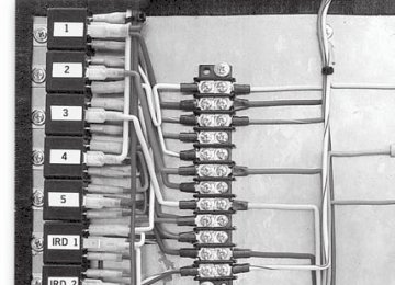
F-550 Circuit Board Assembly Ver. 1
10
11
IRD
IRD
IRD
12
13
14
15
16
17
18
19
20
21
22
23
24
25
26
F-550 circuit board located above driver F-550 circuit board located above driver
Krystal Enterprises
96
F-550 Circuit Board Ver 1 - Electrical Diagram
Relays
Circuit Breakers
Front A/C Board
Krystal Enterprises
9797
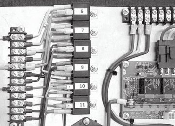
F-550 Circuit Board Assembly Ver. 2
12
13
14
15
16
17
18
19
20
21
22
23
24
25
26
27
28
29
30
F-550 circuit board located above driver
Krystal Enterprises
98
F-550 Circuit Board Ver 2 - Electrical Diagram
Relays
Circuit Breakers
Front A/C Board
Rear A/C Board
Krystal Enterprises
9999
E-450 & F-550 Modular Circuit Board Assembly Ver. 3
10
11
12
13
14
15
16
17
18
19
20
21
22
23
24
25
26
27
28
29
30
31
32
33
34
100
Krystal Enterprises
E-450 & F-550 Modular Circuit Board Assembly Ver. 3 Legend
Low Side Modular Switching Unit
Interior Lights - 15 amp fuse-max Interior Lights - 15 amp fuse-max
2 Door - 10 amp fuse-max 3 Heat Valve - 15 amp fuse-max 4 Spare - 10 amp fuse-max 7 Heater Fan Relay-HIGH 8 Heater Fan Relay-LOW 9 High Idle Relay 10 Door Interlock Relay 11 Rear Condenser Relay 12 Reading Lights- 15 amp fuse-max 13 Reading Lights- 15 amp fuse-max 14 Clearance Lights- 10 amp fuse-max 15 Clearance Lights- 10 amp fuse-max 16 Spare- 15 amp fuse-max 17 High Side Modular Switching Unit
18 Power Solenoid 19 Step- 25 amp fuse-max, 12 ga Red #260
20 Luggage Light- 10 amp fuse-max, 16 ga Red #320
21 To High Side Module- 3 amp fuse-max, 16 ga Red 22 To Panel LED- 3 amp fuse-max, 18 ga Red/Wht 23 Battery Fuse Block Module 24 Rear Step IGN-15 amp fuse-max, 16 ga Purple #280
25 Air Comp. IGN-15 amp fuse-max, 16 ga Purple #280
26 Heater Fan-HIGH, 15 amp fuse-max, 14 ga Red/Blk 27 Heater Fan-LOW, 10 amp fuse-max, 14 ga Yell/Red 28 Heater Relay Coil, 3 amp fuse-max, 18 ga Red 29 Ignition Fuse Block Module 30 High Idle- 7.5 amp fuse-max, 14 ga Org/Blk 31 Television- 10 amp fuse-max, 14 ga Org/Yell 32 Switch Panel IGN- 15 amp fuse-max, 16 ga Purple #280
33 Air Compressor Circuit Breaker 34 Five (5) Minute Light TimerSee detailed diagrams of items 1 & 17
( Low/High Side Switching Modules) on pages 102-103
Krystal Enterprises
101101
E-450 & F-550 LOW SIDE RELAY SWITCHING MODULE Ver. 3
SPARE FUSES
5 RELAY MODULE
Low Side Switching
INTELLITEC FUSE BLOCK
6 Pin Connector
5 Pin Connector
102
Krystal Enterprises
PIN
6 P I N C O N N E C T O R
Door Switch- 18 Ga Wht (to 5 min timer 18 ga Wht/Blk)
To Door- 16 Ga Blu/Wht #420C
Heat Valve Trigger- 18 Ga Grn/Blk
Heat Valve- 14 Ga Grn #400
Coil #3- Not Used
Output #3- Not Used
PIN
5 P I N C O N N E C T O R
To Interior Light Switch- 18 Ga Yel (to 5 min. timer+side- 18 Ga Yel/Blk with Diode)
Interior Lights- 14 Ga Yel- #350#B
To Interior Light Switch- 18 Ga Yel
Interior LIghts- 14 Ga Yel- - #350#A
Coil Common- 16 Ga Red- Battery- To Pin #1 On Fuse Block
To Battery- 8 Ga Red
E-450 & F-550 HIGH SIDE RELAY SWITCHING MODULE Ver. 3
SPARE FUSES
5 RELAY MODULE
High Side Switching
INTELLITEC FUSE BLOCK
6 Pin Connector
5 Pin Connector
PIN
6 P I N C O N N E C T O R
From Reading Light- 18 Ga Wht/Pupl
To Reading Lights #D- 16 Ga Org #700
Jumper from Pin#1- 18 Ga Wht/Pupl
To Reading Lights #E- 14 Ga Org #700
Clearance Lights #F- 16 Ga Brn/Wht #230
Clearance Lights #G- 14 ga Brn #230
PIN
5 P I N C O N N E C T O R
Clearance Lights-Jumper-16 Ga Brn/Wht #230
Clearance Lights #H- 14 Ga Brn #230
Not Used
Not Used
Coil Common- 16 Ga Wht
To Battery- 8 Ga Red