- 2001 Ford E 250 Owners Manuals
- Ford E 250 Owners Manuals
- 2003 Ford E 250 Owners Manuals
- Ford E 250 Owners Manuals
- 2012 Ford E 250 Owners Manuals
- Ford E 250 Owners Manuals
- 2002 Ford E 250 Owners Manuals
- Ford E 250 Owners Manuals
- 2006 Ford E 250 Owners Manuals
- Ford E 250 Owners Manuals
- 2009 Ford E 250 Owners Manuals
- Ford E 250 Owners Manuals
- 2007 Ford E 250 Owners Manuals
- Ford E 250 Owners Manuals
- 2010 Ford E 250 Owners Manuals
- Ford E 250 Owners Manuals
- 2004 Ford E 250 Owners Manuals
- Ford E 250 Owners Manuals
- 2008 Ford E 250 Owners Manuals
- Ford E 250 Owners Manuals
- 2011 Ford E 250 Owners Manuals
- Ford E 250 Owners Manuals
- 2005 Ford E 250 Owners Manuals
- Ford E 250 Owners Manuals
- Download PDF Manual
-
USA (fus)
Tires, Wheels and Loading
When inflating your tires When putting air into your tires (such as at a gas station or in your garage), the Tire Pressure Monitoring System may not respond immediately to the air added to your tires. It may take up to two minutes of driving over 20 mph (32 km/h) for the light to turn OFF after you have filled your tires to the recommended inflation pressure. How temperature affects your tire pressure The Tire Pressure Monitoring System (TPMS) monitors tire pressure in each pneumatic tire. While driving in a normal manner, a typical passenger tire inflation pressure may increase approximately 2 to 4 psi (14 to 28 kPa) from a cold start situation. If the vehicle is stationary over night with the outside temperature significantly lower than the daytime temperature, the tire pressure may decrease approximately 3 psi (20.7 kPa) for a drop of 30° F (16.6° C) in ambient temperature. This lower pressure value may be detected by the TPMS as being significantly lower than the recommended inflation pressure and activate the TPMS warning for low tire pressure. If the low tire pressure warning light is ON, visually check each tire to verify that no tire is flat. If one or more tires are flat, repair as necessary. Check air pressure in the road tires. If any tire is under-inflated, carefully drive the vehicle to the nearest location where air can be added to the tires. Inflate all the tires to the recommended inflation pressure.
TPMS reset procedure (if applicable) The TPMS reset tool is ONLY provided for vehicles with different front and rear tire pressures. The TPMS reset procedure needs to be performed after tire rotation only on these vehicles.
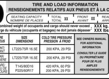
WARNING: To determine if your vehicle has different recommended pressures for the front and rear tires, refer to the Safety Compliance Certification Label or Tire Label which is located on the B-Pillar or the edge of the driver’s door. See Vehicle Loading in this chapter for more information.
Overview To provide the vehicle’s load carrying capability, some trucks require different recommended tire pressures in the front tires as compared to the rear tires. The Tire Pressure Monitoring System (TPMS) equipped on these vehicles is designed to illuminate the Low Tire Pressure Warning indicator at two different pressures; one for the front tires and one for the rear tires.
164
2009 Econoline (eco) Owners Guide, 2nd Printing USA (fus)
Tires, Wheels and Loading
Since tires need to be rotated to provide consistent performance and maximum tire life, the Tire Pressure Monitoring System needs to know when the tires are rotated to determine which set of tires are on the front and which are on the rear. With this information, the system can detect and properly warn of low tire pressures.
WARNING: Always perform the TPMS reset procedure after tire rotation when recommended pressures are different for the front
and rear tires.
TPMS reset tool A special TPMS reset tool to reset your TPMS after tire rotation is provided with vehicles that have different front and rear tire pressures. The tool is located with your Owner’s Guide materials. Please take the tool with the provided Velcro威 strip on the back and mount it in the bottom right corner of your Owner’s Guide case (as shown) for safe keeping.
If you find that the reset tool was not provided when delivered, has been lost or no longer functions (the battery is not replaceable), please contact your authorized dealer as soon as possible to obtain a replacement. To verify that your TPMS reset tool is working, press and release the button on the center of the TPMS tool. The red light should illuminate and remain on for approximately five (5) seconds. If the light does not illuminate, the tool needs to be replaced. TPMS reset tips: • To reduce the chances of interference from another vehicle, TPMS reset should be performed at least three feet (one meter) away from another Ford Motor Company vehicle undergoing the TPMS reset procedure at the same time. • Do not wait more than two (2) minutes between resetting each tire sensor or the system will timeout and the entire procedure will have to be repeated on all four wheels.
• A double horn chirp indicates the need to repeat the procedure.
165
2009 Econoline (eco) Owners Guide, 2nd Printing USA (fus)
Tires, Wheels and Loading
TPMS reset procedure It is recommended that you read the entire procedure before attempting. Note: To enter the reset mode, Steps 1–6 MUST be completed within 60 seconds. 1. Place the ignition in the off position and keep the key in the ignition. 2. Press and release the brake pedal.
3. Cycle the ignition from off to on three (3) times ending in the on position—DO NOT start the engine.
4. Press and hold the brake pedal for two (2) seconds, then release.
166
2009 Econoline (eco) Owners Guide, 2nd Printing USA (fus)
Tires, Wheels and Loading
5. Turn the ignition to off—DO NOT remove the key.
6. Cycle the ignition from off to on three (3) times ending in on. DO NOT start the engine. If the reset mode has been entered successfully, the horn will sound will flash and the message center will once, the TPMS indicator display TRAIN LEFT FRONT TIRE. If after repeated attempts to enter the reset mode, the horn does not does not flash and the message center sound, the TPMS indicator does not display TRAIN LEFT FRONT TIRE, contact your authorized dealer as soon as possible. 7. Train the TPMS sensors in the tires using the following TPMS reset sequence starting with the left front tire in the following clockwise order:
167
2009 Econoline (eco) Owners Guide, 2nd Printing USA (fus)
Tires, Wheels and Loading
1. Left front tire (Front driver’s side) 2. Right front tire (Front passenger’s side) 3. Right rear tire (Rear passenger’s side) 4. Left rear tire (Rear driver’s side)
8. Left front tire: Place the TPMS reset tool against the left front tire where the tire meets the rim, opposite from the valve stem (1) as shown. This is where the sensor is located inside the rim. The tool needs to be held against the tire sidewall opposite the valve stem as illustrated with the arrow on the tool pointing towards the rim; do not use the tool with the arrow pointing away from the rim as it may not activate the sensor. 9. Press and release the green button and hold the tool to the tire sidewall until the horn sounds. The red light on the TPMS reset tool will illuminate while the tool is active. The horn will sound once within 10 seconds to indicate the process was successful.
168
2009 Econoline (eco) Owners Guide, 2nd Printing USA (fus)
Tires, Wheels and Loading
Note: • If a double horn chirp is heard, repeat the procedure. If a single horn
chirp is not heard, move the vehicle to rotate the wheels at least a 1⁄4-turn and repeat the procedure starting with Step 1.
• If a double horn chirp is heard even after the wheels were
repositioned, contact your authorized dealer as soon as possible. 10. Perform Steps 8 and 9 on the right front tire, right rear tire and finally the left rear tire. Training is complete after the horn sounds for the last tire trained (left rear tire) and the message center displays: TRAINING COMPLETE. Turn the ignition to off. If two short horn beeps are heard, the reset procedure was unsuccessful and must be repeated. If after repeating the procedure and two short beeps are heard when the ignition is turned to off, contact your authorized dealer as soon as possible.
SNOW TIRES AND CHAINS
WARNING: Snow tires must be the same size, load index, speed rating as those originally provided by Ford. Use of any tire or
wheel not recommended by Ford can affect the safety and performance of your vehicle, which could result in an increased risk of loss of vehicle control, vehicle rollover, personal injury and death. Additionally, the use of non-recommended tires and wheels could cause steering, suspension, axle or transfer case/power transfer unit failure.
The tires on your vehicle have all weather treads to provide traction in rain and snow. However, in some climates, you may need to use snow tires and chains. If you need to use chains, it is recommended that steel wheels (of the same size and specifications) be used, as chains may chip aluminum wheels.
169
2009 Econoline (eco) Owners Guide, 2nd Printing USA (fus)
Tires, Wheels and Loading
Follow these guidelines when using snow tires and chains: • Use only SAE Class S chains. • Install chains securely, verifying that the chains do not touch any • Drive cautiously. If you hear the chains rub or bang against your
wiring, brake lines or fuel lines.
vehicle, stop and re-tighten the chains. If this does not work, remove the chains to prevent damage to your vehicle.
• If possible, avoid fully loading your vehicle. • Remove the tire chains when they are no longer needed. Do not use • The suspension insulation and bumpers will help prevent vehicle damage. Do not remove these components from your vehicle when using snow tires and chains.
tire chains on dry roads.
VEHICLE LOADING – WITH AND WITHOUT A TRAILER This section will guide you in the proper loading of your vehicle and/or trailer, to keep your loaded vehicle weight within its design rating capability, with or without a trailer. Properly loading your vehicle will provide maximum return of vehicle design performance. Before loading your vehicle, familiarize yourself with the following terms for determining your vehicle’s weight ratings, with or without a trailer, from the vehicle’s Tire Label or Safety Compliance Certification Label: Base Curb Weight – is the weight of the vehicle including a full tank of fuel and all standard equipment. It does not include passengers, cargo, or optional equipment. Vehicle Curb Weight – is the weight of your new vehicle when you picked it up from your authorized dealer plus any aftermarket equipment.
170
2009 Econoline (eco) Owners Guide, 2nd Printing USA (fus)
Tires, Wheels and Loading
Payload – is the combined weight of cargo and passengers that the vehicle is carrying. The maximum payload for your vehicle can be found on the Tire Label on the B-Pillar or the edge of the driver’s door (vehicles exported outside the US and Canada may not have a Tire Label). Look for “THE COMBINED WEIGHT OF OCCUPANTS AND CARGO SHOULD NEVER EXCEED XXX kg OR XXX lb.” for maximum payload. The payload listed on the Tire Label is the maximum payload for the vehicle as built by the assembly plant. If any aftermarket or authorized-dealer installed equipment has been installed on the vehicle, the weight of the equipment must be subtracted from the payload listed on the Tire Label in order to determine the new payload.
WARNING: The appropriate loading capacity of your vehicle can be limited either by volume capacity (how much space is
available) or by payload capacity (how much weight the vehicle should carry). Once you have reached the maximum payload of your vehicle, do not add more cargo, even if there is space available. Overloading or improperly loading your vehicle can contribute to loss of vehicle control and vehicle rollover.
171
2009 Econoline (eco) Owners Guide, 2nd Printing USA (fus)
Tires, Wheels and Loading
Example only:
Cargo Weight – includes all weight added to the Base Curb Weight, including cargo and optional equipment. When towing, trailer tongue load or king pin weight is also part of cargo weight. GAW (Gross Axle Weight) – is the total weight placed on each axle (front and rear) – including vehicle curb weight and all payload.
172
2009 Econoline (eco) Owners Guide, 2nd Printing USA (fus)
Tires, Wheels and Loading
GAWR (Gross Axle Weight Rating) – is the maximum allowable weight that can be carried by a single axle (front or rear). These numbers are shown on the Safety Compliance Certification Label located on the B-Pillar or the edge of the driver’s door. The total load on each axle must never exceed its GAWR. Note: For trailer towing information refer to Trailer towing found in this chapter or the RV and Trailer Towing Guide provided by your authorized dealer.
GVW (Gross Vehicle Weight) – is the Vehicle Curb Weight + cargo + passengers.
GVWR (Gross Vehicle Weight Rating) – is the maximum allowable weight of the fully loaded vehicle (including all options, equipment, passengers and cargo). The GVWR is shown on the Safety Compliance Certification Label located on the B-Pillar or the edge of the driver’s door. The GVW must never exceed the GVWR.
173
2009 Econoline (eco) Owners Guide, 2nd Printing USA (fus)
Tires, Wheels and Loading
WARNING: Exceeding the Safety Compliance Certification Label vehicle weight rating limits could result in substandard vehicle
handling or performance, engine, transmission and/or structural damage, serious damage to the vehicle, loss of control and personal injury.
GCW (Gross Combined Weight) – is the weight of the loaded vehicle (GVW) plus the weight of the fully loaded trailer. GCWR (Gross Combined Weight Rating) – is the maximum allowable weight of the vehicle and the loaded trailer – including all cargo and passengers – that the vehicle can handle without risking damage. (Important: The towing vehicle’s braking system is rated for operation at GVWR, not at GCWR.) Separate functional brakes should be used for safe control of towed vehicles and for trailers where the GCW of the towing vehicle plus the trailer exceed the GVWR of the towing vehicle. The GCW must never exceed the GCWR. Maximum Loaded Trailer Weight – is the highest possible weight of a fully loaded trailer the vehicle can tow. It assumes a vehicle with only mandatory options, no cargo (internal or external), a tongue load of 10–15% (conventional trailer) or king pin weight of 15–25% (fifth wheel trailer), and driver only (150 lb. [68 kg]). Consult your authorized dealer (or the RV and Trailer Towing Guide provided by your authorized dealer) for more detailed information. Tongue Load or Fifth Wheel King Pin Weight – refers to the amount of the weight that a trailer pushes down on a trailer hitch. Examples: For a 5,000 lb. (2,268 kg) conventional trailer, multiply 5,000
by 0.10 and 0.15 to obtain a proper tongue load range of 500 to 750 lb. (227 to 340 kg). For an 11,500 lb. (5,216 kg) fifth wheel trailer, multiply by 0.15 and 0.25 to obtain a proper king pin load range of 1,725 to 2,875 lb. (782 to 1,304 kg)WARNING: Do not exceed the GVWR or the GAWR specified on the Safety Compliance Certification Label.
174
2009 Econoline (eco) Owners Guide, 2nd Printing USA (fus)
Tires, Wheels and Loading
WARNING: Do not use replacement tires with lower load carrying capacities than the original tires because they may
lower the vehicle’s GVWR and GAWR limitations. Replacement tires with a higher limit than the original tires do not increase the GVWR and GAWR limitations.
WARNING: Exceeding any vehicle weight rating limitation could result in serious damage to the vehicle and/or personal injury.
Steps for determining the correct load limit: 1. Locate the statement “The combined weight of occupants and cargo should never exceed XXX kg or XXX lb.” on your vehicle’s placard. 2. Determine the combined weight of the driver and passengers that will be riding in your vehicle. 3. Subtract the combined weight of the driver and passengers from XXX kg or XXX lb. 4. The resulting figure equals the available amount of cargo and luggage load capacity. For example, if the “XXX” amount equals 1,400 lb. and there will be five 150 lb. passengers in your vehicle, the amount of available cargo and luggage load capacity is 650 lb. (1400-750 (5 x 150) = 650 lb.). In metric units (635-340 (5 x 68) = 295 kg.) 5. Determine the combined weight of luggage and cargo being loaded on the vehicle. That weight may not safely exceed the available cargo and luggage load capacity calculated in Step 4. 6. If your vehicle will be towing a trailer, load from your trailer will be transferred to your vehicle. Consult this manual to determine how this reduces the available cargo and luggage load capacity of your vehicle. The following gives you a few examples on how to calculate the available amount of cargo and luggage load capacity: • Another example for your vehicle with 1,400 lb. (635 kg) of cargo and luggage capacity. You decide to go golfing. Is there enough load capacity to carry you, 4 of your friends and all the golf bags? You and four friends average 220 lb. (99 kg) each and the golf bags weigh approximately 30 lb. (13.5 kg) each. The calculation would be: 1400 - (5 x 220) - (5 x 30) = 1400 - 1100 - 150 = 150 lb. Yes, you have enough load capacity in your vehicle to transport four friends and your golf bags. In metric units, the calculation would be: 635 kg - (5 x 99 kg) - (5 x 13.5 kg) = 635 - 495 - 67.5 = 72.5 kg.
175
2009 Econoline (eco) Owners Guide, 2nd Printing USA (fus)
Tires, Wheels and Loading • A final example for your vehicle with 1,400 lb. (635 kg) of cargo and luggage capacity. You and one of your friends decide to pick up cement from the local home improvement store to finish that patio you have been planning for the past 2 years. Measuring the inside of the vehicle with the rear seat folded down, you have room for 12-100 lb. (45 kg) bags of cement. Do you have enough load capacity to transport the cement to your home? If you and your friend each weigh 220 lb. (99 kg), the calculation would be: 1400 - (2 x 220) - (12
x 100) = 1400 - 440 - 1200 = - 240 lb. No, you do not have enough cargo capacity to carry that much weight. In metric units, the calculation would be: 635 kg - (2 x 99 kg) - (12 x 45 kg) = 635 - 198 - 540 = -103 kg. You will need to reduce the load weight by at least 240 lb. (104 kg). If you remove 3-100 lb. (45 kg) cement bags, then the load calculation would be: 1400 - (2 x 220) - (9 x 100) = 1400 - 440 - 900 = 60 lb. Now you have the load capacity to transport the cement and your friend home. In metric units, the calculation would be: 635 kg - (2 x 99 kg) - (9 x 45 kg) = 635 - 198 - 405 = 32 kg.The above calculations also assume that the loads are positioned in your vehicle in a manner that does not overload the Front or the Rear Gross Axle Weight Rating specified for your vehicle on the Safety Compliance Certification Label found on the edge of the driver’s door.
Special loading instructions for owners of pickup trucks and utility-type vehicles
WARNING: For important information regarding safe operation of this type of vehicle, see the Preparing to drive your vehicle
section in the Driving chapter of this Owner’s Guide.
WARNING: Loaded vehicles may handle differently than unloaded vehicles. Extra precautions, such as slower speeds and
increased stopping distance, should be taken when driving a heavily loaded vehicle.
Your vehicle can haul more cargo and people than most passenger cars. Depending upon the type and placement of the load, hauling cargo and people may raise the center of gravity of the vehicle.
176
2009 Econoline (eco) Owners Guide, 2nd Printing USA (fus)
Tires, Wheels and Loading
TRAILER TOWING Refer to 6.0 and 6.4 Liter Power Stroke Direct Injection Turbo Diesel Owner’s Guide Supplement for Diesel engine towing information. Your vehicle may tow a class I, II or III trailer, provided the maximum trailer weight is less than or equal to the maximum trailer weight listed for your engine and rear axle ratio on the following charts.
GCWR (Gross Combined Weight Rating)/Trailer Weights
Engine
Rear axle ratio
Maximum GCWR - lb.
(kg)
Maximum
Loaded
Trailer Weight
- lb. (kg)
Maximum
frontal area of
trailer - ft2
(m2)
E-150 Regular/RV Van (8520 GVWR)
4.6L
4.6L
3.73
4.10
11500
(5216) 12000
(5443)6000 (2722)
60 (5.52)
6500 (2948)
60 (5.52)
E-150 Regular Wagon (7/8 Passenger) (8520 GVWR)
4.6L
4.6L
5.4L
5.4L
4.6L
4.6L
3.73
4.10
11500
(5216) 12000
(5443)5500 (2495)
60 (5.52)
6000 (2722)
60 (5.52)
E-150 Regular/RV Van (8600 GVWR)
3.73
4.10
13000
(5897) 13000
(5897)7400 (3357)
60 (5.52)
7400 (3357)
60 (5.52)
E-150 Extended Van (8600 GVWR)
3.73
4.10
11500
(5216) 12000
(5443)5800 (2631)
60 (5.52)
6300 (2858)
60 (5.52)
177
2009 Econoline (eco) Owners Guide, 2nd Printing USA (fus)
Tires, Wheels and Loading
GCWR (Gross Combined Weight Rating)/Trailer Weights
Engine
Rear axle ratio
Maximum GCWR - lb.
(kg)
Maximum
Loaded
Trailer Weight
- lb. (kg)
Maximum
frontal area of
trailer - ft2
(m2)
E-150 Extended Van (8600 GVWR)
5.4L
5.4L
3.73
4.10
13000
(5897) 13000
(5897)7300 (3311)
60 (5.52)
7300 (3311)
60 (5.52)
E-150 Regular Wagon (7/8 Passenger) (8600 GVWR)
5.4L
5.4L
4.6L
4.6L
4.6L
4.6L
5.4L
5.4L
3.73
4.10
13000
(5897) 13000
(5897)7000 (3175)
60 (5.52)
7000 (3175)
60 (5.52)
E-250 Regular/RV Van (8900 GVWR)
3.73
4.10
11500
(5216) 12000
(5443)5900 (2676)
60 (5.52)
6400 (2903)
60 (5.52)
E-250 Extended/RV Van (8900 GVWR)
3.73
4.10
11500
(5216) 12000
(5443)5800 (2631)
60 (5.52)
6300 (2858)
60 (5.52)
E-250 Regular/RV Van (9000 GVWR)
3.73
4.10
13000
(5896) 13000
(5896)7400 (3357)
60 (5.52)
7400 (3357)
60 (5.52)
E-250 Cutaway (138” wheelbase, single rear wheel) (8600
GVWR)
4.6L
4.10
12000
(5443)7500 (3402)
60 (5.52)
178
2009 Econoline (eco) Owners Guide, 2nd Printing USA (fus)
Tires, Wheels and Loading
GCWR (Gross Combined Weight Rating)/Trailer Weights
Engine
Rear axle ratio
Maximum GCWR - lb.
(kg)
Maximum
Loaded
Trailer Weight
- lb. (kg)
Maximum
frontal area of
trailer - ft2
(m2)
5.4L
5.4L
5.4L
5.4L
6.8L
6.8L
5.4L
5.4L
6.8L
6.8L
E-250 Extended/RV Van (9000 GVWR)
3.73
4.10
13000
(5896) 13000
(5896)7300 (3311)
60 (5.52)
7300 (3311)
60 (5.52)
E-350 Regular/RV Van (9500 GVWR)
3.73
4.10
3.73
4.10
13000
(5897) 13000
(5897) 15000
(6804) 18500
(8391)7300 (3311)
60 (5.52)
7300 (3311)
60 (5.52)
9100 (4128)
60 (5.52)
10000 (4536)
60 (5.52)
E-350 Extended/RV Van (9500 GVWR)
3.73
4.10
3.73
4.10
13000
(5897) 13000
(5897) 15000
(6804) 18500
(8391)7200 (3266)
60 (5.52)
7200 (3266)
60 (5.52)
9000 (4082)
60 (5.52)
10000 (4536)
60 (5.52)
E-350 Regular Wagon (11/12 Passenger) (8800 GVWR)
5.4L
5.4L
3.73
4.10
13000
(5897) 13000
(5897)6700 (3039)
60 (5.52)
6700 (3039)
60 (5.52)
179
2009 Econoline (eco) Owners Guide, 2nd Printing USA (fus)
Tires, Wheels and Loading
GCWR (Gross Combined Weight Rating)/Trailer Weights
Engine
Rear axle ratio
Maximum GCWR - lb.
(kg)
Maximum
Loaded
Trailer Weight
Maximum
frontal area of
trailer - ft2
(m2) E-350 Regular Wagon (11/12 Passenger) (8700 GVWR)
- lb. (kg)
6.8L
6.8L
3.73
4.10
15000
(6804) 18500
(8391)8500 (3856)
60 (5.52)
10000 (4536)
60 (5.52)
E-350 Extended Wagon (11 Passenger) (9300 GVWR)
5.4L
5.4L
3.73
4.10
13000
(5897) 13000
(5897)6500 (2948)
60 (5.52)
6500 (2948)
60 (5.52)
E-350 Extended Wagon (11 Passenger) (9500 GVWR)
6.8L
6.8L
3.73
4.10
15000
(6804) 18500
(8391)8300 (3765 )
60 (5.52)
10000 (4536)
60 (5.52)
E-350 Extended Wagon (14/15 Passenger) (9100 GVWR)
5.4L
5.4L
3.73
4.10
13000
(5897) 13000
(5897)6300 (2858)
60 (5.52)
6300 (2858)
60 (5.52)
E-350 Extended Wagon (14/15 Passenger) (9300 GVWR)
6.8L
6.8L
3.73
4.10
15000
(6804) 18500
(8391)8100 (3674)
60 (5.52)
10000 (4536)
60 (5.52)
180
2009 Econoline (eco) Owners Guide, 2nd Printing USA (fus)
Tires, Wheels and Loading
GCWR (Gross Combined Weight Rating)/Trailer Weights
Engine
Rear axle ratio
Maximum GCWR - lb.
(kg)
Maximum
Loaded
Trailer Weight
- lb. (kg)
Maximum
frontal area of
trailer - ft2
(m2)
E-350 Cutaway (138” wheelbase, single rear wheel) (9600
GVWR)
5.4L
6.8L
4.10
4.10
13000
(5897) 18500
(8391)8000 (3629)
60 (5.52)
10000 (4536)
60 (5.52)
E-350 Extended Cutaway (138” wheelbase, single rear wheel)
(9600 GVWR)
5.4L
4.10
10600
(4808)5700 (2585)
60 (5.52)
E-350 Cutaway (138” wheelbase, dual rear wheel) (10000
GVWR)
5.4L
6.8L
4.10
4.10
13000
(5897) 18500
(8391)7800 (3538)
60 (5.52)
10000 (4536)
60 (5.52)
E-350 Cutaway (158” wheelbase, dual rear wheel) (10000
GVWR)
5.4L
6.8L
4.10
4.10
13000
(5897) 18500
(8391)7700 (3493)
60 (5.52)
10000 (4536)
60 (5.52)
E-350 Cutaway (138” wheelbase, dual rear wheel) (11500
GVWR)
5.4L
6.8L
4.10
4.10
13000
(5897) 18500
(8391)7800 (3538)
60 (5.52)
10000 (4536)
60 (5.52)
181
2009 Econoline (eco) Owners Guide, 2nd Printing USA (fus)
Tires, Wheels and Loading
GCWR (Gross Combined Weight Rating)/Trailer Weights
Engine
Rear axle ratio
Maximum GCWR - lb.
(kg)
Maximum
Loaded
Trailer Weight
- lb. (kg)
Maximum
frontal area of
trailer - ft2
(m2)
E-350 Cutaway (158” wheelbase, dual rear wheel) (11500
GVWR)
5.4L
6.8L
4.10
4.10
13000
(5897) 18500
(8391)7700 (3493)
60 (5.52)
10000 (4536)
60 (5.52)
E-350 Cutaway (158” wheelbase, dual rear wheel) (12500
GVWR)
5.4L
6.8L
4.10
4.10
13000
(5897) 18500
(8391)7700 (3493)
60 (5.52)
10000 (4536)
60 (5.52)
E-350 Cutaway (176” wheelbase, dual rear wheel) (10000
GVWR)
5.4L
6.8L
4.10
4.10
13000
(5897) 18500
(8391)7700 (3493)
60 (5.52)
10000 (4536)
60 (5.52)
E-350 Cutaway (176” wheelbase, dual rear wheel) (12500
GVWR)
5.4L
6.8L
4.10
4.10
13000
(5897) 18500
(8391)7700 (3493)
60 (5.52)
10000 (4536)
60 (5.52)
E-350 Stripped Chassis (138” wheelbase, single rear wheel)
(9000 GVWR)
5.4L
5.4L
3.73
4.10
13000
(5897) 13000
(5897)8700 (3946)
60 (5.52)
8700 (3946)
60 (5.52)
182
2009 Econoline (eco) Owners Guide, 2nd Printing USA (fus)
Tires, Wheels and Loading
GCWR (Gross Combined Weight Rating)/Trailer Weights
Engine
Rear axle ratio
Maximum GCWR - lb.
(kg)
Maximum
Loaded
Trailer Weight
- lb. (kg)
Maximum
frontal area of
trailer - ft2
(m2)
E-350 Stripped Chassis (158” wheelbase, single rear wheel)
(9600 GVWR)
5.4L
5.4L
3.73
4.10
13000
(5897) 13000
(5897)8600 (3901)
60 (5.52)
8600 (3901)
60 (5.52)
E-350 Stripped Chassis (138” wheelbase, dual rear wheel)
(10000 GVWR)
5.4L
6.8L
4.10
4.10
13000
(5897) 18500
(8391)8400 (3810)
60 (5.52)
10000 (4536)
60 (5.52)
E-350 Stripped Chassis (138” wheelbase, dual rear wheel)
(11500 GVWR)
5.4L
6.8L
4.10
4.10
13000
(5897) 18500
(8391)8400 (3810)
60 (5.52)
10000 (4536)
60 (5.52)
E-350 Stripped Chassis (158” wheelbase, dual rear wheel)
(10000 GVWR)
5.4L
6.8L
4.10
4.10
13000
(5897) 18500
(8391)8300 (3765)
60 (5.52)
10000 (4536)
60 (5.52)
E-350 Stripped Chassis (158” wheelbase, dual rear wheel)
(12500 GVWR)
5.4L
6.8L
4.10
4.10
13000
(5897) 18500
(8391)8300 (3765)
60 (5.52)
10000 (4536)
60 (5.52)
183
2009 Econoline (eco) Owners Guide, 2nd Printing USA (fus)
Tires, Wheels and Loading
GCWR (Gross Combined Weight Rating)/Trailer Weights
Engine
Rear axle ratio
Maximum GCWR - lb.
(kg)
Maximum
Loaded
Trailer Weight
- lb. (kg)
Maximum
frontal area of
trailer - ft2
(m2)
E-350 Stripped Chassis (176” wheelbase, dual rear wheel)
(10000 GVWR)
5.4L
6.8L
4.10
4.10
13000
(5897) 18500
(8391)8300 (3765)
60 (5.52)
10000 (4536)
60 (5.52)
E-350 Stripped Chassis (176” wheelbase, dual rear wheel)
(12500 GVWR)
5.4L
6.8L
4.10
4.10
13000
(5897) 18500
(8391)8300 (3765)
60 (5.52)
10000 (4536)
60 (5.52)
E-450 Cutaway (158” wheelbase, dual rear wheel) (14050
GVWR)
5.4L
4.56
14050
(6373)8400 (3810)
60 (5.52)
E-450 Cutaway (176” wheelbase, dual rear wheel) (14050
GVWR)
5.4L
4.56
14050
(6373)8400 (3810)
60 (5.52)
E-450 Cutaway (158” wheelbase, dual rear wheel) (14500
GVWR)
6.8L
4.56
20000
(9072)10000 (4536)
60 (5.52)
E-450 Cutaway (176” wheelbase, dual rear wheel) (14500
GVWR)
6.8L
4.56
20000
(9072)10000 (4536)
60 (5.52)
184
2009 Econoline (eco) Owners Guide, 2nd Printing USA (fus)
Tires, Wheels and Loading
GCWR (Gross Combined Weight Rating)/Trailer Weights
Engine
Rear axle ratio
Maximum GCWR - lb.
(kg)
Maximum
Loaded
Trailer Weight
- lb. (kg)
Maximum
frontal area of
trailer - ft2
(m2)
E-450 Stripped Chassis (158” wheelbase, dual rear wheel)
(14050 GVWR)
5.4L
4.56
14050
(6373)9200 (4173)
60 (5.52)
E-450 Stripped Chassis (176” wheelbase, dual rear wheel)
(14050 GVWR)
5.4L
4.56
14050
(6372)9100 (4128)
60 (5.52)
E-450 Stripped Chassis (158” wheelbase, dual rear wheel)
(14500 GVWR)
6.8L
4.56
20000
(9072)10000 (4536)
60 (5.52)
E-450 Stripped Chassis (176” wheelbase, dual rear wheel)
(14500 GVWR)
6.8L
4.56
20000
(9072)10000 (4536)
60 (5.52)
Maximum trailer weight for all cutaway (E-350 and E-450) vehicles must be calculated by subtracting the weight of the vehicle (including incomplete vehicle weight and payload which includes second unit body weight, cargo and passengers) from the GCW. Otherwise, maximum trailer weight is 10,000 lb. (4,536 kg). For high altitude operation reduce GCWR by 2% per 1,000 ft. (300 meters) elevation. To determine the maximum trailer weight designed for your particular vehicle as equipped, follow the section Vehicle loading earlier in this chapter. Your vehicle’s load capacity is designated by weight, not by volume, so you cannot necessarily use all available space when loading a vehicle. Distribute the load so that only 10–15% of the total is on the tongue. Tie down the load so that it does not shift and change the weight on the hitch.
185
2009 Econoline (eco) Owners Guide, 2nd Printing USA (fus)
Tires, Wheels and Loading
Towing a trailer places an additional load on your vehicle’s engine, transmission, axle, brakes, tires and suspension. Inspect these components carefully after any towing operation. Do not exceed trailer weight of 5,000 lb (2,268 kg) when towing with bumper only.
WARNING: Do not exceed the GVWR or the GAWR specified on the certification label.
WARNING: Towing trailers beyond the maximum recommended gross trailer weight exceeds the limit of the vehicle and could
result in engine damage, transmission damage, structural damage, loss of vehicle control, vehicle rollover and personal injury.
Preparing to tow Use the proper equipment for towing a trailer and make sure it is properly attached to your vehicle. Contact your authorized dealer or a reliable trailer dealer as soon as possible if you require assistance.
Hitches Do not use or install hitches that clamp onto the bumper or to the axle. Underbody hitches are acceptable if installed properly.
Safety chains Always connect the trailer’s safety chains to the frame or hook retainers of the vehicle hitch. To connect the trailer’s safety chains, cross the chains under the trailer tongue and allow slack for turning corners. If you use a rental trailer, follow the instructions that the rental agency gives to you. Do not attach safety chains to the bumper.
Trailer brakes Electric brakes and manual, automatic or surge-type trailer brakes are safe if installed properly and adjusted to the manufacturer’s specifications. The trailer brakes must meet local and Federal regulations.
186
2009 Econoline (eco) Owners Guide, 2nd Printing USA (fus)
Tires, Wheels and Loading
WARNING: Do not connect a trailer’s hydraulic brake system directly to your vehicle’s brake system. Your vehicle may not have enough braking power and your chances of having a collision greatly increase.
The braking system of the tow vehicle is rated for operation at the GVWR not GCWR. Integrated trailer brake controller (if equipped) Your vehicle may be equipped with a fully integrated electronic Trailer Brake Controller (TBC). When used properly, the TBC helps ensure smooth and effective trailer braking by powering the trailer’s electric brakes with a proportional output based on the towing vehicle’s brake pressure.
WARNING: The Ford TBC has only been verified to be compatible with trailers having electric-actuated drum brakes
(one to four axles) and not hydraulic surge or electric-over-hydraulic types. It is the responsibility of the customer to ensure that the trailer brakes are adjusted appropriately, functioning normally and all electric connections are properly made.
The TBC user interface consists of the following: 1. +/- (GAIN adjustment buttons): Pressing these buttons will adjust the TBC’s power output to the trailer brakes (in 0.5 increments). The GAIN setting can be increased to a maximum of 10.0 or decreased to a minimum of 0 (no trailer braking). Pressing and holding a button will raise or lower the setting continuously. The gain setting will display in the message center as follows: TBC GAIN = XX.X. The trailer brake controller (TBC) is designed to display three items of information in the instrument cluster message center. These are: gain setting, output bar graph, and trailer connectivity status. They will appear as follows in the message center. • TBC GAIN = XX.X NO TRAILER: The instrument cluster message
center will display the current gain setting during a given ignition cycle and when adjusting the gain. This message is also displayed
187
2009 Econoline (eco) Owners Guide, 2nd Printing USA (fus)
Tires, Wheels and Loading
during manual activation without a trailer connected or when gain adjustments are made with no trailer connected.
• TBC GAIN = XX.X OUTPUT = //////: When the vehicle’s brake pedal is pushed, or when the manual control is activated, bar indicators will illuminate in the instrument cluster message center to indicate the amount of power going to the trailer brakes relative to the brake pedal or manual control input. One bar indicates the least amount of output with six bars indicating maximum output. • TRAILER CONNECTED: This message is displayed when a correct
trailer wiring connection (a trailer with electric trailer brakes) has been sensed during a given ignition cycle.
• TRAILER DISCONNECTED: This message is displayed and accompanied by a single chime, when a trailer connection was determined and then a disconnection, either intentionally or unintentionally, has been sensed during a given ignition cycle. It is also displayed if a truck or trailer wiring fault occurs causing the trailer to appear disconnected. This message is also displayed during manual activation without a trailer connected.
2. Manual control lever: Slide the control lever to the left to activate power to the trailer’s electric brakes independent of the tow vehicle’s brakes (see the following Procedure for adjusting GAIN section for instructions on proper use of this feature). If the manual control is activated while the brake is also applied, the greater of the two inputs determines the power sent to the trailer brakes. • Stop Lamps: Activating the TBC manual control lever will illuminate both the trailer brake lamps and the tow vehicle brake lamps except the Center High-Mount Stop Lamp (presuming proper trailer electrical connection). Pressing the vehicle brake pedal will also illuminate both trailer and vehicle brake lamps. Procedure for adjusting GAIN: The GAIN setting is used to set the TBC for the specific towing condition and should be changed as towing conditions change. Changes to towing conditions include trailer load, vehicle load, road conditions and weather. The GAIN should be set to provide the maximum trailer braking assistance while ensuring the trailer wheels do not lock when braking. Locked trailer wheels may lead to trailer instability. Note: This should only be performed in a traffic free environment at speeds of approximately 20–25 mph (30–40 km/h).
188
2009 Econoline (eco) Owners Guide, 2nd Printing USA (fus)
Tires, Wheels and Loading
1. Make sure the trailer brakes are in good working condition, functioning normally, and properly adjusted. See your trailer dealer if necessary. 2. Hook up the trailer and make the electrical connections according to the trailer manufacturer’s instructions. 3. When a trailer with electric brakes is plugged in, the TRAILER CONNECTED message will display in the instrument cluster message center. 4. Use the GAIN adjustment (+/-) buttons to increase or decrease the GAIN setting to the desired starting point. A GAIN setting of 6.0 is a good starting point for heavier loads. 5. In a traffic-free environment, tow the trailer on a dry, level surface at a speed of 20–25 mph (30–40 km/h) and squeeze the manual control lever completely. 6. If the trailer wheels lock-up (indicated by squealing tires), reduce the GAIN setting; if the trailer wheels turn freely, increase the GAIN setting. Repeat Steps 5 and 6 until the GAIN setting is at a point just below trailer wheel lock-up. If towing a heavier trailer, trailer wheel lockup may not be attainable even with the maximum GAIN setting of 10. Explanation of instrument cluster warning messages: The TBC interacts with the instrument cluster message center to display the following messages: TRAILER BRAKE MODULE FAULT: This message is displayed and accompanied by a single chime, in response to faults sensed by the TBC. In the event this message is seen, please contact your authorized dealer as soon as possible for diagnosis and repair. The TBC may still function, but performance may be degraded. WIRING FAULT ON TRAILER: This message is displayed when a Short circuit on the electric brake output wire has occurred. If the WIRING FAULT ON TRAILER message is displayed and accompanied by a single chime, with no trailer connected, the problem is with the vehicle wiring from the TBC to the 7–pin connector in the bumper. If the message is only displayed with a trailer connected, the problem is related to the trailer wiring; consult your trailer dealer for assistance. This can be a short to ground (i.e., chaffed wire) or a short to voltage (i.e., pulled pin on trailer emergency break-away battery) or trailer brakes drawing too much current. Note: Your TBC can be diagnosed by your authorized dealer to determine exactly which trailer fault has occurred; however, if the fault is with the trailer this diagnosis is not covered under your Ford warranty.
189
2009 Econoline (eco) Owners Guide, 2nd Printing USA (fus)
Tires, Wheels and Loading
Points to Remember: • Remember to adjust gain setting before using the TBC for the first • Readjust GAIN setting on the TBC (according to procedure above)
time.
whenever road, weather and trailer or vehicle loading conditions change from those that existed when the gain was initially set. • The sliding lever on the TBC should be used only for manual
activation of trailer brakes to assist with proper adjustment of the GAIN. Misuse, such as application during trailer sway, could cause instability of trailer and/or tow vehicle.
• Avoid towing in adverse weather conditions. The TBC does not provide anti-lock control of the trailer wheels. Trailer wheels can lock-up on slippery surfaces, resulting in reduced stability of trailer and tow vehicle. • The TBC interacts with the brake system of the vehicle, including
ABS, in order to reduce the likelihood of trailer wheel lockup. Therefore, if these systems are not functioning properly the TBC may not function at full performance.
• When the vehicle is turned off, the TBC Output is disabled and the
display is shut down. Reactivation of the ignition from OFF to ON will awaken the TBC module.
• The TBC is only a factory or dealer installed item. Ford is not
responsible for warranty or performance of the TBC due to misuse or customer installation.
• Do not attempt removal of the TBC without consulting the
Workshop Manual. Damage to the unit may result.
Trailer lamps Trailer lamps are required on most towed vehicles. Make sure all running lights, brake lights, turn signals and hazard lights are working. Contact your authorized dealer or trailer rental agency for proper instructions and equipment for hooking up trailer lamps.
Using a step bumper (if equipped) The rear bumper is equipped with an integral hitch and only requires a ball with a one inch (25.4 mm) shank diameter. The bumper has a 5,000 lb (2,270 kg) trailer weight and 500 lb (227 kg) tongue weight capacity. If it is necessary to relocate the trailer hitch ball position, a frame-mounted trailer hitch must be installed.
190
2009 Econoline (eco) Owners Guide, 2nd Printing USA (fus)
Tires, Wheels and Loading
Driving while you tow When towing a trailer: • To ensure proper “break-in” of powertrain components, do not trailer • To ensure proper “break-in” of powertrain components during the first
tow during the first 1,000 miles (1,600 km) of a new vehicle.
in transmission cooling.
500 miles (800 km) of trailer towing, drive no faster than 70 mph (113 km/h) with no full throttle starts.
• Turn off the speed control. The speed control may shut off automatically when you are towing on long, steep grades. • Consult your local motor vehicle speed regulations for towing a trailer. • To eliminate excessive shifting, use a lower gear. This will also assist • Anticipate stops and brake gradually. When descending long, steep downhill grades, always use a lower gear to provide engine braking to save wear on brakes. Use Drive (Overdrive OFF) on moderately steep hills, Second (2) on steep hills, and First (1) on very steep hills. Do not apply your brakes continuously, as they may overheat and become less effective. Servicing after towing If you tow a trailer for long distances, your vehicle will require more frequent service intervals. Refer to your scheduled maintenance information for more information.
Trailer towing tips • Practice turning, stopping and backing up before starting on a trip to get the feel of the vehicle trailer combination. When turning, make wider turns so the trailer wheels will clear curbs and other obstacles.
• Allow more distance for stopping with a trailer attached. • The trailer tongue weight should be 10–15% of the loaded trailer • If you will be towing a trailer frequently in hot weather, hilly
weight.
conditions, at GCWR, or any combination of these factors, consider refilling your rear axle with synthetic gear lube if not already so equipped. Refer to the Maintenance and specifications chapter for the lubricant specification. Remember that regardless of the rear axle lube used, do not tow a trailer for the first 1,000 miles (1,600 km) of a new vehicle, and that the first 500 miles (800 km) of towing be done at no faster than 70 mph (113 km/h) with no full throttle starts.
191
2009 Econoline (eco) Owners Guide, 2nd Printing USA (fus)
Tires, Wheels and Loading • Do not tow a trailer for the first 500 miles (800 km) after changing • After you have traveled 50 miles (80 km), thoroughly check your • When stopped in traffic for long periods of time in hot weather, place
hitch, electrical connections and trailer wheel lug nuts.
the rear axle lube.
the gearshift in P (Park) and increase idle speed. This aids engine cooling and air conditioner efficiency. • Vehicles with trailers should not be parked on a grade. If you must
park on a grade, place wheel chocks under the trailer’s wheels.
Launching or retrieving a boat Disconnect the wiring to the trailer before backing the trailer into the water. Reconnect the wiring to the trailer after the trailer is removed from the water. When backing down a ramp during boat launching or retrieval: • do not allow the static water level to rise above the bottom edge of • do not allow waves to break higher than 6 inches (15 cm) above the
the rear bumper.
bottom edge of the rear bumper.
Exceeding these limits may allow water to enter vehicle components: • causing internal damage to the components. • affecting driveability, emissions and reliability. Replace the rear axle lubricant any time the axle has been submerged in water. Rear axle lubricant quantities are not to be checked or changed unless a leak is suspected or repair required.
RECREATIONAL TOWING Follow these guidelines if you have a need for recreational (RV) towing. An example of recreational towing would be towing your vehicle behind a motorhome. These guidelines are designed to ensure that your transmission is not damaged. All vehicles: Do not tow your vehicle with any wheels on the ground, as vehicle or transmission damage may occur. It is recommended to tow your vehicle with all four (4) wheels off the ground such as when using a car-hauling trailer. Otherwise, no recreational towing is permitted. In case of a roadside emergency with a disabled vehicle, see Wrecker towing in the Roadside Emergencies chapter.
192
2009 Econoline (eco) Owners Guide, 2nd Printing USA (fus)
STARTING
Driving
Positions of the ignition 1. Accessory — allows the electrical accessories such as the radio to operate while the engine is not running. 2. Lock — locks the automatic transmission gearshift lever and allows key removal. 3. Off — shuts off the engine and all accessories without locking the steering wheel. 4. On — all electrical circuits operational. Warning lights illuminated. Key position when driving. 5. Start — cranks the engine. Release the key as soon as the engine starts.
Preparing to start your vehicle Engine starting is controlled by the powertrain control system. This system meets all Canadian Interference-Causing Equipment standard requirements regulating the impulse electrical field strength of radio noise. When starting a fuel-injected engine, don’t press the accelerator before or during starting. Only use the accelerator when you have difficulty starting the engine. For more information on starting the vehicle, refer to Starting the engine in this chapter.
WARNING: Extended idling at high engine speeds can produce very high temperatures in the engine and exhaust system,
creating the risk of fire or other damage.
WARNING: Do not park, idle, or drive your vehicle in dry grass or other dry ground cover. The emission system heats up the
engine compartment and exhaust system, which can start a fire.
193
2009 Econoline (eco) Owners Guide, 2nd Printing USA (fus)
Driving
WARNING: Do not start your vehicle in a closed garage or in other enclosed areas. Exhaust fumes can be toxic. Always open
the garage door before you start the engine. See Guarding against exhaust fumes in this chapter for more instructions.
WARNING: If you smell exhaust fumes inside your vehicle, have your dealer inspect your vehicle immediately. Do not drive if you
smell exhaust fumes.
Important safety precautions When the engine starts, the idle RPM runs faster to warm the engine. If the engine idle speed does not slow down automatically, have the vehicle checked. If your vehicle is operated in a heavy snow storm or blowing snow conditions, the engine air induction may become partially clogged with snow and/or ice. If this occurs, the engine may experience a significant reduction in power output. At the earliest opportunity, clear all the snow and/or ice away from the air induction inlet. Before starting the vehicle: 1. Make sure all occupants buckle their safety belts. For more information on safety belts and their proper usage, refer to the Seating and Safety Restraints chapter. 2. Make sure the headlamps and electrical accessories are off. • Make sure the parking brake is
set.
• Make sure the gearshift is in P
(Park).
194
2009 Econoline (eco) Owners Guide, 2nd Printing USA (fus)
• Turn the key to 4 (on) without
turning the key to 5 (start).
Driving
Some warning lights will briefly illuminate. See Warning lights and chimes in the Instrument Cluster chapter for more information regarding the warning lights.
Starting the engine 1. Turn the key to 4 (on) without turning the key to 5 (start). 2. Turn the key to 5 (start), then release the key as soon as the engine starts. Excessive cranking could damage the starter.
Note: If the engine does not start within five seconds on the first try, turn the key to 3 (off), wait 10 seconds and try again. If the engine still fails to start, press the accelerator to the floor and try again; this will allow the engine to crank with the fuel shut off in case the engine is flooded with fuel. Cold weather starting (flexible fuel vehicles only) The starting characteristics of all grades of E85 ethanol make it unsuitable for use when ambient temperatures fall below 0°F (-18°C). Consult your fuel distributor for the availability of winter grade ethanol. As the outside temperature approaches freezing, ethanol fuel distributors should supply winter grade ethanol (same as with unleaded gasoline). If summer grade ethanol is used in cold weather conditions, 0°F to 32°F (-18°C to 0°C), you may experience increased cranking times, rough idle or hesitation until the engine has warmed up.
195
2009 Econoline (eco) Owners Guide, 2nd Printing USA (fus)
Driving
You may experience a decrease in peak performance when the engine is cold when operating on E85 ethanol. Do not crank the engine for more than 10 seconds at a time as starter damage may occur. If the engine fails to start, turn the key to off and wait 30 seconds before trying again. Do not use starting fluid such as ether in the air intake system. Such fluid could cause immediate explosive damage to the engine and possible personal injury. If you should experience cold weather starting problems on E85 ethanol, and neither an alternative brand of E85 ethanol nor an engine block heater is available, the addition of unleaded gasoline to your tank will improve cold starting performance. Your vehicle is designed to operate on E85 ethanol alone, unleaded gasoline alone, or any mixture of the two. See Choosing the right fuel in the Maintenance and Specifications chapter for more information on ethanol.
Guarding against exhaust fumes Carbon monoxide is present in exhaust fumes. Take precautions to avoid its dangerous effects.
WARNING: If you smell exhaust fumes inside your vehicle, have your dealer inspect your vehicle immediately. Do not drive if you
smell exhaust fumes.
Important ventilating information If the engine is idling while the vehicle is stopped for a long period of time, open the windows at least one inch (2.5 cm) or adjust the heating or air conditioning to bring in fresh air.
ENGINE BLOCK HEATER (IF EQUIPPED) An engine block heater warms the engine coolant which aids in starting and allows the heater/defroster system to respond quickly. If your vehicle is equipped with this system, your equipment includes a heater element which is installed in your engine block and a wire harness which allows the user to connect the system to a grounded 120 volt a/c electrical source. The block heater system is most effective when outdoor temperatures reach below 0°F (-18°C). For flexible fuel vehicles, if operating with E85 ethanol, an engine block heater must be used if ambient temperature is below 0°F (-18°C).
196
2009 Econoline (eco) Owners Guide, 2nd Printing USA (fus)
Driving
See Cold weather starting in the Driving chapter for more information on starting with ethanol.
WARNING: Failure to follow engine block heater instructions could result in property damage or physical injury.
WARNING: To reduce the risk of electrical shock, do not use your heater with ungrounded electrical systems or two-pronged
(cheater) adapters.
Prior to using the engine block heater, follow these recommendations for proper and safe operation: • For your safety, use an outdoor extension cord that is product certified by Underwriter’s Laboratory (UL) or Canadian Standards Association (CSA). Use only an extension cord that can be used outdoors, in cold temperatures, and is clearly marked ⬙Suitable for Use with Outdoor Appliances.⬙ Never use an indoor extension cord outdoors; it could result in an electric shock or fire hazard.
• Use a 16 gauge outdoor extension cord, minimum. • Use as short an extension cord as possible. • Do not use multiple extension cords. Instead, use one extension cord which is long enough to reach from the engine block heater cord to the outlet without stretching. • Make certain that the extension cord is in excellent condition (not patched or spliced). Store your extension cord indoors at temperatures above 32°F (0°C). Outdoor conditions can deteriorate extension cords over a period of time. • To reduce the risk of electrical shock, do not use your heater with ungrounded electrical systems or two pronged (cheater) adapters. Also ensure that the block heater, especially the cord, is in good condition before use.
• Make sure that when in operation, the extension cord plug /engine block heater cord plug connection is free and clear of water in order to prevent possible shock or fire. • Be sure that areas where the vehicle is parked are clean and clear of all combustibles such as petroleum products, dust, rags, paper and similar items.
• Be sure that the engine block heater, heater cord and extension cord
are solidly connected. A poor connection can cause the cord to
197
2009 Econoline (eco) Owners Guide, 2nd Printing USA (fus)
Driving
become very hot and may result in an electrical shock or fire. Be sure to check for heat anywhere in the electrical hookup once the system has been operating for approximately a half hour. • Finally, have the engine block heater system checked during your fall
tune-up to be sure it’s in good working order.
How to use the engine block heater Ensure the receptacle terminals are clean and dry prior to use. To clean them, use a dry cloth. Depending on the type of factory installed equipment, your engine block heater system may consume anywhere between 400 watts or 1000 watts of energy per hour. Your factory installed block heater system does not have a thermostat; however, maximum temperature is attained after approximately three hours of operation. Block heater operation longer than 3 hours will not improve system performance and will unnecessarily use additional electricity. Make sure system is unplugged and properly stowed before driving the vehicle. While not in use, make sure the protective cover seals the prongs of the engine block heater cord plug.
BRAKES Occasional brake noise is normal. If a metal-to-metal, continuous grinding or continuous squeal sound is present, the brake linings may be worn-out and should be inspected by an authorized dealer. If the vehicle has continuous vibration or shudder in the steering wheel while braking, the vehicle should be inspected by an authorized dealer. Refer to Brake system warning light in the Instrument Cluster chapter for information on the brake system warning light.
BRAKE
Four-wheel anti-lock brake system (ABS) Your vehicle is equipped with an Anti-lock Braking System (ABS). This system helps you maintain steering control during emergency stops by keeping the brakes from locking. Noise from the ABS pump motor and brake pedal pulsation may be observed during ABS braking and the brake pedal may suddenly travel a little farther as soon as ABS braking is done and normal brake operation resumes. These are normal characteristics of the ABS and should be no reason for concern.
198