- Download PDF Manual
-
the electrical device has been removed from the outlet the inverter should automatically reset. If the power rating exceeds approximately 170 Watts, the power inverter may have to be reset manually. To reset the inverter manually press the power inverter button OFF and ON. To avoid overloading the circuit, check the power ratings on electrical devices prior to using the inverter.
Power Inverter Outlet The power inverter switch is located on the switch bank below the Climate Controls. To turn on the power outlet, press the switch once. Press the switch a second time to turn the power outlet off.
NOTE: • When the power inverter switch is pressed, there will be a delay of approximately one second before the power inverter status indicator turns on. The status indicator of the AC power inverter indicates whether the inverter is producing AC power. • Due to built-in overload protection, the power inverter
will shut down if the power rating is exceeded.
WARNING!
To avoid serious injury or death: • Do not use a three-prong adapter. • Do not insert any objects into the receptacles. • Do not touch with wet hands. • Close the lid when not in use. • If this outlet is mishandled it may cause an electric
shock and failure.
UNDERSTANDING THE FEATURES OF YOUR VEHICLE 161
CUPHOLDERS
Front Instrument Panel Cupholders — (40–20–40
Seats) The cupholders are located in the pull-out tray at the bottom of the center stack.Front Cupholders
162 UNDERSTANDING THE FEATURES OF YOUR VEHICLE Front Instrument Panel Cupholders — Floor Mounted Shifter For vehicles equipped with bucket seats and a floor mounted shifter there are two cupholders located in the floor console.
Rear Cupholder — Quad Cab姞 Quad Cab威 vehicles may be equipped with a rear cup- holder that consists of two cup wells for rear passenger convenience.
Cupholders (Floor Mounted Shifter)
Rear Cup Wells
Rear Cupholder — Crew Cab Crew Cab vehicles are equipped with rear cupholders located in the center armrest.
UNDERSTANDING THE FEATURES OF YOUR VEHICLE 163
STORAGE Glove Box Storage The glove box is located on the passenger side of the instrument panel and features both an upper and lower storage area.
Crew Cab Rear Armrest Cupholder
1 — Upper Glove Box 2 — Lower Glove Box
Glove Box
164 UNDERSTANDING THE FEATURES OF YOUR VEHICLE To open the upper glove box push upward on the handle release. The glove box door will automatically open.
To open the lower glove box, pull on the handle to release the latch and lower the door.
Upper Glove Box
Lower Glove Box
Door Storage
Front Door Storage — If Equipped Storage areas and bottle holders (drivers side only) are located in the door trim panels.
UNDERSTANDING THE FEATURES OF YOUR VEHICLE 165
Rear Door Storage — Crew Cab Storage compartments are located in both the driver and passenger door trim panels.
Front Door Storage
Rear Door Storage
166 UNDERSTANDING THE FEATURES OF YOUR VEHICLE Center Storage Compartment — If Equipped The center storage compartment is located between the driver and passenger seats. The storage compartment provides an armrest and contains both and upper and lower storage area.
Center Storage Compartment
WARNING!
• This armrest is not a seat. Anyone seated on the armrest could be seriously injured during vehicle operation, or an accident. Only use the center seating position when the armrest is fully upright. • In an accident, the latch may open if the total weight of the items stored exceeds about 10 lbs (4.5 kg). These items could be thrown about en- dangering occupants of the vehicle. Items stored should not exceed a total of 10 lbs (4.5 kg).
Pull on the upper handle on the front of the armrest to raise the cover. The upper storage area contains a 12 Volt power outlet that can be used to power small electrical devices, refer to “Electrical Power Outlets” for further information.
UNDERSTANDING THE FEATURES OF YOUR VEHICLE 167
Upper Storage Compartment
Lower Storage Bin
With the upper lid closed, pull on the lower handle to open the lower storage bin.
168 UNDERSTANDING THE FEATURES OF YOUR VEHICLE Second Row In-Floor Storage Bin — If Equipped In-floor storage bins are located in front of the second row seats and can be used for extra storage. The storage bins have removable liners that can be easily removed for cleaning.
To open in-floor storage bin, lift upward on the handle of the latch and open the lid. NOTE: The front seat may have to be moved forward to fully open the lid.
In-Floor Storage Bin And Latch
Opened Storage Bin
Seatback Storage Located in the back of both the driver and passenger front seats are pockets that can be used for storage.
Storage (Regular Cab) The storage bin is located behind the front seats and runs the length of the cab.
UNDERSTANDING THE FEATURES OF YOUR VEHICLE 169
Drivers Side Seatback Storage
Storage Bin
170 UNDERSTANDING THE FEATURES OF YOUR VEHICLE Storage and Seats (Crew Cab) The Crew Cab models provide additional storage under the rear seats. Lift the seats to access the storage com- partment. To open the storage compartments, lift upward on the handle of the latch and open the lid.
CAUTION!
Always lift the storage compartment lids by using the handle. Failure to lift the lids by using the handle can result in damage to the lids.
Plastic Grocery Bag Retainers (Regular Cab Models) Retainer hooks which will hold plastic grocery bag handles are built into the back panel of the cab, behind the rear seat.
Crew Cab Storage
UNDERSTANDING THE FEATURES OF YOUR VEHICLE 171
when the rear window defroster is on. The rear window defroster automatically turns off after approximately 10 minutes. For an additional five minutes of operation, press the button a second time. NOTE: To prevent excessive battery drain, use the rear window defroster only when the engine is operating.CAUTION!
Failure to follow these cautions can cause damage to the heating elements: • Use care when washing the inside of the rear window. Do not use abrasive window cleaners on the interior surface of the window. Use a soft cloth and a mild washing solution, wiping parallel to the heating elements. Labels can be peeled off after soaking with warm water.
(Continued)
Grocery Bag Hooks
REAR WINDOW FEATURES
Rear Window Defroster
The rear window defroster button is located on the climate control panel. Press this button to turn on the rear window defroster and the heated outside mirrors (if equipped). An indicator in the button will illuminate
172 UNDERSTANDING THE FEATURES OF YOUR VEHICLE
CAUTION! (Continued)
• Do not use scrapers, sharp instruments, or abra- sive window cleaners on the interior surface of the window. • Keep all objects a safe distance from the window.
Power Sliding Rear Window — If Equipped The switch for the power sliding rear window is located on the overhead console. Press the left side of the switch to open the glass and the right side of the switch to close the glass.
Rear Window Switch
Manual Sliding Rear Window — If Equipped A locking device in the center of the window helps to prevent entry from the rear of the vehicle. Squeeze the lock to release the window.
FOLD FLAT LOAD FLOOR — IF EQUIPPED Quad Cab威 models with a 60/40 rear seat may be equipped with a folding load floor.
WARNING!
Do not operate the vehicle with loose items stored on the load floor. While driving or in an accident you may experience abrupt stopping, rapid acceleration, or sharp turns. Loose objects stored on the load floor may move around with force and strike occupants, resulting in serious or fatal injury.
UNDERSTANDING THE FEATURES OF YOUR VEHICLE 173
Unfolding the Load Floor 1. Lift the 60/40 seat cushion(s) to the upward position.
Unfolding The Load Floor
174 UNDERSTANDING THE FEATURES OF YOUR VEHICLE 2. Grasp the knob on the load floor and lift the knob until the load floor unfolds into position.
Load Floor In Open Position
3. Reverse the procedure to store the load floor.
Positioning the Load Floor for Storage Access Under the Seat 1. Lift the 60/40 seat cushion(s) to the upward position. 2. Unsnap the securing snap located at either side of the load floor. 3. Lift the load floor up to access storage under the load floor.
WARNING!
Do not drive with the load floor in the up position. When stopping fast or in an accident, the load floor could move to the down position causing serious injury.
UNDERSTANDING THE FEATURES OF YOUR VEHICLE 175
RAMBOX姞 — IF EQUIPPED The RamBox威 system is an integrated pickup box storage and cargo management system consisting of three fea- tures: • Integrated box side storage bins • Cargo extender/divider • Bed rail tie-down system
Load Floor Securing Straps
4. Reverse the procedure to put the load floor back in the secured down position before you operate the vehicle.
176 UNDERSTANDING THE FEATURES OF YOUR VEHICLE RamBox姞 Integrated Box Side Storage Bins Cargo storage bins are located on both sides of the pickup box. The cargo storage bins provide watertight, lockable, illuminated storage for up to 150 lbs (68 kg) of evenly distributed cargo.
CAUTION!
Failure to follow the following items could cause damage to the vehicle: • Assure that all cargo inside the storage bins is • Do not exceed cargo weight rating of 150 lb (68 kg)
properly secured.
per bin.
To open a storage bin, press and release the button located on the lid. The RamBox威 lid will open upward to allow hand access. Lift the lid to fully open.
RamBox威 Cargo Storage Bins
UNDERSTANDING THE FEATURES OF YOUR VEHICLE 177
RamBox威 Pushbutton and Lock
The interior of the RamBox威 will automatically illumi- nate when the lid is opened. In addition to the automatic illumination switch, there is a manual on/off switch located at the rear of each storage bin. Pushing the switch once will turn off the bin lights, pushing the switch again will turn the lights back on.
RamBox威 Light Switch
178 UNDERSTANDING THE FEATURES OF YOUR VEHICLE
CAUTION!
Leaving the lid open for extended periods of time could cause the vehicle battery to discharge. If the lid is required to stay open for extended periods of time, it is recommended that the bin lights be turned off manually using the on/off switch.
The RamBox威 storage bins can be locked using the vehicle key. To lock the storage bin, insert the key into the keyhole on the pushbutton and turn clockwise to lock.
CAUTION!
• Ensure cargo bin lids are closed and latched before
moving or driving vehicle.
(Continued)
CAUTION! (Continued)
• Loads applied to the top of the bin lid should be minimized to prevent damage to the lid and latching/hinging mechanisms. • Damage to the RamBox威 bin may occur due to heavy/sharp objects placed in bin that shift due to vehicle motion. In order to minimize potential for damage, secure all cargo to prevent movement and protect inside surfaces of bin from heavy/sharp objects with appropriate padding.
Cargo bins feature two removable drain plugs (to allow water to drain from bins). To remove plug, pull up on the edge. To install push plug downward into drain hole. NOTE: Provisions are provided in the bins for cargo dividers and shelf supports. These accessories (in addi- tion to other RamBox威 accessories) are available from MOPAR威.
RamBox姞 Safety Warning Carefully follow these warnings to help prevent personal injury or damage to your vehicle:
WARNING!
vehicle is unattended.
• Always close the storage bin covers when your • Do not allow children to have access to the storage bins. Once in the storage bin, young children may not be able to escape. If trapped in the storage bin, children can die from suffocation or heat stroke. • In an accident, serious injury could result if the • Do not drive the vehicle with the storage bin • Keep the storage bin covers closed and latched • Do not use a storage bin latch as a tie down.
storage bin covers are not properly latched.
while the vehicle is in motion.
covers open.
UNDERSTANDING THE FEATURES OF YOUR VEHICLE 179
RamBox威 Storage Bin Cover Emergency Release Lever — If Equipped As a security measure, a Storage Bin Cover Emergency Release is built into the storage bin cover latching mecha- nism.
Storage Bin Cover Emergency Release Lever
180 UNDERSTANDING THE FEATURES OF YOUR VEHICLE In the event of an individual being locked inside NOTE: the storage bin, the storage bin cover can be opened from inside of the bin by pulling on the glow-in-the-dark lever attached to the storage bin cover latching mechanism. Bed Extender — If Equipped The bed extender has three functional positions: • Storage Position • Divider Position • Extender Position Storage Position The storage position for the bed extender is at the front of the truck bed which maximizes the bed cargo area when not in use. To install the bed extender into the storage position, perform the following:
1. Make sure the center handle is unlocked using the vehicle key and rotate the center handle vertically to release the extender side gates.
Center Handle and Lock
1 — Center Handle Lock 2 — Handle
2. With the side gates open, position the extender fully forward in the bed against the front panel.
UNDERSTANDING THE FEATURES OF YOUR VEHICLE 181
3. Rotate the side gates closed allowing the outboard ends to be positioned in front of the cargo tie down loops.Storage Position
Cargo Tie Down Loop
182 UNDERSTANDING THE FEATURES OF YOUR VEHICLE 4. Rotate the center handle horizontally to secure the side gates in the closed position.
Divider Position The divider position is intended for managing your cargo and assisting in keeping cargo from moving around the bed. There are 11 divider slots along the bed inner panels which allow for various positions to assist in managing your cargo. To install the bed extender into a divider position per- form the following: 1. Make sure the center handle is unlocked using the vehicle key and rotate the center handle vertically to release the extender side gates.
Side Gates Closed
5. Lock the center handle using the vehicle key to secure the panel into place and assist against theft.
UNDERSTANDING THE FEATURES OF YOUR VEHICLE 183
Center Handle and Lock
Aligning Gate To Slots
1 — Center Handle Lock 2 — Handle 2. With the side gates open, position the extender so the outboard ends align with the intended slots in the sides of the bed.
3. Rotate the side gates closed so that the outboard ends are secured into the intended slots of the bed.
184 UNDERSTANDING THE FEATURES OF YOUR VEHICLE 4. Rotate the center handle horizontally to secure the side gates in the closed position.
Extender Position The extender position allows you to load the bed of the truck beyond the tail gate. The bed extender will add an additional 15 in (38 cm) in the back of the truck when additional cargo room is needed. The extender position utilizes a locating pin and rotating handle located on both sides of the truck bed near the tailgate.
Side Gates Closed
5. Lock the center handle to secure the panel into place and assist against theft.
Extender Position
To install the bed extender into the extender position perform the following: 1. Lower the tailgate. 2. Make sure the center handle is unlocked and rotate the center handle vertically in order to release the extender side gates. 3. Fit the end of the side gate ends onto the pin and handle.
UNDERSTANDING THE FEATURES OF YOUR VEHICLE 185
Extender Installation
186 UNDERSTANDING THE FEATURES OF YOUR VEHICLE 4. Rotate the handles to the horizontal position to secure into place.
Locking Tab
WARNING!
To reduce the risk of potential injury or property damage: • Cargo must be secured. • Do not exceed cargo load rating of your vehicle. • Secure all loads to truck utilizing cargo tie downs. • Extender should not be used as cargo tie down. • When vehicle is in motion do not exceed 150 lbs • The bed extender is not intended for off road use. • When not in use, the extender/divider should be in stowed or divider position with the tailgate closed. • When in use all handles are to be in the locked
(68 kg) load on the tailgate.
position.
Bed Rail Tie-Down System
CAUTION!
The maximum load per cleat should not exceed 250 lbs (113 kg) and the angle of the load on each cleat should not exceed 60 degrees above horizontal, or damage to the cleat or cleat rail may occur.
There are two adjustable cleats on each side of the bed that can be used to assist in securing cargo.
UNDERSTANDING THE FEATURES OF YOUR VEHICLE 187
Adjustable Cleats
Each cleat must be located and tightened down in one of the detents, along either rail, in order to keep cargo properly secure. To move the cleat to any position on the rail, turn the nut counterclockwise, approximately three turns. Then pull
188 UNDERSTANDING THE FEATURES OF YOUR VEHICLE out on the cleat and slide it to the detent nearest the desired location. Make sure the cleat is seated in the detent and tighten the nut.
To remove the cleats from the utility rail, remove the end cap by pushing up on the locking tab, located on the bottom of the end cap. Slide the cleat off the end of the rail.
1 — Utility Rail Detent 2 — Cleat Retainer Nut 3 — Utility Rail Cleat
Utility Rail End Cap
SLIDE-IN CAMPERS
Camper Applications Certain truck models are not recommended for slide-in campers. To determine if your vehicle is excluded, please refer to the “Consumer Information Truck-Camper Load- ing” document available from your authorized dealer. For safety reasons, follow all instructions in this impor- tant document. NOTE: When a cap or pickup camper is installed on a vehicle, an alternate Center High-Mounted Stop Light (CHMSL) must be provided.
EASY-OFF TAILGATE To simplify mounting of a camper unit with an overhang, the tailgate can be removed. If your vehicle is equipped with a rear camera NOTE: the electrical connector must be disconnected prior to removing the tailgate.
UNDERSTANDING THE FEATURES OF YOUR VEHICLE 189
Disconnecting the Rear Camera — If Equipped
1. Open the tailgate to access the rear camera connector bracket located on the rear sill.
Connector Bracket
190 UNDERSTANDING THE FEATURES OF YOUR VEHICLE 2. Remove the connector bracket from the sill by press- ing inward in the locking tab.
Locking Tab
3. Disconnect the chassis wiring harness, ensuring the connector bracket does not fall into the sill.
4. Connect the chassis plug and bracket (provided in the glove box) to the chassis wiring harness and insert the bracket back into the sill. 5. Connect the tailgate plug (provided in the glove box) to the tailgate wiring harness to ensure that the terminals do not corrode. 6. Tape the tailgate harness and bracket against the forward-facing surface of the tailgate. This will prevent damaging the connector and bracket when storing or reinstalling the tailgate. Removing the Tailgate
1. Disconnect the wiring harness for the rear camera (if equipped), refer to “Disconnecting the Rear Camera — If Equipped” in this section.
2. Unlatch the tailgate and remove the support cables by releasing the lock tang from the pivot.
Locking Tang
3. Raise the right side of the tailgate until the right side pivot clears the hanger bracket. 4. Slide the entire tailgate to the right to free the left side pivot.
UNDERSTANDING THE FEATURES OF YOUR VEHICLE 191
5. Remove the tailgate from the vehicle. NOTE: Do not carry the tailgate loose in the truck pickup box.
WARNING!
To avoid inhaling carbon monoxide, which is deadly, the exhaust system on vehicles equipped with “Cap or Slide-In Campers” should extend beyond the overhanging camper compartment and be free of leaks.
Locking Tailgate — If Equipped The lock is located next to the tailgate handle. The tailgate can be locked using the vehicle key.
UNDERSTANDING YOUR INSTRUMENT PANEL
CONTENTS
䡵 Instrument Panel Features . . . . . . . . . . . . . . . 197
䡵 Switch Bank Button Description . . . . . . . . . . . 198
▫ Upper Switch Bank . . . . . . . . . . . . . . . . . . . 198
▫ Lower Switch Bank . . . . . . . . . . . . . . . . . . . 199
䡵 Instrument Cluster — Base . . . . . . . . . . . . . . . 200
䡵 Instrument Cluster — Premium . . . . . . . . . . . 201
䡵 Instrument Cluster Descriptions . . . . . . . . . . . 202
䡵 Electronic Vehicle Information Center (EVIC) —If Equipped . . . . . . . . . . . . . . . . . . . . . . . . . . 219
▫ EVIC Displays . . . . . . . . . . . . . . . . . . . . . . 221
▫ Distance To Empty (DTE) . . . . . . . . . . . . . . 226
▫ Average Fuel Economy / Fuel Saver Mode —If Equipped . . . . . . . . . . . . . . . . . . . . . . . . 227
▫ Trip Functions . . . . . . . . . . . . . . . . . . . . . . 228
▫ System (Customer Information Features) . . . . 229
▫ Compass / Temperature Display . . . . . . . . . 229
▫ Customer-Programmable Features(System Setup)
. . . . . . . . . . . . . . . . . . . . . . 232
194 UNDERSTANDING YOUR INSTRUMENT PANEL 䡵 Media Center 730N/430 (RER/REN/RBZ) — AM/FM Stereo Radio And CD/DVD/HDD/ NAV — If Equipped . . . . . . . . . . . . . . . . . . . . 238
▫ Operating Instructions — Voice CommandSystem — If Equipped . . . . . . . . . . . . . . . . . 238
▫ Operating Instructions — Uconnect™ phone
— If Equipped . . . . . . . . . . . . . . . . . . . . . . 239
▫ Clock Setting Procedure — RBZ Radio . . . . . 239
▫ Clock Setting Procedure — RER/RENRadio . . . . . . . . . . . . . . . . . . . . . . . . . . . . . 240
䡵 Media Center 130 (RES) — AM/FM Stereo
Radio With CD Player (MP3 AUX Jack). . . . . . . 243
▫ Operating Instructions — Radio Mode . . . . . 243
▫ Operation Instructions — CD Mode For CDAnd MP3 Audio Play . . . . . . . . . . . . . . . . . 246
▫ Notes On Playing MP3 Files . . . . . . . . . . . . 248
▫ Operation Instructions - Auxiliary Mode . . . . 251䡵 Media Center 130 (RES/RSC) — AM/FM
Stereo Radio With CD Player (MP3 AUX Jack) And Sirius Radio . . . . . . . . . . . . . . . . . . . . . . 252
▫ Operating Instructions — Radio Mode . . . . . 252
▫ Operation Instructions — CD Mode For CDAnd MP3 Audio Play . . . . . . . . . . . . . . . . . 258
▫ Notes On Playing MP3 Files . . . . . . . . . . . . 260
▫ List Button (CD Mode For MP3 Play) . . . . . . 263
▫ Info Button (CD Mode For MP3 Play) . . . . . . 263䡵 Universal Consumer Interface (UCI) —
If Equipped . . . . . . . . . . . . . . . . . . . . . . . . . . 264
▫ Connecting The iPod威 . . . . . . . . . . . . . . . . . 265▫ Using This Feature . . . . . . . . . . . . . . . . . . . 266
▫ Controlling The iPod威 Using RadioButtons . . . . . . . . . . . . . . . . . . . . . . . . . . . 266
▫ Play Mode . . . . . . . . . . . . . . . . . . . . . . . . . 266
▫ List Or Browse Mode . . . . . . . . . . . . . . . . . 268䡵 Uconnect™ Multimedia (Satellite Radio) — If Equipped (REN/RER/RBZ/RES Radios Only). . . . . . . . . . . . . . . . . . . . . . . . . . . . . . . 270
▫ System Activation . . . . . . . . . . . . . . . . . . . . 270
▫ Electronic Serial Number/SiriusIdentification Number (ESN/SID) . . . . . . . . . 270
▫ Selecting Uconnect™ Multimedia (Satellite)
Mode . . . . . . . . . . . . . . . . . . . . . . . . . . . . . 271
▫ Satellite Antenna . . . . . . . . . . . . . . . . . . . . . 271
▫ Reception Quality . . . . . . . . . . . . . . . . . . . . 271UNDERSTANDING YOUR INSTRUMENT PANEL 195
▫ Operating Instructions - Uconnect™
Multimedia (Satellite) Mode . . . . . . . . . . . . . 272
▫ Operating Instructions - Uconnect™ phone
(If Equipped)
. . . . . . . . . . . . . . . . . . . . . . . 274
䡵 Video Entertainment System (VES)™ —
If Equipped . . . . . . . . . . . . . . . . . . . . . . . . . . 274
䡵 Remote Sound System Controls —
If Equipped . . . . . . . . . . . . . . . . . . . . . . . . . . 276
▫ Radio Operation . . . . . . . . . . . . . . . . . . . . . 276
▫ CD Player . . . . . . . . . . . . . . . . . . . . . . . . . 277
䡵 CD/DVD Disc Maintenance . . . . . . . . . . . . . . 277
䡵 Radio Operation And Cellular Phones . . . . . . . 278
䡵 Climate Controls . . . . . . . . . . . . . . . . . . . . . . 278▫ Manual Heating And Air Conditioning
System . . . . . . . . . . . . . . . . . . . . . . . . . . . . 278
196 UNDERSTANDING YOUR INSTRUMENT PANEL ▫ Automatic Temperature Control (ATC) —
If Equipped . . . . . . . . . . . . . . . . . . . . . . . . 283
▫ Summer Operation . . . . . . . . . . . . . . . . . . . 288
▫ Winter Operation . . . . . . . . . . . . . . . . . . . . 288
▫ Vacation/Storage . . . . . . . . . . . . . . . . . . . . 289▫ Window Fogging And Frosting . . . . . . . . . . 289
▫ Outside Air Intake . . . . . . . . . . . . . . . . . . . 289
▫ Operating Tips . . . . . . . . . . . . . . . . . . . . . . 290INSTRUMENT PANEL FEATURES
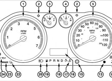
UNDERSTANDING YOUR INSTRUMENT PANEL 197
1 — Headlight Switch 2 — Instrument Cluster 3 — Radio 4 — Upper Switch Bank 5 — Upper Glove Compartment 6 — Lower Glove Compartment
7 — 115v Power Inverter Outlet 8 — Power Outlet 9 — Lower Switch Bank 10 — Cup Holders 11 — Climate Controls 12 — Power Outlet/Cigar Lighter
13 — Transfer Case Position Switch 14 — Ignition Switch 15 — Hood Release 16 — Parking Brake Release
198 UNDERSTANDING YOUR INSTRUMENT PANEL SWITCH BANK BUTTON DESCRIPTION
Upper Switch Bank
The upper switch bank is located on the center of the instrument panel.
1. TOW/HAUL Refer to “Starting And Operating” for more information. 2. ESP OFF Refer to “Starting And Operating” for more information. 3. HAZARD WARNING FLASHER Refer to “What To Do In Emergencies” for more infor- mation. 4. 115V POWER INVERTER Refer to “Understanding The Features Of Your Vehicle” for more information. 5. REAR PARK ASSIST Refer to “Understanding The Features Of Your Vehicle” for more information. 6. TPMS LIGHT LOAD — IF EQUIPPED Refer to “Starting And Operating” for more information.
Lower Switch Bank
The lower switch bank is located on the center of the instrument panel.
UNDERSTANDING YOUR INSTRUMENT PANEL 199
1. HEATED SEATS Refer to “Understanding The Features Of Your Vehicle” for more information. 2. VENTILATED SEATS Refer to “Understanding The Features Of Your Vehicle” for more information. 3. HEATED STEERING WHEEL Refer to “Understanding The Features Of Your Vehicle” for more information.
200 UNDERSTANDING YOUR INSTRUMENT PANEL INSTRUMENT CLUSTER — BASE
INSTRUMENT CLUSTER — PREMIUM
UNDERSTANDING YOUR INSTRUMENT PANEL 201
202 UNDERSTANDING YOUR INSTRUMENT PANEL INSTRUMENT CLUSTER DESCRIPTIONS
1. Tachometer The Tachometer indicates engine speed in revolutions per minute.
CAUTION!
Do not operate the engine with the tachometer pointer at high RPM for extended periods. Engine damage may occur.
2. Turn Signal Indicators
The arrow will flash with the exterior turn signal when the turn signal lever is operated.
NOTE: • A continuous chime will sound if the vehicle is driven more than 1 mile (1.6 km) with either turn signal on.
• Check for an inoperative outside light bulb if either indicator remains on and does not flash, or flashes at a rapid rate. 3. Fuel Gauge Shows level of fuel in tank when ignition switch is in the ON position. 4. Temperature Gauge The temperature gauge shows engine coolant tempera- ture. Any reading within the normal range indicates that the engine cooling system is operating satisfactorily. The gauge pointer will likely indicate a higher tempera- ture when driving in hot weather, up mountain grades, or when towing a trailer. It should not be allowed to exceed the upper limits of the normal operating range.
CAUTION!
Driving with a hot engine cooling system could damage your vehicle. If temperature gauge reads “H” pull over and stop the vehicle. Idle the vehicle with the air conditioner turned off until the pointer drops back into the normal range. If the pointer remains on the “H” and you hear continuous chimes, turn the engine off imme- diately, and call an authorized dealership for service.
WARNING!
A hot engine cooling system is dangerous. You or others could be badly burned by steam or boiling coolant. You may want to call an authorized dealership for service if your vehicle overheats. If you decide to look under the hood yourself, see “Maintaining Your Vehicle”. Follow the warnings under the Cooling Sys- tem Pressure Cap paragraph.
UNDERSTANDING YOUR INSTRUMENT PANEL 203
5. Speedometer The speedometer shows the vehicle speed in miles per hour and/or kilometers per hour (mph/km/h). 6. 4 LOW
This light alerts the driver that the vehicle is in the four-wheel drive LOW mode. The front and rear driveshafts are mechanically locked to- gether forcing the front and rear wheels to rotate at the same speed. Low range provides a greater gear reduction ratio to provide increased torque at the wheels. For further information on four-wheel drive operation and proper use, refer to “Four-Wheel Drive Operation — If Equipped” in “Starting And Operating”.
204 UNDERSTANDING YOUR INSTRUMENT PANEL 7. Electronic Throttle Control (ETC) Light
This light informs you of a problem with the Electronic Throttle Control (ETC) system. The light will come on when the ignition is first turned ON and remain on briefly as a bulb check. If the light does not come on during starting, have the system checked by an authorized dealer. If a problem is detected, the light will come on while the engine is running. Cycle the ignition key when the vehicle has completely stopped and the shift lever is placed in the PARK position, the light should turn off. If the light remains lit with the engine running, your vehicle will usually be drivable; however, see an autho- rized dealer for service as soon as possible. If the light is flashing when the engine is running, immediate service is required and you may experience reduced performance, an elevated/rough idle or engine stall and your vehicle may require towing.
For vehicles equipped with a premium cluster this indi- cator will display in the Electronic Vehicle Information Center (EVIC). Refer to ”Electronic Vehicle Information Center (EVIC) — If Equipped” for further information. 8. 4WD Indicator
This light indicates the vehicle is in four-wheel drive and 4LOCK. 4WD allows all four wheels to receive torque from the engine simulta- neously.
9. 4WD Auto Indicator
The 4WD auto indicator will be illuminated whenever the four-wheel drive mode is auto- matically engaged.
10. SERV (Service) 4WD
The SERV 4WD light monitors the electric shift four-wheel drive system. If the SERV 4WD light stays on or comes on during driving, it means that the four-wheel drive system is not
functioning properly and that service is required. For vehicles equipped with a premium cluster this indi- cator will display in the Electronic Vehicle Information Center (EVIC). Refer to ”Electronic Vehicle Information Center (EVIC) — If Equipped” for further information. 11. TOW/HAUL
The TOW HAUL button is located on the center stack upper switch bank. This light will illuminate when TOW HAUL mode is selected.
UNDERSTANDING YOUR INSTRUMENT PANEL 205
12. Electronic Stability Program (ESP) Indicator Light If this indicator light flashes during accelera- tion, apply as little throttle as possible. While driving, ease up on the accelerator. Adapt your speed and driving to the prevailing road con- ditions, and do not switch off the Electronic Stability Program (ESP) or Traction Control System (TCS). 13. Vehicle Security Light — If EquippedThis light will flash at a fast rate for approxi- mately 15 seconds, when the vehicle security alarm is arming, and then will flash slowly until the vehicle is disarmed.
14. Oil Pressure Gauge The pointer should always indicate some oil pressure when the engine is running. A continuous high or low reading under normal driving conditions may indicate a lubrication system malfunction. service Immediate should be obtained from an authorized dealer.
206 UNDERSTANDING YOUR INSTRUMENT PANEL If the gauge pointer moves to either extreme of NOTE: the gauge, the Check Gauges indicator will illuminate and a single chime will sound. 15. Odometer/Trip Odometer Button/ECO (Fuel Saver Indicator) Button Press this button to toggle between the odometer display, trip odometer display or the “ECO” display. Holding the button in resets the trip odometer reading when in trip mode. 16. Odometer Display / Electronic Vehicle Information Center (EVIC) Display Area — If Equipped
Odometer Display The odometer shows the total distance the vehicle has been driven. U.S. Federal regulations require that upon transfer of vehicle ownership, the seller certify to the purchaser the correct mileage that the vehicle has been driven. If your odometer needs to be repaired or serviced, the repair technician should leave the odometer reading
the same as it was before the repair or service. If s/he cannot do so, then the odometer must be set at zero, and a sticker must be placed in the door jamb stating what the mileage was before the repair or service. It is a good idea for you to make a record of the odometer reading before the repair/service, so that you can be sure that it is properly reset, or that the door jamb sticker is accurate if the odometer must be reset at zero. The two trip odometers show individual trip mileage. To switch from odometer to trip odometers, press and release the TRIP ODOMETER button. To reset a trip odometer, display the desired trip odom- eter to be reset then push and hold the button for approximately two seconds until the display resets.
Vehicle Odometer Messages When the appropriate conditions exist, the following messages will display in the odometer:
ECO . . . . . . . . . . . . . . . . . . . Fuel Saver Indicator Off ECO-ON . . . . . . . . . . . . . . . . Fuel Saver Indicator On door . . . . . . . . . . . . . . . . . . . . . . . . . . . . . Door Ajar Lo tirE . . . . . . . . . . . . . . . . . . . . . . Low Tire Pressure noFUSE . . . . . . . . . . . . . . . . . . . . . . . . . . Fuse Fault CHAngE OIL . . . . . . . . . . . . . . . Oil Change Required LoWASH . . . . . . . . . . . . . . . . . . . . Low Washer Fluid NOTE: There is also an engine hour function. This indicates the total number of hours the engine has been running. To display the engine hours on the base cluster, perform the following: Place the ignition in RUN, but do not start the engine. With the odometer value displayed, hold the TRIP button down for a period of six seconds. The odometer will change to trip value first, then it will
UNDERSTANDING YOUR INSTRUMENT PANEL 207
display the engine hour value. The engine hours will be displayed for a period of 30 seconds until the ignition is turned OFF or the engine is started. Some of the above warnings will be displayed in the Electronic Vehicle Information Center (EVIC) Display Area located in the instrument cluster. Refer to ”Elec- tronic Vehicle Information Center (EVIC) — If Equipped” for further information. ECO / ECO-ON (Fuel Saver Indicator) — If Equipped The ECO-ON indicator will illuminate when you are driving in a fuel efficient manner and can be used to modify driving habits in order to increase fuel economy. The ECO display will toggle between ECO and ECO-ON depending on driving habits and vehicle usage. Press the Odometer / Trip Odometer / ECO (Fuel Saver Indicator) button to change the display from odometer to either of the two trip odometer settings or the “ECO” display.208 UNDERSTANDING YOUR INSTRUMENT PANEL
If the vehicle diagnostic system determines that the fuel filler cap is loose, improperly installed, or damaged, a loose gascap indicator will display in the odometer display area. Tighten the fuel filler cap properly and press the TRIP button to turn off the message. If the problem continues, the message will appear
Loose Gascap Indicator
the next time the vehicle is started. A loose, improperly installed, or damaged fuel filler cap may also turn on the Malfunction Indicator Light (MIL). Lo tirE When the appropriate condition exists, the odometer display will toggle between Lo and tirE for three cycles. noFUSE If the vehicle diagnostic system determines that the Ignition Off Draw (IOD) fuse is improperly installed, or
damaged, a “noFUSE” message will display in the odom- eter display area. For further information on fuses and fuse locations refer to “Fuses” in “Maintaining Your Vehicle”. CHAngE OIL Your vehicle is equipped with an engine oil change indicator system. The CHAngE OIL message will flash in the instrument cluster odometer for approximately 12 seconds after a single chime has sounded to indicate the next scheduled oil change interval. The engine oil change indicator system is duty cycle-based, which means the engine oil change interval may fluctuate dependent upon your personal driving style. Unless reset, this message will continue to display each time you turn the ignition switch to the ON position. To turn off the message temporarily, press and release the Trip Odometer button on the instrument cluster. To reset
the oil change indicator system (after performing the scheduled maintenance), refer to the following proce- dure:
1. Turn the ignition switch to the ON position (Do not start the engine). 2. Fully depress the accelerator pedal slowly three times within 10 seconds. 3. Turn the ignition switch to the OFF/LOCK position. If the indicator message illuminates when you NOTE: start the vehicle, the oil change indicator system did not reset. If necessary repeat this procedure. 17. Engine Temperature Warning Light
This light warns of an overheated engine condi- tion. As temperatures rise and the gauge ap- proaches H, this indicator will illuminate and a single chime will sound after reaching a set threshold. Further overheating will cause the temperature gauge to
UNDERSTANDING YOUR INSTRUMENT PANEL 209
pass H, the indicator will continuously flash and a continuous chime will occur until the engine is allowed to cool. If the light turns on while driving, safely pull over and stop the vehicle. If the A/C system is on, turn it off. Also, shift the transmission into NEUTRAL and idle the ve- hicle. If the temperature reading does not return to normal, turn the engine off immediately and call for service. Refer to “If Your Engine Overheats” in “What To Do In Emergencies” for further information. For vehicles equipped with a premium cluster this indi- cator will display in the Electronic Vehicle Information Center (EVIC). Refer to ”Electronic Vehicle Information Center (EVIC) — If Equipped” for further information. 18. Shift Lever Indicator The Shift Lever Indicator is self-contained within the instrument cluster. It displays the gear position of the automatic transmission.210 UNDERSTANDING YOUR INSTRUMENT PANEL In vehicles with 4.7L or 5.7L engines, the highest NOTE: available transmission gear is displayed in the lower right corner of the Electronic Vehicle Information Center (EVIC) whenever the Electronic Range Select (ERS) fea- ture is active. Use the +/- selector on the shift lever to activate ERS. Refer to “Automatic Transmission” in “Starting And Operating” for further information. 19. Low Fuel Light
When the fuel level reaches approximately 3.0 gal (11.0 L) this light will turn on, and remain on until fuel is added.
For vehicles equipped with a premium cluster this indi- cator will display in the Electronic Vehicle Information Center (EVIC). Refer to ”Electronic Vehicle Information Center (EVIC) — If Equipped” for further information. 20. High Beam Indicator
This indicator shows that headlights are on high beam. Push the multifunction lever forward to
switch the headlights to high beam, and pull toward yourself (normal position) to return to low beam. 21. Voltmeter When the engine is running, the gauge indicates the electrical system voltage. The pointer should stay within the normal range if the battery is charged. If the pointer moves to either extreme left or right and remains there during normal driving, the electrical system should be serviced. NOTE: • The voltmeter may show a gauge fluctuation at vari- ous engine temperatures. This cycling operation is caused by the post-heat cycle of the intake manifold heater system. The number of cycles and the length of the cycling operation is controlled by the engine control module. Post-heat operation can run for sev- eral minutes, and then the electrical system and volt- meter needle will stabilize.
22. Cargo Light
The cargo light will illuminate when the cargo light is activated by pressing the cargo light button on the headlight switch.
23. Brake Warning Light
This light monitors various brake functions, including brake fluid level and parking brake application. If the brake light turns on, it may indicate that the parking brake is applied, that the brake fluid level is low, or that there is a problem with the Anti-lock Brake System reservoir. If the light remains on when the parking brake has been disengaged, and the fluid level is at the full mark on the master cylinder reservoir, it indicates a possible brake hydraulic system malfunction or that a problem with the Brake Booster has been detected by the Anti-Lock Brake System (ABS) / Electronic Stability Program (ESP) sys- tem. In this case, the light will remain on until the
UNDERSTANDING YOUR INSTRUMENT PANEL 211
condition has been corrected. If the problem is related to the brake booster, the ABS pump will run when applying the brake and a brake pedal pulsation may be felt during each stop. The dual brake system provides a reserve braking capac- ity in the event of a failure to a portion of the hydraulic system. A leak in either half of the dual brake system is indicated by the Brake Warning Light, which will turn on when the brake fluid level in the master cylinder has dropped below a specified level. The light will remain on until the cause is corrected. NOTE: The light may flash momentarily during sharp cornering maneuvers, which change fluid level condi- tions. The vehicle should have service performed, and the brake fluid level checked. If brake failure is indicated, immediate repair is neces- sary.212 UNDERSTANDING YOUR INSTRUMENT PANEL
WARNING!
Driving a vehicle with the red brake light on is dangerous. Part of the brake system may have failed. It will take longer to stop the vehicle. You could have an accident. Have the vehicle checked immediately.
Vehicles equipped with the ABS, are also equipped with Electronic Brake Force Distribution (EBD). In the event of an EBD failure, the Brake Warning Light will turn on along with the ABS Light. Immediate repair to the ABS system is required. Operation of the Brake Warning Light can be checked by turning the ignition switch from the OFF position to the ON position. The light should illuminate for approxi- mately two seconds. The light should then turn off unless the parking brake is applied or a brake fault is detected. If the light does not illuminate, have the light inspected by an authorized dealer.
The light also will turn on when the parking brake is applied with the ignition switch in the ON position. NOTE: This light shows only that the parking brake is applied. It does not show the degree of brake application. 24. Oil Pressure Warning Light
This light indicates low engine oil pressure. The light should turn on momentarily when the engine is started. If the light turns on while driving, stop the vehicle and shut off the engine as soon as possible. A chime will sound for four minutes when this light turns on. Do not operate the vehicle until the cause is corrected. This light does not indicate how much oil is in the engine. The engine oil level must be checked under the hood. For vehicles equipped with a premium cluster this indi- cator will display in the Electronic Vehicle Information
Center (EVIC). Refer to ”Electronic Vehicle Information Center (EVIC) — If Equipped” for further information. 25. Tire Pressure Monitoring Telltale Light
Each tire, including the spare (if provided), should be checked monthly, when cold and inflated to the inflation pressure recommended by the vehicle manufacturer on the vehicle placard or tire inflation pressure label. (If your vehicle has tires of a different size than the size indicated on the vehicle placard or tire inflation pressure label, you should determine the proper tire inflation pressure for those tires.) As an added safety feature, your vehicle has been equipped with a Tire Pressure Monitoring System (TPMS) that illuminates a low tire pressure telltale when one or more of your tires is significantly under-inflated. Accordingly, when the low tire pressure telltale illumi- nates, you should stop and check your tires as soon as
UNDERSTANDING YOUR INSTRUMENT PANEL 213
possible, and inflate them to the proper pressure. Driving on a significantly under-inflated tire causes the tire to overheat and can lead to tire failure. Under-inflation also reduces fuel efficiency and tire tread life, and may affect the vehicle’s handling and stopping ability. Please note that the TPMS is not a substitute for proper tire maintenance, and it is the driver’s responsibility to maintain correct tire pressure, even if under-inflation has not reached the level to trigger illumination of the TPMS low tire pressure telltale. Your vehicle has also been equipped with a TPMS malfunction indicator to indicate when the system is not operating properly. The TPMS malfunction indicator is combined with the low tire pressure telltale. When the system detects a malfunction, the telltale will flash for approximately one minute and then remain continuously illuminated. This sequence will continue upon subse- quent vehicle start-ups as long as the malfunction exists.214 UNDERSTANDING YOUR INSTRUMENT PANEL When the malfunction indicator is illuminated, the sys- tem may not be able to detect or signal low tire pressure as intended. TPMS malfunctions may occur for a variety of reasons, including the installation of replacement or alternate tires or wheels on the vehicle that prevent the TPMS from functioning properly. Always check the TPMS malfunction telltale after replacing one or more tires or wheels on your vehicle, to ensure that the replacement or alternate tires and wheels allow the TPMS to continue to function properly.
CAUTION!
The TPMS has been optimized for the original equipment tires and wheels. TPMS pressures and warning have been established for the tire size equipped on your vehicle. Undesirable system opera- tion or sensor damage may result when using re- placement equipment that is not of the same size, type, and/or style. Aftermarket wheels can cause sensor damage. Do not use tire sealant from a can, or balance beads if your vehicle is equipped with a TPMS, as damage to the sensors may result.
NOTE: The TPMS telltale is also accompanied by a “Low Tire” message in the odometer (Base Cluster), or in the Electronic Vehicle Information Center (EVIC) screen indicating “Low Tire” for EVIC enabled clusters.
26. Malfunction Indicator Light (MIL)
The Malfunction Indicator Light (MIL) is part of an onboard diagnostic (OBDII) system which monitors the emissions and engine control sys- tem. If the vehicle is ready for emissions testing, the light will come on when the ignition is first turned on and remain on, as a bulb check, until the engine is started. If the vehicle is not ready for emissions testing the light will come on when the ignition is first turned on and remain on for 15 seconds, then blink for 5 seconds, and remain on until the vehicle is started. If the bulb does not come on during starting, have the condition investigated promptly. If this light comes on and remains on while driving, it suggests a potential engine control problem and the need for system service.
UNDERSTANDING YOUR INSTRUMENT PANEL 215
Although your vehicle will usually be drivable and not need towing, see your authorized dealer for service as soon as possible.CAUTION!
Prolonged driving with the MIL on could cause damage to the engine control system. It also could affect fuel economy and drivability. If the MIL is flashing, severe catalytic converter damage and power loss will soon occur. Immediate service is required.
216 UNDERSTANDING YOUR INSTRUMENT PANEL
WARNING!
A malfunctioning catalytic converter, as referenced above, can reach higher temperatures than in normal operating conditions. This can cause a fire if you drive slowly or park over flammable substances such as dry plants or wood or cardboard, etc. This could result in death or serious injury to the driver, occu- pants or others.
27. Airbag Warning Light
This light turns on and remains on for six to eight seconds as a bulb check when the ignition switch is first turned ON. If the light is not on during starting, stays on, or turns on while driving, have the system inspected by an authorized dealer as soon as possible. Refer to “Occupant Restraints” in “Things To Know Before Starting Your Vehicle” for further information.
28. Front Fog Light Indicator — If Equipped
This indicator will illuminate when the front fog lights are on.
29. Anti-Lock Brake (ABS) Light
This light monitors the Anti-lock Brake System (ABS). The light will turn on when the ignition switch is turned to the ON position and may stay on for as long as four seconds.
If the ABS light remains on or turns on while driving, it indicates that the anti-lock portion of the brake system is not functioning and that service is required. However, the conventional brake system will continue to operate normally if the BRAKE warning light is not on. If the ABS light is on, the brake system should be serviced as soon as possible to restore the benefits of anti-lock brakes. If the ABS light does not turn on when the ignition switch is turned to the ON position, have the light inspected by an authorized dealer.
30. Transmission Temperature Warning Light
This light indicates that there is excessive trans- mission fluid temperature that might occur with severe usage such as trailer towing. It may also occur when operating the vehicle in a high torque converter slip condition, such as 4-wheel-drive operation (e.g., snow plowing, off- road operation). If this light comes on, stop the vehicle and run the engine at idle or faster, with the transmission in NEUTRAL until the light goes off.
CAUTION!
Continuous driving with the Transmission Tempera- ture Warning Light illuminated will eventually cause severe transmission damage or transmission failure.
UNDERSTANDING YOUR INSTRUMENT PANEL 217
WARNING!
In some circumstances a Transmission Temperature Warning Light, under continued operation, could cause the fluid to boil over, come in contact with hot engine or exhaust components and cause a fire.
For vehicles equipped with a premium cluster this warn- ing light will display in the Electronic Vehicle Informa- tion Center (EVIC). Refer to ”Electronic Vehicle Informa- tion Center further information. 31. Seat Belt Reminder Light
(EVIC) — If Equipped” for
When the ignition switch is first turned ON, this light will turn on for five to eight seconds as a bulb check. During the bulb check, if the driver’s seat belt is unbuckled, a chime will sound. After the bulb check or when driving, if the driver’s seat belt remains unbuckled, the seat belt reminder light will flash or
218 UNDERSTANDING YOUR INSTRUMENT PANEL remain on continuously. Refer to “Occupant Restraints” in “Things To Know Before Starting Your Vehicle” for further information. 32. Charging System Light
This light shows the status of the electrical charg- ing system. The light should come on when the ignition switch is first turned ON and remain on briefly as a bulb check. If the light stays on or comes on while driving, turn off some of the vehicle’s non-essential electrical devices or increase engine speed (if at idle). If the charging system light remains on, it means that the vehicle is experiencing a problem with the charging system. Obtain SERVICE IMMEDIATELY. See an autho- rized dealer. If jump starting is required, refer to “Jump Starting Procedures” in “What To Do In Emergencies”. For vehicles equipped with a premium cluster this indi- cator will display in the Electronic Vehicle Information
Center (EVIC). Refer to ”Electronic Vehicle Information Center (EVIC) — If Equipped” for further information. 33. Electronic Stability Program (ESP) Indicator Light / Brake Assist System (BAS) Warning Light
The malfunction light for the Electronic Stabil- ity Program (ESP) is combined with Brake Assist System (BAS). The yellow “ESP/BAS Warning Light” comes on when the ignition switch is turned to the “ON” position. They should go out with the engine running. If the “ESP/BAS Warning Light” comes on continuously with the engine running, a malfunction has been detected in either the ESP or the BAS system. If this light remains on after several ignition cycles, and the vehicle has been driven several miles (kilometers) at speeds greater than 30 mph (48 km/h), see an authorized dealer as soon as possible. For vehicles equipped with a premium cluster this indi- cator will display in the Electronic Vehicle Information
Center (EVIC). Refer to ”Electronic Vehicle Information Center (EVIC) — If Equipped” for further information.
WARNING!
If a warning light remains on the system may not be working and you will not have the benefit of ESP or BAS. Under certain driving conditions, where ESP or BAS would be beneficial, you - if you have not adjusted your driving speeds and stopping in or to account for the lack of the feature, may be in acci- dent.
ELECTRONIC VEHICLE INFORMATION CENTER (EVIC) — IF EQUIPPED The Electronic Vehicle Information Center (EVIC) fea- tures a driver-interactive display that is located in the instrument cluster.
UNDERSTANDING YOUR INSTRUMENT PANEL 219
Electronic Vehicle Information Center (EVIC)
NOTE: The compass on your vehicle is self-calibrating, eliminating the need to manually calibrate the compass.
220 UNDERSTANDING YOUR INSTRUMENT PANEL This system conveniently allows the driver to select a variety of useful information by pressing the switches mounted on the steering wheel. The EVIC consists of the following: • System Status display • Vehicle information warning message displays • Customer-Programmable Features (SETUP) • Compass display • Outside temperature display • Trip computer functions • Distance To Empty (DTE) display • Average Fuel Economy / Fuel Saver Mode display • Audio Modes display
Steering wheel EVIC control button, as it appears on the left side of the steer- ing wheel.
Press and release the UP button to scroll up- ward through the main menus (DTE, mi/gal, System Info, Messages, Units, Setup) and sub menus. Press and release the DOWN button to scroll downward through the main menus and sub menus.
Steering wheel EVIC control button as it appears on the right side of the steering wheel.
Press and release the SELECT button for access to main menus, sub menus or to select a personal setting in the system setup menu.
Press the BACK button to scroll back to a previous menu or sub menu.
EVIC Displays When the appropriate conditions exist, the EVIC displays the following messages: • ECO (Fuel Saver Indicator) — If Equipped
motion)
UNDERSTANDING YOUR INSTRUMENT PANEL 221
• Door(s) Ajar (with a single chime, if vehicle is in • Wrong Key • Damaged Key • Key not programmed • Key In Ignition • Turn Signal On • RKE Battery Low • LOW WASHER FLUID • Oil Change Due > Dealer Info • Park Assist On • Warning Object Detected • Park Assist Disabled
222 UNDERSTANDING YOUR INSTRUMENT PANEL
• Left Front Turn Signal Light Out • Left Rear Turn Signal Light Out • Right Front Turn Signal Light Out • Right Rear Turn Signal Light Out • Park Assist Disabled • Service Park Assist System • Personal Settings Not Available — Vehicle Not in Park • Remote start aborted — Door ajar • Remote start aborted — Hood ajar • Remote start aborted — Fuel low • Remote start disabled — System fault • Remote start disabled — Turn key • Remote start active — Key to Run
EVIC Warning Lights • Door Ajar
This light will turn on to indicate that one or more door may be ajar.
• Oil Pressure Warning Light
This light indicates low engine oil pressure. The light should turn on momentarily when the engine is started. If the light turns on while driving, stop the vehicle and shut off the engine as soon as possible. A chime will sound for four minutes when this light turns on. Do not operate the vehicle until the cause is corrected. This light does not show how much oil is in the engine. The engine oil level must be checked under the hood.
• Charging System Light
This light shows the status of the electrical charg- ing system. The light should come on when the ignition switch is first turned ON and remain on briefly as a bulb check. If the light stays on or comes on while driving, turn off some of the vehicle’s non-essential electrical devices or increase engine speed (if at idle). If the charging system light remains on, it means that the vehicle is experiencing a problem with the charging system. Obtain SERVICE IMMEDIATELY. See an autho- rized dealer. If jump starting is required, refer to “Jump Starting Procedures” in “What To Do In Emergencies”. • Electronic Speed Control Light
This light will turn on when the electronic speed control is ON.
UNDERSTANDING YOUR INSTRUMENT PANEL 223
• Electronic Throttle Control (ETC) Light
This light informs you of a problem with the Electronic Throttle Control (ETC) system. The light will come on when the ignition is first turned ON and remain on briefly as a bulb check. If the light does not come on during starting, have the system checked by an authorized dealer. If a problem is detected, the light will come on while the engine is running. Cycle the ignition key when the vehicle has completely stopped and the shift lever is placed in the PARK position. The light should turn off. If the light remains lit with the engine running your vehicle, will usually be drivable, however, see an autho- rized dealer for service as soon as possible. If the light is flashing when the engine is running, immediate service is required and you may experience reduced performance, an elevated/rough idle or engine stall and your vehicle may require towing.
224 UNDERSTANDING YOUR INSTRUMENT PANEL
• Engine Temperature Warning Light
This light warns of an overheated engine condi- tion. As temperatures rise and the gauge ap- proaches H, this indicator will illuminate and a single chime will sound after reaching a set threshold. Further overheating will cause the temperature gauge to pass H, the indicator will continuously flash and a continuous chime will occur until the engine is allowed to cool. If the light turns on while driving, safely pull over and stop the vehicle. If the A/C system is on, turn it off. Also, shift the transmission into NEUTRAL and idle the ve- hicle. If the temperature reading does not return to normal, turn the engine off immediately and call for service. Refer to “If Your Engine Overheats” in “What To Do In Emergencies” for more information.
• SERV 4WD
The SERV 4WD light monitors the electric shift 4WD system. If the SERV 4WD light stays on or comes on during driving, it means that the 4WD system is not functioning properly and that service is required. • Electronic Stability Program (ESP) Indicator Light /
Brake Assist System (BAS) Warning Light
The malfunction light for the Electronic Stabil- ity Program (ESP) is combined with Brake Assist System (BAS). The yellow ESP/BAS Warning Light comes on when the ignition switch is turned to the ON position. They should go out with the engine running. If the ESP/BAS Warning Light comes on continuously with the engine running, a mal- function has been detected in either the ESP or the BAS system. If this light remains on after several ignition
cycles and the vehicle has been driven several miles at speeds greater than 30 mph (48 km/h), see an authorized dealer as soon as possible. • Transmission Temperature Light
This light indicates that there is excessive trans- mission fluid temperature that might occur with severe usage such as trailer towing. It may also occur when operating the vehicle in a high torque converter slip condition, such as 4-wheel-drive operation (e.g., snow plowing, off- road operation). If this light comes on, stop the vehicle and run the engine at idle or faster, with the transmission in NEUTRAL until the light goes off.
CAUTION!
Continuous driving with the Transmission Tempera- ture Indicator illuminated will eventually cause se- vere transmission damage or transmission failure.
UNDERSTANDING YOUR INSTRUMENT PANEL 225
WARNING!
In some circumstances a Transmission Temperature Indicator, under continued operation, could cause the fluid to boil over, come in contact with hot engine or exhaust components and cause a fire. • Loose Gascap Indicator
If the vehicle diagnostic system determines that the fuel filler cap is loose, improperly installed, or damaged, a loose gascap indicator will display in the telltale display area. Tighten the fuel filler cap properly and press the SELECT button to turn off the message. If the problem continues, the message will appear the next time the vehicle is started. A loose, improperly installed, or damaged fuel filler cap may also turn on the Malfunction Indicator Light (MIL).
226 UNDERSTANDING YOUR INSTRUMENT PANEL Oil Change Due Your vehicle is equipped with an engine oil change indicator system. The Oil Change Due message will flash in the EVIC display for approximately 10 seconds after a single chime has sounded to indicate the next scheduled oil change interval. The engine oil change indicator system is duty-cycle based, which means the engine oil change interval may fluctuate dependent upon your personal driving style. Unless reset, this message will continue to display each time you turn the ignition switch to the ON position. To turn off the message temporarily, press and release the RETURN button. To reset the oil change indicator system (after performing the scheduled maintenance) perform the following steps. 1. Turn the ignition switch to the ON position. (Do not start the engine)
2. Fully depress the accelerator pedal slowly three times within 10 seconds. 3. Turn the ignition switch to the OFF position. If the indicator message illuminates when you NOTE: start the engine, the oil change indicator system did not reset. If necessary, repeat these steps. Distance To Empty (DTE)
Shows the estimated distance that can be traveled with the fuel remaining in the tank. This estimated distance is determined by a weighted average of the instantaneous and average fuel economy, according to the current fuel tank level. DTE cannot be reset through the RETURN button. NOTE: Significant changes in driving style or vehicle loading will greatly affect the actual drivable distance of the vehicle, regardless of the DTE displayed value.
When the DTE value is less than 30 miles (48 km) estimated driving distance, the DTE display will change to a text display of ⬙LOW FUEL.⬙ This display will continue until the vehicle runs out of fuel. Adding a significant amount of fuel to the vehicle will turn off the ⬙LOW FUEL⬙ text and a new DTE value will display. Average Fuel Economy / Fuel Saver Mode — If Equipped
Shows the average fuel economy since the last reset. When the fuel economy is reset, the display will read “RESET” or show dashes for two seconds. Then, the history information will be erased, and the averaging will continue from the last fuel average reading before the reset. The FUEL SAVER MODE message will display above the average fuel economy in the EVIC display. This message
UNDERSTANDING YOUR INSTRUMENT PANEL 227
will appear whenever MDS (if equipped) allows the engine to operate on four cylinders, or if you are driving in a fuel efficient manner.Fuel Saver Mode — On
This feature allows you to monitor when you are driving in a fuel efficient manner, and it can be used to modify driving habits in order to increase fuel economy.
228 UNDERSTANDING YOUR INSTRUMENT PANEL Trip Functions Press and release the ODOMETER/TRIP ODOMETER button until one of the following Trip Functions displays in the EVIC: • Trip A • Trip B • Elapsed Time Press the ODOMETER/TRIP ODOMETER button to cycle through all the Trip Computer functions. The Trip Functions mode displays the following informa- tion. • Trip A Shows the total distance traveled for Trip A since the last reset.
• Trip B Shows the total distance traveled for Trip B since the last reset. • Elapsed Time Shows the total elapsed time of travel since the last reset when the ignition switch is in the ACC position. Elapsed time will increment when the ignition switch is in the ON or START position. To Reset The Display Reset will only occur while a resettable function is being displayed. Press and release the ODOMETER/TRIP ODOMETER button once to clear the resettable function being displayed. To reset all resettable functions, press and release the ODOMETER/TRIP ODOMETER button a second time within three seconds of resetting the currently-displayed function. (Reset ALL will display during this three-second window).
System (Customer Information Features) Press and release the UP or DOWN button until “SYS- TEM” displays in the EVIC and press the SELECT button. Press the UP and DOWN button to scroll through the available information displays, then press SELECT to display anyone of the following choices. • Coolant Temp Displays the actual coolant temperature. • Oil Temperature Displays the actual oil temperature. • Oil Pressure Displays the actual oil pressure. • Trans Temperature Displays the actual transmission temperature. • Engine Hours Displays the hours of engine operation.
UNDERSTANDING YOUR INSTRUMENT PANEL 229
Compass / Temperature Display
The compass readings indicate the direction the vehicle is facing. Press and release the compass button to display one of eight compass readings and the outside tempera- ture.
COMPASS
Button
NOTE: • The system will display the last known outside tem- perature when starting the vehicle and may need to be driven several minutes before the updated tempera- ture is displayed. Engine temperature can also affect the displayed temperature, therefore temperature readings are not updated when the vehicle is not moving. • During snowplow usage on vehicles equipped with outside temperature display, the display may show higher temperatures than the outside ambient tem- perature. The higher displayed temperature is due to
230 UNDERSTANDING YOUR INSTRUMENT PANEL
blocked or reduced airflow to the underhood ambient temperature sensor caused by the snowplow. In addi- tion, on vehicles equipped with Automatic Tempera- ture Control (ATC), it is suggested that the interior cabin temperature be manually controlled should the system not perform as desired while in automatic mode. Both the outside temperature display and ATC operation will return to normal when the snowplow is removed.
Automatic Compass Calibration This compass is self-calibrating, which eliminates the need to manually reset the compass. When the vehicle is new, the compass may appear erratic and the EVIC will display CAL until the compass is calibrated. You may also calibrate the compass by completing one or more 360–degree turns (in an area free from large metal or metallic objects) until the CAL indicator displayed in the EVIC turns off. The compass will now function normally.
NOTE: A good calibration requires a level surface and an environment free from large metallic objects such as buildings, bridges, underground cables, railroad tracks, etc. Manual Compass Calibration If the compass appears erratic and the CAL indicator does not appear in the EVIC display, you must put the compass into the Calibration Mode manually, as follows: 1. Turn ON the ignition switch. 2. Press the UP or DOWN button until the Setup (Customer-Programmable Features) menu is reached, then press the SELECT button. 3. Press the DOWN button until “Calibrate Compass” is displayed in the EVIC. 4. Press and release the SELECT button to start the calibration. The “CAL” indicator will be displayed in the EVIC.
5. Complete one or more 360–degree turns (in an area free from large metal or metallic objects) until the “CAL” indicator turns off. The compass will now function normally. Compass Variance Compass Variance is the difference between Magnetic North and Geographic North. To compensate for the differences the variance should be set for the zone where the vehicle is driven, per the zone map. Once properly set, the compass will automatically compensate for the differences, and provide the most accurate compass heading. For the most accurate compass performance, the compass must be set using the following steps. NOTE: Keep magnetic materials away from the top of the instrument panel, such as iPod’s, Cell Phones, Lap- tops and Radar Detectors. This is where the compass module is located, and it can cause interference with the compass sensor, and it may give false readings.
UNDERSTANDING YOUR INSTRUMENT PANEL 231
Compass Variance Map
1. Turn the ignition switch ON. 2. Press the UP or DOWN button until the Setup (Customer-Programmable Features) menu is reached, then press the SELECT button.
232 UNDERSTANDING YOUR INSTRUMENT PANEL 3. Press the DOWN button until the “Compass Variance” message is displayed in the EVIC, then press the SELECT button. The last variance zone number displays in the EVIC. 4. Press and release the SELECT button until the proper variance zone is selected, according to the map. 5. Press and release the RETURN button to exit. Customer-Programmable Features (System Setup) Personal Settings allows you to set and recall features when the transmission is in PARK. If the transmission is out of PARK or the vehicle begins moving, a warning message SYSTEM SETUP NOT AVAILABLE, is fol- lowed in three seconds by, VEHICLE NOT IN PARK. Press and release the UP or DOWN button until Setup displays in the EVIC.
Use the UP or DOWN button to display one of the following choices. Select Language When in this display you may select one of five lan- guages for all display nomenclature, including the trip functions and the navigation system (if equipped). Press the UP or DOWN button while in this display and scroll through the language choices. Press the SELECT button to select English, Spanish (Español), French (Français), Italian (Italiano), German (Deutsch), and Dutch (Neder- lands). Then, as you continue, the information will dis- play in the selected language. Nav–Turn By Turn When this feature is selected, the navigation system utilizes voice commands, guiding through the drive route, mile by mile, turn-by-turn until the final destina- tion is reached. To make your selection, press and release the SELECT button until a check-mark appears next to
the feature showing the system has been activated or the check-mark is removed, showing the system has been deactivated. Enable/Disable the Rear Park Assist System The Rear Park Assist system will scan for objects behind the vehicle when the transmission is in the REVERSE and the vehicle speed is less than 11 mph (18 km/h). The system can be enabled with Sound Only, Sound and Display, or turned OFF through the EVIC. To make your selection, press and release the SELECT button until a check-mark appears next to the feature showing the system has been activated or the check-mark is removed, showing the system has been deactivated. Refer to “Rear Park Assist System” in “Understanding The Features Of Your Vehicle” for system function and operating information.
UNDERSTANDING YOUR INSTRUMENT PANEL 233
Auto Lock Doors When this feature is selected, all doors will lock auto- matically when the vehicle reaches a speed of 15 mph (24 km/h). To make your selection, press and release the SELECT button until a check-mark appears next to the feature showing the system has been activated, or the check-mark is removed showing the system has been deactivated. Auto Unlock Doors When this feature is selected, all doors will unlock when the vehicle is stopped and the transmission is in the PARK or NEUTRAL position and the driver’s door is opened. To make your selection, press and release the SELECT button until a check-mark appears next to the feature showing the system has been activated, or the check-mark is removed showing the system has been deactivated.
234 UNDERSTANDING YOUR INSTRUMENT PANEL 1st Press RKE When Driver Door 1st Press is selected, only the driver’s door will unlock on the first press of the RKE transmitter UNLOCK button. When Driver Door 1st Press is selected, you must press the RKE transmitter UNLOCK button twice to unlock the passenger’s doors. When All Doors 1st Press is selected, all of the doors will unlock on the first press of the RKE transmitter UNLOCK button. To make your selection, press and release the SELECT button until “Driver Door 1st Press” or “All Doors 1st Press” appears. RKE Linked To Memory When this feature is selected the memory seat, mirror, and radio settings will return to the memory set position when the RKE transmitter UNLOCK button is pressed. If this feature is not selected then the memory seat, mirror, and radio settings can only return to the memory set position using the seat mounted switch. To make your selection, press and release the SELECT button until a
check-mark appears next to the feature showing the system has been activated or the check-mark is removed, showing the system has been deactivated. Remote Start Comfort Sys. When this feature is selected and the remote start is activated, the heated steering wheel and driver heated seat features will automatically turn on in cold weather. In warm weather, the driver vented seat feature will automatically turn on when the remote start is activated. These features will stay on through the duration of remote start or until the key is turned to RUN. To make your selection, press and release the SELECT button until a check-mark appears next to the feature showing the system has been activated or the check-mark is removed, showing the system has been deactivated. Horn With Remote Start When this feature is selected, a short horn sound will occur when the RKE transmitter REMOTE START button
is pressed. To make your selection, press and release the SELECT button until a check-mark appears next to the feature showing the system has been activated or the check-mark is removed, showing the system has been deactivated. Horn With Remote Lock When this feature is selected, a short horn sound will occur when the RKE transmitter LOCK button is pressed. This feature may be selected with or without the Flash Lamps with Lock feature. To make your selection, press and release the SELECT button until a check-mark ap- pears next to the feature showing the system has been activated or the check-mark is removed, showing the system has been deactivated. Flash Lamps With Lock When this feature is selected, the front and rear turn signals will flash when the doors are locked or unlocked with the RKE transmitter. This feature may be selected
UNDERSTANDING YOUR INSTRUMENT PANEL 235
with or without the sound horn on lock feature selected. To make your selection, press and release the SELECT button until a check-mark appears next to the feature showing the system has been activated or the check-mark is removed, showing the system has been deactivated. Headlamp Off Delay When this feature is selected, the driver can choose to have the headlights remain on for 0, 30, 60, or 90 seconds when exiting the vehicle. To make your selection, press and release the SELECT button until 0, 30, 60, or 90
appears. Headlamps With Wipers When this feature is selected and the HEADLIGHT switch is in the AUTO position, the headlights will turn on approximately 10 seconds after the wipers are turned on. The headlights will also turn off when the wipers are turned off if they were turned on by this feature. To make your selection, press and release the SELECT button until236 UNDERSTANDING YOUR INSTRUMENT PANEL a check-mark appears next to the feature showing the system has been activated or the check-mark is removed, showing the system has been deactivated. Automatic High Beams — If Equipped When this feature is selected, the high beam headlights will deactivate automatically under certain conditions. To make your selection, press and release the SELECT button until a check-mark appears next to the feature showing the system has been activated or the check-mark is removed, showing the system has been deactivated. Refer to “SmartBeam™” in “Understanding The Features Of Your Vehicle”. Wiper Mode — If Equipped When this feature is selected, the system will automati- cally activate the windshield wipers if it senses moisture on the windshield. To make your selection, press and release the SELECT button until a check-mark appears next to the feature showing the system has been activated
or the check-mark is removed, showing the system has been deactivated. When this feature is deactivated, the system reverts to the standard intermittent wiper operation. Easy Exit Seat — If Equipped When this feature is selected it provides automatic driver seat positioning to enhance driver mobility when enter- ing and exiting the vehicle. To make your selection, press and release the SELECT button until a check-mark ap- pears next to the feature showing the system has been activated or the check-mark is removed, showing the system has been deactivated. NOTE: The seat will return to the memorized seat location (if Recall Memory with Remote Key Unlock is set to ON) when the RKE transmitter is used to unlock the door. Refer to “Driver Memory Seat” in “Understanding The Features Of Your Vehicle” for further information.
Tilt Mirror In Reverse When this feature is selected and the shift lever is placed in reverse gear, the side mirrors tilt downward to allow the driver to see into the previous blind spot and avoid objects in close proximity to the rear of the vehicle. To make your selection, press and release the SELECT button until a check-mark appears next to the feature showing the system has been activated or the check-mark is removed, showing the system has been deactivated. Key-Off Power Delay When this feature is selected, the power window switches, radio, hands-free system (if equipped), DVD video system (if equipped), power sunroof (if equipped), and power outlets will remain active for up to 10 minutes after the ignition switch is turned OFF. Opening a vehicle door will cancel this feature. To make your selection, press and release the SELECT button until Off, 45 sec., 5 min., or 10 min. appears.
UNDERSTANDING YOUR INSTRUMENT PANEL 237
Illuminated Approach When this feature is selected, the headlights will activate and remain on for up to 90 seconds when the doors are unlocked with the RKE transmitter. To make your selec- tion, press and release the SELECT button until “OFF,” “30 sec.,” “60 sec.,” or “90 sec.” appears. Hill Start Assist (HSA) When on is selected, the HSA system is active. Refer to “Electronic Brake Control System” in “Starting And Operating” for system function and operating informa- tion. To make your selection, press and release the SELECT button until a check-mark appears next to the feature showing the system has been activated or the check-mark is removed, showing the system has been deactivated.
238 UNDERSTANDING YOUR INSTRUMENT PANEL Display Fuel Saver — If Equipped The “Fuel Saver Mode” message is located in the Compass/Temperature display, this message can be turned on or off. To make your selection, press and release the FUNCTION SELECT button until “ON” or “OFF” appears. Display Units of Measure In and navigation system (if The EVIC, odometer, equipped) can be changed between English and Metric units of measure. To make your selection, press and release the SELECT button until ENGLISH or METRIC appears. Compass Variance Refer to “Compass Display” for more information. Calibrate Compass Refer to “Compass Display” for more information.
MEDIA CENTER 730N/430 (RER/REN/RBZ) — AM/FM STEREO RADIO AND CD/DVD/HDD/NAV — IF EQUIPPED
NOTE: The sales code is located on the lower right side of the unit’s faceplate. The REN, RER and RBZ radios contain a CD/DVD player, USB port, and a 30-gigabyte hard drive (HDD). Sirius Satellite Radio is optional. The 6.5 in (16.5 cm) touch screen allows for easy menu selection. The RER radio also contains a Global Positioning System (GPS)-based Navigation system. Refer to your Uconnect™ Multimedia REN, RER or RBZ user’s manual for detailed operating instructions. Operating Instructions — Voice Command System — If Equipped Refer to “Voice Command” in the Uconnect™ User Manual located on the DVD for further details.
Operating Instructions — Uconnect™ Phone — If Equipped Refer to “Uconnect™ Phone” in the Uconnect™ User Manual located on the DVD for further details. Clock Setting Procedure — RBZ Radio
To Manually Set the Clock 1. Turn on the radio. 2. Touch the screen where the time is displayed, the clock setting menu will appear on the screen. 3. To move the hour forward, touch the screen where the word “Hour” with the arrow pointing upward is dis- played. To move the hour backward, touch the screen where the word “Hour” with the arrow pointing down- ward is displayed. 4. To move the minute forward, touch the screen where the word “Min” with the arrow pointing upward is
UNDERSTANDING YOUR INSTRUMENT PANEL 239
displayed. To move the minute backward, touch the screen where the word “Min” with the arrow pointing downward is displayed. 5. To save the new time setting, touch the screen where the word “Save” is displayed. Changing Daylight Savings Time When selected, this feature will display the time of day in daylight savings time. Proceed as follows to change the current setting: 1. Turn on the radio. 2. Touch the screen where the time is displayed. The clock setting menu will appear on the screen. 3. When this feature is on, a check mark will appear in the box next to the words “Daylight Savings.” Touch the screen where the words “Daylight Savings” are dis- played to change the current setting.240 UNDERSTANDING YOUR INSTRUMENT PANEL Show Time if Radio is Off When selected, this feature will display the time of day on the touch screen when the radio is turned off. Proceed as follows to change the current setting: 1. Turn on the radio. 2. Touch the screen where the time is displayed. The clock setting menu will appear on the screen. 3. When this feature is on, a check mark will appear in the box next to the words “Show Time if Radio is Off.” Touch the screen where the words “Show Time if Radio is Off” are displayed to change the current setting. Changing the Time Zone 1. Turn on the radio. 2. Touch the screen where the time is displayed. The clock setting menu will appear on the screen.
3. Touch the screen where the words “Set Time Zone” are displayed. The time zone selection menu will appear on the screen. 4. Select a time zone by touching the screen where your selection appears. If you do not see a time zone that you want to select, touch the screen where the word “Page” is displayed to view additional time zones in the menu. 5. Touch the screen where the word “Save” is displayed. Clock Setting Procedure — RER/REN Radio Uconnect威 gps — RER Only The GPS receiver used in this system is synchronized to the time data being transmitted by the GPS satellite. The satellite clock is Greenwich Mean Time (GMT). This is the worldwide standard for time. This makes the system’s clock very accurate once the appropriate time zone and daylight savings information is set.
To Manually Set the Clock — RER/REN 1. Turn on the radio. 2. Touch the screen where the time is displayed. 3. Touch the screen where “User Clock” is displayed, the clock setting menu will appear on the screen. 4. To move the hour forward, touch the screen where the word “Hour” with the arrow pointing upward is dis- played. To move the hour backward, touch the screen where the word “Hour” with the arrow pointing down- ward is displayed. 5. To move the minute forward, touch the screen where the word “Min” with the arrow pointing upward is displayed. To move the minute backward, touch the screen where the word “Min” with the arrow pointing downward is displayed.
UNDERSTANDING YOUR INSTRUMENT PANEL 241
6. To save the new time setting, touch the screen where the word “Save” is displayed. Changing Daylight Savings Time When selected, this feature will display the time of day in daylight savings time. Proceed as follows to change the current setting: 1. Turn on the radio. 2. Touch the screen where “User Clock” is displayed, the clock setting menu will appear on the screen. 3. When this feature is on, a check mark will appear in the box next to the words “Daylight Savings.” Touch the screen where the words “Daylight Savings” are dis- played to change the current setting.242 UNDERSTANDING YOUR INSTRUMENT PANEL Show Time if Radio is Off When selected, this feature will display the time of day on the touch screen when the radio is turned off. Proceed as follows to change the current setting: 1. Turn on the radio. 2. Touch the screen where the time is displayed. 3. Touch the screen where “User Clock” is displayed, the clock setting menu will appear on the screen. 4. When this feature is on, a check mark will appear in the box next to the words “Show Time if Radio is Off.” Touch the screen where the words “Show Time if Radio is Off” are displayed to change the current setting.
Changing the Time Zone 1. Turn on the radio. 2. Touch the screen where the time is displayed. 3. Touch the screen where “User Clock” is displayed, the clock setting menu will appear on the screen. 4. Touch the screen where the words “Set Time Zone” are displayed. The time zone selection menu will appear on the screen. 5. Select a time zone by touching the screen where your selection appears. If you do not see a time zone that you want to select, touch the screen where the word “Page” is displayed to view additional time zones in the menu. 6. Touch the screen where the word “Save” is displayed.