- Download PDF Manual
-
creased durability does not necessarily increase the vehi- cle’s GVWR. Tire Size The tire size on the Label represents the actual tire size on your vehicle. Replacement tires must be equal to the load capacity of this tire size.
Rim Size This is the rim size that is appropriate for the tire size listed. Inflation Pressure This is the cold tire inflation pressure for your vehicle for all loading conditions up to full GAWR. Curb Weight The curb weight of a vehicle is defined as the total weight of the vehicle with all fluids, including vehicle fuel, at full capacity conditions, and with no occupants or cargo loaded into the vehicle. The front and rear curb weight values are determined by weighing your vehicle on a commercial scale before any occupants or cargo are added.
Loading The actual total weight and the weight of the front and rear of your vehicle at the ground can best be determined by weighing it when it is loaded and ready for operation. The entire vehicle should first be weighed on a commer- cial scale to insure that the GVWR has not been exceeded. The weight on the front and rear of the vehicle should then be determined separately to be sure that the load is properly distributed over front and rear axle. Weighing the vehicle may show that the GAWR of either the front or rear axles has been exceeded but the total load is within the specified GVWR. If so, weight must be shifted from front to rear or rear to front as appropriate until the specified weight limitations are met. Store the heavier items down low and be sure that the weight is distributed equally. Stow all loose items securely before driving.
STARTING AND OPERATING 383
Improper weight distributions can have an adverse effect on the way your vehicle steers and handles and the way the brakes operate.
CAUTION!
Do not load your vehicle any heavier than the GVWR or the maximum front and rear GAWR. If you do, parts on your vehicle can break, or it can change the way your vehicle handles. This could cause you to lose control. Also overloading can shorten the life of your vehicle.
384 STARTING AND OPERATING
An EXAMPLE of a loaded vehicle is shown in the following chart. Note that neither GVWR nor GAWR capabilities are exceeded. Overloading can cause poten- tial safety hazards and shorten service life.
NOTE: The weights shown in this chart are not necessarily the weights for your vehicle. Also, the amount of load added to both the front and rear axles can be computed after the vehicle has been weighed both in its (curb weight( condition, and in its (loaded and ready for operation( condition.
Gross Vehicle Weight Rating (GVWR) 6500 LBS (2948 kg).
TRAILER TOWING In this section you will find safety tips and information on limits to the type of towing you can reasonably do with your vehicle. Before towing a trailer carefully re- view this information to tow your load as efficiently and safely as possible. To maintain warranty coverage, follow the requirements and recommendations in this manual concerning ve- hicles used for trailer towing. Common Towing Definitions The following trailer towing related definitions will assist you in understanding the following information: Gross Vehicle Weight Rating (GVWR) The GVWR is the total allowable weight of your vehicle. This includes driver, passengers, cargo and tongue weight. The total load must be limited so that you do not exceed the GVWR.
STARTING AND OPERATING 385
Gross Trailer Weight (GTW) The gross trailer weight (GTW) is the weight of the trailer plus the weight of all cargo, consumables and equipment (permanent or temporary) loaded in or on the trailer in its 9loaded and ready for operation9 condition. The recom- mended way to measure GTW is to put your fully loaded trailer on a vehicle scale. The entire weight of the trailer must be supported by the scale. Gross Combination Weight Rating (GCWR) The gross combination weight rating (GCWR) is the total permissible weight of your vehicle and trailer when weighed in combination. (Note that GCWR ratings in- clude a 68 kg (150 lbs) allowance for the presence of a driver).
386 STARTING AND OPERATING
Gross Axle Weight Rating (GAWR) The GAWR is the maximum capacity of the front and rear axles. Distribute the load over the front and rear axles evenly. Make sure that you do not exceed either front or rear GAWR.
WARNING!
It is important that you do not exceed the maximum front or rear GAWR. A dangerous driving condition can result if either rating is exceeded. You could lose control of the vehicle and have an accident.
Tongue Weight (TW) The downward force exerted on the hitch ball by the trailer. In most cases it should not be less than 10% or more than 15% of the trailer load. You must consider this as part of the load on your vehicle. Frontal Area The maximum height and maximum width of the front of a trailer. Trailer Sway Control The trailer sway control is a telescoping link that can be installed between the hitch receiver and the trailer tongue that typically provides adjustable friction associated with the telescoping motion to dampen any unwanted trailer swaying motions while traveling.
Weight-Carrying Hitch A weight-carrying hitch supports the trailer tongue weight, just as if it were luggage located at a hitch ball or some other connecting point of the truck. These kind of hitches are the most popular on the market today and they’re commonly used to tow small- and medium-sized trailers. Weight-Distributing Hitch A weight-distributing system works by applying lever- age through spring (load) bars. They are typically used for heavier loads, to distribute trailer tongue weight to the tow vehicle’s front axle and the trailer axle(s). When
STARTING AND OPERATING 387
used in accordance with the manufacturers’ directions, it provides for a more level ride, offering more consistent steering and brake control thereby enhancing towing safety. The addition of a friction / hydraulic sway control also dampens sway caused by traffic and crosswinds and contributes positively to tow vehicle and trailer stability. Trailer sway control and a weight distributing (load equalizing) hitch are recommended for heavier Tongue Weights (TW) and may be required depending on Vehicle and Trailer configuration / loading to comply with gross axle weight rating (GAWR) requirements.
388 STARTING AND OPERATING
WARNING!
An improperly adjusted Weight Distributing Hitch system may reduce handling, stability, braking per- formance, and could result in an accident. Weight Distributing Systems may not be compatible with Surge Brake Couplers. Consult with your hitch and trailer manufacturer or a reputable Recreational Vehicle dealer for additional information.
Weight-Distributing Hitch System
STARTING AND OPERATING 389
Gooseneck Hitch The gooseneck hitch employs a pivoted coupling arm which attaches to a ball mounted in the bed of a pickup truck. The coupling arm connects to the hitch mounted over the rear axle in the truck bed. Trailer Hitch Classification The rear bumper is intended to tow trailers up to 2,000
lbs (907 kg) without added equipment or alterations to the standard equipment. Your vehicle may be factory equipped for safe towing of trailers weighing over 2,000
lbs (907 kg) with the optional Trailer Tow Prep Package. See your dealer for package content. The following chart provides the industry standard for the maximum trailer weight a given trailer hitch class can tow and should be used to assist you in selecting the correct trailer hitch for your intended towing condition.Improper Adjustment Of Weight-Distributing System
Fifth-Wheel Hitch A special high platform with a coupling that mounts over the rear axle of the tow vehicle in the truck bed. Connects a vehicle and fifth-wheel trailer with a coupling king pin.
390 STARTING AND OPERATING
Trailer Hitch Classification Definitions
Class
Max. Trailer Hitch Industry
Standards
2,000 lbs (907 kg) 3,500 lbs (1587 kg)
5,000 lbs (2268 kg) 10,000 lbs (4540 kg)
Class I - Light Duty Class II - Medium Duty Class III - Heavy Duty Class IV - Extra Heavy Duty Fifth Wheel/ Gooseneck Refer to “Trailer Towing Weights (Maximum Trailer Weight Ratings)” for the website address that con- tains the necessary information for your specific driv- etrain. All trailer hitches should be professionally installed on your vehicle.
Greater than 10,000 lbs (4540
kg)
Trailer Towing Weights (Maximum Trailer Weight Ratings)
NOTE: For additional trailer towing information (maxi- mum trailer weight ratings) refer to the following website addresses: † http:// www.dodge.com/towing. † http:// www.dodge.ca (Canada). Trailer and Tongue Weight Always load a trailer with 60% to 65% of the weight in the front of the trailer. This places 10% to 15% of the Gross Trailer Weight (GTW) on the tow hitch of your vehicle. Loads balanced over the wheels or heavier in the rear can cause the trailer to sway severely side to side which will cause loss of control of vehicle and trailer. Failure to load trailers heavier in front is the cause of many trailer accidents.
Never exceed the maximum tongue weight stamped on your bumper or trailer hitch.
STARTING AND OPERATING 391
put in or on your vehicle.
Consider the following items when computing the weight on the rear axle of the vehicle: † The tongue weight of the trailer. † The weight of any other type of cargo or equipment † The weight of the driver and all passengers. NOTE: Remember that everything put into or on the trailer adds to the load on your vehicle. Also, additional factory-installed options, or dealer-installed options, must be considered as part of the total load on your vehicle. Refer to the Tire and Loading Information plac- ard in the Tire Safety Information Section of this manual.
392 STARTING AND OPERATING
Towing Requirements To promote proper break-in of your new vehicle driv- etrain components the following guidelines are recom- mended:
CAUTION!
† Avoid towing a trailer for the first 500 miles (805
km) of vehicle operation. Doing so may damage your vehicle. † During the first 500 miles (805 km) of trailertowing, limit your speed to 50 mph (80 km/h).
WARNING!
Perform the maintenance listed in Section 8 of this manual. When towing a trailer, never exceed the GAWR, or GCWR, ratings.
WARNING!
Improper towing can lead to an injury accident. Follow these guidelines to make your trailer towing as safe as possible: Make certain that the load is secured in the trailer and will not shift during travel. When trailering cargo that is not fully secured, dynamic load shifts can occur that may be difficult for the driver to control. You could lose control of your vehicle and have an accident.
Your vehicle may require special axle lubricant. Please refer to the fluids section of this manual.
† When hauling cargo or towing a trailer, do not over- load your vehicle or trailer. Overloading can cause a
loss of control, poor performance or damage to brakes, axle, engine, transmission, steering, suspension, chas- sis structure or tires. † Safety chains must always be used between your vehicle and trailer. Always connect the chains to the frame or hook retainers of the vehicle hitch. Cross the chains under the trailer tongue and allow enough slack for turning corners. † Vehicles with trailers should not be parked on a grade. When parking, apply the parking brake on the tow vehicle. Put the tow vehicle automatic transmission in P for Park. With a manual transmission, shift the transmission into reverse. And with four-wheel-drive vehicles, make sure the transfer case is not in neutral. Always, block or 9chock9 the trailer wheels.
† GCWR must not be exceeded.
STARTING AND OPERATING 393
† Total weight must be distributed between the tow vehicle and the trailer such that the following four ratings are not exceeded: 1. GVWR 2. GTW 3. GAWR 4. Tongue weight rating for the trailer hitch utilized (This requirement may limit the ability to always achieve the 10% to 15% range of tongue weight as a percentage of total trailer weight).
394 STARTING AND OPERATING
Towing Requirements — Tires − Do not attempt to tow a trailer while using a compact
spare tire.
− Proper tire inflation pressures are essential to the safe and satisfactory operation of your vehicle. Refer to the Tires–General Information section of this manual on Tire Pressures for proper tire inflation procedures.
− Also, check the trailer tires for proper tire inflation
pressures before trailer usage.
− Check for signs of tire wear or visible tire damage before towing a trailer. Refer to the Tires–General Information section of this manual on Tread Wear Indicators for the proper inspection procedure.
− When replacing tires refer to the Tires–General Infor- mation section of this manual on Replacement Tires for
proper tire replacement procedures. Replacing tires with a higher load carrying capacity will not increase the vehicle’s GVWR and GAWR limits. Towing Requirements — Trailer Brakes − Do not interconnect the hydraulic brake system or vacuum system of your vehicle with that of the trailer. This could cause inadequate braking and possible personal injury.
− An electronically actuated trailer brake controller is required when towing a trailer with electronically actuated brakes. When towing a trailer equipped with a hydraulic surge actuated brake system, an electronic brake controller is not required.
− Trailer brakes are recommended for trailers over 1,000
lbs (454 kg) and required for trailers in excess of 2,000
lbs (907 kg).CAUTION!
WARNING!
STARTING AND OPERATING 395
If the trailer weighs more than 1,000 lbs (454 kg) loaded, it should have its own brakes and they should be of adequate capacity. Failure to do this could lead to accelerated brake lining wear, higher brake pedal effort, and longer stopping distances.
Do not connect trailer brakes to your vehicle’s hy- draulic brake lines. It can overload your brake sys- tem and cause it to fail. You might not have brakes when you need them and could have an accident. Towing any trailer will increase your stopping dis- tance. When towing you should allow for additional space between your vehicle and the vehicle in front of you. Failure to do so could result in an accident.
396 STARTING AND OPERATING
Towing Requirements — Trailer Lights & Wiring Whenever you pull a trailer, regardless of the trailer size, stop lights and turn signals on the trailer are required for motoring safety. The Trailer Tow Package may include a 4 and 7 pin wiring harness. Use a factory approved trailer harness and connector. NOTE: Do not cut or splice wiring into the vehicles wiring harness. The electrical connections are all complete to the vehicle but you must mate the harness to a trailer connector. Refer to the following illustrations.
4-Pin Connector
STARTING AND OPERATING 397
WARNING!
Any work done to the vehicles electrical system, or wiring, should be performed by a qualified automo- tive technician, if done improperly it may cause damage to the electrical system wiring and could result in serious or fatal injury.
7-Pin Connector
398 STARTING AND OPERATING
The following chart identifies the maximum electrical loads that the trailer tow output circuits are capable of supporting.
Trailer Tow Additional Lamp Loads
Trailer Park Lamps
14A
2 #1157 bulbs (two filament
park/stop/turn)
plus up to 24
#168 or #194
peanut bulbs.Output Func-
tions
Maximum Cur-
rent
Stop/Turn Left
Stop/Turn Right
16A
16A
Additional Bulbs
Allowed Ex- ample Only.
Other bulb com- binations can be used as long as maximum cur- rent is not ex-
ceeded. 2 #3157 bulbs for stop/turn 2 #3157 bulbs for stop/turn
Towing Tips Before setting out on a trip, practice turning, stopping and backing the trailer in an area away from heavy traffic. If using a manual transmission vehicle for trailer towing, all starts must be in FIRST gear to avoid excessive clutch slippage. Towing Tips — Automatic Transmission The “D” range can be selected when towing. However, if frequent shifting occurs while in this range, the “TOW HAUL” or “OD/OFF” range should be selected.
NOTE: Using the “TOW HAUL” or “OD/OFF” range while operating the vehicle under heavy operating con- ditions will improve performance and extend transmis- sion life by reducing excessive shifting and heat build up. This action will also provide better engine braking. The automatic transmission fluid and filter should be changed if you REGULARLY tow a trailer for more than 45 minutes of continuous operation. See Maintenance Schedule in section 8 of this manual for transmission fluid change intervals. NOTE: Check the automatic transmission fluid level before towing. Towing Tips — Tow/Haul (If Equipped) To reduce potential for automatic transmission overheat- ing, turn the “TOW HAUL OD/OFF” feature ON when driving in hilly areas or shift the transmission to Drive position 2 on more severe grades.
STARTING AND OPERATING 399
Towing Tips — Electronic Speed Control (If Equipped) − Don’t use in hilly terrain or with heavy loads. − When using the speed control, if you experience speed drops greater than 10 mph (16 km/h), disengage until you can get back to cruising speed.
− Use speed control in flat terrain and with light loads to
maximize fuel efficiency.
Towing Tips — Cooling System To reduce potential for engine and transmission over- heating, take the following actions: − City Driving When stopped for short periods of time, put transmission in neutral and increase engine idle speed. − Highway Driving Reduce speed.
400 STARTING AND OPERATING
− Air Conditioning Turn off temporarily. − refer to Cooling System Operating information in the Maintenance section of this manual for more informa- tion.
Trailer Towing Mirrors — If Equipped These mirrors are designed with an adjustable mirror head to provide a greater vision range when towing extra-wide loads. To change position inboard or out- board, the mirror head should be rotated (flipped Out or In). A small blindspot mirror is integrated onto the main mirror surface. NOTE: rearward prior to entering an automated car wash.
Fold the 7 x 10 inch trailer towing mirrors
Blindspot Mirror
STARTING AND OPERATING 401
SNOWPLOW Snowplow Prep Packages are available as a factory- installed option. These packages include components necessary to equip your vehicle with a snowplow. 1500 Models (Light Duty)
NOTE: Do not use 1500 (light duty) Models for snow- plow applications.
WARNING!
On 1500 Models, snowplows, winches, and other aftermarket equipment should not be added to the front end of your vehicle. The airbag crash sensors may be affected by the change in the front end structure. The airbags could deploy unexpectedly or could fail to deploy during a collision resulting in serious injury or death.
Trailer Towing Position
402 STARTING AND OPERATING
CAUTION!
WARNING!
Using 1500 Model vehicles for snowplow applica- tions can cause damage to the vehicle.
NOTE: Before installation of a snowplow, it is highly recommended that the owner/installer obtain and follow the recommendations contained within the current Dodge BODY BUILDER’S GUIDE. See your authorized dealer, installer or snowplow manufacturer for this infor- mation. There are unique electrical systems that must be connected to properly assure operator safety, and to prevent overloading vehicle systems.
Attaching a snowplow to this vehicle could adversely affect performance of the airbag system in an acci- dent. Do not expect that the airbag will perform as described earlier in this manual
CAUTION!
The “Lamp Out” indicator could illuminate if exte- rior lamps are not properly installed.
level.
Before Plowing † Check the hydraulic system for leaks and proper fluid † Check the mounting bolts and nuts for proper tightness. † Check the runners and cutting edge for excessive wear. The cutting edge should be 1/4 to 1/2 inch (6.4 mm to13 mm) above ground in snow plowing position. † Check that snowplow lighting is connected and func-
tioning properly.
Snowplow Model Prep Package Availability For Detailed Information Visit www.dodge.com or refer to the Current Dodge Truck Body Builders Guide. 1. The 1500 models are NOT available for snowplow applications. 2. The maximum number of occupants in the truck should not exceed two.
STARTING AND OPERATING 403
3. The total GVWR, or the Front GAWR, or the Rear GAWR should never be exceeded. 4. The snowplow prep packages are not available with the Sport Package. 5. Cargo capacity will be reduced by the addition of options or passengers, etc. The loaded vehicle weight, including the snowplow sys- tem, all aftermarket accessories, driver, passengers, op- tions, and cargo, must not exceed either the Gross Vehicle Weight (GVWR) or Gross Axle Weight (GAWR) ratings. These weights are specified on the Safety Compliance Certification Label on the driver’s side door opening. NOTE: passengers. Vehicle front end wheel alignment was set to specifications at the factory without consideration for the weight of the plow. Front end tow-in should be checked and reset if
Detach the snowplow when transporting
404 STARTING AND OPERATING
necessary at the beginning and end of the snowplow season. This will help prevent uneven tire wear. The blade should be lowered whenever the vehicle is parked. Maintain and operate your vehicle and snowplow equip- ment following the recommendations provided by the specific snowplow manufacturer. Over the Road Operation With Snowplow Attached The blade restricts airflow to the radiator and causes the engine to operate at higher than normal temperatures. Therefore, when transporting the plow, angle the blade completely and position it as low as road or surface conditions permit. Do not exceed 40 mph (64 km/h). The operator should always maintain a safe stopping distance and allow adequate passing clearance.
Methods For Removing Snow
Operating Tips Under ideal snow plowing conditions, 20 mph (32 km/h) should be maximum operating speed. The operator should be familiar with the area and surface to be cleaned. Reduce speed and use extreme caution when plowing unfamiliar areas or under poor visibility.
NOTE: During snowplow usage on vehicles equipped with an overhead console module, the outside tempera- ture display will show higher temperatures than the outside ambient temperature. The higher displayed tem- perature is due to blocked or reduced airflow to the underhood ambient temperature sensor by the snow- plow. This is common, and outside temperature display operation will return to normal when the snowplow is removed. General Maintenance Snowplows should be maintained in accordance with the plow manufacturer’s instructions. Whenever the plow is disconnected from the vehicle, coat the exposed angling cylinder rods with chassis lubricant. The lift cylinder should be extended upward and chassis lubricant ap- plied to the lift rod. The hydraulic hoses interconnect to keep the couplers clean.
STARTING AND OPERATING 405
Keep all snowplow electrical connections and battery terminals clean and free of corrosion. When plowing snow, to avoid transmission and driv- etrain damage, the following precautions should be ob- served. † Operate with transfer case in 4L when plowing small or congested areas where speeds are not likely to exceed 15 mph (24 km/h). At higher speeds operate in 4H. † Do not shift the transmission unless the engine has returned to idle and wheels have stopped. Make a practice of stepping on the brake pedal before shifting the transmission between forward and reverse.
NOTE: Change the automatic transmission fluid and filter(s), refer to “Maintenance Schedule” in Section 8.
406 STARTING AND OPERATING
RECREATIONAL TOWING (BEHIND MOTORHOME, ETC.)
CAUTION!
Front or rear wheel lifts should not be used. Internal damage to the transmission or transfer case will occur if a front or rear wheel lift is used when recreational towing.
Recreational Towing – 2-Wheel Drive Models
Recreational towing of 2-Wheel Drive models is not allowed. Towing with the rear wheels on the ground can result in severe transmission damage.
Recreational Towing – 4-Wheel Drive Models
CAUTION!
Failure to follow these requirements can cause severe damage to the transmission and/or transfer case.
NOTE: Both the Manual Shift and Electronic Shift transfer cases must be shifted into NEUTRAL for recre- ational towing. Automatic transmissions must be shifted into PARK position for recreational towing. Manual transmissions must be left in gear (not in NEUTRAL) for recreational towing. Refer to the following for the proper transfer case NEUTRAL shifting procedure for your vehicle.
Recreational Towing Procedure — Manual Shift Transfer Case — If Equipped Use the following procedure to prepare your vehicle for recreational towing:
CAUTION!
It is necessary to follow these steps to be certain that the transfer case is fully in NEUTRAL before recre- ational towing to prevent damage to internal parts.
1. Bring the vehicle to a complete stop. 2. Shut OFF the engine. 3. Depress the brake pedal. 4. Shift automatic transmission to NEUTRAL, or depress the clutch on manual transmissions. 5. Shift transfer case lever into NEUTRAL.
STARTING AND OPERATING 407
6. Start the engine. 7. Shift automatic transmission into REVERSE. 8. Release brake pedal for five seconds and ensure that there is no vehicle movement. 9. Repeat steps 7 and 8 with the transmission in DRIVE. 10. Shut OFF the engine and place the ignition key in the unlocked OFF position. 11. Shift automatic transmission into PARK or 1st gear on manual transmissions. 12. Apply the parking brake. 13. Attach vehicle to tow vehicle with tow bar. 14. Release the parking brake.
408 STARTING AND OPERATING
CAUTION!
Damage to the automatic transmission may occur if the transmission is shifted into PARK with the trans- fer case in NEUTRAL and the engine running. With the transfer case in NEUTRAL ensure that the engine is OFF prior to shifting the transmission into PARK.
Returning to Normal Operation — Manual Shift Transfer Case Use the following procedure to prepare your vehicle for normal usage: 1. Bring the vehicle to a complete stop. 2. Apply the parking brake. 3. Shut OFF the engine. 4. Depress the brake pedal.
5. Shift automatic transmission to NEUTRAL, or depress the clutch on manual transmissions. 6. Shift transfer case lever to desired position. 7. Shift automatic transmission into PARK.
WARNING!
You or others could be injured if you leave the vehicle unattended with the transfer case in the NEUTRAL position without first fully engaging the parking brake. The transfer case NEUTRAL position disengages both the front and rear driveshafts from the powertrain and will allow the vehicle to move, regardless of the transmission position. The parking brake should always be applied when the driver is not in the vehicle.
CAUTION!
† Do not use a bumper-mounted clamp-on tow bar on your vehicle. The bumper face bar will be damaged. † Do not disconnect the rear driveshaft because fluid will leak from the transfer case and damage the internal parts.
Recreational Towing Procedure — Electronic Shift Transfer Case — If Equipped Use the following procedure to prepare your vehicle for recreational towing:
STARTING AND OPERATING 409
CAUTION!
It is necessary to follow these steps to be certain that the transfer case is fully in NEUTRAL before recre- ational towing, to prevent damage to internal parts.
1. Bring vehicle to a complete stop. 2. Shut OFF the engine. 3. Turn the ignition key to the ON position, but do not start the engine. 4. Depress the brake pedal. 5. Shift automatic transmission to NEUTRAL or depress clutch on manual transmission. 6. Using the point of a ballpoint pen or similar object, depress the recessed transfer case NEUTRAL button for four seconds.
410 STARTING AND OPERATING
7. After shift is completed and the NEUTRAL light comes on, release the NEUTRAL button. 8. Start engine. 9. Shift automatic transmission into REVERSE. 10. Release brake pedal for five seconds and ensure that there is no vehicle movement. 11. Repeat steps 9 and 10 with the transmission in DRIVE. 12. Shut engine OFF and place ignition key in the unlocked OFF position. 13. Shift automatic transmission into PARK or 1st gear on manual transmissions. 14. Apply parking brake. 15. Attach vehicle to tow vehicle with tow bar. 16. Release parking brake.
NOTE: Steps 1 through 5 are requirements that must be met prior to depressing the NEUTRAL selection button, and must continue to be met until the four seconds elapses and the shift has been completed. If any of these requirements (with the exception of 3 - Key ON) are not met prior to depressing the NEUTRAL button or are no longer met during the four second timer, then the NEU- TRAL indicator light will flash continuously until all requirements are met or until the NEUTRAL button is released. NOTE: The ignition key must be ON for a shift to take place and for the position indicator lights to be operable. If the key in not ON, the shift will not take place and no position indicator lights will be on or flashing. NOTE: indicates that shift requirements have not been met.
Flashing NEUTRAL position indicator light
CAUTION!
Damage to the transmission may occur if the trans- mission is shifted into PARK with the transfer case in NEUTRAL and the engine running. With the transfer case in NEUTRAL ensure, that the engine is OFF prior to shifting the transmission into PARK.
Returning to Normal Operation — Electronic Shift Transfer Case Use the following procedure to prepare your vehicle for normal usage: 1. Bring vehicle to a complete stop. 2. Shut OFF the engine. 3. Turn the ignition key to the ON position, but do not start the engine.
STARTING AND OPERATING 411
4. Depress the brake pedal. 5. Shift automatic transmission to NEUTRAL or depress clutch on manual transmission. 6. Using the point of a ballpoint pen or similar object, depress the recessed transfer case Neutral (N) button for one second. 7. After the Neutral indicator light turns off, release the Neutral (N) button. 8. After the Neutral (N) button has been released, the transfer case will shift to the position identified by the selector switch. 9. Shift automatic transmission into PARK. NOTE: The transfer case cannot be shifted into NEU- TRAL from the 4AUTO (if equipped) position.
412 STARTING AND OPERATING
NOTE: Steps 1 through 5 are requirements that must be met prior to depressing the transfer case Neutral (N) button, and must continue to be met until one second elapses and the shift has been completed. If any of these requirements (with the exception of step 3 - key ON) are not met prior to depressing the Neutral (N) button, or are no longer met during the one second time, then all of the mode position indicator lights will flash continuously until all requirements are met, or until the Neutral (N) button is released. NOTE: The ignition key must be ON for a transfer case shift to take place and for the position indicator lights to be operable. If the key is not ON, the shift will not take place and no position indicator lights will be on or flashing.
NOTE: Flashing Neutral position indicator light indi- cates that shift requirements have not been met.
WARNING!
You or others could be injured if you leave the vehicle unattended with the transfer case in the NEUTRAL position without first fully engaging the parking brake. The transfer case NEUTRAL position disengages both the front and rear driveshafts from the powertrain and will allow the vehicle to move despite the transmission position. The parking brake should always be applied when the driver is not in the vehicle.
CAUTION!
† Do not use a bumper-mounted clamp-on tow bar on your vehicle. The bumper face bar will be damaged. † Do not disconnect the rear driveshaft because fluid will leak from the transfer case and fluid loss will damage internal parts.
STARTING AND OPERATING 413
EQUIPMENT IDENTIFICATION PLATE The Equipment Identification Plate is located on the hood inner surface. The following information about your vehicle is dis- played on this plate: Model, Wheelbase, Vehicle Identifi- cation Number, Truck Order Number, and code numbers with descriptions of all production and special equip- ment on the truck as shipped from the factory. NOTE: Always refer to the Equipment Identification Plate When Ordering Parts.
WHAT TO DO IN EMERGENCIES
CONTENTS
m Hazard Warning Flasher . . . . . . . . . . . . . . . . . . 416
m Jacking And Tire Changing . . . . . . . . . . . . . . . . 417
N Jack Location . . . . . . . . . . . . . . . . . . . . . . . . 417
N Reinstalling The Scissors-Type Jack And Tools(1500 Models) . . . . . . . . . . . . . . . . . . . . . . . . 419
m Jacking Instructions . . . . . . . . . . . . . . . . . . . . . 422
N Removing The Spare Tire . . . . . . . . . . . . . . . . 422
N Tire Changing Procedure . . . . . . . . . . . . . . . . 423m Hoisting . . . . . . . . . . . . . . . . . . . . . . . . . . . . . 434
m Jump-Starting Procedures . . . . . . . . . . . . . . . . . 434
m Freeing A Stuck Vehicle . . . . . . . . . . . . . . . . . . 437
m Emergency Tow Hooks — If Equipped . . . . . . . . 438
m Towing A Disabled Vehicle . . . . . . . . . . . . . . . . 439
N 4-Wheel Drive Vehicles . . . . . . . . . . . . . . . . . 439
N 2–Wheel Drive Vehicles . . . . . . . . . . . . . . . . . 439416 WHAT TO DO IN EMERGENCIES
HAZARD WARNING FLASHER The Hazard Warning switch is mounted on the top of the steering column as shown in the illustration.
Hazard Light Warning Switch
To engage the Hazard Warning lights, depress the button on the top of the steering column. When the Hazard Warning switch is activated, all directional turn signals will flash off and on to warn oncoming traffic of an emergency. Push the button a second time to turn off the flashers. This is an emergency warning system and should not be used when the vehicle is in motion. Use it when your vehicle is disabled and is creating a safety hazard for other motorists. When you must leave the vehicle to seek assistance, the Hazard Warning lights will continue to operate even though the ignition switch is OFF. NOTE: With extended use, the Hazard Warning lights may discharge your battery.
JACKING AND TIRE CHANGING
WARNING!
† Being under a jacked-up vehicle is dangerous. The vehicle could slip off the jack and fall on you. You could be crushed. Never put any part of your body under a vehicle that is on a jack. Never start or run the engine while the vehicle is on a jack. If you need to get under a raised vehicle, take it to an authorized service center where it can be raised on a lift. † The jack is designed to use as a tool for changing tires only. The jack should not be used to lift the vehicle for service purposes. The vehicle should be jacked on a firm level surface only. Avoid ice or slippery areas.
WHAT TO DO IN EMERGENCIES 417
Jack Location The jack and jack tools are stored under the front passenger seat. Lift the flap on the side of the seat for access. Removal (2500/3500/Mega Cab) Remove the jack and tools by removing the wing bolt and sliding the assembly from under the seat.
Jack Location
418 WHAT TO DO IN EMERGENCIES
Removal (1500 Regular Cab/Quad Cabt Vehicles)
Jack Cover
The jack and jack tools are stored under the front passenger seat. Lift the tab and slide the plastic cover forward for access.
Jack Wing Bolt
Remove the jack and tools by removing the wing bolt and sliding the assembly from under the seat.
WARNING!
After using the jack and tools, always reinstall them in the original carrier and location. While driving you may experience abrupt stopping, rapid accelera- tion, or sharp turns. A loose jack, tools, bracket or other objects in the vehicle may move around with force, resulting in serious injury.
Reinstalling The Scissors-Type Jack And Tools (1500 Models)
1. Lower the jack all the way down by turning the jack turn-screw until the jack is snug.
WHAT TO DO IN EMERGENCIES 419
2. Position the jack and tool bag (unrolled). Make sure the lug wrench is under the jack near the jack turn-screw.
Turn Screw and Lug
420 WHAT TO DO IN EMERGENCIES
3. Fold the flap and roll the jack tool kit into a cylindrical package (in direction of arrows), and tie to the jack using the tie straps.
Folding Flap and Rolling Bag
Tying Bag to Jack with Straps
WHAT TO DO IN EMERGENCIES 421
Jack and Tools Tied
Jack Wing Bolt
4. Place the jack and tools in the storage position holding the jack by the jack turn-screw, slip the jack and tools under the seat so that the bottom slot engages into the fastener on the floor, and then secure to the floor pan using the wing bolt. Reinstall the plastic cover.
422 WHAT TO DO IN EMERGENCIES
JACKING INSTRUCTIONS
Removing The Spare Tire Remove the spare tire before attempting to jack the truck. Attach the wheel wrench to the jack extension tube. Insert the tube through the access hole between the lower tailgate and the top of the bumper and into the winch mechanism tube. Rotate the wheel wrench handle coun- terclockwise until the spare tire is on the ground with enough cable slack to allow you to pull it out from under the vehicle. When the spare is clear, tilt the retainer at the end of the cable and pull it through the center of the wheel.
It is recommended that you stow the flat or spare to avoid tangling the loose cable. NOTE: The winch mechanism is designed for use with the jack extension tube only. Use of an air wrench or other power tools is not recommended and can damage the winch.
Tire Changing Procedure
WARNING!
Getting under a jacked-up vehicle is dangerous. The vehicle could slip off the jack and fall on you. You could be crushed. Never get any part of your body under a vehicle that is on a jack. Never start or run the engine while the vehicle is on a jack. If you need to get under a raised vehicle, take it to an authorized service center where it can be raised on a lift.
Do not raise this vehicle using a bumper jack. The jack is designed as a tool for changing tires on this vehicle only. It is not recommended that the jack be used for service purposes or to lift more than one wheel at a time.
WHAT TO DO IN EMERGENCIES 423
Preparations Park the vehicle on a firm level surface, avoiding ice or slippery areas. Set the parking brake and place the gear selector in PARK (automatic transmission) or REVERSE (manual transmission). On four-wheel drive vehicles, shift the transfer case to the 4L position.
WARNING!
Do not attempt to change a tire on the side of the vehicle close to moving traffic. Pull far enough off the road to avoid the danger of being hit when operating the jack or changing the wheel.
† Turn on the Hazard Warning Flasher.
424 WHAT TO DO IN EMERGENCIES
† Block both the front and rear of the wheel diagonally oppo- site the jacking position. For example, front wheel is being changed, block the left rear wheel. † Passengers should not remain in the vehicle when the
the right
if
vehicle is being jacked.
Instructions
Jack Warning Label
WARNING!
roadway as possible before raising the vehicle.
sion in park; a manual transmission in reverse.
Carefully follow these tire changing warnings to help prevent personal injury or damage to your vehicle:
† Always park on a firm, level surface as far from the edge of the † Block the wheel diagonally opposite the wheel to be raised. † Set the parking brake firmly and set an automatic transmis- † Never start or run the engine with the vehicle on a jack. † Do not let anyone sit in the vehicle when it is on a jack. † Do not get under the vehicle when it is on a jack. † Only use the jack in the positions indicated and for lifting this † If working on or near a roadway, be extremely careful of motor † To assure that spare tires, flat or inflated are securely stowed, † Turn on the Hazard warning flasher.
spares must be stowed with the valve stem facing the ground.
vehicle during a tire change.
traffic.
1. Remove the spare wheel, jack, and tools from storage. 2. Using the wheel wrench, loosen, but do not remove, the wheel nuts by turning them counterclockwise one turn while the wheel is still on the ground. 3. Placement of the Jack: † For 1500 series trucks, when changing a front wheel, place the scissors jack under the rear portion of the lower control arm as shown below.
WHAT TO DO IN EMERGENCIES 425
1500 4X2 Jacking Location
426 WHAT TO DO IN EMERGENCIES
1500 4X4 Jacking Location
† For 2500/3500 4x2 series trucks, when changing a front wheel, place the bottle jack under the frame rail behind the wheel. Locate the jack as far forward as possible on the straight part of the frame.
4X2 Jacking
† Operate the jack using the jack drive tube and the wheel wrench. The tube extension, may be used, but is not required.
† For 2500/3500 4x4 series trucks, when changing the front wheel, assemble the jack drive tube to the jack and connect the drive tube to the extension tube. Place the jack under the axle as close to the tire as possible with the drive tubes extending to the front. Connect the jack tube extension and wheel wrench.
WHAT TO DO IN EMERGENCIES 427
† For all trucks, when changing a rear wheel, as- semble the jack drive tube to the jack and connect the drive tube to the extension tube. Place the jack under the axle between the spring and the shock absorber with the drive tubes extending to the rear.
Rear Jacking Location (All)
428 WHAT TO DO IN EMERGENCIES
† Connect the jack tube extension and wheel wrench. Before raising the wheel off the ground, make sure that the jack will not damage surrounding truck parts and adjust the jack position as required.
If the 2500/3500 bottle jack will not lower by NOTE: turning the dial (thumbwheel) by hand, it may be neces- sary to use the jack drive tube in order to lower the jack. 4. By rotating the wheel wrench clockwise, raise the vehicle until the wheel just clears the surface.
WARNING!
Raising the vehicle higher than necessary can make the vehicle unstable and cause an accident. It could slip off the jack and hurt someone near it. Raise the vehicle only enough to remove the tire.
5. Remove the wheel nuts and pull the wheel off. Install the spare wheel and wheel nuts with the cone shaped end of the nuts toward the wheel on 1500/2500/3500 single rear-wheel (SRW) models. On 3500 dual rear-wheel mod- els (DRW) the lug nuts are a two-piece assembly with a flat face. Lightly tighten the nuts. To avoid risk of forcing the vehicle off the jack, do not fully tighten the nuts until the vehicle has been lowered. 6. Using the wheel wrench, finish tightening the nuts using a crisscross pattern. Correct nut tightness is 135 ft lbs (183 N·m) torque for 1500/2500/3500 single-rear wheel (SRW) models, and 145 ft lbs (197 N·m) for 3500
dual rear-wheel models. If in doubt about the correct tightness, have them checked with a torque wrench by your authorized dealer or at a service station.WARNING!
A loose tire or jack thrown forward in a collision or hard stop could injure someone in the vehicle. Al- ways stow the jack parts and the extra tire and wheel in the places provided.
7. Install wheel center cap and remove wheel blocks. Do not install chrome or aluminum wheel center caps on the spare wheel. This may result in cap damage. 8. Lower the jack to its fully closed position. If the bottle jack will not lower by turning the dial (thumbwheel) by hand, it may be necessary to use the jack drive tube in order to lower the jack. Stow the replaced tire, jack, and tools as previously described. 9. Adjust the tire pressure when possible.
WHAT TO DO IN EMERGENCIES 429
NOTE: Do not oil wheel studs. For chrome wheels, do not substitute with chrome plated wheel nuts. Hub Caps/Wheel Covers The hub caps must be removed before raising the vehicle off the ground. For 2500/3500 single rear-wheel (SRW) models, use the blade on the end of the lug wrench to pry the hub cap off. Insert the blade end into the pryoff notch and carefully pop off the hub cap with a back-and-forth motion. On 3500 models with dual rear wheels (DRW), you must first remove the hub caps. The jack handle driver has a hook at one end that will fit in the pry off notch of the rear hub caps. Position the hook and pull out on the ratchet firmly. The hub cap should pop off. The wheel skins can now be removed. For the front hub cap on 3500
models use the blade on the end of the lug wrench to pry the caps off. The wheel skin can now be removed.430 WHAT TO DO IN EMERGENCIES
CAUTION!
Use a back-and-forth motion to remove the hub cap. Do not use a twisting motion when removing the hub cap, damage to the hub cap finish may occur.
CAUTION!
The rear hub caps on the dual rear wheel has two pry-off notches. Make sure that the hook of the jack handle driver is located squarely in the cap notch before attempting to pull off.
You must use the flat end of the lug wrench to pry off the wheel skins. Insert the flat tip completely and using a back-and-forth motion, loosen the wheel skin. Repeat this procedure around the tire until the skin pops off. Replace the wheel skins first using a rubber mallet. When replacing the hub caps, tilt the cap retainer over the lugnut bolt circle and strike the high side down with a rubber mallet. Be sure that the hub caps and wheel skins are firmly seated around the wheel.
8-Stud — Dual Rear Wheels Dual wheels are flat-mounted and center-piloted. The lug nuts are a two-piece assembly. When the tires are being rotated or replaced, clean these lug nuts and add two drops of oil at the interface between the hex and the washer.
WHAT TO DO IN EMERGENCIES 431
Slots in the wheels will assist in properly orienting the inner and outer wheels. Align these slots when assem- bling the wheels for best access to the tire valve on the inner wheel. The tires of both dual wheels must be completely off the ground when tightening, to ensure wheel centering and maximum wheel clamping. Dual wheel models require a special heavy-duty lug nut tightening adapter (included with the vehicle) to cor- rectly tighten the lug nuts. Also, when it is necessary to remove and install dual rear wheels, use a proper vehicle lifting device. NOTE: When installing a spare tire as part of a dual rear wheel end combination, the tire diameter of the two individual tires must be compared. If there is a significant difference, the larger tire should be installed in a front location. Correct direction of rotation for dual tire instal- lations must also be observed.
432 WHAT TO DO IN EMERGENCIES
These dual rear wheels should be tightened as follows:
1. Tighten the wheel nuts in the numbered sequence to a snug fit. 2. Retighten the wheel nuts in the same sequence to the torques listed in the table. Go through the sequence a second time to verify that specific torque has been achieved. Retighten to specifications at 100 mi (160 km) and after 500 mi (800 km). It is recommended that wheel stud nuts be kept torqued to specifications at all times. Torque wheel stud nuts to specifications at each lubrication interval. Wheel Nuts All wheel nuts should be tightened occasionally to elimi- nate the possibility of wheel studs being sheared or the bolt holes in the wheels becoming elongated. This is especially important during the first few hundred miles/ kilometers of operation to allow the wheel nuts to become properly set. All nuts should first be firmly seated against the wheel. The nuts should then be
tightened to recommended torque. Tighten the nuts to final torque in increments. Progress around the bolt circle, tightening the nut opposite to the nut just previ- ously tightened until final torque is achieved. Recom- mended torques are shown in the following chart. Disc Wheels
Type Nut Stud Size Torque Ft. Lbs.
Cone Flanged
9/16-18
9/16-18120-150
130-160To Stow The Flat Or Spare
1500 Regular and Quad Cabt vehicles NOTE: equipped with aluminum wheels cannot be stored under the vehicle because the wheel retainer will not fit through the wheel pilot hole. Secure the (flat) tire in the bed of the truck. Have the (flat) tire repaired or replaced immedi- ately.
Torque Newton Meters 160-200
190-220WHAT TO DO IN EMERGENCIES 433
WARNING!
A loose tire thrown forward in a collision or hard stop could injure the occupants in the vehicle. Have the deflated (flat) tire repaired or replaced immediately.
Turn the wheel so that the valve stem is down. Slide the wheel retainer through the center of the wheel and position it properly across the wheel opening. For convenience in checking the spare tire inflation, stow with the valve stem toward the rear of the vehicle. Attach the wheel wrench to the extension tube. Rotate the winch mechanism until the wheel is drawn into place against the underside of the vehicle. Continue to rotate until you feel the winch mechanism slip, or click three or four times. It cannot be overtightened. Push against the tire several times to be sure it is firmly in place.
434 WHAT TO DO IN EMERGENCIES
HOISTING A conventional floor jack may be used at the jacking locations. Refer to the graphics that show jacking loca- tions. However, a floor jack or frame hoist must never be used on any other parts or the underbody.
CAUTION!
Never use a floor jack directly under the differential housing of a loaded truck or damage to your vehicle may result.
JUMP-STARTING PROCEDURES Do not attempt to push or tow your vehicle to get it started. Vehicles equipped with an automatic transmis- sion cannot be started this way. Pushing or towing a vehicle equipped with a manual transmission may over- heat and damage the catalytic converter. Also, there is a greater risk of an accident when a vehicle is being pushed or towed. If the vehicle has a discharged battery, booster cables may be used to obtain a start from a booster battery or the battery in another vehicle. This type of start can be dangerous if done improperly, so follow this procedure carefully.
WARNING!
Battery fluid is a corrosive acid solution; do not allow battery fluid to contact eyes, skin or clothing. Don’t lean over battery when attaching clamps or allow the clamps to touch each other. If acid splashes in eyes or on skin, flush contaminated area immediately with large quantities of water. A battery generates hydrogen gas which is flam- mable and explosive. Keep flame or spark away from the vent holes. Do not use a booster battery or any other booster source that has a greater than 12-volt system, i.e., do not use a 24-volt power source.
1. Remove all metal jewelry such as watch bands or bracelets which might make an unintended electrical contact.
WHAT TO DO IN EMERGENCIES 435
2. Park the booster vehicle within cable reach but with- out letting the vehicles touch. Set the parking brake on both vehicles, place the automatic transmission in PARK or the manual transmission in NEUTRAL, and turn the ignition OFF. 3. Turn off the heater, radio, and all unnecessary electri- cal loads. 4. Connect one end of a jumper cable to the positive terminal of the booster battery. Connect the other end of the same cable to the positive terminal of the discharged battery.
WARNING!
Do not permit vehicles to touch each other as this could establish a ground connection and personal injury could result.
436 WHAT TO DO IN EMERGENCIES
WARNING!
or towing.
† You should not try to start your vehicle by pushing † Do not connect the cable to the negative post of the discharge battery. The resulting electrical spark could cause the battery to explode. † During cold weather when temperatures are be- low freezing point, electrolyte in a discharged battery may freeze. Do not attempt jump-starting because the battery could rupture or explode. The battery temperature must be brought up above freezing point before attempting jump-start.
5. Connect the other cable; first to the negative terminal of the booster battery, and then to the engine of the vehicle with the discharged battery. Make sure you have a good contact on the engine.
6. Start the engine in the vehicle which has the booster battery, let the engine idle a few minutes, then start the engine in the vehicle with the discharged battery.
7. When removing the jumper cables, reverse the above sequence exactly. Be careful of the moving belts and fan.
WARNING!
Any procedure other than above could result in: 1. Personal injury caused by electrolyte squirting out the battery vent; 2. Personal injury or property damage due to battery explosion; 3. Damage to charging system of booster vehicle or of immobilized vehicle.
WHAT TO DO IN EMERGENCIES 437
FREEING A STUCK VEHICLE If the vehicle becomes stuck in snow, sand, or mud, it can often be moved by a rocking motion. Move the gear selector rhythmically between DRIVE and REVERSE (automatic transmissions) or between 1st and REVERSE (manual transmissions), while applying slight pressure to the accelerator. In general, the least amount of accelerator pedal pressure to maintain the rocking motion without spinning the wheels or racing the engine, is most effective. Racing the engine or spinning the wheels, due to the frustration of not freeing the vehicle, may lead to transmission over- heating and failure. Allow the engine to idle with the transmission selector in NEUTRAL for at least one minute after every five rocking-motion cycles. This will minimize overheating and reduce the risk of transmis- sion failure during prolonged efforts to free a stuck vehicle.
438 WHAT TO DO IN EMERGENCIES
EMERGENCY TOW HOOKS — IF EQUIPPED Your vehicle may be equipped with emergency tow hooks. NOTE: For off-road recovery, it is recommended to use both of the front tow hooks to minimize the risk of damage to the vehicle.
WARNING!
Stand clear of vehicles when pulling with tow hooks. Tow straps and chains may break, causing serious injury.
WARNING!
CAUTION!
Chains are not recommended for freeing a stuck vehicle. Chains may break, causing serious injury or death.
Tow hooks are for emergency use only, to rescue a vehicle stranded off-road. Do not use tow hooks for tow truck hookup or highway towing. You could damage your vehicle.
TOWING A DISABLED VEHICLE Proper towing or lifting equipment is required to prevent damage to your vehicle. Use only tow bars and other equipment designed for the purpose, following equip- ment manufacturer’s instructions. Use of safety chains is mandatory. Attach a tow bar or other towing device to the main structural members of the vehicle—not to bumpers or associated brackets. State and local laws applying to vehicles under tow must be observed. 4-Wheel Drive Vehicles
CAUTION!
To avoid damage to the transfer case while towing, always use one of the following methods.
WHAT TO DO IN EMERGENCIES 439
NOTE: The transfer case must be in the neutral position, and the transmission must be in PARK (automatic trans- mission), or in gear (manual transmission) to tow a 4WD vehicle with one end of the vehicle raised. The manufacturer recommends towing with all wheels OFF the ground. Acceptable methods are to tow the vehicle on a flatbed or with one end of vehicle raised and the opposite end on a towing dolly. 2–Wheel Drive Vehicles Provided that the transmission is operable, tow with the transmission in NEUTRAL and the ignition key in the OFF position along with the front wheels raised and the rear wheels on the ground. Speed must not exceed 30
mph (50 km/h) and distance must not exceed 15 mi (25
km).440 WHAT TO DO IN EMERGENCIES
CAUTION!
Towing faster than 30 mph (50 km/h) or for more than 15 mi (25 km) can cause severe damage to the transmission.
If the vehicle is to be towed faster than 30 mph (50 km/h) or more than 15 mi (25 km) the vehicle must be towed with the rear wheels raised and the front wheels on the ground. It may also be towed on a flatbed or with the front wheels raised and the rear wheels on a dolly.
MAINTAINING YOUR VEHICLE
CONTENTS
m Engine Compartment— 3.7L . . . . . . . . . . . . . . . 444
m Engine Compartment— 4.7L . . . . . . . . . . . . . . . 445
m Engine Compartment— 5.7L . . . . . . . . . . . . . . . 446
m Onboard Diagnostic System (OBD II) . . . . . . . . . 447
N Loose Fuel Filler Cap Message . . . . . . . . . . . . 447m Emissions Inspection And Maintenance
Programs
. . . . . . . . . . . . . . . . . . . . . . . . . . . . 448
m Replacement Parts . . . . . . . . . . . . . . . . . . . . . . 449
m Authorized Dealer Service . . . . . . . . . . . . . . . . 450m Maintenance Procedures . . . . . . . . . . . . . . . . . . 450
N Engine Oil . . . . . . . . . . . . . . . . . . . . . . . . . . 451
N Engine Oil Filter . . . . . . . . . . . . . . . . . . . . . . 454
N Drive Belts — Check Condition And Tension . . 454
N Spark Plugs (Gas Engines) . . . . . . . . . . . . . . . 454
N Engine Air Cleaner Filter . . . . . . . . . . . . . . . . 455
N Engine Fuel Filter . . . . . . . . . . . . . . . . . . . . . 455
N Catalytic Converter . . . . . . . . . . . . . . . . . . . . 455
N Emission-Related Components . . . . . . . . . . . . 457442 MAINTAINING YOUR VEHICLE
N Maintenance-Free Battery . . . . . . . . . . . . . . . . 457
N Air Conditioner Maintenance . . . . . . . . . . . . . 459
N Power Steering — Fluid Check . . . . . . . . . . . . 460
N Front Suspension Ball Joints . . . . . . . . . . . . . . 460
N Steering Linkage — Inspection . . . . . . . . . . . . 461
N Half-Shaft Constant Velocity Joints . . . . . . . . . 461
N Front Prop Shaft Lubrication —2500/3500 (4X4) Models
. . . . . . . . . . . . . . . . 462
N Body Lubrication . . . . . . . . . . . . . . . . . . . . . 462
N Windshield Wiper Blades . . . . . . . . . . . . . . . . 463
N Windshield Washers . . . . . . . . . . . . . . . . . . . 463
N Exhaust System . . . . . . . . . . . . . . . . . . . . . . 464N Cooling System . . . . . . . . . . . . . . . . . . . . . . . 465
N Hoses And Vacuum/Vapor Harnesses . . . . . . . 470
N Fuel System Connections . . . . . . . . . . . . . . . . 471
N Brake System . . . . . . . . . . . . . . . . . . . . . . . . 471
N Clutch Hydraulic System . . . . . . . . . . . . . . . . 474
N Clutch Linkage . . . . . . . . . . . . . . . . . . . . . . . 474
N Rear Axle And 4X4 Front Driving AxleFluid Level . . . . . . . . . . . . . . . . . . . . . . . . . . 474
N Transfer Case . . . . . . . . . . . . . . . . . . . . . . . . 475
N Manual Transmission . . . . . . . . . . . . . . . . . . 476
N Automatic Transmission . . . . . . . . . . . . . . . . 476
N Front And Rear Wheel Bearings . . . . . . . . . . . 479N Noise Control System Required Maintenance & Warranty For 3500 2-Wheel Drive And 4-Wheel Drive Models Over 10,000 Lbs. (4 535 Kg) Gross Vehicle Weight Rating.
. . . . . . . . . . . . . 480
N Appearance Care And Protection From
Corrosion . . . . . . . . . . . . . . . . . . . . . . . . . . . 484
m Fuses (Integrated Power Module) . . . . . . . . . . . 489
m Vehicle Storage . . . . . . . . . . . . . . . . . . . . . . . . 493
m Replacement Light Bulbs . . . . . . . . . . . . . . . . . 494
m Bulb Replacement . . . . . . . . . . . . . . . . . . . . . . 495N Headlight (Halogen)/Front Park And Turn
Lights . . . . . . . . . . . . . . . . . . . . . . . . . . . . . 495
N Fog Lights . . . . . . . . . . . . . . . . . . . . . . . . . . 498
N Tail, Stop, Turn And Backup Lights . . . . . . . . . 499MAINTAINING YOUR VEHICLE 443
N Center High-Mounted Stoplight (CHMSL)
With Cargo Light
. . . . . . . . . . . . . . . . . . . . . 502
N Cab Top Clearance Lights — If Equipped . . . . 503
N Tailgate ID Lights (Dual Rear Wheels) —If Equipped . . . . . . . . . . . . . . . . . . . . . . . . . 505
N Rear Light Bar ID Marker (Dual Rear Wheel) —
If Equipped . . . . . . . . . . . . . . . . . . . . . . . . . 506
N Side Marker Lights (Dual Rear Wheels) . . . . . . 507
m Fluids And Capacities . . . . . . . . . . . . . . . . . . . 508
m Fluids, Lubricants And Genuine Parts . . . . . . . . 510
N Engine . . . . . . . . . . . . . . . . . . . . . . . . . . . . . 510
N Chassis . . . . . . . . . . . . . . . . . . . . . . . . . . . . 511444 MAINTAINING YOUR VEHICLE
ENGINE COMPARTMENT— 3.7L
ENGINE COMPARTMENT— 4.7L
MAINTAINING YOUR VEHICLE 445
446 MAINTAINING YOUR VEHICLE
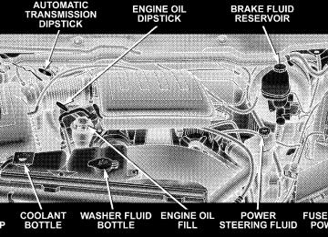
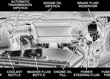
ENGINE COMPARTMENT— 5.7L
ONBOARD DIAGNOSTIC SYSTEM (OBD II) Your vehicle is equipped with a sophisticated onboard diagnostic system called OBDII. This system monitors the performance of the emissions, engine, and automatic transmission control systems. When these systems are operating properly, your vehicle will provide excellent performance and fuel economy, as well as engine emis- sions well within current government regulations. If any of these systems require service, the OBD II system will turn on the Malfunction Indicator Light (MIL). It will also store diagnostic codes and other information to assist your service technician in making repairs. Al- though your vehicle will usually be drivable and not need towing, see your authorized dealer for service as soon as possible.
MAINTAINING YOUR VEHICLE 447
CAUTION!
Prolonged driving with the Malfunction Indicator Light (MIL) on could cause further damage to the emission control system. It could also affect fuel economy and drivability. The vehicle must be ser- viced before any emissions tests can be performed. If the Malfunction Indicator Light (MIL) is flashing, severe catalytic converter damage and power loss will soon occur. Immediate service is required.
Loose Fuel Filler Cap Message
If the vehicle’s diagnostic system determines that the fuel filler cap in loose, improperly installed, or damaged, a GASCAP message will be displayed in the instrument cluster. Tighten the gas cap until a “clicking” sound is heard. This is an indication that the gas cap is properly
448 MAINTAINING YOUR VEHICLE
tightened. Press the odometer reset button to turn the message off. If the problem persists, the message will appear the next time the vehicle is started. This might indicate a damaged cap. If the problem is detected twice in a row, turn on the Malfunction Indicator Light (MIL). Resolving the problem will turn the MIL light off.
the system will
EMISSIONS INSPECTION AND MAINTENANCE PROGRAMS In some localities, it may be a legal requirement to pass an inspection of your vehicle’s emissions control system. Failure to pass could prevent vehicle registration.
For states which have an Inspection and Mainte- nance (I/M) requirement, this check verifies the following: the Malfunction Indicator Lamp (MIL) is functioning and is not on when the engine is running, and that the On Board Diagnostic (OBD) system is ready for testing.
Normally, the OBD system will be ready. The OBD system may not be ready if your vehicle was recently serviced, if you recently had a dead battery, or a battery replacement. If the OBD system should be determined not ready for the I/M test, your vehicle may fail the test. Your vehicle has a simple ignition key actuated test which you can use prior to going to the test station. To check if your vehicle’s OBD system is ready, you must do the following: 1. Insert your ignition key into the ignition switch. 2. Turn the ignition to the ON position, but do not crank or start the engine. 3. If you crank or start the engine, you will have to start this test over. 4. As soon as you turn your key to the ON position, you will see your MIL symbol come on as part of a normal bulb check.
MAINTAINING YOUR VEHICLE 449
Regardless of whether your vehicle’s OBD system is ready or not ready, if the MIL symbol is illuminated during normal vehicle operation, you should have your vehicle serviced before going to the I/M station. The I/M station can fail your vehicle because the MIL symbol is on with the engine running.
REPLACEMENT PARTS Use of genuine Mopart parts for normal/scheduled maintenance and repairs is highly recommended to en- sure the designed performance. Damage or failures caused by the use of non-Mopart parts for maintenance and repairs will not be covered by the manufacturer’s warranty.
5. Approximately 15 seconds later, one of two things will happen:
a. The MIL will blink for approximately five seconds and then remain on until the first engine crank or the key is turned off. This means that your vehicle’s OBD system is not ready and you should not proceed to the I/M station. b. The MIL will remain fully illuminated until the first engine crank or the key is turned off. This means that your vehicle’s OBD system is ready and you can proceed to the I/M station.
If your OBD system is not ready, you should see your authorized dealer or repair facility. If your vehicle was recently serviced, or had a battery failure or replacement, you may need to do nothing more than drive your vehicle as you normally would in order for your OBD system to update. A recheck with the above test routine may then indicate that the system is now ready.
450 MAINTAINING YOUR VEHICLE
AUTHORIZED DEALER SERVICE Your authorized dealer has the qualified service person- nel, special tools and equipment to perform all service operations in an expert manner. Service manuals are available which include detailed service information for your vehicle. Refer to these manuals before attempting any procedure yourself. NOTE: systems can result against you.
Intentional tampering with emissions control in civil penalties being assessed
WARNING!
You can be badly injured working on or around a motor vehicle. Do only that service work for which you have the knowledge and the proper equipment. If you have any doubt about your ability to perform a service job, take your vehicle to a competent mechanic.
MAINTENANCE PROCEDURES The pages that follow contain the required maintenance services determined by the engineers who designed your vehicle. Besides the maintenance items for which there are fixed maintenance intervals, there are other items that should operate satisfactorily without periodic maintenance. However, if a malfunction of these items does occur, it could adversely affect the engine or vehicle performance. These items should be inspected if a malfunction is observed or suspected.
Engine Oil
Checking Oil Level To assure proper lubrication of your vehicle’s engine, the engine oil must be maintained at the correct level. The best time to check the engine oil level is about five minutes after a fully warmed up engine is shut off or before starting the engine after it has sat overnight. Checking the oil while the vehicle is on level ground will improve the accuracy of the oil level readings. Always maintain the oil level within the SAFE zone on the dipstick. Adding one quart of oil when the reading is at the bottom of the SAFE zone will result in a reading at the top of the safe zone on these engines.
MAINTAINING YOUR VEHICLE 451
CAUTION!
Overfilling or underfilling the crankcase will cause oil aeration or loss of oil pressure. This could damage your engine.
452 MAINTAINING YOUR VEHICLE
Change Engine Oil Follow the Maintenance Schedule for recommended en- gine oil change intervals. Engine Oil Selection For best performance and maximum protection under all types of operating conditions, the manufacturer only recommends engine oils that are API-certified and meet the requirements of DaimlerChrysler Material Standard MS-6395.
American Petroleum Institute (API) Engine Oil Identification Symbol
This symbol means that the oil has been certified by the American Petroleum Institute (API). The manufacturer only recommends API-Certified engine oils.
Engine Oil Viscosity (SAE Grade) SAE 5W-20 engine oil is recommended for all operating temperatures. This engine oil improves low temperature starting and vehicle fuel economy. The engine oil filler cap also shows the recommended engine oil viscosity for your engine. For information on engine oil filler cap location, refer to the “Engine Compartment” illustration in this section.
NOTE: Vehicles equipped with a 5.7L engine must use SAE 5W-20 oil. Failure to do so may result in improper operation of the Multi-Displacement System (MDS). Re- fer to “Multi-Displacement System” under “Starting and Operating” in Section 5. NOTE: For 2500/3500 trucks with a 5.7L engine oper- ating under a gross combined weight rating of 14,000 lbs. or greater, SAE 5W-30 engine oil is recommended for all operating temperatures. Lubricants, which do not have both the engine oil certi- fication mark and the correct SAE viscosity grade num- ber, should not be used. Synthetic Engine Oils You may use synthetic engine oils if the recommended oil quality requirements are met, and the recommended maintenance intervals for oil and filter changes are followed.
MAINTAINING YOUR VEHICLE 453
Materials Added to Engine Oil The manufacturer strongly recommends against the ad- dition of any additives (other than leak detection dyes) to the engine oil. Engine oil is an engineered product and its performance may be impaired by supplemental addi- tives. Disposing of Used Engine Oil and Oil Filters Care should be taken in disposing of used engine oil and oil filters from your vehicle. Used oil and oil filters, indiscriminately discarded, can present a problem to the environment. Contact your authorized dealer, service station, or governmental agency for advice on how and where used oil and oil filters can be safely discarded in your area.
454 MAINTAINING YOUR VEHICLE
Engine Oil Filter The engine oil filter should be replaced at every engine oil change. Engine Oil Filter Selection The manufacturer’s engines have a full-flow type oil filter. Use a filter of this type for replacement. The quality of replacement filters varies considerably. Only high- quality filters should be used to assure most efficient service. Mopar Engine Oil Filters are a high-quality oil filter and are recommended. Drive Belts — Check Condition and Tension Belt tension is controlled by means of an automatic tensioner. No belt tension adjustments are required. However, belt and belt tensioner condition should be inspected at the specified intervals and replaced if re- quired. See your authorized dealer for service.
At the mileage indicated in the maintenance schedule, all belts and tensioner should be checked for condition. Improper belt tension can cause belt slippage and failure. Belts should be inspected for evidence of cuts, cracks, glazing or frayed cords and replaced if there is indication of damage which could result in belt failure. Low gen- erator belt tension can cause battery failure. Also check belt routing to make sure there is no interfer- ence between the belts and other engine components. Spark Plugs (Gas Engines) Spark plugs must fire properly to assure engine perfor- mance and emission control. New plugs should be in- stalled at the specified mileage. The entire set should be replaced if there is any malfunction due to a faulty spark plug. Malfunctioning spark plugs can damage the cata- lytic converter. For proper type of replacement spark plugs, refer to the “Spark Plugs” under “Fluids, Lubri- cants and Genuine Parts” in Section 7.
Engine Air Cleaner Filter Follow the Maintenance Schedule for recommended En- gine Air Cleaner Filter change intervals.
WARNING!
The air induction system (air cleaner, hoses, etc.) can provide a measure of protection in the case of engine backfire. Do not remove the air induction system (air cleaner, hoses, etc.) unless such removal is necessary for repair or maintenance. Make sure that no one is near the engine compartment before starting the vehicle with the air induction system (air cleaner, hoses, etc.) removed. Failure to do so can result in serious personal injury.
MAINTAINING YOUR VEHICLE 455
Engine Fuel Filter A plugged fuel filter can cause stalling, limit the speed at which a vehicle can be driven or cause hard starting. Should an excessive amount of dirt accumulate in the fuel tank, frequent filter replacement may be necessary. Catalytic Converter The catalytic converter requires the use of unleaded fuel only. Leaded gasoline will destroy the effectiveness of the catalyst as an emission control device. Under normal operating conditions, the catalytic con- verter will not require maintenance. However, it is im- portant to keep the engine properly tuned to assure proper catalyst operation and prevent possible catalyst damage.
456 MAINTAINING YOUR VEHICLE
CAUTION!
WARNING!
Damage to the catalytic converter can result if your vehicle is not kept in proper operating condition. In the event of engine malfunction, particularly involv- ing engine misfire or other apparent loss of perfor- mance, have your vehicle serviced promptly. Contin- ued operation of your vehicle with a severe malfunction could cause the converter to overheat, resulting in possible damage to the converter and the vehicle.
NOTE: systems can result against you.
Intentional tampering with emissions control in civil penalties being assessed
A hot exhaust system can start a fire if you park over materials that can burn. Such materials might be grass or leaves coming into contact with your exhaust system. Do not park or operate your vehicle in areas where your exhaust system can contact anything that can burn.
In unusual situations involving grossly malfunctioning engine operation, a scorching odor may indicate severe and abnormal catalyst overheating. If this occurs, the vehicle should be stopped, the engine shut off and the vehicle allowed to cool. Thereafter, service, including a tune-up to manufacturer’s specifications, should be ob- tained immediately.
To minimize the possibility of catalyst damage: † Do not shut off the engine or interrupt the ignition when the transmission is in gear and the vehicle is in motion. † Do not try to start the engine by pushing or towing the † Do not idle the engine with any spark plug wires disconnected or removed, such as when diagnostic testing, or for prolonged periods during very rough idling or malfunctioning operating conditions.
vehicle.
MAINTAINING YOUR VEHICLE 457
Emission-Related Components
the intervals specified.
Positive Crankcase Valve (PCV) Proper operation of the crankcase ventilation system requires that the PCV valve be free of sticking or plug- ging from deposits. Deposits can accumulate in the PCV valve and passages with increasing mileage. Have the PCV valve, hoses, and passages checked for proper operation at the valve is plugged or sticking, replace with a new valve— do not attempt to clean the old PCV valve! Check the ventila- tion hoses for indications of damage, weepage or plug- ging with deposits. Replace if necessary. Maintenance-Free Battery The top of the maintenance-free battery is permanently sealed. You will never have to add water, nor is periodic maintenance required.
If
458 MAINTAINING YOUR VEHICLE
WARNING!
† Battery fluid is a corrosive acid solution and can burn or even blind you. Don’t allow battery fluid to contact your eyes, skin or clothing. Don’t lean over a battery when attaching clamps. If acid splashes in eyes or on skin, flush the area imme- diately with large amounts of water. † Battery gas is flammable and explosive. Keep flame or sparks away from the battery. Don’t use a booster battery or any other booster source with an output greater than 12 volts. Don’t allow cable clamps to touch each other. † Battery posts, terminals and related accessories contain lead and lead compounds. Wash hands after handling.
CAUTION!
† It is essential when replacing the cables on the battery that the positive cable is attached to the positive post and the negative cable is attached to the negative post. Battery posts are marked (+) positive and (-) negative and identified on the battery case. † If a “fast charger” is used while the battery is in the vehicle, disconnect both vehicle battery cables before connecting the charger to the battery. Do not use a “fast charger” to provide starting voltage.
Air Conditioner Maintenance For best possible performance, your air conditioner should be checked and serviced by an Authorized Dealer at the start of each warm season. This service should include cleaning of the condenser fins and a performance test. Drive belt tension should also be checked at this time. NOTE: Refer to Section 3 of the Warranty Information book for further warranty information.
MAINTAINING YOUR VEHICLE 459
WARNING!
† Use only refrigerants and compressor lubricants approved by the manufacturer for your air condi- tioning system. Some unapproved refrigerants are flammable and can explode, injuring you. Other unapproved refrigerants or lubricants can cause the system to fail, requiring costly repairs. † The air conditioning system contains refrigerant under high pressure. To avoid risk of personal injury or damage to the system, adding refrigerant or any repair requiring lines to be disconnected should be done by an experienced repairman.
NOTE: Use only manufacturer approved A/C System Sealers, Stop Leak Products, Seal Conditioners, Compres- sor Oil, or Refrigerants.
460 MAINTAINING YOUR VEHICLE
Refrigerant Recovery and Recycling R-134a Air Conditioning Refrigerant is a hydrofluoro- carbon (HFC) that is endorsed by the Environmental Protection Agency (EPA) and is an ozone-saving product. However, the manufacturer recommends that air condi- tioning service be performed by authorized dealers or other service facilities using recovery and recycling equipment. Power Steering — Fluid Check Checking the power steering fluid level at a defined service interval is not required. The fluid should only be checked if a leak is suspected, abnormal noises are apparent, and/or the system is not functioning as antici- pated. Coordinate inspection efforts through an autho- rized dealer.
WARNING!
Fluid level should be checked on a level surface and with the engine off to prevent injury from moving parts and to ensure accurate fluid level reading. Do not overfill. Use only manufacturers recommended power steering fluid.
If necessary, add fluid to restore to the proper indicated level. With a clean cloth, wipe any spilled fluid from all surfaces. Refer to “Fluids, Lubricants, and Genuine Parts” in this section for correct fluid type. Front Suspension Ball Joints
4 x 2 Models The ball joints and seals should be inspected whenever the vehicle is serviced for other reasons.
if the seals on the ball
The ball joints originally supplied with the vehicle are permanently lubricated at the factory and do not require service. However, joints are the joints should be replaced. Serviceable damaged, replacement ball joints are available. Front suspension ball joints should be replaced only by a qualified service technician using tools specially de- signed for this purpose. Damage to the joints and/or suspension components may result if improper replace- ment procedures are used. If seals are damaged the ball joints should be replaced to prevent leakage or contamination of the grease. Steering Linkage — Inspection Whenever the vehicle is hoisted, all steering linkage joints should be inspected for evidence of damage. If seals are damaged, parts should be replaced to prevent
MAINTAINING YOUR VEHICLE 461
leakage or contamination of the grease. Lubricate the steering linkage regularly according to the “Maintenance Schedule” in this manual. Half-shaft Constant Velocity Joints All four-wheel drive 1500 models are equipped with four constant velocity joints. Periodic lubrication of these joints is not required. However, the joint boots should be inspected for external leakage or damage, periodically. If external leakage or damage is evident, the joint boot and grease should be replaced immediately. Continued op- eration could result in failure of the joint due to water and dirt contamination of the grease. This would require complete replacement of the joint assembly. Refer to the Service Manual for the detailed replacement procedure.
462 MAINTAINING YOUR VEHICLE
Front Prop Shaft Lubrication — 2500/3500 (4X4) Models Lubricate the front driveshaft grease fitting at each oil change listed in the appropriate Maintenance Schedule for your vehicle. Use Mopart type MS-6560 (lithium- based grease), or equivalent.
Front Driveshaft Grease Fitting
Body Lubrication
Locks and all body pivot points, including such items as seat tracks, doors, liftgate, tailgate, sliding doors and hood hinges, should be lubricated periodically to assure quiet, easy operation and to protect against rust and wear. Prior to the application of any lubricant, the parts concerned should be wiped clean to remove dust and grit. After lubricating, excess oil and grease should be removed. Particular attention should also be given to hood latching components to ensure proper function. When performing other underhood services, the hood latch, release mechanism and safety catch should be cleaned and lubricated. The external lock cylinders should be lubricated twice a year, preferably in the Fall and Spring. Apply a small amount of a high-quality lubricant such as Mopart Lock Cylinder Lubricant di- rectly into the lock cylinder.
Windshield Wiper Blades The rubber edges of the wiper blades and the windshield should be cleaned periodically with a sponge or soft cloth and a mild nonabrasive cleaner. This will remove accu- mulations of salt or road film. Operation of the wipers on dry glass for long periods may cause deterioration of the wiper blades. Always use washer fluid when using the wipers to remove salt or dirt from a dry windshield. Avoid using the wiper blades to remove frost or ice from the windshield. Keep the blade rubber out of contact with petroleum products such as engine oil, gasoline, etc. Windshield Washers The fluid reservoir is located under the hood and should be checked for fluid level at regular intervals. Fill the
MAINTAINING YOUR VEHICLE 463
reservoir with windshield washer solvent only (not ra- diator antifreeze). When refilling the washer fluid reser- voir, take some washer fluid and apply it to a cloth or towel and wipe clean the wiper blades, this will help blade performance. To prevent freeze-up of your windshield washer system in cold weather, select a solution or mixture that meets or exceeds the temperature range of your climate. This rating information can be found on most washer fluid containers. The washer fluid reservoir will hold a full gallon of fluid when the Low Washer Fluid Light illuminates.
464 MAINTAINING YOUR VEHICLE
WARNING!
Commercially available windshield washer solvents are flammable. They could ignite and burn you. Care must be exercised when filling or working around the washer solution.
After the engine has warmed, operate the defroster for a few minutes to reduce the possibility of smearing or freezing the fluid on the cold windshield. Mopart All Weather Windshield Washer Solution, used with water as directed on the container, aids cleaning action, reduces the freezing point to avoid line clogging, and is not harmful to paint or trim.
Exhaust System The best protection against carbon monoxide entry into the vehicle body is a properly maintained engine exhaust system. Whenever a change is noticed in the sound of the exhaust system, when exhaust fumes can be detected inside the vehicle, or when the underside or rear of the vehicle is damaged, have a competent mechanic inspect the com- plete exhaust system and adjacent body areas for broken, damaged, deteriorated, or mispositioned parts. Open