- Download PDF Manual
-
REAR BRAKE GRAB OR PULL
Rear grab or pull is usually caused by improperly adjusted or seized parking brake cables, contami- nated lining, bent or binding shoes and support plates, or improperly assembled components. This is particularly true when only one rear wheel is involved. However, when both rear wheels are affected, the master cylinder or proportioning valve could be at fault.
BRAKES DO NOT HOLD AFTER DRIVING THROUGH DEEP WATER PUDDLES
This condition is generally caused by water soaked lining. If the lining is only wet, it can be dried by driving with the brakes very lightly applied for a mile or two. However, if the lining is both soaked and dirt contaminated, cleaning and/or replacement will be necessary.
BRAKE LINING CONTAMINATION
Brake lining contamination is mostly a product of leaking calipers or wheel cylinders, worn seals, driv- ing through deep water puddles, or lining that has
DR
become covered with grease and grit during repair. Contaminated lining should be replaced to avoid fur- ther brake problems.
WHEEL AND TIRE PROBLEMS
Some conditions attributed to brake components may actually be caused by a wheel or tire problem. A damaged wheel can cause shudder, vibration and
pull. A worn or damaged tire can also cause pull.
Severely worn tires with very little tread left can produce a grab-like condition as the tire loses and recovers traction. Flat-spotted tires can cause vibra- tion and generate shudder during brake operation. A tire with internal damage such as a severe bruise, cut, or ply separation can cause pull and vibration.
BRAKE NOISES
Some brake noise is common with rear drum brakes and on some disc brakes during the first few stops after a vehicle has been parked overnight or stored. This is primarily due to the formation of trace corrosion (light rust) on metal surfaces. This light corrosion is typically cleared from the metal surfaces after a few brake applications causing the noise to subside.
BRAKE SQUEAK/SQUEAL
Brake squeak or squeal may be due to linings that are wet or contaminated with brake fluid, grease, or oil. Glazed linings and rotors with hard spots can also contribute to squeak. Dirt and foreign material embedded in the brake lining will also cause squeak/ squeal.
A very loud squeak or squeal is frequently a sign of severely worn brake lining. If the lining has worn through to the brake shoes in spots, metal-to-metal contact occurs. If the condition is allowed to continue, rotors and drums can become so scored that replace- ment is necessary.
BRAKE CHATTER
Brake chatter is usually caused by loose or worn components, or glazed/burnt lining. Rotors with hard spots can also contribute to chatter. Additional causes of chatter are out-of-tolerance rotors, brake lining not securely attached to the shoes, loose wheel bearings and contaminated brake lining.
THUMP/CLUNK NOISE
Thumping or clunk noises during braking are fre- quently not caused by brake components. In many cases, such noises are caused by loose or damaged steering, suspension, or engine components. However, calipers that bind on the slide surfaces can generate a thump or clunk noise. In addition, worn out, improperly adjusted, or improperly assembled rear brake shoes can also produce a thump noise.
DR BRAKES - BASE (Continued) STANDARD PROCEDURE
STANDARD PROCEDURE - MANUAL BLEEDING Use Mopar brake fluid, or an equivalent quality fluid meeting SAE J1703-F and DOT 3 standards only. Use fresh, clean fluid from a sealed container at all times.
(1) Remove reservoir filler caps and fill reservoir. (2) If calipers, or wheel cylinders were overhauled, open all caliper and wheel cylinder bleed screws. Then close each bleed screw as fluid starts to drip from it. Top off master cylinder reservoir once more before proceeding.
(3) Attach one end of bleed hose to bleed screw and insert opposite end in glass container partially filled with brake fluid (Fig. 1). Be sure end of bleed hose is immersed in fluid.
BRAKES - BASE
5 - 5
tank manufacturers pressure recommendations. Gen- erally, a tank pressure of 15-20 psi is sufficient for bleeding.
Fill the bleeder tank with recommended fluid and
purge air from the tank lines before bleeding.
Do not pressure bleed without a proper master cyl- inder adapter. The wrong adapter can lead to leak- age, or drawing air back into the system.
SPECIAL TOOLS
BASE BRAKES
INSTALLER,BRAKECALIPERDUSTBOOTC-4340
INSTALLER,BRAKECALIPERDUSTBOOT
C-3716-A
Fig.1BleedHoseSetup
1 - BLEED HOSE 2 - FLUID CONTAINER PARTIALLY FILLED WITH FLUID
(4) Open up bleeder, then have a helper press down the brake pedal. Once the pedal is down close the bleeder. Repeat bleeding until fluid stream is clear and free of bubbles. Then move to the next wheel.
STANDARD PROCEDURE - PRESSURE BLEEDING
Use Mopar brake fluid, or an equivalent quality fluid meeting SAE J1703-F and DOT 3 standards only. Use fresh, clean fluid from a sealed container at all times.
Follow the manufacturers instructions carefully when using pressure equipment. Do not exceed the
HANDLEC-4171
BRAKES - BASE
5 - 6
BRAKES - BASE (Continued)DR
CAP,MASTERCYLINDERPRESSUREBLEED6921
GAUGE,BRAKESAFE-SETC-3919
ADJUSTABLE PEDAL SWITCH REMOVAL
(1) Remove the lower drivers side bezel (Refer to 23 - BODY/INSTRUMENT PANEL/INSTRUMENT PANEL DR SIDE BEZEL - REMOVAL).
(2) Disconnect the electrical connector from the
adjustable pedal switch.
(3) Remove the switch from the lower drivers side bezel by squeezing the retaining clips together and pushing the switch outwards (Fig. 2).
INSTALLATION
(1) Install the switch to the lower drivers side bezel by pushing the switch inwards seating the retaining clips to the lower drivers side bezel.
Fig.2LOWERDRIVERSSIDEBEZEL
1 - SCREWS (2) 2 - ADJUSTABLE PEDAL SWITCH 3 - PEDAL SWITCH ELECTRICAL CONNECTOR 4 - BEZEL
(2) Reconnect
the
electrical
connector
to
the
adjustable pedal switch.
(3) Install the lower drivers side bezel
(Fig. 2) (Refer to 23 - BODY/INSTRUMENT PANEL/IN- STRUMENT PANEL DR SIDE BEZEL - INSTALLA- TION).
HYDRAULIC/MECHANICAL
SPECIFICATIONS
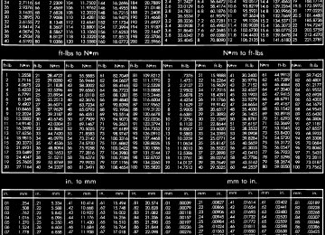
SPECIFICATIONS - TORQUE CHART
TORQUE SPECIFICATIONS
DESCRIPTION Brake Booster Mounting Nuts Master Cylinder Mounting Nuts
Caliper
Mounting Pins
Caliper
Adapter Mounting Bolts
Junction Block Bolts To Frame
Brake Pedal Assembly Bracket
Nuts
N·m 38
18
32
176
10
28
Ft. Lbs.
28
—
24
130
7.5
21
In. Lbs.
—
160
—
—
—
—
DR HYDRAULIC/MECHANICAL (Continued)
DESCRIPTION Support Plate
Mounting Bolts/Nuts Brake Line Fittings
Master Cylinder
Brake Line Fittings
Junction Block
Caliper
Brake Line Banjo Bolt
Brake Hose
Front Bolts To Frame
Brake Hose Front Fitting Brake Hose Rear Fitting
Parking Brake Pedal Assembly
Hub/Bearing
Bolts
N·m 64
19
19
27
10
19
19
19
163BRAKES - BASE
5 - 7
Ft. Lbs.
In. Lbs.
47
14
14
20
7.5
14
14
14
120—
170
170
245
—
250
250
250
—BASE BRAKE
BRAKE LINES
SPECIFICATIONS
DESCRIPTION
SPECIFICATION
Front Disc Brake Caliper Type Rear Disc Brake Caliper Type Front Disc Brake Caliper Front Disc Brake Rotor
Front/Rear Disc Brake Rotor Max. Runout Front/Rear Disc Brake Rotor Max. Thickness Variation Minimum Front Rotor Thickness Mininium Rear Rotor Thickness Rear Disc Brake Caliper Rear Disc Brake Rotor Brake Booster Type Gasoline Engines
Dual Piston Sliding
Single Piston Sliding
54 mm (2.00 in.) 336×28 mm (13.2×1.1
in.) 0.127 mm (0.005 in.)0.025 mm (0.001 in.)
26.4 mm (1.039 in.)
28.39 mm (1.117 in)
1x54 mm (2.12 in) 350x22 mm (.86 in) Vacuum Dual Diaphragm
STANDARD PROCEDURE
STANDARD PROCEDURE - DOUBLE INVERTED FLARING
A preformed metal brake tube is recommended and preferred for all repairs. However, double-wall steel tube can be used for emergency repair when factory replacement parts are not readily available.
(1) Cut off damaged tube with Tubing Cutter. (2) Ream cut edges of tubing to ensure proper
flare.
(3) Install replacement tube nut on the tube. (4) Insert tube in flaring tool. (5) Place gauge form over the end of the tube. (6) Push tubing through flaring tool
jaws until tube contacts recessed notch in gauge that matches tube diameter.
(7) Tighten the tool bar on the tube (8) Insert plug on gauge in the tube. Then swing compression disc over gauge and center tapered flar- ing screw in recess of compression disc (Fig. 3).
(9) Tighten tool handle until plug gauge
is squarely seated on jaws of flaring tool. This will start the inverted flare.
(10) Remove the plug gauge and complete the
inverted flare.
STANDARD PROCEDURE - ISO FLARING
A preformed metal brake tube is recommended and preferred for all repairs. However, double-wall steel
BRAKES - BASE
5 - 8
BRAKE LINES (Continued)DR
Fig.3InvertedFlareTools
tube can be used for emergency repair when factory replacement parts are not readily available.
To make a ISO flare use an ISO flaring tool kit. (1) Cut off damaged tube with Tubing Cutter. (2) Remove any burrs from the inside of the tube. (3) Install tube nut on the tube. (4) Position the tube in the flaring tool flush with the top of the tool bar (Fig. 4). Then tighten the tool bar on the tube.
(5) Install the correct size adaptor on the flaring
tool yoke screw.
(6) Lubricate the adaptor. (7) Align the adaptor and yoke screw over the tube
(Fig. 4).
(8) Turn the yoke screw in until the adaptor is
squarely seated on the tool bar.
REMOVAL
REMOVAL - REAR BRAKE HOSE
(1) Install prop rod on the brake pedal to keep
pressure on the brake system.
(2) Raise and support the vehicle. (3) Remove the brake line from the hose at the
frame (Fig. 5).
(4) Remove the brake hose clip at the top of the
hose located at the frame (Fig. 5).
(5) Remove the vent tube (Fig. 6). (6) Remove the two brake lines at the bottom of
the hose located at the axle (Fig. 6).
(7) Remove the mounting bolt for the brake hose
at the axle (Fig. 6).
(8) Remove the hose.
Fig.4ISOFlaring
1 - ADAPTER 2 - LUBRICATE HERE 3 - PILOT 4 - FLUSH WITH BAR 5 - TUBING 6 - BAR ASSEMBLY
Fig.5BRAKELINECLIP
1 - BRAKE HOSE 2 - CLIP 3 - BRAKE LINE
REMOVAL - REAR TUBE / HOSE ASSEMBLY
(1) Install prop rod on the brake pedal to keep
pressure on the brake system.
(2) Raise and support the vehicle. (3) Remove the brake line located at the axle. (4) Remove the mounting bolt for the brake hose
at the axle (Fig. 7).
DR BRAKE LINES (Continued)
BRAKES - BASE
5 - 9
Fig.6REARHOSE
1 - BRAKE HOSE 2 - VENT HOSE 3 - BRAKE LINES
Fig.8BRAKEHOSEMOUNTEDPASSENGERSIDE 1 - MOUNTING BOLT 2 - BRAKE HOSE 3 - BANJO BOLT 4 - WHEEL SPEED SENSOR WIRE
(5) Remove the banjo bolt at the caliper (Fig. 7). (6) Remove the hose.
INSTALLATION
INSTALLATION - REAR BRAKE HOSE
(1) Install the hose. (2) Install the mounting bolt for the brake hose at
the axle (Fig. 6).
(3) Install the two brake lines at the bottom of the
hose located at the axle (Fig. 6).
(4) Install the vent tube (Fig. 6). (5) Install the brake hose clip at the top of the
hose located at the frame (Fig. 5).
(6) Install the brake line to the hose at the frame
(Fig. 5).
(7) Lower the vehicle and remove the support. (8) Remove the prop rod. (9) Bleed the brake system (Refer to 5 - BRAKES -
STANDARD PROCEDURE).
INSTALLATION - REAR TUBE / HOSE ASSEMBLY
(1) Install the hose. (2) Install the banjo bolt at the caliper (Fig. 7). (3) Install the mounting bolt for the brake hose at
(4) Install the brake line located at the axle. (5) Lower the vehicle and remove the support. (6) Remove the prop rod. (7) Bleed the brake system (Refer to 5 - BRAKES -
STANDARD PROCEDURE).
INSTALLATION - FRONT BRAKE HOSE
(1) Install the hose. (2) Install the mounting bolt for the brake hose at
the frame (Fig. 9).
(1) Install a prop rod on the brake pedal to keep
the axle (Fig. 7).
Fig.7BRAKELINEWITHRUBBERHOSE
1 - BANJO BOLT 2 - MOUNTING BOLT 3 - REAR TUBE / HOSE ASSEMBLY
REMOVAL - FRONT HOSE
pressure on the brake system.
(2) Raise and support vehicle. (3) Remove the tire and wheel assembly. (4) Remove the brake hose from the brake line
located at the frame (Fig. 8).
(5) Remove the brake hose banjo bolt at the caliper
(Fig. 8).
(6) Remove the mounting bolt securing the brake hose to the frame and remove the wheel speed sensor wire from the brake hose (Fig. 8).
(7) Remove the hose.
BRAKES - BASE
5 - 10
BRAKE LINES (Continued)DR
(3) Install the brake hose banjo bolt at the caliper
(Fig. 8).
brake hose (Fig. 8).
(4) Reinstall the wheel speed sensor wire to the
(5) Remove the support and lower the vehicle.
Fig.10Caliper
1 - CALIPER 2 - CALIPER ADAPTER
Fig.9BRAKEHOSEMOUNTDRIVERSSIDE
1 - MOUNTING BOLT 2 - WHEEL SPEED SENSOR WIRE 3 - BRAKE HOSE
(6) Remove the prop rod from the brake pedal. (7) Bleed the brake system (Refer to 5 - BRAKES -
STANDARD PROCEDURE).
BRAKE PADS/SHOES REMOVAL
(1) Raise and support vehicle. (2) Remove the wheel and tire assemblies. (3) Compress the caliper. (4) Remove the caliper, (Refer to 5 - BRAKES/HY- DRAULIC/MECHANICAL/DISC BRAKE CALIPERS - REMOVAL).
(5) Remove the caliper by tilting the top up and off
the caliper adapter (Fig. 10).
Fig.11DISCBRAKECALIPER-FRONT
1 - STEERING KNUCKLE 2 - DISC BRAKE CALIPER 3 - CALIPER MOUNTING ADAPTER 4 - DISC BRAKE ROTOR
NOTE: Do not allow brake hose to support caliper assembly.
INSTALLATION
(6) Support and hang the caliper. (Fig. 11) (7) Remove the inboard brake shoe from the cali-
per adapter (Fig. 12).
per adapter (Fig. 13).
(8) Remove the outboard brake shoe from the cali-
(9) Remove the anti-rattle springs from the caliper
adapter (Fig. 14) and (Fig. 15).
(1) Bottom pistons in caliper bore with C-clamp. Place an old brake shoe between a C-clamp and cal- iper piston.
(2) Clean caliper mounting adapter and anti-rattle
(3) Lubricate anti-rattle springs with Mopar brake
springs.
grease.
(4) Install anti-rattle springs.
NOTE: Anti-rattle springs are not interchangeable.
NOTE: Anti-rattle springs are not interchangeable.
(5) Install inboard brake shoe in adapter.
DR BRAKE PADS/SHOES (Continued)
BRAKES - BASE
5 - 11
Fig.14TopAnti-RattleSpring
1 - CALIPER ADAPTER 2 - ANTI-RATTLE SPRING
Fig.12InboardBrakeShoe
1 - INBOARD SHOE 2 - CALIPER ADAPTER
Fig.15BottomAnti-RattleSpring
1 - ANTI-RATTLE SPRING 2 - CALIPER ADAPTER
Fig.13OutboardBrakeShoe
1 - OUTBOARD SHOE 2 - CALIPER ADAPTER
(6) Install outboard brake shoe in adapter. (7) Tilt the top of the caliper over rotor and under adapter. Then push the bottom of the caliper down onto the adapter.
(8) Install caliper,
(Refer to 5 - BRAKES/HY- DRAULIC/MECHANICAL/DISC BRAKE CALIPERS - INSTALLATION).
(9) Install wheel and tire assemblies and lower vehicle, (Refer to 22 - TIRES/WHEELS/WHEELS - STANDARD PROCEDURE).
(10) Apply brakes several times to seat caliper pis-
tons and brake shoes and obtain firm pedal.
(11) Top off master cylinder fluid level.
DISC BRAKE CALIPERS DESCRIPTION
The calipers are a single piston type in the rear and dual piston type in the front. The calipers are free to slide laterally, this allows continuous compen- sation for lining wear.
BRAKES - BASE
5 - 12
DISC BRAKE CALIPERS (Continued) OPERATIONWhen the brakes are applied fluid pressure is exerted against the caliper piston. The fluid pressure is exerted equally and in all directions. This means pressure exerted against the caliper piston and within the caliper bore will be equal (Fig. 16).
Fig.16BrakeCaliperOperation
1 - CALIPER 2 - PISTON 3 - PISTON BORE 4 - SEAL 5 - INBOARD SHOE 6 - OUTBOARD SHOE
Fluid pressure applied to the piston is transmitted directly to the inboard brake pad. This forces the pad lining against the inner surface of the disc brake rotor. At the same time, fluid pressure within the pis- ton bore forces the caliper to slide inward on the mounting bolts. This action brings the outboard brake pad lining into contact with the outer surface of the disc brake rotor.
In summary, fluid pressure acting simultaneously on both piston and caliper, produces a strong clamp- ing action. When sufficient force is applied, friction will attempt to stop the rotors from turning and bring the vehicle to a stop.
Application and release of the brake pedal gener- ates only a very slight movement of the caliper and piston. Upon release of the pedal, the caliper and pis- ton return to a rest position. The brake pads do not retract an appreciable distance from the rotor. In fact, clearance is usually at, or close to zero. The rea- sons for this are to keep road debris from getting
DR
between the rotor and lining and in wiping the rotor surface clear each revolution.
The caliper piston seal controls the amount of pis- ton extension needed to compensate for normal lining wear.
During brake application, the seal is deflected out- ward by fluid pressure and piston movement (Fig. 17). When the brakes (and fluid pressure) are released, the seal relaxes and retracts the piston.
The amount of piston retraction is determined by the amount of seal deflection. Generally the amount is just enough to maintain contact between the pis- ton and inboard brake pad.
Fig.17LiningWearCompensationByPistonSeal 1 - PISTON 2 - CYLINDER BORE 3 - PISTON SEAL BRAKE PRESSURE OFF 4 - CALIPER HOUSING 5 - DUST BOOT 6 - PISTON SEAL BRAKE PRESSURE ON
REMOVAL
REMOVAL - REAR
(1) Install prop rod on the brake pedal to keep
pressure on the brake system.
(2) Raise and support vehicle. (3) Remove the wheel and tire assembly. (4) Drain small amount of fluid from master cylin-
der brake reservoir with suction gun.
(5) Remove the brake hose banjo bolt if replacing
(6) Remove the caliper mounting slide pin bolts
caliper (Fig. 18).
(Fig. 18).
(7) Remove the caliper from vehicle.
REMOVAL - FRONT
CAUTION: Never allow the disc brake caliper to hang from the brake hose. Damage to the brake hose with result. Provide a suitable support to hang the caliper securely.
(1) Install prop rod on the brake pedal to keep
pressure on the brake system.
DR DISC BRAKE CALIPERS (Continued)
BRAKES - BASE
5 - 13
Fig.18DISCBRAKECALIPER-REAR
Fig.208LUGROTOR&CALIPERASSEMBLY
1 - CALIPER ADAPTER 2 - CALIPER ADAPTER MOUNTING BOLTS 3 - CALIPER SLIDE BOLTS 4 - BRAKE HOSE 5 - CABLE 6 - CALIPER 7 - ROTOR 8 - ANTI-RATTLE CLIPS
(2) Raise and support the vehicle. (3) Remove the tire and wheel assembly. (4) Compress the disc brake caliper. (5) Remove the banjo bolt and discard the copper
(6) Remove the caliper slide pin bolts. (7) Remove the disc brake caliper (Fig. 19) or (Fig.
washer.
20).
1 - ROTOR 2 - CALIPER ADAPTER 3 - ANTI-RATTLE CLIPS 4 - BRAKE HOSE WITH BANJO BOLT 5 - DISC BRAKE CALIPER 6 - OUTBOARD BRAKE PAD
DISASSEMBLY
(1) Drain the brake fluid from caliper. (2) C-clamp a block of wood over one piston (Fig.
21).
Fig.19DISCBRAKECALIPER-FRONT
1 - STEERING KNUCKLE 2 - DISC BRAKE CALIPER 3 - CALIPER MOUNTING ADAPTER 4 - DISC BRAKE ROTOR
Fig.21C-ClampOnePiston
1 - BLOCK OF WOOD 2 - C-CLAMP 3 - CALIPER
(3) Take another piece of wood and pad it with one-inch thickness of shop towels. Place this piece in the outboard shoe side of the caliper in front of the other piston. This will cushion and protect caliper piston during removal (Fig. 22).
(4) To remove the caliper piston direct short bursts of low pressure air with a blow gun through the caliper brake hose port. Use only enough air pressure to ease the piston out.
BRAKES - BASE
5 - 14
DISC BRAKE CALIPERS (Continued)DR
Fig.23PistonDustBootRemoval
1 - CALIPER 2 - DUST BOOT
Fig.22ProtectCaliperPiston
1 - CALIPER 2 - PADDED BLOCK OF WOOD 3 - C-CLAMP
CAUTION: Do not blow the piston out of the bore with sustained air pressure. This could result in a cracked piston.
WARNING: NEVER ATTEMPT TO CATCH THE PIS- TON AS IT LEAVES THE BORE. THIS COULD RESULT IN PERSONAL INJURY.
(5) Remove the C-clamp and block of wood from the caliper and clamp it over the dust boot of the first piston removed. This will seal the empty piston bore.
(6) Move the padded piece of wood in front of the
other piston.
(7) Remove the second piston using the same pro-
cedure with short bursts of low pressure air.
(8) Remove piston dust boots with a suitable pry
tool (Fig. 23).
(9) Remove piston seals from caliper (Fig. 24).
CAUTION: Do not scratch piston bore while remov- ing the seals.
(10) Push caliper mounting bolt bushings out of the boot seals and remove the boot seals from the caliper (Fig. 25).
(11) Remove caliper bleed screw.
INSPECTION
The piston is made from a phenolic resin (plastic
material) and should be smooth and clean.
The piston must be replaced if cracked or scored. Do not attempt to restore a scored piston surface by sanding or polishing.
Fig.24PistonSeal
1 - CALIPER 2 - PISTON BORE 3 - PISTON SEAL
CAUTION: If the caliper piston is replaced, install the same type of piston in the caliper. Never inter- change phenolic resin and steel caliper pistons. The pistons, seals, seal grooves, caliper bore and piston tolerances are different.
The bore can be lightly polished with a brake hone to remove very minor surface imperfections (Fig. 26). The caliper should be replaced if the bore is severely corroded, rusted, scored, or if polishing would increase bore diameter more than 0.025 mm (0.001 inch).
DR DISC BRAKE CALIPERS (Continued)
BRAKES - BASE
5 - 15
Fig.25BushingsAndBootSeals
1 - CALIPER 2 - BUSHING 3 - BOOT SEAL
Fig.27PistonSeal
1 - CALIPER 2 - PISTON BORE 3 - PISTON SEAL
(4) Stretch boot rearward to straighten boot folds,
then move boot forward until folds snap into place.
(5) Install piston into caliper bore and press piston down to the bottom of the caliper bore by hand or with hammer handle (Fig. 28).
Fig.26PolishingPistonBore
1 - HONE 2 - CALIPER 3 - PISTON BORE
ASSEMBLY
CAUTION: Dirt, oil, and solvents can damage cali- per seals. Insure assembly area is clean and dry.
(1) Lubricate caliper pistons, piston seals and pis-
ton bores with clean, fresh brake fluid.
(2) Install new piston seals into caliper bores (Fig.
27).
NOTE: Verify seal is fully seated and not twisted.
(3) Lightly lubricate lip of new boot with silicone grease. Install boot on piston and work boot lip into the groove at the top of piston.
Fig.28CaliperPistonInstallation
1 - CALIPER 2 - DUST BOOT 3 - PISTON
C-4171 and Installer:
(6) Seat dust boot in caliper (Fig. 29) with Handle † HD 56 mm caliper: Installer C-4340
† LD 54 mm caliper: Installer C-3716-A (7) Install the second piston and dust boot. (8) Lubricate caliper mounting bolt bushings, boot seals and bores with Mopar brake grease or Dow Corningt 807 grease only.BRAKES - BASE
5 - 16
DISC BRAKE CALIPERS (Continued)DR
INSTALLATION - FRONT
NOTE: Install a new copper washers on the banjo bolt when installing
(1) Install the disc brake caliper (Fig. 19) or (Fig.
20).
CAUTION: Verify brake hose is not kinked before tightening fitting bolt.
twisted or
Fig.29SeatingDustBoot
1 - HANDLE 2 - CALIPER 3 - DUST BOOT INSTALLER
CAUTION: Use of alternative grease may cause damage to the boots seals.
(9) Install the boot seals into the caliper seal bores
and center the seals in the bores.
(10) Install mounting bolt bushings into the boot seals and insure seal lip is engaged into the bushing grooves at either end of the bushing.
(11) Install caliper bleed screw.
INSTALLATION
INSTALLATION - REAR
(1) Install caliper to the caliper adapter. (2) Coat the caliper mounting slide pin bolts with silicone grease. Then install and tighten the bolts to 15 N·m (11 ft. lbs.).
(3) Install the brake hose banjo bolt if removed. (4) Install the brake hose to the caliper with new seal washers and tighten fitting bolt to 31 N·m (23
ft. lbs.).CAUTION: Verify brake hose is not kinked before tightening fitting bolt.
twisted or
(5) Remove the prop rod from the vehicle. (6) Bleed the base brake system,(Refer to 5 - BRAKES - STANDARD PROCEDURE) OR (Refer to 5 - BRAKES - STANDARD PROCEDURE).
(7) Install the wheel and tire assemblies (Refer to 22 - TIRES/WHEELS/WHEELS - STANDARD PRO- CEDURE).
(8) Remove the supports and lower the vehicle. (9) Verify a firm pedal before moving the vehicle.
(2) Install the banjo bolt with new copper washers
to the caliper. Tighten to 27 N·m (20 ft. lbs.)
(3) Install the caliper slide pin bolts. tighten to 32
N·m (24 ft. lbs.)
(4) Remove the prop rod. (5) Bleed the base brake system,
BRAKES/HYDRAULIC/MECHANICAL DARD PROCEDURE).
(Refer to 5 - STAN-
(6) Install the tire and wheel assembly, (Refer to 22 - TIRES/WHEELS/WHEELS - STANDARD PRO- CEDURE).
(7) Lower the vehicle.
DISC BRAKE CALIPER ADAPTER
REMOVAL
REMOVAL - REAR
(1) Raise and support the vehicle. (2) Remove the wheel and tire assembly. (3) Drain a small amount of fluid from master cyl-
inder brake reservoir with a clean suction gun.
(4) Bottom the caliper pistons into the caliper by
prying the caliper over.
(5) Remove the caliper mounting bolts (Fig. 30). (6) Remove the disc brake caliper from the mount.
CAUTION: Never allow the disc brake caliper to hang from the brake hose. Damage to the brake hose will result. Provide a suitable support to hang the caliper securely.
(7) Remove the inboard and outboard brake pads
(8) Remove the anti-rattle clips (Fig. 30). (9) Remove the caliper adapter mounting bolts
(Fig. 30).
(Fig. 30).
REMOVAL - FRONT
(1) Raise and support the vehicle. (2) Remove the tire and wheel assembly.
DR DISC BRAKE CALIPER ADAPTER (Continued)
BRAKES - BASE
5 - 17
(2) Install the anti-rattle clips (Fig. 30). (3) Install the inboard and outboard pads (Fig. 30). (4) Install the caliper mounting bolts. (5) Install the tire and wheel assembly
INSTALLATION - FRONT
(1) Install
the caliper adapter to the steering
knuckle (Fig. 31).
(2) Install the caliper adapter mounting bolts and
tighten to 176 N·m (130 ft.lbs.) (Fig. 31).
(3) Install the disc brake caliper (Refer to 5 -
BRAKES/HYDRAULIC/MECHANICAL/DISC BRAKE CALIPERS - INSTALLATION).
(4) Install the tire and wheel assembly (Refer to 22
- TIRES/WHEELS/WHEELS - STANDARD PROCE- DURE).(5) Remove the support and lower the vehicle.
DISC BRAKE CALIPER ADAPTER MOUNT REMOVAL - REAR
(1) Remove wheel and tire assembly. (2) Remove the disc brake caliper (Refer to 5 -
BRAKES/HYDRAULIC/MECHANICAL/DISC BRAKE CALIPERS - REMOVAL).
(3) Remove the caliper adapter (Refer to 5 -
BRAKES/HYDRAULIC/MECHANICAL/DISC BRAKE CALIPER ADAPTER - REMOVAL).
(4) Remove the rotor (Refer to 5 - BRAKES/HY-
DRAULIC/MECHANICAL/ROTORS - REMOVAL).
(5) Remove the axle shaft (Refer to 3 - DIFFER- ENTIAL & DRIVELINE/REAR AXLE - 9 1/4/AXLE SHAFTS - REMOVAL).
(6) Remove the park brake shoes (Refer to 5 -
BRAKES/PARKING BRAKE/SHOES - REMOVAL).
(7) Remove the parking brake cable from the
brake lever.
(8) Remove the bolts attaching the support plate to
the axle and remove the support plate (Fig. 54).
(9) Remove the caliper adapter mount from the
axle housing (Fig. 32).
INSTALLATION
housing (Fig. 32).
(1) Install the caliper adapter mount on the axle
(2) Install support plate on axle flange (Fig. 55).
Tighten attaching bolts to 115 N·m (85 ft. lbs.).
(3) Install parking brake cable in the brake lever. (4) Install the park brake shoes (Refer to 5 - BRAKES/PARKING BRAKE/SHOES - INSTALLA- TION). (Fig. 55).
(5) Install axle shaft, (Refer to 3 - DIFFEREN- TIAL & DRIVELINE/REAR AXLE - 9 1/4/AXLE SHAFTS - INSTALLATION).
Fig.30CALIPERMOUNT
1 - DISC BRAKE PADS 2 - ANTI-RATTLE CLIPS 3 - CALIPER ADAPTER 4 - MOUNTING BOLTS
(3) Remove the disc brake caliper (Refer to 5 -
BRAKES/HYDRAULIC/MECHANICAL/DISC BRAKE CALIPERS - REMOVAL).
(4) Remove the bolts securing the caliper adapter
to the steering knuckle (Fig. 31)
Fig.31CALIPERADAPTER
1 - CALIPER ASSEMBLY 2 - MOUNTING BOLT 3 - DISC BRAKE ROTOR
(5) Remove the caliper adapter.
INSTALLATION
INSTALLATION - REAR
(1) Install
the caliper adapter mounting bolts. Tighten the mounting bolts to 135 N·m (100 ft.lbs) (Fig. 30).
BRAKES - BASE
5 - 18
DISC BRAKE CALIPER ADAPTER MOUNT (Continued)DR
STANDARD PROCEDURE - BRAKE FLUID LEVEL
Always clean the master cylinder reservoir and caps before checking fluid level. If not cleaned, dirt could enter the fluid.
The fluid fill level is indicated on the side of the
master cylinder reservoir (Fig. 33).
The correct fluid level is to the MAX indicator on the side of the reservoir. If necessary, add fluid to the proper level.
Fig.32CALIPERADAPTERMOUNT-REAR
1 - CALIPER ADAPTER MOUNT 2 - AXLE TUBE 3 - MOUNTING STUDS
(6) Adjust brake shoes to drum with brake gauge (Refer to 5 - BRAKES/PARKING BRAKE/SHOES - ADJUSTMENTS).
(7) Install the rotor (Refer to 5 - BRAKES/HY- INSTALLA-
DRAULIC/MECHANICAL/ROTORS - TION).
(8) Install
the caliper adapter
(Refer
to 5 -
BRAKES/HYDRAULIC/MECHANICAL/DISC BRAKE CALIPER ADAPTER - INSTALLATION).
(9) Install the caliper (Refer to 5 - BRAKES/HY- DRAULIC/MECHANICAL/DISC BRAKE CALIPERS - INSTALLATION).
(10) Install wheel and tire assembly.
FLUID DIAGNOSIS AND TESTING - BRAKE FLUID CONTAMINATION
Indications of fluid contamination are swollen or
deteriorated rubber parts.
Swollen rubber parts indicate the presence of
petroleum in the brake fluid.
To test for contamination, put a small amount of drained brake fluid in clear glass jar. If fluid sepa- rates into layers, there is mineral oil or other fluid contamination of the brake fluid.
If brake fluid is contaminated, drain and thor- oughly flush system. Replace master cylinder, propor- tioning valve, caliper seals, wheel cylinder seals, Antilock Brakes hydraulic unit and all hydraulic fluid hoses.
Fig.33FLUIDLEVEL
1 - FLUID RESERVOIR 2 - MAX LEVEL MARK
SPECIFICATIONS
BRAKE FLUID
The brake fluid used in this vehicle must conform to DOT 3 specifications and SAE J1703 standards. No other type of brake fluid is recommended or approved for usage in the vehicle brake system. Use only Mopar brake fluid or an equivalent from a tightly sealed container.
CAUTION: Never use reclaimed brake fluid or fluid from an container which has been left open. An open container of brake fluid will absorb moisture from the air and contaminate the fluid.
CAUTION: Never use any type of a petroleum-based fluid in the brake hydraulic system. Use of such type fluids will result in seal damage of the vehicle brake hydraulic system causing a failure of the vehicle brake system. Petroleum based fluids would be items such as engine oil, transmission fluid, power steering fluid, etc.
DR
BRAKES - BASE
5 - 19
FLUID RESERVOIR REMOVAL
(1) Install the prop rod on the brake pedal to keep
pressure on the brake system.
(2) Remove the reservoir cap and siphon fluid into
a drain container (Fig. 34).
(3) Remove the electrical connector from the fluid
level switch in the reservoir (Fig. 34).
(4) Remove the reservoir mounting bolt (Fig. 34). (5) Remove the reservoir from the master cylinder
by pulling upwards.
(6) Remove old grommets from cylinder body (Fig.
34).
Fig.34FLUIDRESERVOIR
1 - MASTER CYLINDER CAP 2 - FLUID RESERVOIR 3 - FLUID LEVEL SWITCH 4 - MASTER CYLINDER 5 - MOUNTING BOLT 6 - GROMMETS
INSTALLATION
CAUTION: Do not use any type of tool to install the grommets. Tools may cut, or tear the grommets cre- ating a leak problem after installation. Install the grommets using finger pressure only.
(1) Lubricate the new grommets with clean brake fluid and Install new grommets in cylinder body. Use finger pressure to install and seat grommets.
(2) Start the reservoir in grommets. Then rock the reservoir back and forth while pressing downward to seat it into the grommets.
(3) Install the mounting bolt for the reservoir to
the master cylinder.
reservoir level switch.
(4) Reconnect the electrical connector to the fluid
(5) Remove the prop rod from the vehicle.
(6) Fill and bleed base brake system,(Refer to 5 -
BRAKES - STANDARD PROCEDURE).
BRAKE JUNCTION BLOCK REMOVAL
(1) Remove the brake lines from the junction block
(Fig. 35).
(2) Remove the junction block mounting bolt and remove the junction block from the bracket (Fig. 35).
Fig.35JUNCTIONBLOCK
1 - BRAKE LINES 2 - JUNCTION BLOCK
INSTALLATION
(1) Position the junction block on the bracket and install the mounting bolt. Tighten the mounting bolt to 23 N·m (210 in. lbs.) (Fig. 35).
(2) Install the brake lines into the junction block and tighten to 19-23 N·m (170-200 in. lbs.) (Fig. 35). (Refer to 5 - STAN-
(3) Bleed the base brake system,
BRAKES/HYDRAULIC/MECHANICAL DARD PROCEDURE).
MASTER CYLINDER DESCRIPTION
A two-piece master cylinder is used on all models. The cylinder body containing the primary and sec- ondary pistons is made of aluminum. The removable fluid reservoir is made of nylon reinforced with glass fiber. The reservoir stores reserve brake fluid for the hydraulic brake circuits and has a switch for indicat- ing low fluid levels. The reservoir is the only service- able component.
The fluid compartments of the nylon reservoir are fluid level equalization. interconnected to permit However, the equalization feature does not affect cir-
BRAKES - BASE
5 - 20
MASTER CYLINDER (Continued)DR
cuit separation in the event of a front or rear brake malfunction. The reservoir compartments will retain enough fluid to operate the functioning hydraulic cir- cuit.
Care must be exercised when removing/installing the master cylinder connecting lines. The threads in the cylinder fluid ports can be damaged if care is not exercised. Start all brake line fittings by hand to avoid cross threading.
The cylinder reservoir can be replaced when neces- sary. However, the aluminum body section of the master cylinder is not a repairable component.
NOTE: If diagnosis indicates that an internal mal- function has occurred, the aluminum body section must be replaced as an assembly.
OPERATION
The master cylinder bore contains a primary and secondary piston. The primary piston supplies hydraulic pressure to the front brakes. The secondary piston supplies hydraulic pressure to the rear brakes.
DIAGNOSIS AND TESTING - MASTER CYLINDER/POWER BOOSTER
(1) Start engine and check booster vacuum hose connections. A hissing noise indicates vacuum leak. Correct any vacuum leak before proceeding.
(2) Stop engine and shift transmission into Neu-
tral.
(3) Pump brake pedal until all vacuum reserve in
booster is depleted.
(4) Press and hold brake pedal under light foot pressure. The pedal should hold firm, if the pedal falls away master cylinder is faulty (internal leak- age).
(5) Start engine and note pedal action. It should fall away slightly under light foot pressure then hold firm. If no pedal action is discernible, power booster, vacuum supply, or vacuum check valve is faulty. Pro- ceed to the POWER BOOSTER VACUUM TEST.
(6) If
the POWER BOOSTER VACUUM TEST passes, rebuild booster vacuum reserve as follows: Release brake pedal. Increase engine speed to 1500
rpm, close the throttle and immediately turn off igni- tion to stop engine.(7) Wait a minimum of 90 seconds and try brake action again. Booster should provide two or more vac- uum assisted pedal applications. If vacuum assist is not provided, booster is faulty.
POWER BOOSTER VACUUM TEST
(1) Connect vacuum gauge to booster check valve
with short length of hose and T-fitting (Fig. 36).
(2) Start and run engine at curb idle speed for one
minute.
check valve.
(3) Observe the vacuum supply. If vacuum supply
is not adequate, repair vacuum supply.
(4) Clamp hose shut between vacuum source and
(5) Stop engine and observe vacuum gauge. (6) If vacuum drops more than one inch HG (33
millibars) within 15 seconds, booster diaphragm or check valve is faulty.Fig.36TypicalBoosterVacuumTestConnections 1 - TEE FITTING 2 - SHORT CONNECTING HOSE 3 - CHECK VALVE 4 - CHECK VALVE HOSE 5 - CLAMP TOOL 6 - INTAKE MANIFOLD 7 - VACUUM GAUGE
POWER BOOSTER CHECK VALVE TEST
(1) Disconnect vacuum hose from check valve. (2) Remove check valve and valve seal
from
booster.
(3) Use a hand operated vacuum pump for test. (4) Apply 15-20 inches vacuum at large end of
check valve (Fig. 37).
(5) Vacuum should hold steady. If gauge on pump indicates vacuum loss, check valve is faulty and should be replaced.
STANDARD PROCEDURE - MASTER CYLINDER BLEEDING
A new master cylinder should be bled before instal- lation on the vehicle. Required bleeding tools include bleed tubes and a wood dowel to stroke the pistons. Bleed tubes can be fabricated from brake line.
DR MASTER CYLINDER (Continued)
BRAKES - BASE
5 - 21
NOTE: Using care remove the master cylinder directly forward in order not to dislodge the output rod from its seat inside the booster.
Fig.37VacuumCheckValveAndSeal
1 - BOOSTER CHECK VALVE 2 - APPLY TEST VACUUM HERE 3 - VALVE SEAL
(1) Mount master cylinder in vise. (2) Attach bleed tubes to cylinder outlet ports. Then position each tube end into reservoir (Fig. 38).
(3) Fill reservoir with fresh brake fluid. (4) Press cylinder pistons inward with wood dowel. Then release pistons and allow them to return under spring pressure. Continue bleeding operations until air bubbles are no longer visible in fluid.
Fig.39MASTERCYLINDER
1 - MASTER CYLINDER RESERVOIR 2 - POWER BRAKE BOOSTER 3 - BRAKE LINES 4 - MASTER CYLINDER
REMOVAL - HYDROBOOST
(1) Remove the brake lines from the master cylin-
der (Fig. 40).
Fig.38MasterCylinderBleeding–Typical
1 - BLEEDING TUBES 2 - RESERVOIR
REMOVAL
REMOVAL - ALL EXCEPT HYDROBOOST
Fig.40HYDROBOOSTMASTERCYLINDER
1 - HYDROBOOST UNIT 2 - MASTER CYLINDER RESERVOIR 3 - MASTER CYLINDER 4 - MOUNTING NUTS
(1) Remove the brake lines from the master cylin-
(2) Disconnect the electrical connector for the low
(2) Disconnect the electrical connector for the low
(3) Remove the mounting nuts from the master
der (Fig. 39).
fluid level.
fluid level.
cylinder (Fig. 40).
(4) Remove the master cylinder.
(3) Remove the mounting nuts from the master
cylinder (Fig. 39).
(4) Remove the master cylinder.
BRAKES - BASE
5 - 22
MASTER CYLINDER (Continued)NOTE: Using care remove the master cylinder directly forward in order not to dislodge the output rod from its seat inside the booster.
DR
(4) Reconnect the elctrical connector for the low
fluid level switch.
(5) Fill and bleed the base brake system. (Refer to
5 - BRAKES - STANDARD PROCEDURE).
INSTALLATION
INSTALLATION - HYDROBOOST
INSTALLATION - ALL EXCEPT HYDROBOOST
NOTE: If master cylinder is replaced bleed cylinder before installation.
NOTE: If master cylinder is replaced bleed cylinder before installation.
NOTE: Make sure the output rod of the brake booster is in position before mounting of the mas- ter cylinder “This position will enable the output rod to enter inside of the master cylinder plunger sleeve during installation”. Proper position is obtained when the output rod is centered perpen- dicular to the master cylinder mounting hole (Fig. 41).
Fig.41OUTPUTRODORIENTATION
1 - MASTER CYLINDER RESERVOIR 2 - CHECK VALVE 3 - BOOSTER 4 - BOOSTER MOUNTING STUDS 5 - INPUT ROD 6 - OUTPUT ROD 7 - MASTER CYLINDER MOUNTING STUDS 8 - MASTER CYLINDER 9- ELECTRICAL CONNECTOR
NOTE: Before installing the master cylinder, pump the brake pedal several times with the engine off to remove vacuum from the booster.
(1) Install
the master cylinder on the booster
mounting studs.
N·m (221 in. lbs.)
(170 in. lbs.)
(2) Install new mounting nuts and tighten to 25
(3) Install the brake lines and tighten to 19 N·m
NOTE: Make sure the output rod of the brake booster is in position before mounting of the mas- ter cylinder “This position will enable the output rod to enter inside of the master cylinder plunger sleeve during installation”. Proper position is obtained when the output rod is centered perpen- dicular to the master cylinder mounting hole (Fig. 41).
(1) Install
the master cylinder on the booster
mounting studs (Fig. 40).
(2) Install new mounting nuts and tighten to 25
N·m (221 in. lbs.)
(170 in. lbs.)
fluid level switch.
(3) Install the brake lines and tighten to 19 N·m
(4) Reconnect the elctrical connector for the low
(5) Fill and bleed the base brake system. (Refer to
5 - BRAKES - STANDARD PROCEDURE).
PEDAL DESCRIPTION
NOTE: The brake pedal is serviced as a complete assembly including accelerator pedal and the bracket.
A suspended-type brake pedal is used. The pedal is attached to the pedal support bracket with a pivot shaft pin and bushings. If the bushings become dry a spray lubricant can be used to eliminate noises. The booster push rod is attached to the pedal with a clip. The pedal, bushings, pivot pin and support bracket are not serviceable components (Fig. 42).
OPERATION
The brake pedal is attached to the booster push rod. When the pedal the primary booster push rod is depressed which move the booster secondary rod. The booster secondary rod depress the master cylinder piston.
is depressed,
DR PEDAL (Continued)
BRAKES - BASE
5 - 23
Fig.42BRAKEPEDAL
Fig.43PEDAL/CABLE
1 - CABLE 2 - BRAKE PEDAL ASSEMBLY
1 - CLIP 2 - BUSHINGS 3 - PIVOT SHAFT PIN 4 - PEDAL ASSEMBLY ADJUSTABLE PEDAL SHOWN NON ADJUSTABLE PEDAL IS SIMILIAR 5 - PAD
REMOVAL
NOTE: The brake pedal is serviced as a complete assembly including accelerator pedal and the bracket.
(1) Disconnect the negative battery cable. (2) Remove the steering column opening cover(Re- fer to 23 - BODY/INSTRUMENT PANEL/STEERING COLUMN OPENING COVER - REMOVAL).
(3) Remove the brake lamp switch and discard(Re- fer to 8 - ELECTRICAL/LAMPS/LIGHTING - EXTE- RIOR/BRAKE LAMP SWITCH - REMOVAL).
(4) On vehicles equipped with adjustable ped- als. Disconnect the adjuster cable to the pedal (Fig. 43).
(5) Remove the steering column (Refer to 19 -
STEERING/COLUMN - REMOVAL).
(6) Remove the brake booster (Fig. 44)(Refer to 5 -
BRAKES/HYDRAULIC/MECHANICAL/POWER BRAKE BOOSTER - REMOVAL).
(7) Disconnect the electrical connectors. (8) Remove the module mounting bolts. (9) Disconnect the accelerator pedal cable. (10) Remove the pedal assembly mounting nuts/
fasteners (Fig. 44).
INSTALLATION
(1) Install the pedal assembly to the vehicle (Fig.
44).
(2) Install the mounting bolts (Fig. 44) and tighten
to 28 N·m (21 ft. lbs.).
(3) Reconnect the accelerator cable to the pedal.
Fig.44PEDALASSEMBLY(ADJUSTABLEPEDALS
SHOWN)
1 - ADJUSTABLE PEDAL MOTOR 2 - PEDAL ASSEMBLY BRACKET 3 - MOUNTING NUT 4 - BRAKE & ACCELERATOR PEDAL 5 - BRAKE BOOSTER MOUNTING STUDS
(4) Install the module mounting bolts and tighten
to 38 N·m (28 ft. lbs.).
(5) Reconnect the electrical connectors. (6) Install the brake booster (Refer to 5 - BRAKES/ BRAKE
HYDRAULIC/MECHANICAL/POWER BOOSTER - INSTALLATION).
(7) Install
the steering column (Refer to 19 -
STEERING/COLUMN - INSTALLATION).
(8) Install a new brake lamp switch. (Refer to 8 - ELECTRICAL/LAMPS/LIGHTING - EXTERIOR/ BRAKE LAMP SWITCH - REMOVAL).
(9) On vehicles equipped with adjustable brake pedal.Reconnect the electrical connector to the motor and the adjuster cable at the pedal.
BRAKES - BASE
5 - 24
PEDAL (Continued)DR
(10) Install
the steering column opening cover (Refer to 23 - BODY/INSTRUMENT PANEL/STEER- ING COLUMN OPENING COVER - INSTALLA- TION).
(11) Reconnect the negative battery cable.
ADJUSTABLE PEDAL MOTOR DESCRIPTION
The Adjustable Pedals System (APS) is designed to enable the fore and aft repositioning of the brake and accelerator pedals. This results in improved ergonom- ics in relation to the steering wheel for taller and shorter drivers. Being able to adjust the pedal posi- tions also allows the driver to set steering wheel tilt and seat position to the most comfortable position. The position of the brake and accelerator pedals can be adjusted without compromising safety or comfort in actuating the pedals.
Change of pedal position is accomplished by means of a motor driven screw. Operating the adjustable pedal switch activates the pedal drive motor (Fig. 45). The pedal drive motor turns a screw that changes the position of the brake and accelerator pedals. The pedal can be moved rearward (closer to the driver) or forward (away from driver). The brake pedal is moved on its drive screw to a position where the driver feels most comfortable.
The accelerator pedal is moved at the same time
and the same distance as the brake pedal.
Neither the pedal drive motor (Fig. 45) nor drive mechanism are subject to the mechanical stress of brake or accelerator application.
adjusted up to 3 in. (75 mm)
† SYSTEM FEATURES: † Range of Adjustment: The pedals may be † Pedal Adjustment Speed: 0.5 in./sec (12.5
mm/sec) † Pedal Adjustment Inhibitors: Pedal adjust- ment is inhibited when the vehicle is in reverse or when cruise control is activated.REMOVAL
(1) Disconnect the negative battery cable. (2) Remove the kneeblocker (Refer to 23 - BODY/ COLUMN
PANEL/STEERING
INSTRUMENT OPENING COVER - REMOVAL).
(3) Remove the brake light switch and discard (Refer to 8 - ELECTRICAL/LAMPS/LIGHTING - EXTERIOR/BRAKE LAMP SWITCH - REMOVAL).
(4) Disconnect the adjustable pedal cables from the
brake and accelerator pedals.
(5) Disconnect the electrical connector. (6) Unclip the cable fasteners to the support.
Fig.45ADJUSTABLEPEDALMOTOR
1 - ADJUSTABLE PEDAL MOTOR 2 - CABLES 3 - ELECTRICAL CONNECTOR
(7) Remove the one mounting bolt for the adjust-
able pedal motor (Fig. 46).
(8) Remove the adjustable pedal motor with the
cables.
NOTE: Adjustable pedal cables are not serviceable. If they need service the adjustable pedal motor with the cables must be installed.
Fig.46ADJUSTABLEPEDALMOTOR
1 - ADJUSTABLE PEDAL MOTOR 2 - MOUNTING BOLT
INSTALLATION
NOTE: Adjustable pedal cables are not serviceable. If they need service the adjustable pedal motor with the cables must be installed.
(1) Install the adjustable pedal motor with the
cables.
DR ADJUSTABLE PEDAL MOTOR (Continued)
BRAKES - BASE
5 - 25
(2) Install the one mounting bolt for the adjustable
pedal motor (Fig. 46).
(3) Clip the cable fasteners to the support. (4) Reconnect the electrical connector. (5) Reconnect the adjustable pedal cables to the
brake and accelerator pedals.
(6) Install the new brake light switch (Refer to 8 - ELECTRICAL/LAMPS/LIGHTING - EXTERIOR/ BRAKE LAMP SWITCH - REMOVAL).
(7) Install the kneeblocker (Refer to 23 - BODY/IN- STRUMENT PANEL/STEERING COLUMN OPEN- ING COVER - INSTALLATION).
(8) Reconnect the negative battery cable. (9) Check for proper operation of the pedals.
POWER BRAKE BOOSTER DESCRIPTION
All models use a tandem diaphragm, power brake
booster.
NOTE: The power brake booster is not a repairable component. The booster must be replaced as an assembly if diagnosis indicates a malfunction has occurred.
OPERATION
The booster unit consists of a single housing divided into two by a tandem diaphragm. The outer edge of the diaphragm is secured to the housing. The booster push rod, which connects the booster to the brake pedal and master cylinder, is attached to the center of the diaphragm. A check valve is used in the booster outlet connected to the engine intake mani- fold. Power assist is generated by utilizing a combi- nation of vacuum and atmospheric pressure to boost brake assist.
REMOVAL
(1) Remove master cylinder. (Refer to 5 - BRAKES/ HYDRAULIC/MECHANICAL/MASTER CYLINDER - REMOVAL).
(2) Disconnect vacuum line at booster. (3) Remove clip securing booster push rod to brake pedal (Refer to 5 - BRAKES/HYDRAULIC/MECHAN- ICAL/PEDAL - REMOVAL). (Fig. 47).
(4) Remove the nuts from the booster mounting
(5) Remove the booster and gasket from front cowl
studs (Fig. 47).
panel.
INSTALLATION
(1) Guide the booster studs into the cowl panel
holes and seat the booster on the panel (Fig. 47).
Fig.47POWERBRAKEBOOSTER
1 - MOUNTING NUT 2 - POWER BRAKE BOOSTER
(2) Install and tighten new booster attaching nuts
to 28 N·m (250 in. lbs.).
install clip (Fig. 47).
(3) Install the booster push rod on brake pedal and
(4) Install the booster check valve if removed and
connect the vacuum hose to the check valve.
(5) Install
the master cylinder.
(Refer to 5 -
BRAKES/HYDRAULIC/MECHANICAL/MASTER CYLINDER - INSTALLATION).
(6) Fill and bleed the brake system. (Refer to 5 -
BRAKES - STANDARD PROCEDURE).
HYDRO-BOOST BRAKE BOOSTER DIAGNOSIS AND TESTING - HYDRAULIC BOOSTER
The hydraulic booster uses hydraulic pressure from the power steering pump. Before diagnosing a booster problem, first verify the power steering pump is operating properly. Perform the following checks.
† Check the power steering fluid level. † Check the brake fluid level. † Check all power steering hoses and lines for † Check power steering pump pressure.
leaks and restrictions.
NOISES
The hydraulic booster unit will produce certain characteristic booster noises. The noises may occur when the brake pedal is used in a manner not asso- ciated with normal braking or driving habits.
BRAKES - BASE
5 - 26
HYDRO-BOOST BRAKE BOOSTER (Continued)DR
HISSING
A hissing noise may be noticed when above normal brake pedal pressure is applied, 40 lbs. or above. The noise will be more noticeable if the vehicle is not moving. The noise will increase with the brake pedal pressure and an increase of system operating temper- ature.
CLUNK-CHATTER-CLICKING
A clunk-chatter-clicking may be noticed when the brake pedal is released quickly, after above normal brake pedal pressure is applied 50-100 lbs..
BOOSTER FUNCTION TEST
With the engine off depress the brake pedal several times to discharge the accumulator. Then depress the brake pedal using 40 lbs. of force and start the engine. The brake pedal should fall and then push back against your foot. This indicates the booster is operating properly.
ACCUMULATOR LEAKDOWN
(1) Start the engine, apply the brakes and turn the steering wheel from lock to lock. This will ensure the accumulator is charged. Turn off the engine and let the vehicle sit for one hour. After one hour there should be at least two power assisted brake applica- tion with the engine off. If the system does not retain a charge the booster must be replaced.
(2) With the engine off depress the brake pedal several times to discharge the accumulator. Grasp the accumulator and see if it wobbles or turns. If it does the accumulator has lost a gas charge and the booster must be replaced.
SEAL LEAKAGE
If the booster leaks from any of the seals the
booster assembly must be replaced (Fig. 48).
front of booster.
end of the booster.
† INPUT ROD SEAL: Fluid leakage from rear † PISTON SEAL: Fluid leakage from vent at † HOUSING SEAL: Fluid leakage between hous- † SPOOL VALVE SEAL: Fluid leakage near † RETURN PORT FITTING SEAL: Fluid leak-
ing and housing cover.
spool plug.
age from port fitting.
Fig.48HydraulicBoosterSeals
1 - PUMP 2 - GEAR 3 - INPUT SEAL 4 - HOUSING SEAL 5 - ACCUMULATOR SEAL 6 - PISTON SEAL 7 - SPOOL PLUG SEAL 8 - RETURN
HYDRAULIC BOOSTER DIAGNOSIS CHART
CONDITION
POSSIBLE CAUSES
CORRECTION
Slow Brake Pedal Return
1. Excessive seal friction in booster.
1. Replace booster.
2. Faulty spool valve action. 3. Restriction in booster return hose. 4. Damaged input rod.
2. Replace booster. 3. Replace hose. 4. Replace booster.
Excessive Brake Pedal Effort.
1. Internal or external seal leakage. 2. Faulty steering pump.
1. Replace booster. 2. Replace pump.
DR HYDRO-BOOST BRAKE BOOSTER (Continued)
BRAKES - BASE
5 - 27
CONDITION
POSSIBLE CAUSES
CORRECTION
Brakes Self Apply
1. Dump valve faulty.
1. Replace booster.
2. Contamination in hydraulic system. 3. Restriction in booster return hose.
2. Flush hydraulic system and replace booster. 3. Replace hose.
Booster Chatter, Pedal Vibration
Grabbing Brakes
1. Slipping pump belt.
1. Replace power steering belt.
2. Low pump fluid level.
2. Fill pump and check for leaks.
1. Low pump flow. 2. Faulty spool valve action.
1. Test and repair/replace pump. 2. Replace booster.
STANDARD PROCEDURE - BLEEDING
The hydraulic booster is generally self-bleeding, this procedure will normally bleed the air from the booster. Normal driving and operation of the unit will remove any remaining trapped air.
(1) Fill power steering pump reservoir.