- Download PDF Manual
-
Facing on flywheel side of disc torn, gouged, or worn.
1. Flywheel surface scored or nicked.
1. Correct surface condition if possible. Replace flywheel and disc as necessary.
2. Clutch disc sticking or binding on transmission input shaft.
2. Inspect components and correct/replace as necessary.
Clutch disc facing burnt. Flywheel and cover pressure plate surfaces heavily glazed.
1. Frequent operation under high loads or hard acceleration conditions.
2. Driver frequently rides (slips) clutch. Results in rapid wear and overheating of disc and cover.
Clutch disc binds on input shaft splines.
1. Clutch disc hub splines damaged during installation.
2. Input shaft splines rough, damaged, or corroded.
1. Correct condition of flywheel and pressure plate surface. Replace clutch cover and disc. Alert driver to problem cause.
2. Correct condition of flywheel and pressure plate surface. Replace clutch cover and disc. Alert driver to problem cause.
1. Clean, smooth, and lubricate hub splines if possible. Replace disc if necessary.
2. Clean, smooth, and lubricate shaft splines if possible. Replace input shaft if necessary.
Clutch disc rusted to flywheel and/or pressure plate.
1. Clutch not used for an extended period of time (e.g. long term vehicle storage).
1. Sand rusted surfaces with 180
grit sanding paper. Replace clutch cover and flywheel if necessary.Pilot bearing seized, loose, or rollers are worn.
1. Bearing cocked during installation. 2. Bearing defective. 3. Bearing not lubricated. 4. Clutch misalignment.
1. Install a new bearing.
2. Install a new bearing. 3. Install a new bearing. 4. Inspect clutch and correct as necessary. Install and lubricate a new bearing.
DR CLUTCH (Continued)
CLUTCH
6 - 5
CONDITION
POSSIBLE CAUSES
CORRECTION
Clutch will not disengage properly.
1. Low hydraulic linkage fluid level.
1. Add hydraulic linkage fluid.
2. Clutch cover loose.
3. Clutch disc bent or distorted. 4. Clutch cover diaphragm spring bent or warped. 5. Clutch disc installed backwards.
6. Release fork bent or fork pivot loose or damaged. 7. Clutch master or slave cylinder failure.
Clutch pedal squeak.
1. Pivot pin loose.
2. Master cylinder bushing not lubricated. 3. Pedal bushings worn out or cracked. 4. Rough surface on front bearing retainer.
2. Follow proper bolt tightening procedure. 3. Replace clutch disc. 4. Replace clutch cover.
5. Remove and install clutch disc correctly. 6. Replace fork or pivot as necessary. 7. Replace hydraulic linkage assembly.
1. Tighten pivot pin if possible. Replace clutch pedal if necessary. 2. Lubricate master cylinder bushing. 3. Replace and lubricate bushings.
4. Replace front bearing retainer.
Clutch master or slave cylinder plunger dragging andør binding
1. Master or slave cylinder components worn or corroded.
1. Replace clutch hydraulic linkage assembly.
Release bearing is noisy.
1. Release bearing defective or damaged.
1. Replace release bearing.
Contact surface of release bearing damaged.
1. Clutch cover incorrect or release fingers bent or distorted.
1. Replace clutch cover and release bearing.
Partial engagement of clutch disc. One side of disc is worn and the other side is glazed and lightly worn.
2. Release bearing defective or damaged. 3. Release bearing misaligned.
1. Clutch pressure plate position incorrect. 2. Clutch cover, spring, or release fingers bent or distorted. 3. Clutch disc damaged or distorted. 4. Clutch misalignment.
2. Replace the release bearing.
3. Check and correct runout of clutch components. Check front bearing sleeve for damage/ alignment. Repair as necessary.
1. Replace clutch disc and cover.
2. Replace clutch disc and cover.
2. Replace clutch disc.
4. Check alignment and runout of flywheel, disc, pressure plate, andør clutch housing. Correct as necessary.
CLUTCH
6 - 6
CLUTCH (Continued) SPECIFICATIONSDESCRIPTION
Slave Cylinder Nuts
Clutch Master Cylinder
Nuts
Pressure Plate Bolts - V6
& V8
Pressure Plate Bolts - V10
Pressure Plate Bolts -
Diesel
Release Bearing Pivot
Flywheel Bolts
CLUTCH DISC REMOVAL
(1) Support engine with wood block and adjustable
jack stand, to prevent strain on engine mounts.
(2) Remove transmission and transfer case,
if
equipped.
(3) If pressure plate will be reused, mark the posi- tion on flywheel with paint or scriber (Fig. 3). Also note location marks on the pressure next to the bolt holes. The mark will be a L or a circle with an X in it.
DR
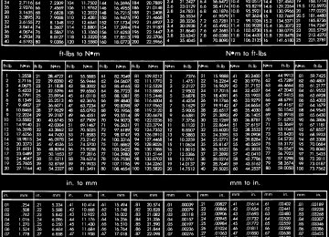
TORQUE SPECIFICATIONS
N·m 23
28
50
30
30
23
95Ft. Lbs.
In. Lbs.
17
21
37
22.5
22.5
17
70(4) Insert clutch alignment tool through clutch disc and into pilot bushing, to hold disc in place while removing bolts.
(5) Loosen pressure plate bolts evenly, a few threads at a time and in a diagonal pattern to pre- vent warping the plate.
(6) Remove bolts completely and remove pressure
plate, disc and alignment tool.
INSTALLATION
(1) Check runout and free operation of new clutch disc. (2) Lubricate crankshaft pilot bearing with a NLGI
- 2 rated grease.
(3) Install clutch alignment tool in clutch disc hub with the raised side of hub is facing away from the flywheel.
NOTE: Flywheel side is imprinted on the disc face.
(4) Install alignment tool in pilot bearing and posi-
tion disc on the flywheel.
(5) Position pressure plate over disc and onto the
flywheel (Fig. 4).
(6) Align and hold pressure plate in position and
install bolts finger tight.
(7) Tighten bolts evenly and a few threads at a
time in a diagonal pattern.
Fig.3PRESSUREPLATEPOSITION-TYPICAL
1 - FLYWHEEL 2 - ALIGNMENT MARKS 3 - PRESSURE PLATE
CAUTION: Bolts must be tightened evenly and to specified torque to avoid warping pressure plate cover.
(8) Tighten pressure plate bolts to: † V6 & V8 Engines - 50 N·m (37 ft. lbs.) † V10 & Diesel Engines - 30 N·m (22.5 ft. lbs.) (9) Remove release lever and release bearing from clutch housing. Apply Mopar high temperature bearing grease to bore of release bearing, release lever contact surfaces and release lever pivot stud (Fig. 5).
DR CLUTCH DISC (Continued)
CLUTCH
6 - 7
(10) Apply light coat of Mopar high temperature bearing grease to splines of transmission input shaft and to release bearing slide surface of the transmis- sion front bearing retainer (Fig. 6).
CAUTION: Do not over lubricate shaft splines. This can result in grease contamination of the disc.
Fig.4CLUTCHDISCANDPRESSUREPLATE
1 - FLYWHEEL 2 - PRESSURE PLATE AND DISC 3 - ALIGNMENT TOOL
Fig.6INPUTSHAFTLUBRICATIONPOINTS
1 - INPUT SHAFT 2 - BEARING RETAINER 3 - SPLINE AND RELEASE BEARING SURFACE
(11) Wipe pilot bearing surface clean. (12) Install release lever and bearing in clutch housing. Verify spring clips that retain fork on pivot ball and release bearing on fork are installed prop- erly (Fig. 7).
If release lever is installed correctly,
NOTE: the lever part number will be toward the bottom of the transmission and right side up. There is also a stamped “I” in the lever which goes to the pivot ball side of the transmission.
(13) Install
equipped.
transmission and transfer
case if
Fig.5LUBRICATIONPOINTS
1 - CLUTCH HOUSING 2 - FORK PIVOT BALL 3 - RELEASE FORK 4 - RELEASE BEARING BORE 5 - LUBE POINTS
CLUTCH
6 - 8
CLUTCH DISC (Continued)DR
(3) Replace one of
the flywheel bolts with an appropriate size threaded rod that is 10 in. (25.4 cm) long (Fig. 8). The rod will be used to mount the dial indicator.
Fig.7FORK,BEARINGANDSPRINGCLIPS
1 - FORK 2 - SPRING CLIP 3 - BEARING 4 - SPRING CLIP
(14) Check fluid level in clutch master cylinder.
CLUTCH HOUSING DIAGNOSIS AND TESTING
The clutch housing maintains alignment between the crankshaft and transmission input shaft. Mis- alignment can cause clutch noise, hard shifting, incomplete release and chatter. Also premature pilot bearing, cover release fingers and clutch disc wear. In severe cases, it can cause premature wear of the transmission input shaft and front bearing.
NOTE: Only the NV4500 clutch housing can be checked using the following bore and face runout procedures. The NV5600 clutch housing is a inte- gral part of the transmission and can only be checked off the vehicle.
CLUTCH HOUSING BORE RUNOUT
CAUTION: On diesel engines if housing bore runout exceeds 0.015 inch, the clutch housing/transmis- sion adapter plate must be replaced. On gas engines if housing bore runout exceeds 0.053 in. the clutch housing must be replaced.
NOTE: Offset dowels are available for gas engines to correct housing bore runout. They are not avail- able for diesel engines.
(1) Remove the clutch housing. (2) Remove the clutch cover and disc.
Fig.8DIALINDICATORMOUNTINGSTUD
1 - 7/16 - 20 THREAD 2 - NUT 3 - STUD OR THREADED ROD 4 - 10 INCHES LONG
(4) Remove release fork from the clutch housing. (5) Install clutch housing. Tighten the housing
bolts nearest the alignment dowels first.
(6) Mount dial indicator on the threaded rod and position indicator plunger on the clutch housing bore (Fig. 9).
Fig.9CLUTCHHOUSINGBORERUNOUT
1 - MOUNTING STUD OR ROD 2 - DIAL INDICATOR 3 - INDICATOR PLUNGER 4 - CLUTCH HOUSING BORE
(7) Rotate crankshaft until indicator plunger is at the topof the housing bore. Zero the indicator at this point.
(8) Rotate crankshaft and record indicator read- ings at eight points (45° apart) around the bore (Fig. 10). Take measurement at least twice for accuracy.
DR CLUTCH HOUSING (Continued)
CLUTCH
6 - 9
driver. Then install the housing and mount the dial indicator and check bore runout again. Rotate the dowels until the TIR is less than 0.010 inch.
Clutch Housing Face Runout
(1) Position dial indicator towards the housing face (Fig. 12) with indicator plunger on the rim of the housing bore.
Fig.10MEASUREMENTPOINTSANDREADINGS 1 - CLUTCH HOUSING BORE CIRCLE
(9) Subtract each reading from the one 180° oppo- site to determine runout and direction. Bore runout example (Fig. 10):
† 0.000 – (–0.007) = 0.007 in. † +0.002 – (–0.010) = 0.012 in. † +0.004 – (–0.005) = 0.009 in. † –0.001 – (+0.001) = –0.002 in. In this example the largest or total indicator read- ing (TIR) difference is 0.012 inch. This means the housing bore is offset from the crankshaft centerline by 0.006 in. which is 1/2 of 0.012 inch. The dowels needed to correct this have an offset of 0.007 in. (Fig. 11).
Fig.12DIALINDICATORLOCATION
1 - INDICATOR PLUNGER 2 - DIAL INDICATOR 3 - CLUTCH HOUSING FACE 4 - INDICATOR MOUNTING STUD OR ROD
(2) Rotate crankshaft until indicator plunger is at
the 10 O’clock position and zero the dial indicator.
(3) Measure and record face runout readings at four points 90° apart (Fig. 13). Take measurement at least twice for accuracy.
Fig.11ALIGNMENTDOWELSELECTION
1 - SLOT DIRECTION OF OFFSET
2 - OFFSET DOWEL
TIR VALUE
0.011 - 0.021 inch 0.022 - 0.035 inch 0.036 - 0.052 inch
OFFSET DOWEL REQUIRED
0.007 inch 0.014 inch 0.021 inch
Remove housing and install dowels with the slotted side facing out so they can be turned with a screw-
Fig.13MEASUREMENTPOINTSANDREADINGS 1 - CLUTCH HOUSING FACE CIRCLE (AT RIM OF BORE)
(4) Subtract lowest reading from highest to deter- mine total runout. If low reading was minus 0.004
in. and highest reading was plus 0.009 in. the total runout is 0.013 inch.DR
Fig.15TRANSMISSION/CLUTCHHOUSING-NV4500
1 - CLUTCH HOUSING 2 - TRANSMISSION† “C” bolts for 8.0L applications - 74.5 N·m (55
ft.lb.).
CLUTCH
6 - 10
CLUTCH HOUSING (Continued)NOTE: Maximum acceptable face runout is 0.010 inch.
To correct this example (Fig. 13) the shims needed between the clutch housing and transmission are: † 0.009 in. at the 0.000 corner † 0.012 in. at the –0.003 corner † 0.013 in. at the –0.004 corner After installing the clutch assembly and housing, tighten the housing bolts nearest the alignment dow- els first.
NOTE: Shims can be made from shim stock or sim- ilar materials of the required thickness (Fig. 14).
Fig.14ALIGNMENTSHIMS
1 - CUT/DRILL BOLT HOLE TO SIZE 2 - SHIM STOCK 3 - MAKE SHIM 1-INCH DIAMETER
REMOVAL
(1) Remove transmission and transfer case (Fig. 15). (2) Remove the starter from the clutch housing. (3) Remove clutch housing bolts and remove hous-
ing from the engine.
INSTALLATION
(1) Clean housing mounting surface of engine
block with wax and grease remover.
(2) Verify that clutch housing alignment dowels
are in good condition and properly seated.
(3) Transfer slave cylinder, release fork and boot, fork pivot stud and wire/hose brackets to new hous- ing.
(4) Align and install clutch housing on transmis- sion (Fig. 16). Tighten housing bolts closest to align- ment dowels first and to the following torque values: † 1/4in. diameter “A” bolts - 4.5 N·m (40 in.lb.). † 3/8in. diameter “A” bolts - 47.5 N·m (35 ft.lb.). † 7/16in. diameter “A” bolts - 68 N·m (50 ft.lb.). † “B” bolts for 5.9L TD/8.0L applications - 47.5
N·m (35 ft.lb.). † “C” bolts for 5.9L TD applications - 47.5 N·m (35ft.lb.).
Fig.16CLUTCHHOUSINGINSTALLATION-NV4500
1 - ENGINE BLOCK 2 - CLUTCH DISC AND COVER 3 - CLUTCH HOUSING 4 - DUST COVER(5) Install the starter to the clutch housing.
DR CLUTCH HOUSING (Continued)
CLUTCH
6 - 11
(6) Install the clutch housing dust shield to the
(7) Install
transmission and transfer
case,
if
clutch housing.
equipped.
CLUTCH RELEASE BEARING REMOVAL
(1) Remove transmission and transfer case,
if
equipped.
(2) Remove spring clip. (3) Disconnect release bearing from release fork
and remove bearing (Fig. 17).
Fig.18ClutchReleaseForkAnd
1 - PIVOT BALL 2 - FORK 3 - SLAVE CYLINDER OPENING 4 - BEARING
(6) Install transmission and transfer case. (7) Check clutch master cylinder fluid level.
FLYWHEEL DIAGNOSIS AND TESTING
Check flywheel runout whenever misalignment is suspected. Flywheel runout should not exceed 0.08
mm (0.003 in.). Measure runout at the outer edge of the flywheel face with a dial indicator. Mount the indicator on a stud installed in place of one of the fly- wheel bolts.Common causes of runout are: † heat warpage † improper machining † incorrect bolt tightening † improper seating on crankshaft flange shoulder † foreign material on crankshaft flange Flywheel machining is not recommended. The fly- wheel clutch surface is machined to a unique contour and machining will negate this feature. Minor fly- wheel scoring can be cleaned up by hand with 180
grit emery or with surface grinding equipment. Remove only enough material to reduce scoring (approximately 0.001 - 0.003 in.). Heavy stock removal is not recommended. Replace the flywheel if scoring is severe and deeper than 0.076 mm (0.003
in.). Excessive stock removal can result in flywheel cracking or warpage after installation; it can also weaken the flywheel and interfere with proper clutch release.Clean the crankshaft flange before mounting the flywheel. Dirt and grease on the flange surface may cock the flywheel causing excessive runout. Use new
Fig.17CLUTCHRELEASECOMPONENTS
1 - CONED WASHER 2 - CLUTCH HOUSING 3 - RELEASE FORK 4 - RELEASE BEARING AND SLEEVE 5 - PIVOT 23 N·m (200 IN. LBS.) 6 - SPRING CLIP
INSTALLATION
(1) Inspect bearing slide surface on transmission front bearing retainer. Replace retainer if slide sur- face is scored, worn, or cracked.
(2) Inspect release lever and pivot stud. Be sure stud is secure and in good condition. Be sure fork is not distorted or worn. Replace fork spring clips if bent or damaged.
(3) Lubricate input shaft splines, bearing retainer slide surface, lever pivot ball stud, and release lever pivot surface with Mopart high temperature bearing grease.
(4) Install release fork and release bearing (Fig. 18). Be sure fork and bearing are properly secured by spring clips. Also be sure that the release fork is installed properly. The rear side of the release lever has one end with a raised area. This raised area goes toward the slave cylinder side of the transmission.
(5) Install clutch housing, if removed.
DR
WARNING: WEAR PROTECTIVE GOGGLES OR SAFETY GLASSES AND HEAT RESISTENT GLOVES WHEN HANDLING A HEATED RING GEAR.
(1) The heated gear must be installed evenly to
avoid misalignment or distortion.
(2) Position and install the heated ring gear on the flywheel with a shop press and a suitable press plates.
(3) Place flywheel on work bench and let it cool in normal shop air. Allow the ring gear to cool down completely before installation it on the engine.
CAUTION: Do not use water or compressed air to cool the flywheel. The rapid cooling produced by water or compressed air will distort or crack the new gear.
INSTALLATION
(1) Install flywheel on the crank shaft. (2) Install flywheel bolts and tighten to 95 N·m (70
ft. lbs.).
(3) Install clutch. (4) Install transmission.
PILOT BEARING REMOVAL
(1) Remove transmission. (2) Remove clutch disc. (3) Use a suitable blind hole puller to remove pilot
bearing.
INSTALLATION
(1) Clean bearing bore with solvent and wipe dry
with shop towel.
(2) Install new bearing with clutch alignment tool (Fig. 19). Drive bearing into place with the letter side of the bearing facing the transmission. Bearing should be flush with edge of bearing bore.
CAUTION: Do not allow bearing to become cocked and do not recess bearing.
CLUTCH
6 - 12
FLYWHEEL (Continued)bolts when remounting a flywheel and secure the bolts with Mopar Lock And Seal or equivalent. Tighten flywheel bolts to specified torque only. Over- tightening can distort the flywheel hub causing runout.
REMOVAL
(1) Remove transmission. (2) Remove pressure plate and clutch. (3) Remove flywheel bolts and remove flywheel.
DISASSEMBLY
NOTE: If the teeth are worn or damaged, the fly- wheel should be replaced as an assembly. This is the recommended repair. In cases where a new fly- wheel is not readily available, (V10/Diesel Engine only) a replacement ring gear can be installed. The following procedure must be observed to avoid damaging the flywheel and replacement gear.
WARNING: WEAR PROTECTIVE GOGGLES OR SAFETY GLASSES WHILE CUTTING RING GEAR.
(1) Mark position of the old gear for alignment ref- erence on the flywheel. Use a scriber for this pur- pose.
(2) Remove the old gear by cutting most of the way through it (at one point) with an abrasive cut-off wheel. Then complete removal with a cold chisel or punch.
ASSEMBLY
NOTE: The ring gear is a shrink fit on the flywheel. This means the gear must be expanded by heating in order to install it. The method of heating and expanding the gear is extremely important. Every surface of the gear must be heated at the same time to produce uniform expansion. An oven or similar enclosed heating device must be used. Tem- perature required for uniform expansion is approxi- mately 375° F.
CAUTION: Do not use an oxy/acetylene torch to remove the old gear, or to heat and expand a new gear. The high temperature of the torch flame can cause localized heating that will damage the fly- wheel. In addition, using the torch to heat a replace- ment and expansion. The torch flame can also anneal the gear teeth resulting in rapid wear and damage after installation.
gear will
heating
uneven
cause
DR PILOT BEARING (Continued)
CLUTCH
6 - 13
Fig.19PILOTBEARING
1 - PILOT BEARING 2 - ALIGNMENT TOOL 3 - LETTER SIDE MUST FACE TRANSMISSION
(3) Install clutch disc, pressure plate and trans-
mission.
LINKAGE REMOVAL
CAUTION: The hydraulic linkage has a quick dis- connect at the slave cylinder. This fitting should never be disconnected or tampered with. Once the hydraulic line is connected to the slave cylinder, it should never be disconnected.
(1) Raise and support vehicle. (2) Remove nuts attaching slave cylinder to studs
on clutch housing (Fig. 20).
(3) Remove slave cylinder from clutch housing. (4) Remove plastic clip securing the hydraulic line to the dash panel from the lower dash panel flange. (5) Remove plastic clip securing hydraulic line to
the dash panel from the upper dash panel stud.
(6) Lower vehicle. (7) Disconnect clutch pedal interlock switch wires
(Fig. 21).
(8) Remove clutch master cylinder rod pin. (9) Verify that cap on clutch master cylinder reser- voir is tight. This will avoid spillage during removal. (10) Remove clutch master cylinder nuts holding
the to the dash panel.
Fig.20SLAVECYLINDER
1 - MOUNTING NUTS 2 - SLAVE CYLINDER
Fig.21CLUTCHMASTERCYLINDER
1 - MASTER CYLINDER 2 - INTERLOCK CONNECTOR 3 - ROD PIN
(11) Remove clutch cylinders, reservoir and con-
necting lines from vehicle.
INSTALLATION
(1) Position cylinders and connecting line in vehi- cle engine compartment. Position clutch hydraulic line against the dash panel and behind all engine hoses and wiring.
(2) Apply a light coating of grease to the inside
diameter of the master cylinder push rod eye.
(3) Install clutch master cylinder on dash panel and tighten clutch master cylinder nuts to 28 N·m (21 ft. lbs.).
(4) Install clutch master cylinder push rod pin. (5) Connect clutch pedal position interlock switch
wires.
CLUTCH
6 - 14
LINKAGE (Continued)(6) Install plastic clip securing hydraulic line to
the dash panel into the lower dash panel flange.
(7) Install plastic clip securing hydraulic line to
the dash panel onto the upper dash panel stud.
(8) Raise vehicle. (9) Install slave cylinder and verify cylinder rod is
properly seated in release lever.
(10) Install and tighten slave cylinder nuts to 23
N·m (17 ft. lbs.).
(11) If new clutch linkage is being installed, con- nect the clutch hydraulic line to the clutch slave cyl- inder.
CAUTION: Once the clutch hydraulic line is con- nected to the slave cylinder, it should never be dis- connected.
(12) Lower vehicle. (13) Operate linkage several times to verify proper
operation.
CLUTCH PEDAL POSITION SWITCH DESCRIPTION
A clutch pedal position (interlock)
switch is mounted on the clutch master cylinder push rod (Fig. 22). The switch is actuated by clutch pedal move- ment.
DR
OPERATION
The clutch pedal position switch is used to prevent starter motor engagement unless the clutch pedal is depressed.
An input from this switch is also used to either shut down and/or prevent operation of the speed con- trol system when the clutch pedal is depressed.
The position switch is an integral part of the clutch master cylinder push rod and is not serviced sepa- rately.
DIAGNOSIS AND TESTING
(1) Locate clutch switch 2-wire electrical connector. This will be the test point. This connector is attached to pedal support bracket located under instrument panel to left of clutch pedal (Fig. 23). Disconnect wir- ing at this point.
(2) Check for switch continuity with an ohmmeter while operating clutch pedal up and down. Continu- ity should be broken and reapplied each time pedal is pressed.
(3) If continuity is not present, or is always present at any pedal position, replace switch. Switch is not serviced separately. Replace clutch master cylinder.
Fig.22LOCATION,CLUTCHPEDALPOSITION
SWITCH
1 - CLUTCH MASTER CYLINDER 2 - CLUTCH PEDAL POSITION SWITCH
Fig.23CLUTCHSWITCHTESTPOINT
1 - PEDAL SUPPORT BRACKET 2 - ELECTRICAL CONNECTOR
DR
COOLING
7 - 1
COOLING
TABLE OF CONTENTS
page
page
COOLING
DESCRIPTION
DESCRIPTION - COOLING SYSTEM FLOW
3.7L/4.7L ENGINE . . . . . . . . . . . . . . . . . . . . . . 1
DESCRIPTION - COOLING SYSTEM FLOW -
5.9L ENGINE . . . . . . . . . . . . . . . . . . . . . . . . . . 1
DESCRIPTION—COOLING SYSTEM FLOW -
5.9L DIESEL . . . . . . . . . . . . . . . . . . . . . . . . . . 2
DESCRIPTION - HOSE CLAMPS . . . . . . . . . . . 3OPERATION
OPERATION—COOLING SYSTEM . . . . . . . . . 3
OPERATION—HOSE CLAMPS . . . . . . . . . . . . 5DIAGNOSIS AND TESTING
DIAGNOSIS AND TESTING—ON-BOARD
STANDARD PROCEDURE - COOLING
SYSTEM CLEANING/REVERSE FLUSHING . . 17
STANDARD PROCEDURE—DRAINING
COOLING SYSTEM 3.7L/4.7L/5.7L ENGINE . . 18
STANDARD PROCEDURE - REFILLING
COOLING SYSTEM 3.7L/4.7L/5.7L ENGINE . . 18
STANDARD PROCEDURE—DRAINING
COOLING SYSTEM 5.9L/8.0L ENGINE . . . . . . 18
STANDARD PROCEDURE—REFILLING
COOLING SYSTEM 5.9L/8.0L ENGINE . . . . . . 18
STANDARD PROCEDURE—DRAINING
COOLING SYSTEM 5.9L DIESEL ENGINE . . . 19
STANDARD PROCEDURE—REFILLING
COOLING SYSTEM 5.9L DIESEL ENGINE . . . 19
DIAGNOSTICS (OBD) . . . . . . . . . . . . . . . . . . . 5
STANDARD PROCEDURE - ADDING
DIAGNOSIS AND TESTING—COOLING
ADDITIONAL COOLANT. . . . . . . . . . . . . . . . . 19
SYSTEM - TESTING FOR LEAKS . . . . . . . . . . 5
SPECIFICATIONS
DIAGNOSIS AND TESTING - COOLING
SYSTEM DIESEL ENGINE . . . . . . . . . . . . . . . . 7
DIAGNOSIS AND TESTING - PRELIMINARY
CHECKS . . . . . . . . . . . . . . . . . . . . . . . . . . . . 10
STANDARD PROCEDURE
STANDARD PROCEDURE - COOLANT
LEVEL CHECK . . . . . . . . . . . . . . . . . . . . . . . . 17
TORQUE . . . . . . . . . . . . . . . . . . . . . . . . . . . . 20
SPECIFICATIONS - . . . . . . . . . . . . . . . . . . . . 20SPECIAL TOOLS
COOLING . . . . . . . . . . . . . . . . . . . . . . . . . . . 20
ACCESSORY DRIVE . . . . . . . . . . . . . . . . . . . . . . 22
ENGINE . . . . . . . . . . . . . . . . . . . . . . . . . . . . . . . 35
TRANSMISSION . . . . . . . . . . . . . . . . . . . . . . . . . 72COOLING
DESCRIPTION
DESCRIPTION - COOLING SYSTEM FLOW 3.7L/4.7L ENGINE
The cooling system regulates engine operating tem- perature. It allows the engine to reach normal oper- ating temperature as quickly as possible. It also maintains normal operating temperature and pre- vents overheating.
The cooling system provides a means of heating the passenger compartment and cooling the auto- matic transmission fluid (if equipped). The cooling system is pressurized and uses a centrifugal water pump to circulate coolant through the system and a coolant deaeration and reserve system that utilizes a pressurized degas bottle (hot bottle).
An optional factory installed maximum duty cool- ing package is available on most models. This pack- age will provide additional cooling capacity for
vehicles used under extreme conditions such as trailer towing in high ambient temperatures (Fig. 1).
DESCRIPTION - COOLING SYSTEM FLOW - 5.9L ENGINE
The cooling system regulates engine operating tem- perature. It allows the engine to reach normal oper- ating temperature as quickly as possible. It also maintains normal operating temperature and pre- vents overheating.
The cooling system also provides a means of heat- ing the passenger compartment and cooling the auto- matic transmission fluid (if equipped). The cooling system uses a coolant recovery / reserve system that utilizes an ambient overflow bottle.
An optional factory installed maximum duty cool- ing package is available on most models. This pack- age will provide additional cooling capacity for vehicles used under extreme conditions such as trailer towing in high ambient temperatures (Fig. 2).
COOLING
7 - 2
COOLING (Continued)DR
1 - LH CYL. HEAD 2 - BLEED 3 - THERMOSTAT LOCATION 4 - RH CYL. HEAD 5 - RH BANK CYL. BLOCK
Fig.1EngineCoolingSystemFlow-3.7L/4.7L 6 - LH BANK CYL. BLOCK 7 - COOLANT TEMP. SENSOR 8 - FROM HEATER CORE 9 - TO HEATER CORE
DESCRIPTION—COOLING SYSTEM FLOW - 5.9L DIESEL
The diesel engine cooling system consists of : † Cross-flow radiator † Belt driven water pump † Belt driven mechanical cooling fan † Electronic viscous fan drive † Fan shroud † Radiator pressure cap
† Vertically mounted thermostat † Coolant reserve/recovery system † Transmission oil cooler † Coolant Coolant flow circuits for the 5.9L diesel engine are
shown in (Fig. 3).
DR COOLING (Continued)
COOLING
7 - 3
1 - HEATER 2 - BYPASS*
Fig.2ENGINECOOLINGSYSTEMFLOW-5.9L 3 - CROSSFLOW RADIATOR 4 - THERMOSTAT LOCATION
DESCRIPTION - HOSE CLAMPS
The cooling system utilizes
spring type hose clamps. If a spring type clamp replacement is neces- sary, replace with the original Mopart equipment spring type clamp.
CAUTION: A number or letter is stamped into the tongue of constant tension clamps. If replacement is necessary, use only a original equipment clamp with matching number or letter and ensure the clamp has the same size width (Fig. 4).
OPERATION
OPERATION—COOLING SYSTEM
The cooling system regulates engine operating tem- perature. It allows the engine to reach normal oper- ating temperature as quickly as possible. It also maintains normal operating temperature and pre- vents overheating.
The cooling system also provides a means of heat- ing the passenger compartment and cooling the auto- matic transmission fluid (if equipped). The cooling
COOLING
7 - 4
COOLING (Continued)DR
Fig.3CoolingSystemCirculation—DieselEngine
DR COOLING (Continued)
COOLING
7 - 5
† If an open or shorted condition has developed in the electronically controlled viscous fan clutch circuit, a Diagnostic Trouble Code (DTC) can be set. † If fan speed is not detected a DTC will be set. † Coolant temperature sensor circuit problems can
set a DTC.
If the problem is sensed in a monitored circuit often enough to indicated an actual problem, a DTC is stored. The DTC will be stored in the ECM mem- ory for eventual display to the service technician. (Refer to 25 - EMISSIONS CONTROL - DESCRIP- TION).
Fig.4SpringClampSizeLocation
1 - SPRING CLAMP SIZE LOCATION
system is pressurized and uses a centrifugal water pump to circulate coolant throughout the system.
5.9L, 5.9L Diesel, and 8.0L engines utilize an ambient overflow bottle for coolant recovery/reserve. The 3.7L and 4.7L engines utilize a pressurized degas bottle for coolant deaeration and reserve. This degas bottle has coolant flowing through it continu- ously, supplied by a vent in the hot side radiator tank and returning to the heater return hose.
An optional factory installed maximum duty cool- ing package is available on most models. This pack- age will provide additional cooling capacity for vehicles used under extreme conditions such as trailer towing in high ambient temperatures.
OPERATION—HOSE CLAMPS
The spring type hose clamp applies constant ten- sion on a hose connection. To remove a spring type hose clamp, only use constant tension clamp pliers designed to compress the hose clamp.
DIAGNOSIS AND TESTING
DIAGNOSIS AND TESTING—ON-BOARD DIAGNOSTICS (OBD)
COOLING SYSTEM RELATED DIAGNOSTICS
The Engine Control Module (ECM) has been pro- grammed to monitor certain cooling system compo- nents:† If the engine has remained cool for too long a period, such as with a stuck open thermostat, a Diag- nostic Trouble Code (DTC) can be set.
ACCESSING DIAGNOSTIC TROUBLE CODES
To read DTC’s and to obtain cooling system data, (Refer to 25 - EMISSIONS CONTROL - DESCRIP- TION).
ERASING TROUBLE CODES
After the problem has been repaired, use the DRBIIIt scan tool to erase a DTC. Refer to the appropriate Powertrain Diagnostic Procedures ser- vice information for operation of the DRBIIIt scan tool.
DIAGNOSIS AND TESTING—COOLING SYSTEM - TESTING FOR LEAKS
ULTRAVIOLET LIGHT METHOD
A leak detection additive is available through the parts department that can be added to cooling sys- tem. The additive is highly visible under ultraviolet light (black light). Pour one ounce of additive into cooling system. Place heater control unit in HEAT position. Start and operate the engine until the radi- ator upper hose is warm to the touch. Aim the com- mercially available black light tool at the components to be checked. If leaks are present, the black light will cause the additive to glow a bright green color. The black light can be used in conjunction with a pressure tester to determine if any external leaks exist (Fig. 5).
PRESSURE TESTER METHOD
The engine should be at normal operating temper- ature. Recheck the system cold if the cause of coolant loss is not located during the warm engine examina- tion.
WARNING: HOT, PRESSURIZED COOLANT CAN CAUSE INJURY BY SCALDING.
Carefully remove the radiator pressure cap from the filler neck and check the coolant level. Push down on the cap to disengage it from the stop tabs. Wipe the inside of the filler neck and examine the
COOLING
7 - 6
COOLING (Continued)Fig.5LeakDetectionUsingBlackLight—Typical 1 - TYPICAL BLACK LIGHT TOOL
DR
Drops Quickly: Indicates that serious leakage is occurring. Examine the system for external leakage. If leaks are not visible, inspect for internal leakage. Large radiator leak holes should be repaired by a reputable radiator repair shop.
INTERNAL LEAKAGE INSPECTION
Remove the engine oil pan drain plug and drain a small amount of engine oil. If coolant is present in the pan, it will drain first because it is heavier than oil. An alternative method is to operate engine for a short period to churn the oil. After this is done, remove the engine dipstick and inspect for water globules. Also inspect the transmission dipstick for water globules and transmission fluid cooler for leak- age.
WARNING: WITH RADIATOR PRESSURE TESTER TOOL INSTALLED ON RADIATOR, DO NOT ALLOW PRESSURE TO EXCEED 145 kPa (21 PSI). PRES- SURE WILL BUILD UP QUICKLY IF A COMBUSTION LEAK IS PRESENT. TO RELEASE PRESSURE, ROCK TESTER FROM SIDE TO SIDE. WHEN REMOVING TESTER, DO NOT TURN TESTER MORE THAN 1/2 TURN IF SYSTEM IS UNDER PRESSURE.
lower inside sealing seat for nicks, cracks, paint, dirt and solder residue. Inspect the radiator-to- reserve/ overflow tank hose for internal obstructions. Insert a wire through the hose to be sure it is not obstructed. Inspect the cams on the outside of the filler neck. If the cams are damaged, seating of the pressure cap valve and tester seal will be affected.
Attach pressure tester (7700 or an equivalent) to
radiator filler neck.
Operate the tester pump to apply 103.4 kPa (15
psi) pressure to the system. If the hoses enlarge excessively or bulges while testing, replace as neces- sary. Observe the gauge pointer and determine the condition of the cooling system according to following criteria:Holds Steady: If the pointer remains steady for two minutes, serious coolant leaks are not present in system. However, there could be an internal leak that does not appear with normal system test pres- sure. If it is certain that coolant is being lost and leaks cannot be detected, inspect for interior leakage or perform Internal Leakage Test. Refer to INTER- NAL LEAKAGE INSPECTION.
Drops Slowly: Indicates a small leak or seepage is occurring. Examine all of the connections for seep- age or slight leakage with a flashlight. Inspect the radiator, hoses, gasket edges and heater. Seal the small leak holes with a Sealer Lubricant (or equiva- lent). Repair the leak holes and inspect the system again with pressure applied.
Operate the engine without the pressure cap on the radiator until the thermostat opens. Attach a Pressure Tester to the filler neck. If pressure builds up quickly it indicates a combustion leak exists. This is usually the result of a cylinder head gasket leak or crack in engine. Repair as necessary.
If there is not an immediate pressure increase, pump the Pressure Tester. Do this until indicated pressure is within system range of 110 kPa (16 psi). Fluctuation of the gauge pointer indicates compres- sion or combustion leakage into cooling system.
Because the vehicle is equipped with a catalytic converter, do not short out cylinders to isolate com- pression leak.
If the needle on dial of the pressure tester does not fluctuate, race engine a few times to check for an abnormal amount of coolant or steam. This would be emitting from exhaust pipe. Coolant or steam from exhaust pipe may indicate a faulty cylinder head gas- ket, cracked engine cylinder block or cylinder head. A convenient check for exhaust gas leakage into cooling system is provided by a commercially avail- able Block Leak Check tool. Follow manufacturers instructions when using this product.
COMBUSTION LEAKAGE TEST—WITHOUT PRESSURE TESTER
DO NOT WASTE reusable coolant. If the solution is clean, drain the coolant into a clean container for reuse.
DR COOLING (Continued)
WARNING: DO NOT REMOVE CYLINDER BLOCK DRAIN PLUGS OR LOOSEN RADIATOR DRAIN- COCK WITH SYSTEM HOT AND UNDER PRESSURE. SERIOUS BURNS FROM COOLANT CAN OCCUR.
coolant
Drain sufficient
to allow thermostat removal. (Refer to 7 - COOLING/ENGINE/ENGINE COOLANT THERMOSTAT - REMOVAL). Remove accessory drive belt (Refer to 7 - COOLING/ACCES- SORY DRIVE/DRIVE BELTS - REMOVAL).
Add coolant to radiator to bring level to within 6.3
mm (1/4 in) of the top of the thermostat housing.
COOLING
7 - 7
CAUTION: Avoid overheating. Do not operate engine for an excessive period of time. Open drain- cock immediately after test to eliminate boil over.
Start engine and accelerate rapidly three times, to approximately 3000 rpm while observing coolant. If internal engine combustion gases are leaking into cooling system, bubbles will appear in coolant. If bub- bles do not appear, internal combustion gas leakage is not present.
DIAGNOSIS AND TESTING - COOLING SYSTEM DIESEL ENGINE
COOLING SYSTEM DIAGNOSIS—DIESEL ENGINE
CONDITION
POSSIBLE CAUSES
CORRECTION
TEMPERATURE GAUGE READS LOWNOTE: Information on dash cluster is displayed based on broadcast data from ECM. DTC will be set for engine sensor circuit concern.
1. Vehicle is equipped with a heavy duty cooling system. 2. Thermostat stuck open 3. Coolant level low.
4. Temperature gauge not functioning correctly.
1. None. System operating normally.
2. Inspect and test thermostat. 3. Fill cooling system. (Refer to 7 - COOLING - STANDARD PROCEDURE) 4. Check cluster (Refer to 8 - ELECTRICAL/INSTRUMENT CLUSTER - DIAGNOSIS AND TESTING)
COOLING
7 - 8
COOLING (Continued)DR
CONDITION
POSSIBLE CAUSES
CORRECTION
TEMPERATURE GAUGE READS HIGH. COOLANT MAY OR MAY NOT BE LEAKING FROM SYSTEMNOTE: Information on dash cluster is displayed based on broadcast data from ECM. DTC will be set for engine sensor circuit concern.
1. Vehicle overloaded, high ambient (outside) temperatures with A/C turned on, stop and go driving or prolonged operation at idle speeds. 2. Temperature gauge not functioning correctly.
3. Air trapped in cooling system
4. Radiator cap faulty. 5. Plugged A/C or radiator cooling fins. 6. Coolant mixture incorrect.
7. Thermostat stuck shut.
8. Bug screen or winter front being used. 9. Electronically controlled viscous fan drive not operating properly.
10. Cylinder head gasket leaking.
11. Heater core leaking. 12. Cooling system hoses leaking.
13. Brakes dragging.
14. Accessory drive belt. 15. Water Pump.
1. Temporary condition, repair not required. Notify customer of vehicle operation instructions located in Owners Manual. 2. Check cluster (Refer to 8 - ELECTRICAL/INSTRUMENT CLUSTER - DIAGNOSIS AND TESTING) 3. Drain cooling system (Refer to 7 - COOLING - STANDARD PROCEDURE) and refill (Refer to 7
- COOLING - STANDARD PROCEDURE) 4. Replace radiator cap. 5. Clean all debris away from A/C and radiator cooling fins. 6. Drain cooling system (Refer to 7 - COOLING - STANDARD PROCEDURE) refill with correct mixture (Refer to 7 - COOLING - STANDARD PROCEDURE). 7. Inspect and test thermostat. Replace thermostat if necessary. 8. Remove bug screen or winter front. 9. Check viscous fan (Refer to 7 - COOLING/ENGINE/FAN DRIVE VISCOUS CLUTCH - DIAGNOSIS AND TESTING) 10. Check for leaking head gaskets (Refer to 7 - COOLING - DIAGNOSIS AND TESTING). 11. Replace heater core. 12. Tighten clamps or Replace hoses. 13. Check brakes. (Refer to 5 - BRAKES/HYDRAULIC/ MECHANICAL - DIAGNOSIS AND TESTING) 14. Inspect. Replace as necessary. 15. Inspect and replace as necessary.DR COOLING (Continued)
COOLING
7 - 9
CONDITION
POSSIBLE CAUSES
CORRECTION
TEMPERATURE GAUGE READING INCONSISTENT (ERRATIC, CYCLES OR FLUCTUATES)NOTE: Information on dash cluster is displayed based on broadcast data from ECM. DTC will be set for engine sensor circuit concern.
1. Heavy duty cooling system, extreme cold ambient (outside) temperature or heater blower motor in high position.
2. Temperature gauge or sensor defective.
3. Temporary heavy usage or load. 4. Air trapped in cooling system.
5. Water pump 6. Air leak on suction side of water pump.
1. None. System operating normally.
2. Check cluster or engine coolant temp sensor (Refer to 8 - ELECTRICAL/INSTRUMENT CLUSTER - DIAGNOSIS AND TESTING) 3. None. Normal condition. 4. Fill cooling system (Refer to 7 - COOLING - STANDARD PROCEDURE). 5. Replace water pump. 6. Check for leak. (Refer to 7 - COOLING - DIAGNOSIS AND TESTING)
RADIATOR CAP LEAKING STEAM AND /OR COOLANT INTO RESERVOIR BOTTLE. (TEMPERATURE GAUGE MAY READ HIGH)
HOSE OR HOSES COLLAPSE WHEN ENGINE IS COOLING.
NOISY FAN
1. Radiator cap defective.
1. Replace radiator cap.
2. Radiator neck surface damaged.
2. Replace radiator.
1. Vacuum created in cooling system on engine cool-down is not being relieved through coolant reservoir/overflow system.
1. Replace radiator cap, check vent hose between radiator and reservoir bottle for blockage also check reservoir bottle vent for blockage.
1. Fan blade(s) loose, damaged. 2. Electronically controlled viscous fan drive. 3. Fan blades striking surrounding objects. 4. Electronically controlled viscous fan drive bearing.
5. Electronically controlled viscous fan stuck on
6. Obstructed air flow through radiator.
1. Replace fan blade assembly. 2. None. Normal condition.
3. Locate contact point and repair as necessary. 4. Check viscous fan (Refer to 7 - COOLING/ENGINE/FAN DRIVE VISCOUS CLUTCH - DIAGNOSIS AND TESTING) 5. Check viscous fan (Refer to 7 - COOLING/ENGINE/FAN DRIVE VISCOUS CLUTCH - DIAGNOSIS AND TESTING) 6. Remove obstruction.
COOLING
7 - 10
COOLING (Continued)DR
CONDITION
POSSIBLE CAUSES
CORRECTION
INADEQUATE AIR CONDITIONER PERFORMANCE (COOLING SYSTEM SUSPECTED)
1. Radiator and/or A/C condenser air flow obstructed.
2. Electronically controlled viscous fan drive not working.
3. Air seals around radiator damaged or missing.
INADEQUATE HEATER PERFORMANCE. GAUGE MAY OR MAY NOT READ LOW.
1. Heavy duty cooling system, and cooler ambient temperatures.
2. Obstruction in heater hoses.
HEAT ODOR
3. Electronically controlled viscous fan stuck on
4. Water pump damaged.
1. Damaged or missing drive line heat shields. 2. Electronically controlled viscous fan drive damaged.
1. Remove obstruction and/or clean.
2. Check fan drive. (Refer to 7 - COOLING/ENGINE/FAN DRIVE VISCOUS CLUTCH - DIAGNOSIS AND TESTING) 3. Inspect air seals, repair or replace as necessary.
1. None. Normal condition.
2. Remove hoses, remove obstruction. Check fan drive. (Refer to 7 - COOLING/ENGINE/FAN DRIVE VISCOUS CLUTCH - DIAGNOSIS AND TESTING) 4. Replace water pump.
1. Repair or replace damaged or missing heat shields. 2. Check thermal viscous fan drive. (Refer to 7 - COOLING/ENGINE/ FAN DRIVE VISCOUS CLUTCH - DIAGNOSIS AND TESTING)
DIAGNOSIS AND TESTING - PRELIMINARY CHECKS
ENGINE COOLING SYSTEM OVERHEATING
Establish what driving conditions caused the com- plaint. Abnormal loads on the cooling system such as the following may be the cause: † PROLONGED IDLE † VERY HIGH AMBIENT TEMPERATURE † SLIGHT TAIL WIND AT IDLE † SLOW TRAFFIC † TRAFFIC JAMS † HIGH SPEED OR STEEP GRADES Driving techniques that avoid overheating are: † Idle with A/C off when temperature gauge is at † Increasing engine speed for more air flow is rec-
end of normal range.
ommended.
TRAILER TOWING:
Consult Trailer Towing section of owners manual.
Do not exceed limits.
RECENT SERVICE OR ACCIDENT REPAIR:
Determine if any recent service has been per- formed on vehicle that may effect the cooling system. This may be:
† Engine adjustments (incorrect timing) † Slipping engine accessory drive belt(s) † Brakes (possibly dragging) † Changed parts. Incorrect water pump or pump rotating in wrong direction due to belt not correctly routed† Reconditioned radiator or cooling system refill- ing (possibly under filled or air trapped in system). † Service to electrically controlled viscous fan
clutch
NOTE: If investigation reveals none of the previous items as a cause for an engine overheating com- plaint, to COOLING SYSTEM DIAGNOSIS CHART BELOW.
refer
These charts are to be used as a quick-reference to COOLING SYSTEM DIAGNOSIS
only. Refer CHART
DR COOLING (Continued)
COOLING
7 - 11
COOLING SYSTEM DIAGNOSIS CHART
CONDITION
POSSIBLE CAUSES
CORRECTION
TEMPERATURE GAUGE READS LOW
1. Has a Diagnostic Trouble Code (DTC) been set indicating a stuck open thermostat?
2. Is the temperature sending unit connected?
3. Is the temperature gauge operating OK?
4. Coolant level low in cold ambient temperatures accompanied with poor heater performance.
5. Improper operation of internal heater doors or heater controls.
1. (Refer to 25 - EMISSIONS CONTROL - DESCRIPTION) for On-Board Diagnostics and DTC information. Replace thermostat if necessary. 2. Check the temperature sensor connector. (Refer to 8 - ELECTRICAL/ INSTRUMENT CLUSTER - SCHEMATIC - ELECTRICAL) Repair connector if necessary. 3. Check gauge operation. (Refer to 8 - ELECTRICAL/INSTRUMENT CLUSTER/ ENGINE TEMPERATURE GAUGE - DESCRIPTION). Repair as necessary. 4. Check coolant level in the coolant reserve/overflow tank or degas bottle and the radiator. Inspect system for leaks. Repair leaks as necessary. Refer to the Coolant section of the manual text for WARNINGS and CAUTIONS associated with removing the radiator cap. 5. Inspect heater and repair as necessary. (Refer to 24 - HEATING & AIR CONDITIONING - DIAGNOSIS AND TESTING) for procedures.
COOLING
7 - 12
COOLING (Continued)DR
CONDITION
POSSIBLE CAUSES
CORRECTION
TEMPERATURE GAUGE READS HIGH OR THE COOLANT WARNING LAMP ILLUMINATES. COOLANT MAY OR MAY NOT BE LOST OR LEAKING FROM THE COOLING SYSTEM
1. Trailer is being towed, a steep hill is being climbed, vehicle is operated in slow moving traffic, or engine is being idled with very high ambient (outside) temperatures and the air conditioning is on. Higher altitudes could aggravate these conditions.
2. Is the temperature gauge reading correctly?
3. Is the temperature warning illuminating unnecessarily?
4. Coolant low in coolant reserve/overflow tank and radiator? 5. Pressure cap not installed tightly. If cap is loose, boiling point of coolant will be lowered. Also refer to the following Step 6. 6. Poor seals at the radiator cap.
7. Coolant level low in radiator but not in coolant reserve/ overflow tank. This means the radiator is not drawing coolant from the coolant reserve/ overflow tank as the engine cools (5.9L).
8. Incorrect coolant concentration
9. Coolant not flowing through system
1. This may be a temporary condition and repair is not necessary. Turn off the air conditioning and attempt to drive the vehicle without any of the previous conditions. Observe the temperature gauge. The gauge should return to the normal range. If the gauge does not return to the normal range, determine the cause for overheating and repair. Refer to Possible Causes (2-18). 2. Check gauge. (Refer to 8 - ELECTRICAL/INSTRUMENT CLUSTER - SCHEMATIC - ELECTRICAL). Repair as necessary. 3. (Refer to 8 - ELECTRICAL/ INSTRUMENT CLUSTER - SCHEMATIC - ELECTRICAL). 4. Check for coolant leaks and repair as necessary. (Refer to 7 - COOLING - DIAGNOSIS AND TESTING). 5. Tighten cap
6. (a) Check condition of cap and cap seals. Refer to Radiator Cap. Replace cap if necessary. (b) Check condition of radiator filler neck. If neck is bent or damaged, replace radiator (5.9L) or degas bottle (3.7L, 4.7L). 7. (a) Check condition of radiator cap and cap seals. Refer to Radiator Cap in this Group. Replace cap if necessary. (b) Check condition of radiator filler neck. If neck is bent or damaged, replace radiator. (c) Check condition of the hose from the radiator to the coolant tank. It should fit tight at both ends without any kinks or tears. Replace hose if necessary. (d) Check coolant reserve/overflow tank and tanks hoses for blockage. Repair as necessary. 8. Check coolant. (Refer to LUBRICATION & MAINTENANCE/FLUID TYPES - DESCRIPTION). 9. Check for coolant flow at radiator filler neck with some coolant removed, engine warm and thermostat open. Coolant should be observed flowing through radiator. If flow is not observed, determine area of obstruction and repair as necessary.
DR COOLING (Continued)
COOLING
7 - 13
CONDITION
POSSIBLE CAUSES
CORRECTION
10. Radiator or A/C condenser fins are dirty or clogged.
11. Radiator core is corroded or plugged. 12. Fuel or ignition system problems.
13. Dragging brakes.
14. Bug screen or cardboard is being , reducing airflow. 15. Thermostat partially or completely shut.
16. Viscous fan drive not operating properly.
17. Cylinder head gasket leaking.
18. Heater core leaking.
10. Remove insects and debris. (Refer to 7 - COOLING - STANDARD PROCEDURE). 11. Have radiator re-cored or replaced.
12. Refer to 14 - Fuel System or 8 - Electrical for diagnosis and testing procedures. 13. Check and correct as necessary. (Refer to 5 - BRAKES - DIAGNOSIS AND TESTING) for correct procedures. 14. Remove bug screen or cardboard.
15. Check thermostat operation and replace as necessary. (Refer to 7 - COOLING/ENGINE/ENGINE COOLANT THERMOSTAT - REMOVAL) . 16. Check fan drive operation and replace as necessary. (Refer to 7 - COOLING/ ENGINE/FAN DRIVE VISCOUS CLUTCH - REMOVAL). 17. Check for cylinder head gasket leaks. (Refer to 7 - COOLING - DIAGNOSIS AND TESTING). 18. Check heater core for leaks. (Refer to 24 - HEATING & AIR CONDITIONING/ PLUMBING - DIAGNOSIS AND TESTING). Repair as necessary.
COOLING
7 - 14
COOLING (Continued)DR
CONDITION
POSSIBLE CAUSES
CORRECTION
Temperature gauge reading is inconsistent (flucttuates, cycles or is erratic)
PRESSURE CAP IS BLOWING OFF STEAM AND/OR COOLANT TO COOLANT TANK. TEMPERATURE GAUGE READING MAY BE ABOVE NORMAL BUT NOT HIGH. COOLANT LEVEL MAY BE HIGH IN COOLANT RESERVE/ OVERFLOW TANK
COOLANT LOSS TO THE GROUND WITHOUT PRESSURE CAP BLOWOFF. GAUGE READING HIGH OR HOT
1. During cold weather operation, with the heater blower in the high position, the gauge reading may drop slightly.
2. Temperature gauge or engine mounted gauge sensor defective or shorted. Also, corroded or loose wiring in this circuit. 3. Gauge reading rises when vehicle is brought to a stop after heavy use (engine still running) 4. Gauge reading high after re-starting a warmed up (hot) engine.
5. Coolant level low in radiator (air will build up in the cooling system causing the thermostat to open late). 6. Cylinder head gasket leaking allowing exhaust gas to enter cooling system causing a thermostat to open late.
7. Water pump impeller loose on shaft.
8. Loose accessory drive belt. (water pump slipping)
9. Air leak on the suction side of the water pump allows air to build up in cooling system causing thermostat to open late.
1. Pressure relief valve in radiator cap is defective.
1. A normal condition. No correction necessary.
2. Check operation of gauge and repair if necessary. (Refer to 8 - ELECTRICAL/ INSTRUMENT CLUSTER - DIAGNOSIS AND TESTING). 3. A normal condition. No correction is necessary. Gauge should return to normal range after vehicle is driven. 4. A normal condition. No correction is necessary. The gauge should return to normal range after a few minutes of engine operation. 5. Check and correct coolant leaks. (Refer to 7 - COOLING - DIAGNOSIS AND TESTING).
6. (a) Check for cylinder head gasket leaks. (Refer to 7 - COOLING - DIAGNOSIS AND TESTING). (b) Check for coolant in the engine oil. Inspect for white steam emitting from the exhaust system. Repair as necessary. 7. Check water pump and replace as necessary. (Refer to 7 - COOLING/ ENGINE/WATER PUMP - REMOVAL). 8. (Refer to 7 - COOLING/ACCESSORY DRIVE/DRIVE BELTS - DIAGNOSIS AND TESTING). Check and correct as necessary. 9. Locate leak and repair as necessary.
1. Check condition of radiator cap and cap seals. (Refer to 7 - COOLING/ENGINE/ RADIATOR PRESSURE CAP - DIAGNOSIS AND TESTING). Replace cap as necessary.
1. Coolant leaks in radiator, cooling system hoses, water pump or engine.
1. Pressure test and repair as necessary. (Refer to 7 - COOLING - DIAGNOSIS AND TESTING).
DR COOLING (Continued)
COOLING
7 - 15
CONDITION
POSSIBLE CAUSES
CORRECTION
1. Engine overheating.
1. Check reason for overheating and repair as necessary.
2. Freeze point of coolant not correct. Mixture is too rich or too lean.
2. Check coolant concentration. (Refer to LUBRICATION & MAINTENANCE/FLUID TYPES - DESCRIPTION).
1. Vacuum created in cooling system on engine cool-down is not being relieved through coolant reserve/overflow system.
1. (a) Radiator cap relief valve stuck. (Refer to 7 - COOLING/ENGINE/ RADIATOR PRESSURE CAP - DIAGNOSIS AND TESTING). Replace if necessary
DETONATION OR PRE- IGNITION (NOT CAUSED BY IGNITION SYSTEM). GAUGE MAY OR MAY NOT BE READING HIGH
HOSE OR HOSES COLLAPSE WHILE ENGINE IS RUNNING
(b) Hose between coolant reserve/overflow tank and radiator is kinked. Repair as necessary. (c) Vent at coolant reserve/ overflow tank is plugged. Clean vent and repair as necessary.
NOISY VISCOUS FAN/DRIVE
1. Fan blades loose.
2. Fan blades striking a surrounding object. 3. Air obstructions at radiator or air conditioning condenser.
4. Thermal viscous fan drive has defective bearing.
5. A certain amount of fan noise may be evident on models equipped with a thermal viscous fan drive. Some of this noise is normal.
(d) Reserve/overflow tank is internally blocked or plugged. Check for blockage and repair as necessary.
1. Replace fan blade assembly. (Refer to 7
- COOLING/ENGINE/RADIATOR FAN - REMOVAL) 2. Locate point of fan blade contact and repair as necessary. 3. Remove obstructions and/or clean debris or insects from radiator or A/C condenser. 4. Replace fan drive. Bearing is not serviceable. (Refer to 7 - COOLING/ ENGINE/FAN DRIVE VISCOUS CLUTCH - REMOVAL). 5. (Refer to 7 - COOLING/ENGINE/FAN DRIVE VISCOUS CLUTCH - DESCRIPTION) for an explanation of normal fan noise.COOLING
7 - 16
COOLING (Continued)DR
CONDITION
POSSIBLE CAUSES
CORRECTION
INADEQUATE HEATER PERFORMANCE. THERMOSTAT FAILED IN OPEN POSITION
STEAM IS COMING FROM THE FRONT OF VEHICLE NEAR THE GRILL AREA WHEN WEATHER IS WET, ENGINE IS WARMED UP AND RUNNING, AND VEHICLE IS STATIONARY. TEMPERATURE GAUGE IS IN NORMAL RANGE
COOLANT COLOR
COOLANT LEVEL CHANGES IN COOLANT RESERVE/ OVERFLOW TANK. TEMPERATURE GAUGE IS IN NORMAL RANGE
1. (Refer to 25 - EMISSIONS CONTROL - DESCRIPTION) for correct procedures and replace thermostat if necessary
2. (Refer to 7 - COOLING - DIAGNOSIS AND TESTING). 3. Remove heater hoses at both ends and check for obstructions 4. Locate kinked area and repair as necessary 5. (Refer to 7 - COOLING/ENGINE/ WATER PUMP - REMOVAL). If a slipping belt is detected, (Refer to 7 - COOLING/ ACCESSORY DRIVE/DRIVE BELTS - DIAGNOSIS AND TESTING). If heater core obstruction is detected, (Refer to 24 - HEATING & AIR CONDITIONING/ PLUMBING/HEATER CORE - REMOVAL).
1. Occasional steam emitting from this area is normal. No repair is necessary.
1. (Refer to LUBRICATION & MAINTENANCE/FLUID TYPES - DESCRIPTION). Adjust coolant mixture as necessary.
1. A normal condition. No repair is necessary.
1. Has a Diagnostic trouble Code (DTC) been set?
2. Coolant level low
3. Obstructions in heater hose/fittings 4. Heater hose kinked
5. Water pump is not pumping water to/through the heater core. When the engine is fully warmed up, both heater hoses should be hot to the touch. If only one of the hoses is hot, the water pump may not be operating correctly or the heater core may be plugged. Accessory drive belt may be slipping causing poor