- Download PDF Manual
-
PULLERC-452
HOLDER6719A
HANDLEC-4171
DESCRIPTION Mounting Nuts
Differential Fill Hole Plug Differential Cover Bolts
Bearing Cap Bolts Ring Gear Bolts
Pinion Nut
SPECIAL TOOLS
PULLERC-293-PA
ADAPTERC-293-42
ADAPTERC-293-48
PLUGC-293-3
DR FRONT AXLE - C205F (Continued)
FRONT AXLE - C205F
3 - 31
REMOVER8401
REMOVER8831
INSTALLER8693
INSTALLER8692
INSTALLER8695
INSTALLER6448
INSTALLER8694
REMOVERC-4660-A
CUP8150
FRONT AXLE - C205F
3 - 32
FRONT AXLE - C205F (Continued)DR
INSTALLER5063
DIALINDICATORC-3339
PINIONBLOCK8177
DUMMYSHIM8107
PINIONDEPTHSET6775
DUMMYBEARING8398
SPREADERW-129-B
PILOTSC-3288-B
INSTALLERC-3718
ADAPTERPLATES8142A
DR
AXLE SHAFTS REMOVAL
(1) Remove half shaft from vehicle. (2) Remove skid plate, if equipped. (3) Clean axle seal area. (4) Remove snap ring from the axle shaft. (5) Remove axle with Remove 8420A Collar 8420-3
and Slide Hammer C-3752 (Fig. 27).
FRONT AXLE - C205F
3 - 33
INSTALLATION
(1) Clean axle shaft bore clean. (2) Install a new axle shaft seal with Installer
8694 and Handle C-4171.
(3) Lubricate seal lip with gear lubricant. (4) Insert axle shaft through seal, bearing, and engage it into side gear splines. Push firmly on the axle shaft to engage the snap-ring.
NOTE: Use care to prevent shaft splines from dam- aging axle shaft seal lip.
(5) Install axle shaft O-ring. (6) Check the differential fluid level and add fluid
if necessary.
(7) Install skid plate, if necessary. (8) Install half shaft.
AXLE BEARINGS REMOVAL
(1) Remove half shaft from vehicle. (2) Remove skid plate, if equipped. (3) Clean axle seal area. (4) Remove axle shaft O-ring. (5) Remove axle shaft. (6) Remove axle shaft seal. (7) Install axle shaft bearing Remover C-4660-A in the bearing (Fig. 28). Then tighten the nut to spread the remover in the bearing.
Fig.27AXLESHAFTPULLER
1 - SNAP RING GROVE 2 - SLID HAMMER THREADS 3 - REMOVER BLOCKS 4 - REMOVER COLLAR
INSTALLATION
NOTE: Use care to prevent shaft splines from dam- aging axle shaft seal lip.
(1) Lubricate bearing bore and seal lip with gear
lubricant.
(2) Insert axle shaft through seal, bearing, and engage it into side gear splines. Push firmly on the axle shaft to engage the snap-ring.
(3) Check the differential fluid level and add fluid
if necessary.
(4) Install skid plate, if necessary. (5) Install half shaft.
AXLE SHAFT SEALS REMOVAL
(1) Remove half shaft from vehicle. (2) Remove skid plate, if equipped. (3) Clean axle seal area. (4) Remove axle shaft O-ring. (5) Remove axle shaft. (6) Remove axle shaft seal with a small pry bar.
Fig.28BEARINGREMOVER
1 - AXLE BEARING 2 - NUT 3 - REMOVER
(8) Install the bearing remove cup, bearing and nut (Fig. 29). Then tighten the nut to draw the bear- ing out.
FRONT AXLE - C205F
3 - 34
AXLE BEARINGS (Continued)DR
(6) Install axle shaft O-ring. (7) Check the differential fluid level and add fluid
if necessary.
(8) Install skid plate, if necessary. (9) Install half shaft.
PINION SEAL REMOVAL
(1) Remove skid plate, if equipped. (2) Remove both half shafts. (3) Mark the propeller shaft and pinion companion
flange (Fig. 31) for installation reference.
Fig.31COMPANIONFLANGE
1 - COMPANION FLANGE 2 - PROPELLER SHAFT 3 - FLANGE YOKE 4 - REFERENCE MARK
(4) Remove the front propeller shaft. (5) Rotate the pinion gear three or four times and
verify pinion rotates smoothly.
(6) Record pinion rotating torque with an inch pound torque wrench, for installation reference (Fig. 32).
(7) Position Holder 6719 against the companion flange and install a four bolts and washers into the threaded holes and tighten the bolts.
(8) Remove the pinion nut. (9) Remove the companion flange with Remover
C-452 (Fig. 33).
(10) Remove pinion seal with a pry tool or a slide
hammer mounted screw.
Fig.29BEARINGREMOVERCUP
1 - REMOVER CUP 2 - BEARING 3 - NUT
(9) Inspect the axle shaft tube bore for roughness
and burrs. Remove as necessary.
INSTALLATION
(1) Wipe the axle shaft tube bore clean. (2) Install axle shaft bearing with Installer 5063
and Handle C-4171 (Fig. 30).
Fig.30BEARINGINSTALLER
1 - INSTALLER 2 - HANDLE
(3) Install a new axle shaft seal with Installer
8694 and Handle C-4171.
(4) Lubricate seal lip with gear lubricant. (5) Insert axle shaft through seal, bearing and engage it into side gear splines. Push firmly on the axle shaft to engage the snap-ring.
NOTE: Use care to prevent shaft splines from dam- aging axle shaft seal lip.
DR PINION SEAL (Continued)
FRONT AXLE - C205F
3 - 35
Fig.32PINIONROTATINGTORQUE
1 - COMPANION FLANGE 2 - INCH POUND TORQUE WRENCH
Fig.34PINIONSEALINSTALLER
1 - HANDLE 2 - INSTALLER
(4) Position holder against the companion flange and install four bolts and washers into the threaded holes. Tighten the bolt and washer so that the holder is held to the flange.
(5) Install a new pinion nut onto the pinion shaft and tighten the pinion nut until there is zero bearing end-play (Fig. 35).
CAUTION: Do not exceed 271 N·m (200 ft. lbs.) the minimum tightening torque when installing the companion flange at this point. Damage to the col- lapsible spacer or bearings may result.
Fig.33COMPANIONFLANGEREMOVER
1 - COMPANION FLANGE 2 - PULLER TOOL
INSTALLATION
(1) Apply a light coating of gear lubricant on the
(2) Install seal with Installer 8695 and Handle
lip of pinion seal.
C-4171 (Fig. 34).
(3) Install companion flange onto the pinion with
Installer C-3718 and Holder 6719A.
Fig.35COMPANIONFLANGEHOLDER
1 - DIFFERENTIAL HOUSING 2 - COMPANION FLANGE HOLDER 3 - TORQUE WRENCH
3 - 36
FRONT AXLE - C205F PINION SEAL (Continued)CAUTION: Never loosen pinion nut to decrease pin- ion bearing rotating torque and never exceed spec- ified preload torque. If preload torque or rotating torque is exceeded a new collapsible spacer must be installed.
(6) Record pinion rotating torque using an inch pound torque wrench. The rotating torque should be equal to the reading recorded during removal plus an additional 0.56 N·m (5 in. lbs.) (Fig. 36).
DR
DIFFERENTIAL DESCRIPTION
The differential case is a one-piece design. The dif- ferential pinion shaft is retained with a snap ring. Differential bearing preload and ring gear backlash is adjusted by the use of adjusters. The adjuster are between the differential bearings and the differential housing. Pinion bearing preload is set and main- tained by the use of a collapsible spacer. The stamped steel cover provides a means for inspection and servicing the differential.
OPERATION
During straight-ahead driving, the differential pin- ion gears do not rotate on the pinion mate shaft. This occurs because input torque applied to the gears is divided and distributed equally between the two side gears. As a result, the pinion gears revolve with the pinion mate shaft but do not rotate around it (Fig. 37).
Fig.36PINIONROTATIONTORQUE
1 - COMPANION FLANGE 2 - INCH POUND TORQUE WRENCH
(7) If rotating torque is low, tighten the pinion nut in 6.8 N·m (5 ft. lbs.) increments until the proper rotating torque is achieved.
lbs.)
CAUTION: If maximum tightening torque 475 N·m (350 ft. to reaching the required rotating torque, the collapsible spacer may have been damaged. Replace the collapsible spacer.
is reached prior
(8) Install propeller shaft with reference marks
aligned.
necessary.
(9) Add gear lubricant to differential housing if
(10) Install half shafts and skid plate if equipped.
Fig.37DIFFERENTIAL-STRAIGHTAHEADDRIVING 1 - IN STRAIGHT AHEAD DRIVING EACH WHEEL ROTATES AT 100% OF CASE SPEED 2 - PINION GEAR 3 - SIDE GEAR 4 - PINION GEARS ROTATE WITH CASE
When turning corners, the outside wheel must travel a greater distance than the inside wheel to complete a turn. To accomplish this, the differential allows the axle shafts to turn at unequal speeds (Fig. 38). In this instance, the input torque applied to the pinion gears is not divided equally. The pinion gears now rotate around the pinion mate shaft in opposite directions. This allows the side gear and axle shaft attached to the outside wheel to rotate at a faster speed.
REMOVAL
(1) Remove differential housing cover and drain
fluid.
DR DIFFERENTIAL (Continued)
FRONT AXLE - C205F
3 - 37
(6) Install a Pilot Stud L-4438 at the left side of the differential housing. Attach Dial Indicator C-3339
to pilot stud. Load the indicator plunger against the opposite side of the housing and zero the indicator.(7) Spread the housing to remove the differential case from the housing (Fig. 40). Measure the distance with the dial indicator.
CAUTION: Never spread over 0.50 mm (0.020 in). If the housing is over-spread, it could be distorted or damaged.
Fig.38DIFFERENTIAL-ONTURNS
1 - PINION GEARS ROTATE ON PINION SHAFT
(2) Remove axle shafts. (3) Loosen bearing cap bolts.
NOTE: Differential bearing cap reference numbers are stamped on caps and machined flat on the housing. If reference numbers cannot be found, make new marks for later reference.
(4) Install Adapter Plates 8142-A onto the housing. (5) Install Spreader W-129-B onto the adapter plates (Fig. 39) and tighten the turnbuckle finger- tight.
Fig.39ADAPTERPLATESANDSPREADER
1 - ADAPTER PLATE 2 - SPREADER
Fig.40DIALINDICATORLOCATION
1 - DIAL INDICATOR 2 - SPREADER
(8) Remove dial indicator. (9) While holding the differential case in position,
remove bearing cap bolts and caps.
(10) Remove differential
from the housing (Fig. 41). Ensure differential bearing cups and shims remain in position on the differential bearings.
(11) Tag differential bearing cups and shims to
indicate their location.
(12) Remove spreader from housing.
DISASSEMBLY
(1) Remove ring gear. (2) Remove roll-pin holding mate shaft in housing. (3) Remove pinion gear mate shaft. (4) Rotate differential side gears and remove the
pinion mate gears and thrust washers (Fig. 42).
(5) Remove the differential side gears and thrust
washers.
3 - 38
FRONT AXLE - C205F DIFFERENTIAL (Continued)DR
ASSEMBLY
(1) Install differential side gears and thrust wash-
ers.
(2) Install pinion mate gears and thrust washers. (3) Install pinion gear mate shaft. (4) Align the hole in the pinion gear mate shaft
with the hole in the differential case.
(5) Install the roll-pin in the differential case a punch and hammer (Fig. 43). Peen the edge of the roll-pin hole in the differential case in two places 180° apart.
(6) Lubricate all differential
components with
hypoid gear lubricant. (7) Install ring gear.
Fig.41DIFFERENTIAL
1 - HOUSING 2 - DIFFERENTIAL 3 - BEARING CUPS
Fig.42PINIONMATEGEAR
1 - THRUST WASHER 2 - SIDE GEAR 3 - PINION MATE GEAR
Fig.43PINIONMATESHAFTROLL-PIN
1 - PUNCH 2 - PINION MATE SHAFT 3 - MATE SHAFT LOCKPIN
INSTALLATION
NOTE: If replacement differential bearings or differ- ential case are replaced, Refer to adjustments for Differential Bearing Preload and Gear Backlash pro- cedures.
(1) Install Spreader W-129-B with the Adapter the safety holddown
Plates 8142-A and install clamps. Tighten the tool turnbuckle finger-tight.
(2) Install a Pilot Stud L-4438 at the left side of the differential housing. Attach Dial Indicator C-3339
to pilot stud. Load indicator plunger against the opposite side of the housing and zero the indicator.DR DIFFERENTIAL (Continued)
(3) Spread housing and measure the distance with
the dial indicator.
CAUTION: Never spread over 0.50 mm (0.020 in). If the housing is over-spread, it could be distorted or damaged.
FRONT AXLE - C205F
3 - 39
(4) Remove dial indicator. (5) Install differential case in the housing. Ensure differential bearing cups remain in position on the bearings and the differential preload shims are seated in the housing. Tap differential case to ensure bearings cups are seated in the housing.
(6) Install bearing caps to their original locations
and loosely install cap bolts.
(7) Remove housing spreader. (8) Tighten the bearing cap bolts to 61 N·m (45 ft.
lbs.).
(9) Install axle shafts. (10) Apply a bead of red Mopar Silicone Sealant or
equivalent to the housing cover.
CAUTION: If cover is not installed within 3 to 5 min- utes, the cover must be cleaned and new RTV applied or adhesion quality will be compromised.
(11) Install cover and tighten bolts in a criss-cross
pattern to 22 N·m (15 ft. lbs.).
(12) Fill differential with lubricant.
DIFFERENTIAL CASE BEARINGS REMOVAL
(1) Remove differential from housing. (2) Remove bearings from the differential case with Puller/Press C-293-PA, Adapters C-293-48 and Plug C-293-3 (Fig. 44).
INSTALLATION
(1) Install differential case bearings with Installer
C-3716-A and Handle C-4171 (Fig. 45).
(2) Install differential into the housing.
Fig.44DIFFERENTIALCASEBEARINGPULLER
1 - PULLER 2 - ADAPTERS 3 - BEARING 4 - DIFFERENTIAL 5 - PLUG
Fig.45DIFFERENTIALCASEBEARINGS
1 - HANDLE 2 - DIFFERENTIAL 3 - BEARING 4 - INSTALLER
3 - 40
FRONT AXLE - C205F
DR
PINION GEAR/RING GEAR REMOVAL
NOTE: The ring gear and pinion are serviced in a matched set. Never replace one without replacing the other.
(1) Remove differential from housing. (2) Place differential case in a vise with soft jaw
(3) Remove bolts holding ring gear to differential
(Fig. 46).
case.
(4) Drive ring gear from differential case with a
soft hammer (Fig. 46).
Fig.47PINIONROTATINGTORQUE
1 - PINION COMPANION FLANGE 2 - TORQUE WRENCH
Fig.48COMPANIONFLANGEREMOVER
1 - COMPANION FLANGE 2 - PULLER TOOL
(15) Remove oil slinger, if equipped and front pin-
ion bearing.
(16) Remove
front
pinion bearing
cup with
Remover 8831 and Handle C-4171 (Fig. 49).
(17) Remove rear pinion bearing cup from housing
(Fig. 50) with Remover 8401 and Handle C-4171.
Fig.46RINGGEAR
1 - DIFFERENTIAL CASE 2 - RING GEAR 3 - RAWHIDE HAMMER
(5) Mark the companion yoke and companion
flange for installation reference.
(6) Remove companion flange bolts and tie the pro-
peller shaft to the vehicle underbody.
(7) Rotate companion flange three or four times
and verify flange rotates smoothly.
(8) Record pinion rotating torque an inch pound
torque wrench for installation reference (Fig. 47).
(9) Install bolts into two of the threaded holes in
the companion flange 180° apart.
(10) Position Holder 6719 against the companion flange and install a bolt and washer into one of the remaining threaded holes. Tighten the bolts so that the Holder 6719 is held to the flange.
(11) Remove the pinion nut. (12) Remove the companion flange with Remover
C-452 (Fig. 48).
(13) Remove pinion from differential housing. (14) Remove pinion seal with a pry tool or a slide
hammer mounted screw.
DR PINION GEAR/RING GEAR (Continued)
FRONT AXLE - C205F
3 - 41
Fig.49FRONTPINIONBEARINGCUP
Fig.51COLLAPSIBLESPACER
1 - HOUSING 2 - REMOVER 3 - HANDLE
1 - COLLAPSIBLE SPACER 2 - REAR PINION BEARING 3 - PINION DEPTH SHIM
Fig.50REARPINIONBEARINGCUP
1 - HOUSING 2 - REMOVER 3 - HANDLE
(18) Remove collapsible preload spacer (Fig. 51). (19) Remove rear pinion bearing with Puller/Press
C-293-PA and Adapters C-293-42 (Fig. 52).
Fig.52REARPINIONBEARING
1 - PULLER 2 - VISE 3 - ADAPTERS 4 - DRIVE PINION GEAR SHAFT
(20) Remove depth shims from the pinion shaft
and record thickness of shims.
FRONT AXLE - C205F
3 - 42
PINION GEAR/RING GEAR (Continued) INSTALLATIONNOTE: The ring gear and pinion are serviced in a matched set. Never replace one gear without replac- ing the other matching gear. If ring and pinion gears or bearings are replaced, Refer to Adjust- ments for Pinion Gear Depth Setting.
DR
(3) Install front pinion bearing cup with Installer 8693 and Handle C-4171 (Fig. 54) and verify cup is seated.
(1) Apply Mopar Door Ease or equivalent lubricant
to outside surface of the bearing cups.
(2) Install rear pinion bearing cup with Installer 8692 and Driver Handle C-4171 (Fig. 53) and verify cup is seated.
Fig.54FRONTPINIONBEARINGCUP
1 - HOUSING 2 - INSTALLER 3 - HANDLE
(4) Lubricate front pinion bearing and install bear-
(5) Apply a light coating of gear lubricant on the
ing in the housing.
lip of pinion seal.
(6) Install pinion seal with Installer 8695 and
Handle C-4171 (Fig. 55).
Fig.53REARPINIONBEARINGCUP
1 - HOUSING 2 - INSTALLER 3 - HANDLE
Fig.55PINIONSEAL
1 - HANDLE 2 - INSTALLER
DR PINION GEAR/RING GEAR (Continued)
FRONT AXLE - C205F
3 - 43
(7) Place pinion depth shim (Fig. 56) on the pinion
shaft.
(9) Install new collapsible spacer onto the pinion
shaft (Fig. 58).
Fig.56PINIONDEPTHSHIM
Fig.58COLLAPSIBLESPACER
1 - PINION DEPTH SHIM 2 - PINION GEAR
(8) Install rear pinion bearing onto the pinion
shaft with Installer 6448 and a press (Fig. 57).
Fig.57REARPINIONBEARING
1 - PRESS 2 - INSTALLER 3 - PINION GEAR 4 - REAR PINION BEARING
1 - COLLAPSIBLE SPACER 2 - REAR PINION BEARING 3 - PINION DEPTH SHIM
(10) Lubricate rear pinion bearing and install the
pinion gear in the housing. companion
(11) Install
C-3718 and Holder 6719.
flange with
Installer
(12) Install new pinion nut and tighten to 271
N·m (200 ft. lbs.) (Fig. 59).
(13) Using Holder 6719 and a torque wrench set at 475 N·m (350 ft. lbs.). Tighten pinion nut until bear- ing end play is taken up.
(14) Slowly tighten the nut in 6.8 N·m (5 ft. lbs.) increments until desired rotating torque is achieved. Measure rotating torque frequently to avoid over- crushing the collapsible spacer (Fig. 60). The pinion rotating torque should be: † Original Bearings: 1 to 2.5 N·m (10 to 20 in. lbs.)† New Bearings: 2.0 to 2.8 N·m (18 to 25 in. lbs.)
CAUTION: Never loosen pinion nut to decrease pin- ion bearing rotating torque and never exceed spec- ified preload torque. If preload torque or rotating torque is exceeded a new collapsible spacer must be installed.
(15) Invert differential case and start two ring
gear bolts to provide ring gear bolt hole alignment.
(16) Invert differential case in the vise.
FRONT AXLE - C205F
3 - 44
PINION GEAR/RING GEAR (Continued)DR
(17) Install new ring gear bolts and alternately
tighten to 108 N·m (80 ft. lbs.) (Fig. 61).
CAUTION: Never reuse the ring gear bolts. The bolts can fracture causing extensive damage.
Fig.59PINIONNUT
1 - DIFFERENTIAL HOUSING 2 - COMPANION FLANGE HOLDER 3 - TORQUE WRENCH
Fig.61RINGGEARBOLTS
1 - TORQUE WRENCH 2 - BOLTS 3 - RING GEAR 4 - DIFFERENTIAL CASE
(18) Install differential in housing and verify gear
mesh, backlash and contact pattern.
(19) Install differential cover and fill with gear
lubricant.
Fig.60PINIONROTATINGTORQUE
1 - PINION COMPANION FLANGE 2 - TORQUE WRENCH
DR
FRONT AXLE - 9 1/4 AA
3 - 45
FRONT AXLE - 9 1/4 AA
TABLE OF CONTENTS
page
page
FRONT AXLE - 9 1/4 AA
PINION SEAL
DESCRIPTION . . . . . . . . . . . . . . . . . . . . . . . . . 45
OPERATION . . . . . . . . . . . . . . . . . . . . . . . . . . . 45
DIAGNOSIS AND TESTING . . . . . . . . . . . . . . . . 45
REMOVAL . . . . . . . . . . . . . . . . . . . . . . . . . . . . . 48
INSTALLATION . . . . . . . . . . . . . . . . . . . . . . . . . 48
ADJUSTMENTS . . . . . . . . . . . . . . . . . . . . . . . . 49
SPECIFICATIONS . . . . . . . . . . . . . . . . . . . . . . . 53
SPECIAL TOOLS . . . . . . . . . . . . . . . . . . . . . . . 53AXLE SHAFTS
REMOVAL . . . . . . . . . . . . . . . . . . . . . . . . . . . . . 56
DISASSEMBLY . . . . . . . . . . . . . . . . . . . . . . . . . 56
ASSEMBLY . . . . . . . . . . . . . . . . . . . . . . . . . . . . 58
INSTALLATION . . . . . . . . . . . . . . . . . . . . . . . . . 58AXLE SHAFT SEALS
REMOVAL . . . . . . . . . . . . . . . . . . . . . . . . . . . . . 58
INSTALLATION . . . . . . . . . . . . . . . . . . . . . . . . . 58FRONT AXLE - 9 1/4 AA DESCRIPTION
The axle consists of a cast iron center casting dif- ferential housing with axle shaft tubes extending from each side. The tubes are pressed into the differ- ential housing and welded. The design has the cen- terline of the pinion set above the centerline of the ring gear. The axle has full-floating axle shafts, meaning the shaft are supported by the hub bear- ings. The axle has a vent used to relieve internal pressure caused by lubricant vaporization and inter- nal expansion.
OPERATION
The axle receives power from the front propeller shaft. The propeller shaft is connected to the pinion gear which rotates the differential through the gear mesh with the ring gear bolted to the differential case. The engine power is transmitted to the axle shafts through the pinion mate and side gears. The side gears are splined to the axle shafts.
DIAGNOSIS AND TESTING
GEAR NOISE
Axle gear noise can be caused by insufficient lubri- cant, incorrect backlash, tooth contact, worn/damaged gears or the carrier housing not having the proper offset and squareness.
REMOVAL . . . . . . . . . . . . . . . . . . . . . . . . . . . . . 60
INSTALLATION . . . . . . . . . . . . . . . . . . . . . . . . . 60DIFFERENTIAL
DESCRIPTION . . . . . . . . . . . . . . . . . . . . . . . . . 61
OPERATION . . . . . . . . . . . . . . . . . . . . . . . . . . . 61
REMOVAL . . . . . . . . . . . . . . . . . . . . . . . . . . . . . 61
DISASSEMBLY . . . . . . . . . . . . . . . . . . . . . . . . . 62
ASSEMBLY . . . . . . . . . . . . . . . . . . . . . . . . . . . . 63
INSTALLATION . . . . . . . . . . . . . . . . . . . . . . . . . 63DIFFERENTIAL CASE BEARINGS
REMOVAL . . . . . . . . . . . . . . . . . . . . . . . . . . . . . 64
INSTALLATION . . . . . . . . . . . . . . . . . . . . . . . . . 65PINION GEAR/RING GEAR
REMOVAL . . . . . . . . . . . . . . . . . . . . . . . . . . . . . 65
INSTALLATION . . . . . . . . . . . . . . . . . . . . . . . . . 66Gear noise usually happens at a specific speed range. The noise can also occur during a specific type of driving condition. These conditions are accelera- tion, deceleration, coast, or constant load.
When road testing, first warm-up the axle fluid by driving the vehicle at least 5 miles and then acceler- ate the vehicle to the speed range where the noise is the greatest. Shift out-of-gear and coast through the peak-noise range. If the noise stops or changes greatly:
† Check for insufficient lubricant. † Incorrect ring gear backlash. † Gear damage. Differential side gears and pinions can be checked by turning the vehicle. They usually do not cause noise during straight-ahead driving when the gears are unloaded. The side gears are loaded during vehi- cle turns. A worn pinion mate shaft can also cause a snapping or a knocking noise.
BEARING NOISE
The axle shaft, differential and pinion bearings can all produce noise when worn or damaged. Bearing noise can be either a whining, or a growling sound. Pinion bearings have a constant-pitch noise. This noise changes only with vehicle speed. Pinion bearing noise will be higher pitched because it rotates at a faster rate. Drive the vehicle and load the differen- tial. If bearing noise occurs, the rear pinion bearing is the source of the noise. If the bearing noise is
FRONT AXLE - 9 1/4 AA
3 - 46
FRONT AXLE - 9 1/4 AA (Continued)heard during a coast, the front pinion bearing is the source.
Worn or damaged differential bearings usually pro- duce a low pitch noise. Differential bearing noise is similar to pinion bearing noise. The pitch of differen- tial bearing noise is also constant and varies only with vehicle speed.
Axle shaft bearings produce noise and vibration when worn or damaged. The noise generally changes when the bearings are loaded. Road test the vehicle. Turn the vehicle sharply to the left and to the right. This will load the bearings and change the noise level. Where axle bearing damage is slight, the noise is usually not noticeable at speeds above 30 mph.
LOW SPEED KNOCK
Low speed knock is generally caused by a worn U-joint or by worn side-gear thrust washers. A worn pinion shaft bore will also cause low speed knock.
VIBRATION
caused by:
Vibration at the front/rear of the vehicle is usually † Damaged drive shaft. † Missing drive shaft balance weight(s). † Worn or out of balance wheels. † Loose wheel lug nuts. † Worn U-joint(s).
DR
† Loose/broken springs. † Damaged axle shaft bearing(s). † Loose pinion gear nut. † Excessive pinion yoke run out. † Bent axle shaft(s). Check for loose or damaged front end components or engine/transmission mounts. These components can contribute to what appears to be a vibration. Do not overlook engine accessories, brackets and drive belts.
DRIVELINE SNAP
into gear (or the clutch engaged) can be caused by:
A snap or clunk noise when the vehicle is shifted † High engine idle speed. † Transmission shift operation. † Loose engine/transmission/transfer case mounts. † Worn U-joints. † Loose spring mounts. † Loose pinion gear nut and yoke. † Excessive ring gear backlash. † Excessive side gear to case clearance. The source of a snap or a clunk noise can be deter- mined with the assistance of a helper. Raise the vehi- cle on a hoist with the wheels free to rotate. Instruct the helper to shift the transmission into gear. Listen for the noise, a mechanics stethoscope is helpful in isolating the source of a noise.
DIAGNOSTIC CHART
Condition
Possible Causes
Correction
Wheel Noise
1. Wheel loose.
1. Tighten loose nuts.
2. Faulty, brinelled wheel bearing.
2. Replace bearing.
Axle Shaft Noise
1. Misaligned axle tube.
2. Bent or sprung axle shaft. 3. End-play in pinion bearings.
4. Excessive gear backlash between the ring gear and pinion.
5. Improper adjustment of pinion gear bearings. 6. Loose pinion yoke nut. 7. Scuffed gear tooth contact surfaces.
1. Inspect axle tube alignment. Correct as necessary.
2. Inspect and correct as necessary. 3. Refer to pinion pre-load information and correct as necessary. 4. Check adjustment of the ring gear and pinion backlash. Correct as necessary. 5. Adjust the pinion bearings pre-load. 6. Tighten the pinion yoke nut. 7. Inspect and replace as necessary.
DR FRONT AXLE - 9 1/4 AA (Continued)
FRONT AXLE - 9 1/4 AA
3 - 47
Condition
Possible Causes
Correction
Axle Shaft Broke
1. Misaligned axle tube.
2 Vehicle overloaded.
3. Erratic clutch operation.
4. Grabbing clutch.
Differential Cracked
1. Improper adjustment of the differential bearings.
2. Excessive ring gear backlash.
3. Vehicle overloaded.
4. Erratic clutch operation.
Differential Gears Scored
1. Insufficient lubrication.
2. Improper grade of lubricant.
3. Excessive spinning of one wheel/tire.
Loss Of Lubricant
1. Lubricant level too high.
2. Worn axle shaft seals. 3. Cracked differential housing. 4. Worn pinion seal. 5. Worn/scored yoke. 6. Axle cover not properly sealed.
1. Replace the broken shaft after correcting tube mis-alignment.
2. Replace broken shaft and avoid excessive weight on vehicle. 3. Replace broken shaft and avoid or correct erratic clutch operation. 4. Replace broken shaft and inspect and repair clutch as necessary.
1. Replace case and inspect gears and bearings for further damage. Set differential bearing pre-load properly.
2. Replace case and inspect gears and bearings for further damage. Set ring gear backlash properly. 3. Replace case and inspect gears and bearings for further damage. Avoid excessive vehicle weight. 4. Replace case and inspect gears and bearings for further damage. Avoid erratic use of clutch.
1. Replace scored gears. Fill differential with the correct fluid type and quantity.
2. Replace scored gears. Fill differential with the correct fluid type and quantity. 3. Replace scored gears. Inspect all gears, pinion bores, and shaft for damage. Service as necessary.
1. Drain lubricant to the correct level.
2. Replace seals. 3. Repair as necessary. 4. Replace seal. 5. Replace yoke and seal. 6. Remove, clean, and re-seal cover.
Axle Overheating
1. Lubricant level low.
1. Fill differential to correct level.
2. Improper grade of lubricant.
3. Bearing pre-loads too high. 4. Insufficient ring gear backlash.
2. Fill differential with the correct fluid type and quantity. 3. Re-adjust bearing pre-loads. 4. Re-adjust ring gear backlash.
FRONT AXLE - 9 1/4 AA
3 - 48
FRONT AXLE - 9 1/4 AA (Continued)DR
Condition
Possible Causes
Correction
Gear Teeth Broke
1. Overloading.
2. Erratic clutch operation.
3. Ice-spotted pavement.
4. Improper adjustments.
Axle Noise
1. Insufficient lubricant.
2. Improper ring gear and pinion adjustment. 3. Unmatched ring gear and pinion.
4. Worn teeth on ring gear and/or pinion. 5. Loose pinion bearings. 6. Loose differential bearings.
7. Mis-aligned or sprung ring gear.
8. Loose differential bearing cap bolts.
9. Housing not machined properly.
1. Replace gears. Examine other gears and bearings for possible damage.
2. Replace gears and examine the remaining parts for damage. Avoid erratic clutch operation. 3. Replace gears and examine remaining parts for damage. 4. Replace gears and examine remaining parts for damage. Ensure ring gear backlash is correct.
1. Fill differential with the correct fluid type and quantity. 2. Check ring gear and pinion contact pattern. 3. Replace gears with a matched ring gear and pinion. 4. Replace ring gear and pinion.
5. Adjust pinion bearing pre-load. 6. Adjust differential bearing pre-load. 7. Measure ring gear run-out. Replace components as necessary. 8. Inspect differential components and replace as necessary. Ensure that the bearing caps are torqued tot he proper specification. 9. Replace housing.
REMOVAL
(1) Remove wheels and tires. (2) Remove brake calipers and rotors. (3) Disconnect ABS wheel speed sensors. (4) Disconnect axle vent hose. (5) Remove front propeller shaft. (6) Disconnect stabilizer bar links at
the axle
brackets.
ing knuckles.
assembly.
(7) Disconnect shock absorbers from axle brackets. (8) Disconnect track bar from the axle bracket. (9) Disconnect tie rod and drag link from the steer-
(10) Position suitable lifting device under the axle
(11) Secure axle to lifting device. (12) Mark suspension alignment cams for installa-
tion reference.
from the axle bracket.
(13) Disconnect upper and lower suspension arms
(14) Lower the axle. The coil springs will drop
with the axle.
(15) Remove the coil springs from the axle bracket.
INSTALLATION
CAUTION: Suspension components with rubber bushings should be tightened with the weight of the vehicle on the suspension, at normal height. If springs are not at their normal ride position, vehicle ride comfort could be affected and premature bush- ing wear may occur. Rubber bushings must never be lubricated.
(1) Support the axle on a suitable lifting device. (2) Secure axle to lifting device. (3) Position the axle under the vehicle. (4) Install springs, retainer clip and bolts. (5) Raise axle and align it with the spring pads.
DR FRONT AXLE - 9 1/4 AA (Continued)
FRONT AXLE - 9 1/4 AA
3 - 49
(6) Position upper and lower suspension arms in the axle brackets. Install bolts, nuts and align the suspension alignment cams to the reference marks. Do not tighten at this time.
(7) Connect track bar to the axle bracket and
install the bolt. Do not tighten at this time.
(8) Install shock absorber and tighten bolts to 121
N·m (89 ft. lbs.).
(9) Install stabilizer bar link to the axle bracket.
Tighten the nut to 68 N·m (50 ft. lbs.).
(10) Install drag link and tie rod to the steering knuckles and tighten the nuts to 108 N·m (80 ft. lbs.).
(11) Install ABS wheel speed sensors. (12) Install rotors and brake calipers. (13) Connect the axle vent hose. (14) Install front propeller shaft. (15) Check and add differential lubricant, if neces-
sary.
(16) Install wheel and tire assemblies. (17) Remove lower the vehicle. (18) Tighten upper suspension arm nuts at axle to 149 N·m (110 ft. lbs.). Tighten upper suspension arm nuts at frame to 149 N·m (110 ft. lbs.).
(19) Tighten lower suspension arm nuts at axle to 190 N·m (140 ft. lbs.). Tighten the lower suspension arm nuts at frame to 190 N·m (140 ft. lbs.).
(20) Tighten track bar bolt at the axle bracket to
176 N·m (130 ft. lbs.).
(21) Check front wheel alignment.
ADJUSTMENTS
Ring and pinion gears are supplied as matched sets only. Compensation for pinion depth variance is achieved with a select shim. The shim is located between the rear pinion bearing and the pinion gear head.
PINION DEPTH MEASUREMENT AND ADJUSTMENT Measurements are taken with pinion bearing cups and pinion bearings installed in the housing. Take measurements with Pinion Gauge Set and Dial Indi- cator C-3339 (Fig. 1).
(1) Assemble Pinion Height Block 6739, Pinion Block 8878 and rear pinion bearing onto Screw 6741
(Fig. 1).(2) Insert assembled height gauge components, rear bearing and screw into the housing through pin- ion bearing cups (Fig. 2).
(3) Install
front pinion bearing and install the Cone-nut 6740 hand tight. Then check tool rotating torque with an inch pound torque wrench. The rotat- ing torque should be 1.7-2.26 N·m (15-20 in. lbs.)
(4) Place Arbor Disc 8289 on Arbor D-115-3 in posi-
tion in the housing side bearing cradles (Fig. 3).
Fig.1PINIONGEARDEPTHGAUGETOOLS
1 - DIAL INDICATOR 2 - ARBOR 3 - PINION HEIGHT BLOCK 4 - CONE 5 - SCREW 6 - PINION BLOCK 7 - SCOOTER BLOCK 8 - ARBOR DISC
Fig.2PINIONHEIGHTBLOCK
1. PINION HEIGHT BLOCK 2. PINION BLOCK
(5) Install differential bearing caps on arbor discs and snug the bearing cap bolts. Then cross tighten cap bolts to 85 N·m (63 ft. lbs.).
FRONT AXLE - 9 1/4 AA
3 - 50
FRONT AXLE - 9 1/4 AA (Continued)NOTE: Arbor should rotate freely in the arbor disc.
DR
Fig.3GAUGETOOLSINHOUSING
1. PINION HEIGHT BLOCK 2. PINION BLOCK 3. ARBOR 4. ARBOR DISCS
Fig.4PINIONDEPTHMEASUREMENT
1. DIAL INDICATOR 2. ARBOR 3. SCOOTER BLOCK
(6) Assemble Dial Indicator C-3339 into Scooter
Block D-115-2 and secure set screw.
(7) Position Scooter Block/Dial Indicator flush on the pinion height block. Hold scooter block and zero the dial indicator.
(8) Slowly slide the scooter block across the pinion height block over to the arbor (Fig. 4). Move the scooter block till dial indicator crests the arbor, then record the highest reading.
(9) Select a shim equal to the dial indicator read-
ing.
(10) Install the select shim between the rear pin-
ion bearing and the pinion gear head.
DIFFERENTIAL CASE BEARING PRELOAD AND GEAR BACKLASH
Backlash is adjusted by moving the adjusters in and out or both. By moving the adjusters the case/ ring gear will move closer or further away from the pinion. In most cases this adjustment can be used to achieve the correct gear tooth pattern and set the case bearing preload.
(1) Remove adjuster lock bolts and adjuster locks
(Fig. 5).
(2) Loosen the differential bearing caps. (3) Slide differential case toward the pinion gear until the gears make contact/zero backlash. If zero backlash cannot be obtained, turn the pinion side adjuster until zero backlash is obtained.
(4) Holding the differential case toward the pinion gear, turn bearing adjusters with Spanner Wrench
Fig.5ADJUSTERLOCKBOLT
1 - DIFFERENTIAL CASE 2 - ADJUSTER LOCK 3 - ADJUSTER LOCK BOLT 4 - BEARING CAP BOLT
8883 until they make contact with the differential bearings/cups.
(5) Back off the ring gear side adjuster 4 holes, to
obtain initial ring gear backlash.
DR FRONT AXLE - 9 1/4 AA (Continued)
FRONT AXLE - 9 1/4 AA
3 - 51
(6) Install ring gear side adjuster lock and bolt. Do
not tighten adjuster lock bolt at this time.
(7) Tighten pinion gear
side adjuster
firmly
against the differential case bearing cup.
(8) Rotate the pinion several times to seat the dif-
ferential bearings.
(9) Loosen pinion gear side adjuster until it is no longer in contact with the bearing cup, then tighten it until it makes contact. (10) Tighten pinion gear side adjuster an addi- tional:† New Bearings: 6 Adjuster Holes † Original Bearings: 4 Adjuster Holes (11) Install pinion gear side adjuster lock and bolt.
Do not tighten adjuster lock bolt at this time.
(12) Tighten bearing cap bolts to 85 N·m (63 ft.
GEAR TOOTH CONTACT PATTERN
Gear tooth contact pattern is used to verify the cor- rect running position of the ring and pinion gears. This will produce low noise and long gear life. Gears which are not positioned properly may be noisy and have shortened gear life.
(1) Wipe clean each tooth of the ring gear. (2) Apply gear marking compound to all of the ring
gear teeth.
tion.
(3) Verify bearing cap bolts are torque to specifica-
(4) Apply the brakes lightly to create a 14 N·m (10
ft. lbs.) pinion rotating torque.
(5) Rotate the pinion/pinion yoke 4 full revolutions
in each directions.
(6) Read gear tooth contact pattern: † Gear contact pattern is correct (Fig. 7). Backlash
(13) Tighten adjuster lock bolts to 25 N·m (18 ft.
and pinion depth is correct.
lbs.).
lbs.).
(14) Measure ring gear backlash with a Dial Indi- cator C-3339 and Dial Indicator Stud L-4438 at eight points around the drive side of the ring gear (Fig. 6). The backlash should be 0.08-0.25 mm (0.003-0.010
in) with a preferred backlash of 0.13-0.18 mm (0.005- 0.007 in).NOTE: Backlash measurement should not vary more than 0.05 mm (0.002 in) between measuring points. If measurement does vary inspect the gears for burrs, the differential case flange and ring gear mounting.
Fig.7CORRECTCONTACTPATTERN
† Ring gear too far away from pinion gear (Fig. 8). Decrease backlash, by moving the ring closer to the pinion gear using the adjusters.
Fig.6RINGGEARBACKLASH
1 - DIAL INDICATOR 2 - RING GEAR
Fig.8INCORRECTBACKLASH
1 - COAST SIDE TOE 2 - DRIVE SIDE HEEL
FRONT AXLE - 9 1/4 AA
3 - 52
FRONT AXLE - 9 1/4 AA (Continued) † Ring gear too close to pinion gear (Fig. 9). Increase backlash, by moving the ring away from the pinion gear using the adjusters.DR
Fig.11INCORRECTBACKLASH
1 - DRIVE SIDE TOE 2 - COAST SIDE TOE
Fig.9INCORRECTBACKLASH
1 - DRIVE SIDE TOE 2 - COAST SIDE HEEL
† Ring gear too far away from pinion gear (Fig. 10). Decrease backlash, by moving the ring closer to the pinion gear using the adjusters.
Fig.12LOWPINIONHEIGHT
Fig.13HIGHPINIONHEIGHT
Fig.10INCORRECTBACKLASH
1 - DRIVE SIDE HEEL 2 - COAST SIDE HEEL
† Ring gear too close to pinion gear (Fig. 11). Increase backlash, by moving the ring away from the pinion gear using the adjusters. † Pinion gear set too low (Fig. 12). Increase pinion gear height, by increasing the pinion depth shim thickness. † Pinion gear set too high (Fig. 13). Decrease pin- ion depth, by decreasing the pinion depth shim thick- ness.
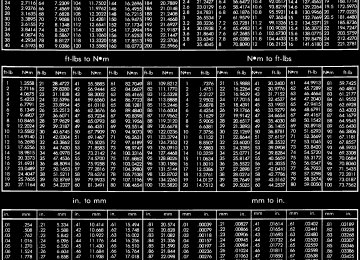
DR FRONT AXLE - 9 1/4 AA (Continued) SPECIFICATIONS
AXLE SPECIFICATIONS
FRONT AXLE - 9 1/4 AA
3 - 53
DESCRIPTION
Axle Ratio
Ring Gear Diameter Ring Gear Backlash
Pinion Bearing Preload - New Bearing
Pinion Bearing Preload - Original Bearing
Pinion Bearing Preload + Differential Case Bearing
Preload - New Bearing
Pinion Bearing Preload + Differential Case Bearing
Preload - Original Bearing
SPECIFICATION
3.73, 4.10
235 mm (9.25 in.)
0.13-0.18 mm (0.005-0.007 in.)
1.7-2.8 N·m (15-25 in. lbs.) 1.1-2.2 N·m (10-20 in. lbs.)
3.4-5.6 N·m (30-50 in. lbs.)
2.8-5.1 N·m (25-45 in. lbs.)
TORQUE SPECIFICATIONS
DESCRIPTION Fill Hole Plug
Differential Cover Bolts
Bearing Cap Bolts Ring Gear Bolts
Axle Nut
Pinion Shaft Lock Bolt
Adjuster Lock Bolt
SPECIAL TOOLS
N·m 32
40
85
140
356
52
25Ft. Lbs.
In. Lbs.
24
30
63
103
263
38
18INSTALLERC-3095-A
DIALINDICATORSTUDL-4438
DIALINDICATORSETC-3339
HANDLEC-4171
FRONT AXLE - 9 1/4 AA
3 - 54
FRONT AXLE - 9 1/4 AA (Continued)DR
SEALINSTALLER8882
PINIONDEPTHSET6730
INSTALLERD-146
ARBORDISCS8289
SPLITTER1130
BRIDGE938
PINIONBLOCK8878
BEARINGINSTALLER8881
DR FRONT AXLE - 9 1/4 AA (Continued)
FRONT AXLE - 9 1/4 AA
3 - 55
PINIONINSTALLER8982
SEALINSTALLER8885
REMOVER/EXTRACTOR6310
RECEIVER8498
PULLERC-293-PA
CUPINSTALLER8886
PINIONDRIVER8976
PLUG8888
FRONT AXLE - 9 1/4 AA
3 - 56
FRONT AXLE - 9 1/4 AA (Continued)DR
AXLE SHAFTS REMOVAL
(1) Remove wheel and tire assembly. (2) Remove brake caliper, rotor and ABS wheel
speed sensor if equipped.
(3) Remove axle shaft cotter pin, hub nut and
washer (Fig. 14).
ADAPTERS8879
ADJUSTERWRENCH8883
Fig.14AXLENUT
1 - AXLE NUT 2 - AXLE 3 - COTTER PIN
(4) Remove the four hub bearing bolts (Fig. 15)
from the back of the steering knuckle.
(5) Remove hub bearing from the steering knuckle. (6) Remove axle shaft from steering knuckle and axle housing.
(Fig. 16)
FLANGEWRENCH8979
FLANGEPULLER8992
DISASSEMBLY
Single cardan U-joint components are not service-
able. If defective they must be replaced as a unit.
CAUTION: Clamp only the narrow forged portion of the yoke in the vise. To avoid distorting the yoke, do not over tighten the vise jaws.
(1) Remove the bearing cap retaining snap rings
(Fig. 17).
NOTE: Saturate the bearing caps with penetrating oil prior to removal.
(2) Locate a socket with an inside diameter that is larger than the bearing cap. Place the socket (receiv- er) against the yoke and around the perimeter of the bearing cap to be removed.
DR AXLE SHAFTS (Continued)
FRONT AXLE - 9 1/4 AA
3 - 57
Fig.15HUBBEARINGBOLTS
1 - STUB SHAFT 2 - BEARING BOLTS 3 - AXLE SHAFT
Fig.17AXLESHAFTOUTERU-JOINT
1 - SHAFT YOKE 2 - BEARING CAP 3 - SNAP RINGS 4 - BEARING CAP 5 - SPINDLE YOKE 6 - BEARING 7 - BEARING CAP 8 - SNAP RINGS 9 - BEARING CAP
Fig.16STEERINGKNUCKLE
1 - KNUCKLE 2 - AXLE SHAFT
(3) Locate a socket with an outside diameter that is smaller than the bearing cap. Place the socket (driver) against the opposite bearing cap.
(4) Position the yoke with the sockets in a vise
(Fig. 18).
(5) Tighten the vise jaws to force the bearing cap
into the larger socket (receiver).
(6) Release the vise jaws. Remove the sockets and bearing cap that was partially forced out of the yoke.
Fig.18YOKEBEARINGCAP
1 - LARGE-DIAMETER SOCKET WRENCH 2 - VISE 3 - SMALL-DIAMETER SOCKET WRENCH
(7) Repeat the above procedure for the remaining bearing cap and remove spider from the propeller shaft yoke.
FRONT AXLE - 9 1/4 AA
3 - 58
AXLE SHAFTS (Continued) ASSEMBLY(1) Pack the bearing caps 1/3 full of wheel bearing lubricant. Apply extreme pressure (EP), lithium-base lubricant to aid in installation.
(2) Position the spider in the yoke. Insert the seals and bearings. Tap the bearing caps into the yoke bores far enough to hold the spider in position.
(3) Place the socket (driver) against one bearing
cap. Position the yoke with the socket in a vise.
(4) Tighten the vise to force the bearing caps into the yoke. Force the caps enough to install the retain- ing clips.
(5) Install the bearing cap retaining clips. (6) Install axle shaft.
INSTALLATION
(1) Clean axle shaft and apply a thin film of Mopar Wheel Bearing Grease to the shaft splines and hub bore.
(2) Install axle shaft through the steering knuckle
and into the differential side gears (Fig. 19).
CAUTION: Do not damage axle shaft seal during axle installtion.
Fig.19AXLESHAFT
1 - AXLE YOKE 2 - AXLE SHAFT 3 - KNUCKLE
(3) Install hub bearing in the knuckle. (4) Install hub bearing bolts and tighten to 202
N·m (149 ft. lbs.).
and caliper.
(5) Install ABS wheel speed sensor, brake rotor
(6) Install axle washer and nut. Tighten axle nut
to 179 N·m (132 ft. lbs.).
DR
(7) Rotate axle several 5 to 10 times to seat the
wheel bearing.
(263 ft. lbs.).
new cotter pin.
(8) Tighten axle nut to final torque of 356 N·m
(9) Align nut to next cotter pin hole and install
(10) Install wheel and tire assembly.
AXLE SHAFT SEALS REMOVAL
(1) Remove hub bearings and axle shafts. (2) Remove differential from differential housing. (3) Remove differential bearing adjusters (Fig. 20).
Fig.20ADJUSTERS
1 - DIFFERENTIAL CASE BEARING ADJUSTERS 2 - DIFFERENTIAL HOUSING
(4) Remove axle seals (Fig. 21)
located behind
adjusters with Receiver 8498 and Extractor 6310. (5) Install Receiver 8498 into the adjuster bore. (6) Install Extractor Rod 6310 with Extractor Foot 6310-9 through the receiver and the axle seal (Fig. 22).
(7) Install Extractor Plate 6310-2 and Nut 6310-7
on the extractor rod.
(8) Tighten nut on the extractor rod (Fig. 23) and
pull the seal out and into the receiver.
INSTALLATION
(1) Install axle seal on Installer Cups 8885-2 and
position cups with seals into the housing.
NOTE: Seal are installed with the axle guide facing outward.
DR AXLE SHAFT SEALS (Continued)
FRONT AXLE - 9 1/4 AA
3 - 59
Fig.21AXLESHAFTSEAL
Fig.23SEALEXTRACTOR
1 - ADJUSTER THREADS 2 - SEAL
1 - EXTRACTOR ROD 2 - EXTRACTOR NUT
Fig.22SEALRECEIVER
Fig.24AXLESEALINSTALLER
1 - RECEIVER 2 - EXTRACTOR FOOT
1 - INSTALLER CUP 2 - INSTALLER TURNBUCKLE 3 - INSTALLER CUP
(2) Install Turnbuckle 8885-1 (Fig. 24)
into the installer cups and expand the turnbuckle until the seal bottom out in the housing.
(3) Install differential into the axle housing. (4) Install axle shaft and hub bearings
3 - 60
FRONT AXLE - 9 1/4 AA
DR
PINION SEAL REMOVAL
(7) Remove pinion flange with Pinion Flange
Puller 8992 (Fig. 27).
(1) Mark the propeller shaft and pinion flange for
installation reference.
(2) Remove propeller shaft. (3) Remove hub bearings and axle shafts. (4) Rotate pinion gear three or four times. (5) Measure and record the torque necessary to rotate (Fig. 25) the pinion gear with an inch pound torque wrench.
Fig.27PINIONFLANGEPULLER
1 - PINION FLANGE 2 - PULLER
(8) Remove pinion shaft seal with a pry tool or
slide hammer mounted screw.
INSTALLATION
(1) Install new pinion seal with Installer 8882 and
Handle C-4171 (Fig. 28).
Fig.25PINIONROTATINGTORQUE
1 - PINION FLANGE 2 - TORQUE WRENCH
(6) Hold pinion flange with Flange Wrench 8979
(Fig. 26) and remove pinion flange nut and washer.Fig.28PINIONSEALINSTALLER
1 - HANDLE 2 - INSTALLER
(2) Apply a light coat of teflon thread sealant to
the pinion flange splines.
(3) Lightly tap the pinion flange onto the pinion
until a few threads are showing.
(4) Install flange washer and new pinion nut. (5) Hold flange with Flange Wrench 8979 and tighten pinion nut until pinion end play is taken up.
(6) Rotate pinion several times to seat bearings. (7) Measure pinion rotating torque with an inch pound torque wrench and compare it to recorded measurement. Tighten pinion nut in small incre-
Fig.26FLANGEWRENCH
1 - PINION FLANGE 2 - WRENCH
DR PINION SEAL (Continued)
ments, until pinion rotating torque is 0.40-0.57 N·m (3-5 in. lbs.) greater than recorded measurement.
(8) Rotate pinion several times then verify pinion
rotating torque again.
(9) Install axle shafts and hub bearings. (10) Install propeller shaft with reference marks
aligned.
DIFFERENTIAL DESCRIPTION
The differential case is a one-piece design. The dif- ferential pinion shaft is retained with a snap ring. Differential bearing preload and ring gear backlash is adjusted by the use of adjusters. The adjuster are between the differential bearings and the differential housing. Pinion bearing preload is set and main- tained by the use of a collapsible spacer. The stamped steel cover provides a means for inspection and servicing the differential.
OPERATION
During straight-ahead driving, the differential pin- ion gears do not rotate on the pinion mate shaft. This occurs because input torque applied to the gears is divided and distributed equally between the two side gears. As a result, the pinion gears revolve with the pinion mate shaft but do not rotate around it (Fig. 29).
FRONT AXLE - 9 1/4 AA
3 - 61
pinion gears is not divided equally. The pinion gears now rotate around the pinion mate shaft in opposite directions. This allows the side gear and axle shaft attached to the outside wheel to rotate at a faster speed.
Fig.30DIFFERENTIAL-ONTURNS
1 - PINION GEARS ROTATE ON PINION SHAFT
REMOVAL
(1) Remove differential housing cover and drain
lubricant from the housing.
(2) Remove hub bearings and axle shafts. (3) Remove adjuster lock bolts and adjuster locks
(Fig. 31).
Fig.29DIFFERENTIAL-STRAIGHTAHEADDRIVING 1 - IN STRAIGHT AHEAD DRIVING EACH WHEEL ROTATES AT 100% OF CASE SPEED 2 - PINION GEAR 3 - SIDE GEAR 4 - PINION GEARS ROTATE WITH CASE
When turning corners, the outside wheel must travel a greater distance than the inside wheel to complete a turn. To accomplish this, the differential allows the axle shafts to turn at unequal speeds (Fig. 30). In this instance, the input torque applied to the
Fig.31ADJUSTERSANDLOCKS
1 - ADJUSTER LOCK BOLT 2 - ADJUSTER LOCK 3 - ADJUSTER 4 - BEARING CAP
3 - 62
FRONT AXLE - 9 1/4 AA DIFFERENTIAL (Continued)(4) Mark bearing caps left and right for installa-
(5) Remove bearing cap bolts and remove bearing
tion reference.
caps.
(6) Loosen differential bearing adjusters (Fig. 32)
with Spanner Wrench 8883.
DR
(3) Rotate differential pinion gears to differential window and remove pinion gears and thrust washers (Fig. 34).
Fig.34PINIONGEAR
1 - DIFFERENTIAL WINDOW 2 - PINION GEAR 3 - THRUST GEAR
(4) Remove differential side gears and thrust
washers (Fig. 35).
Fig.32ADJUSTERS
1 - BEARING CUP 2 - ADJUSTER 3 - BEARING CUP 4 - ADJUSTER
(7) Remove differential case from the housing. (8) Remove bearing cups and tag them left and
right for installation reference.
DISASSEMBLY
(1) Remove pinion shaft lock bolt. (2) Remove pinion shaft (Fig. 33).
Fig.35SIDEGEARS
1 - SIDE GEAR 2 - SIDE GEAR 3 - PINION GEARS
Fig.33PINIONSHAFT
1 - PINION SHAFT 2 - PUNCH 3 - PINION GEAR 4 - SIDE GEAR
DR DIFFERENTIAL (Continued) ASSEMBLY NOTE: If the same gears and thrust washers are being used, install them into their orignial locations.
(1) Lubricate all differential components with axle
to 52 N·m (38 ft. lbs.).
lubricant.
ers (Fig. 36).
(2) Install differential side gears and thrust wash-
FRONT AXLE - 9 1/4 AA
3 - 63
(4) Align hole in the pinion gears with hole in the
differential case.
(5) Install pinion shaft. (6) Install new pinion shaft lock bolt and tighten
INSTALLATION
(1) Clean the housing cavity with a flushing oil,
light engine oil or lint free cloth.
CAUTION: Do not use water, steam, kerosene or gasoline for cleaning.
(2) Lubricate differential case bearing. (3) Install differential case with bearings cups into
the housing.
(4) Install bearing caps and bolts (Fig. 38). Tighten
the bearing cap bolts finger-tight.
NOTE: Do not torque bearing cap and bolts at this time.
Fig.36SIDEGEARS
1 - DIFFERENTIAL WINDOW 2 - SIDE GEAR
(3) Rotate the one pinion gear with thrust washer into the differential case (Fig. 37). Then rotate the other pinion gear with thrust washer into the differ- ential case.
Fig.38CASEBEARINGCAP
1 - DIFFERENTIAL HOUSING 2 - BEARING CAP 3 - ADJUSTER
(5) Slide differential case toward the pinion gear until the gears make contact/zero backlash. If zero backlash cannot be obtained, turn the pinion side adjuster until zero backlash is obtained.
(6) Holding the differential case toward the pinion gear, turn bearing adjusters with Spanner Wrench 8883 until they make contact with the differential bearings/cups.
Fig.37PINIONGEAR
1 - DIFFERENTIAL WINDOW 2 - SIDE GEARS 3 - PINION GEAR
3 - 64
FRONT AXLE - 9 1/4 AA