- 2009 Dodge RAM Diesel Owners Manuals
- Dodge RAM Diesel Owners Manuals
- 2010 Dodge RAM Diesel Owners Manuals
- Dodge RAM Diesel Owners Manuals
- 2005 Dodge RAM Diesel Owners Manuals
- Dodge RAM Diesel Owners Manuals
- 2006 Dodge RAM Diesel Owners Manuals
- Dodge RAM Diesel Owners Manuals
- 2008 Dodge RAM Diesel Owners Manuals
- Dodge RAM Diesel Owners Manuals
- 2004 Dodge RAM Diesel Owners Manuals
- Dodge RAM Diesel Owners Manuals
- 2007 Dodge RAM Diesel Owners Manuals
- Dodge RAM Diesel Owners Manuals
- Download PDF Manual
-
Methods For Removing Snow
Operating Tips Under ideal snow plowing conditions, 20 mph (32 km/h) should be maximum operating speed. The operator should be familiar with the area and surface to be cleaned. Reduce speed and use extreme caution when plowing unfamiliar areas or under poor visibility.
374 STARTING AND OPERATING
NOTE: During snowplow usage on vehicles equipped with an overhead console module, the outside tempera- ture display will show higher temperatures than the outside ambient temperature. The higher displayed tem- perature is due to blocked or reduced airflow to the underhood ambient temperature sensor by the snow- plow. This is common and outside temperature display operation will return to normal when the snowplow is removed. General Maintenance Snowplows should be maintained in accordance with the plow manufacturer’s instructions. Keep all snowplow electrical connections and battery terminals clean and free of corrosion.
When plowing snow, to avoid transmission and driv- etrain damage, the following precautions should be ob- served. † Operate with transfer case in 4L when plowing small or congested areas where speeds are not likely to exceed 15 mph (24 km/h). At higher speeds operate in 4H. † Vehicles with 68RFE transmissions should use 4L range when plowing deep or heavy snow for extended periods of time to avoid transmission overheating. † Do not shift the transmission unless the engine has returned to idle and wheels have stopped. Make a practice of stepping on the brake pedal before shifting the transmission.
RECREATIONAL TOWING (BEHIND MOTORHOME, ETC.)
CAUTION!
Front or rear wheel lifts should not be used. Internal damage to the transmission or transfer case will occur if a front or rear wheel lift is used when recreational towing.
Recreational Towing – 2-Wheel Drive Models
Recreational towing of 2-Wheel Drive models is not allowed. Towing with the rear wheels on the ground can result in severe transmission damage.
STARTING AND OPERATING 375
Recreational Towing – 4-Wheel Drive Models
CAUTION!
Failure to follow these requirements can cause severe damage to the transmission and/or transfer case.
NOTE: Both the Manual Shift and Electronic Shift transfer cases must be shifted into NEUTRAL for recre- ational towing. Automatic transmissions must be shifted into PARK position for recreational towing. Manual transmissions must be left in gear (not in NEUTRAL) for recreational towing. Refer to the following for the proper transfer case NEUTRAL shifting procedure for your vehicle.
376 STARTING AND OPERATING
Recreational Towing Procedure — Manual Shift Transfer Case — If Equipped Use the following procedure to prepare your vehicle for recreational towing:
CAUTION!
It is necessary to follow these steps to be certain that the transfer case is fully in NEUTRAL before recre- ational towing to prevent damage to internal parts.
1. Bring the vehicle to a complete stop. 2. Shut OFF the engine. 3. Depress the brake pedal. 4. Shift automatic transmission to NEUTRAL, or depress the clutch on manual transmissions.
5. Shift transfer case lever into NEUTRAL. 6. Start the engine. 7. Shift automatic transmission into REVERSE. 8. Release brake pedal for five seconds and ensure that there is no vehicle movement. 9. Repeat steps 7 and 8 with the transmission in DRIVE. 10. Shut OFF the engine and place the ignition key in the unlocked OFF position. 11. Shift automatic transmission into PARK or 1st gear on manual transmissions. 12. Apply the parking brake. 13. Attach vehicle to tow vehicle with tow bar. 14. Release the parking brake.
CAUTION!
Damage to the automatic transmission may occur if the transmission is shifted into PARK with the trans- fer case in NEUTRAL and the engine running. With the transfer case in NEUTRAL ensure that the engine is OFF prior to shifting the transmission into PARK.
Returning to Normal Operation — Manual Shift Transfer Case Use the following procedure to prepare your vehicle for normal usage: 1. Bring the vehicle to a complete stop. 2. Apply the parking brake. 3. Shut OFF the engine. 4. Depress the brake pedal.
STARTING AND OPERATING 377
5. Shift automatic transmission to NEUTRAL, or depress the clutch on manual transmissions. 6. Shift transfer case lever to desired position. 7. Shift automatic transmission into PARK.
WARNING!
You or others could be injured if you leave the vehicle unattended with the transfer case in the NEUTRAL position without first fully engaging the parking brake. The transfer case NEUTRAL position disengages both the front and rear driveshafts from the powertrain and will allow the vehicle to move, regardless of the transmission position. The parking brake should always be applied when the driver is not in the vehicle.
378 STARTING AND OPERATING
CAUTION!
† Do not use a bumper-mounted clamp-on tow bar on your vehicle. The bumper face bar will be damaged. † Do not disconnect the rear driveshaft because fluid will leak from the transfer case and damage the internal parts.
Recreational Towing Procedure — Electronic Shift Transfer Case — If Equipped Use the following procedure to prepare your vehicle for recreational towing:
CAUTION!
It is necessary to follow these steps to be certain that the transfer case is fully in NEUTRAL before recre- ational towing, to prevent damage to internal parts.
1. Bring vehicle to a complete stop. 2. Shut OFF the engine. 3. Turn the ignition key to the ON position, but do not start the engine. 4. Depress the brake pedal. 5. Shift automatic transmission to NEUTRAL or depress clutch on manual transmission. 6. Using the point of a ballpoint pen or similar object, depress the recessed transfer case NEUTRAL button for four seconds.
7. After shift is completed and the NEUTRAL light comes on, release the NEUTRAL button. 8. Start engine. 9. Shift automatic transmission into REVERSE. 10. Release brake pedal for five seconds and ensure that there is no vehicle movement. 11. Repeat steps 9 and 10 with the transmission in DRIVE. 12. Shut engine OFF and place ignition key in the unlocked OFF position. 13. Shift automatic transmission into PARK or 1st gear on manual transmissions. 14. Apply parking brake. 15. Attach vehicle to tow vehicle with tow bar. 16. Release parking brake.
STARTING AND OPERATING 379
NOTE: Steps 1 through 5 are requirements that must be met prior to depressing the NEUTRAL selection button, and must continue to be met until the four seconds elapses and the shift has been completed. If any of these requirements (with the exception of 3 - Key ON) are not met prior to depressing the NEUTRAL button or are no longer met during the four second timer, then the NEU- TRAL indicator light will flash continuously until all requirements are met or until the NEUTRAL button is released. NOTE: The ignition key must be ON for a shift to take place and for the position indicator lights to be operable. If the key in not ON, the shift will not take place and no position indicator lights will be on or flashing. NOTE: indicates that shift requirements have not been met.
Flashing NEUTRAL position indicator light
380 STARTING AND OPERATING
CAUTION!
Damage to the transmission may occur if the trans- mission is shifted into PARK with the transfer case in NEUTRAL and the engine running. With the transfer case in NEUTRAL ensure, that the engine is OFF prior to shifting the transmission into PARK.
Returning to Normal Operation — Electronic Shift Transfer Case Use the following procedure to prepare your vehicle for normal usage: 1. Bring vehicle to a complete stop. 2. Shut OFF the engine. 3. Turn the ignition key to the ON position, but do not start the engine.
4. Depress the brake pedal. 5. Shift automatic transmission to NEUTRAL or depress clutch on manual transmission. 6. Using the point of a ballpoint pen or similar object, depress the recessed transfer case Neutral (N) button for one second. 7. After the Neutral indicator light turns off, release the Neutral (N) button. 8. After the Neutral (N) button has been released, the transfer case will shift to the position identified by the selector switch. 9. Shift automatic transmission into PARK. NOTE: The transfer case cannot be shifted into NEU- TRAL from the 4AUTO (if equipped) position.
NOTE: Steps 1 through 5 are requirements that must be met prior to depressing the transfer case Neutral (N) button, and must continue to be met until one second elapses and the shift has been completed. If any of these requirements (with the exception of step 3 - key ON) are not met prior to depressing the Neutral (N) button, or are no longer met during the one second time, then all of the mode position indicator lights will flash continuously until all requirements are met, or until the Neutral (N) button is released.
STARTING AND OPERATING 381
NOTE: The ignition key must be ON for a transfer case shift to take place and for the position indicator lights to be operable. If the key is not ON, the shift will not take place and no position indicator lights will be on or flashing. NOTE: Flashing Neutral position indicator light indi- cates that shift requirements have not been met.
382 STARTING AND OPERATING
WARNING!
You or others could be injured if you leave the vehicle unattended with the transfer case in the NEUTRAL position without first fully engaging the parking brake. The transfer case NEUTRAL position disengages both the front and rear driveshafts from the powertrain and will allow the vehicle to move despite the transmission position. The parking brake should always be applied when the driver is not in the vehicle.
CAUTION!
† Do not use a bumper-mounted clamp-on tow bar on your vehicle. The bumper face bar will be damaged. † Do not disconnect the rear driveshaft because fluid will leak from the transfer case and fluid loss will damage internal parts.
WHAT TO DO IN EMERGENCIES
CONTENTS
m Hazard Warning Flasher . . . . . . . . . . . . . . . . . . 384
m Jacking And Tire Changing . . . . . . . . . . . . . . . . 385
N All Models – If Equipped . . . . . . . . . . . . . . . 385
m Jacking Instructions . . . . . . . . . . . . . . . . . . . . . 386
N Removing The Spare Tire . . . . . . . . . . . . . . . . 386
N Tire Changing Procedure . . . . . . . . . . . . . . . . 387
m Hoisting . . . . . . . . . . . . . . . . . . . . . . . . . . . . . 396N With Portable Starting Unit
m Jump-Starting . . . . . . . . . . . . . . . . . . . . . . . . . 397
. . . . . . . . . . . . . . 400
m Freeing A Stuck Vehicle . . . . . . . . . . . . . . . . . . 400
m Emergency Tow Hooks — If Equipped . . . . . . . . 401
m Towing A Disabled Vehicle . . . . . . . . . . . . . . . . 402
N 4-Wheel Drive Vehicles . . . . . . . . . . . . . . . . . 402
N 2–Wheel Drive Vehicles . . . . . . . . . . . . . . . . . 403384 WHAT TO DO IN EMERGENCIES
HAZARD WARNING FLASHER The Hazard Warning switch is mounted on the top of the steering column as shown in the illustration.
Hazard Light Warning Switch
To engage the Hazard Warning lights, depress the button on the top of the steering column. When the Hazard Warning switch is activated, all directional turn signals will flash off and on to warn oncoming traffic of an emergency. Push the button a second time to turn off the flashers. This is an emergency warning system and should not be used when the vehicle is in motion. Use it when your vehicle is disabled and is creating a safety hazard for other motorists. When you must leave the vehicle to seek assistance, the Hazard Warning lights will continue to operate even though the ignition switch is OFF. NOTE: With extended use, the Hazard Warning lights may discharge your battery.
JACKING AND TIRE CHANGING
WARNING!
† Being under a jacked-up vehicle is dangerous. The vehicle could slip off the jack and fall on you. You could be crushed. Never put any part of your body under a vehicle that is on a jack. Never start or run the engine while the vehicle is on a jack. If you need to get under a raised vehicle, take it to a service center where it can be raised on a lift. † The jack is designed to use as a tool for changing tires only. The jack should not be used to lift the vehicle for service purposes. The vehicle should be jacked on a firm level surface only. Avoid ice or slippery areas.
WHAT TO DO IN EMERGENCIES 385
All Models – If Equipped The jack and jack tools are stored under the front passenger seat. Lift the flap on the side of the seat for access. Remove the jack and tools by removing the wing bolt and sliding the assembly from under the seat.
Jack Location
386 WHAT TO DO IN EMERGENCIES
WARNING!
After using the jack and tools, always reinstall them in the original carrier and location. While driving you may experience, abrupt stopping, rapid accelera- tion, or sharp turns. A loose jack, tools, bracket or other objects in the vehicle may move around with force, resulting in serious injury.
JACKING INSTRUCTIONS
Removing The Spare Tire Remove the spare tire before attempting to jack the truck. Attach the wheel wrench to the jack extension tube. Insert the tube through the access hole between the lower tailgate and the top of the bumper and into the winch mechanism tube. Rotate the wheel wrench handle coun- terclockwise until the spare tire is on the ground with enough cable slack to allow you to pull it out from under
the vehicle. When the spare is clear, tilt the retainer at the end of the cable and pull it through the center of the wheel.
It is recommended that you stow the flat or spare to avoid tangling the loose cable.
NOTE: The winch mechanism is designed for use with the jack extension tube only. Use of an air wrench or other power tools is not recommended and can damage the winch. Tire Changing Procedure
WARNING!
Getting under a jacked-up vehicle is dangerous. The vehicle could slip off the jack and fall on you. You could be crushed. Never get any part of your body under a vehicle that is on a jack. Never start or run the engine while the vehicle is on a jack. If you need to get under a raised vehicle, take it to a service center where it can be raised on a lift.
WHAT TO DO IN EMERGENCIES 387
Do not raise this vehicle using a bumper jack. The jack is designed as a tool for changing tires on this vehicle only. It is not recommended that the jack be used for service purposes or to lift more than one wheel at a time. Preparations Park the vehicle on a firm level surface, avoiding ice or slippery areas. Set the parking brake and place the gear selector in PARK (automatic transmission) or REVERSE (manual transmission). On four-wheel drive vehicles, shift the transfer case to the “4L” position.
WARNING!
Do not attempt to change a tire on the side of the vehicle close to moving traffic. Pull far enough off the road to avoid the danger of being hit when operating the jack or changing the wheel.
388 WHAT TO DO IN EMERGENCIES
† Turn on the Hazard Warning Flasher.
† Block both the front and rear of the wheel diagonally oppo- site the jacking position. For example, front wheel is being changed, block the left rear wheel. † Passengers should not remain in the vehicle when the
the right
if
vehicle is being jacked.
Instructions
Jack Warning Label
WARNING!
be raised.
Carefully follow these tire changing warnings to help prevent personal injury or damage to your vehicle: † Always park on a firm, level surface as far from the edge of the roadway as possible before raising the vehicle. † Block the wheel diagonally opposite the wheel to † Apply the parking brake firmly before jacking. † Never start the engine with the vehicle on a jack. † Do not let anyone sit in the vehicle when it is on a † Do not get under the vehicle when it is on a jack. † Only use the jack in the positions indicated. † If working on or near a roadway, be extremely
jack.
careful of motor traffic.
1. Remove the spare wheel, jack, and tools from storage. 2. Using the wheel wrench, loosen, but do not remove, the wheel nuts by turning them counterclockwise one turn while the wheel is still on the ground. 3. For 2500/3500 4x2 series trucks, when changing a front wheel, place the bottle jack under the frame rail behind the wheel. Locate the jack as far forward as possible on the straight part of the frame. For 2500/3500 4x4 series trucks, when changing the front wheel, assemble the jack drive tube to the jack and connect the drive tube to the extension tube. Place the jack under the axle as close to the tire as possible with the drive tubes extending to the front. Connect the jack tube extension and wheel wrench.
WHAT TO DO IN EMERGENCIES 389
When changing a rear wheel, assemble the jack drive tube to the jack and connect the drive tube to the extension tube. Place the jack under the axle between the spring and the shock absorber with the drive tubes extending to the rear. Connect the jack tube extension and wheel wrench. Before raising the wheel off the ground, make sure that the jack will not damage surrounding truck parts and adjust the jack position as required.
390 WHAT TO DO IN EMERGENCIES
If the jack will not lower by turning the dial NOTE: (thumbwheel) by hand, it may be necessary to use the jack drive tube in order to lower the jack.
4X2 Jacking
WHAT TO DO IN EMERGENCIES 391
WARNING!
Raising the vehicle higher than necessary can make the vehicle unstable and cause an accident. It could slip off the jack and hurt someone near it. Raise the vehicle only enough to remove the tire.
5. Remove the wheel nuts and pull the wheel off. Install the spare wheel and wheel nuts with the cone shaped end of the nuts toward the wheel on 2500/3500 single rear wheel (SRW) models. On 3500 dual rear wheel models (DRW) the lug nuts are a two piece assembly with a flat face. Lightly tighten the nuts. To avoid risk of forcing the vehicle off the jack, do not fully tighten the nuts until the vehicle has been lowered.
4. By rotating the wheel wrench clockwise, raise the vehicle until the wheel just clears the surface.
392 WHAT TO DO IN EMERGENCIES
6. Using the wheel wrench, finish tightening the nuts using a crisscross pattern. Correct nut tightness is 135 ft. lbs. (183 N·m) torque for 2500/3500 single rear wheel (SRW) models and 145 ft. lbs. (197 N·m) for 3500 dual rear wheel models. If in doubt about the correct tightness, have them checked with a torque wrench by your dealer or at a service station.
WARNING!
A loose tire or jack thrown forward in a collision or hard stop could injure someone in the vehicle. Al- ways stow the jack parts and the extra tire and wheel in the places provided.
7. Install wheel center cap and remove wheel blocks. Do not install chrome or aluminum wheel center caps on the spare wheel. This may result in cap damage.
8. Lower the jack to its fully closed position. If the jack will not lower by turning the dial (thumbwheel) by hand, it may be necessary to use the jack drive tube in order to lower the jack. Stow the replaced tire, jack, and tools as previously described. 9. Adjust the tire pressure when possible. NOTE: Do not oil wheel studs. For chrome wheels, do not substitute with chrome plated wheel nuts. Hub Caps/Wheel Covers The hub caps must be removed before raising the vehicle off the ground. For 2500/3500 single rear wheel (SRW) models, use the blade on the end of the lug wrench to pry the hub cap off. Insert the blade end into the pryoff notch and carefully pop off the hub cap with a back and forth motion.
On 3500 models with dual rear wheels (DRW), you must first remove the hub caps. The jack handle driver has a hook at one end that will fit in the pry off notch of the rear hub caps. Position the hook and pull out on the ratchet firmly. The hub cap should pop off. The wheel skins can now be removed. For the front hub cap on 3500
models use the blade on the end of the lug wrench to pry the caps off. The wheel skin can now be removed.CAUTION!
Use a back and forth motion to remove the hub cap. Do not use a twisting motion when removing the hub cap, damage to the hub cap finish may occur.
WHAT TO DO IN EMERGENCIES 393
CAUTION!
The rear hub caps on the dual rear wheel has two pry off notches. Make sure that the hook of the jack handle driver is located squarely in the cap notch before attempting to pull off.
You must use the flat end of the lug wrench to pry off the wheel skins. Insert the flat tip completely and using a back and forth motion, loosen the wheel skin. Repeat this procedure around the tire until the skin pops off. Replace the wheel skins first using a rubber mallet. When replacing the hub caps, tilt the cap retainer over the lugnut bolt circle and strike the high side down with a rubber mallet. Be sure that the hub caps and wheel skins are firmly seated around the wheel.
394 WHAT TO DO IN EMERGENCIES
8-Stud — Dual Rear Wheels Dual wheels are flat mounted, center piloted. The lug nuts are a two piece assembly. When the tires are being rotated or replaced, clean these lug nuts and add two drops of oil at the interface between the hex and the washer.
Slots in the wheels will assist in properly orienting the inner and outer wheels. Align these slots when assem- bling the wheels for best access to the tire valve on the inner wheel. The tires of both dual wheels must be completely off the ground when tightening to ensure wheel centering and maximum wheel clamping. Dual wheel models require a special heavy-duty lug nut tightening adapter (included with the vehicle) to cor- rectly tighten the lug nuts. Also, when it is necessary to remove and install dual rear wheels, use a proper vehicle lifting device. NOTE: When installing a spare tire as part of a dual rear wheel end combination, the tire diameter of the two individual tires must be compared. If there is a significant difference, the larger tire should be installed in a front location. Correct direction of rotation for dual tire instal- lations must also be observed.
These dual rear wheels should be tightened as follows:
WHAT TO DO IN EMERGENCIES 395
1. Tighten the wheel nuts in the numbered sequence to a snug fit. 2. Retighten the wheel nuts in the same sequence to the torques listed in the table. Go through the sequence a second time to verify that specific torque has been achieved. Retighten to specifications at 100 mi(160 km) and after 500 mi (800 km). It is recommended that wheel stud nuts be kept torqued to specifications at all times. Torque wheel stud nuts to specifications at each lubrication interval. Wheel Nuts All wheel nuts should be tightened occasionally to elimi- nate the possibility of wheel studs being sheared or the bolt holes in the wheels becoming elongated. This is especially important during the first few hundred miles/ kilometers of operation to allow the wheel nuts to become properly set. All nuts should first be firmly seated against the wheel. The nuts should then be
396 WHAT TO DO IN EMERGENCIES
tightened to recommended torque. Tighten the nuts to final torque in increments. Progress around the bolt circle, tightening the nut opposite to the nut just previ- ously tightened until final torque is achieved. Recom- mended torques are shown in the following chart. Disc Wheels
Type Nut Stud Size Torque Ft. Lbs.
Cone Flanged
9/16-18
9/16-18120-150
130-160To Stow The Flat Or Spare Turn the wheel so that the valve stem is down. Slide the wheel retainer through the center of the wheel and position it properly across the wheel opening. For convenience in checking the spare tire inflation, stow with the valve stem toward the rear of the vehicle.
Torque Newton Meters 160-200
190-220Attach the wheel wrench to the extension tube. Rotate the winch mechanism until the wheel is drawn into place against the underside of the vehicle. Continue to rotate until you feel the winch mechanism slip or click three or four times. It cannot be overtightened. Push against the tire several times to be sure it is firmly in place.
HOISTING A conventional floor jack may be used at the jacking locations. Refer to the graphics that show jacking loca- tions. However, a floor jack or frame hoist must never be used on any other parts or the underbody.
CAUTION!
Never use a floor jack directly under the differential housing of a loaded truck or damage to your vehicle may result.
JUMP-STARTING
WARNING!
To prevent personal injury or damage to clothing, do not allow battery fluid to contact eyes, skin or fabrics. Do not lean over a battery when connecting jumper cables or allow cable clamps to touch each other. Keep open flames or sparks away from battery vent holes. Always wear eye protection when working with batteries. Do not use a booster battery or any other booster source that has a greater than 12-volt system, i.e., do not use a 24-volt power source.
WHAT TO DO IN EMERGENCIES 397
NOTE: Replacement batteries should both be of equal size to prevent damage to the vehicle’s charging system. Your vehicle is equipped with two 12–volt batteries. If it becomes necessary to use a booster battery with jumper cables to start a vehicle’s engine because its batteries are discharged, the following procedure should be used: Set the parking brake and place an automatic transmis- sion in PARK (or NEUTRAL for a manual transmission). Turn off lights, heater and other electrical loads. Observe charge indicator (if equipped) in both batteries. If indica- tor (if equipped) is light or yellow on either battery, replace that battery.
398 WHAT TO DO IN EMERGENCIES
CAUTION!
WARNING!
Do not permit vehicles to touch each other as this could establish a ground connection and personal injury could result.
Use the Jump-Start Procedure only when the charge indicator (if equipped) in both batteries is dark in the center. Do not attempt jump-starting when either battery charge indicator (if equipped) is bright or yellow. If charge indicator (if equipped) has a green dot in the center, failure to start is not due to a discharged battery and cranking system should be checked.
1. Attach one jumper cable to the positive terminal of booster battery and the other end of the same cable to the positive terminal of the discharged battery.
2. Connect one end of the other jumper cable to negative (-) post of booster battery. Connect the other end of the jumper cable to a good ground on the engine block of the vehicle with the discharged battery. Make sure a good connection is made, free of dirt and grease.
WARNING!
† Do not connect the cable to the negative post of the discharge battery. The resulting electrical spark could cause the battery to explode. † During cold weather when temperatures are be- low freezing point, electrolyte in a discharged battery may freeze. Do not attempt jump-starting because the battery could rupture or explode. The battery temperature must be brought up above freezing point before attempting to jump-start.
WHAT TO DO IN EMERGENCIES 399
3. Take care that the clamps from one cable do not inadvertently touch clamps from the other cable. Do not lean over the battery when making connection. The negative connection must provide good electrical con- ductivity and current carrying capacity. 4. After the engine is started or if the engine fails to start, cables must be disconnected in the following order:
a. Disconnect the negative cable at the engine ground. b. Disconnect the negative cable at the negative post on booster battery. c. Disconnect the cable from the positive post of both batteries.
400 WHAT TO DO IN EMERGENCIES
WARNING!
CAUTION!
Any procedure other than above could result in: 1. Personal injury caused by electrolyte squirting out the battery vent; 2. Personal injury or property damage due to battery explosion; 3. Damage to charging system of booster vehicle or of immobilized vehicle.
With Portable Starting Unit There are many types of these units available. Follow the manufacturer’s instructions for necessary precautions and operation.
It is very important that the starting unit operating voltage does not exceed 12-Volts DC or damage to battery, starter motor, alternator, or electrical system may occur.
FREEING A STUCK VEHICLE If the vehicle becomes stuck in snow, sand, or mud, it can often be moved by a rocking motion. Move the gear selector rhythmically between DRIVE and REVERSE (automatic transmissions) or between 1st and REVERSE (manual transmissions), while applying slight pressure to the accelerator.
In general, the least amount of accelerator pedal pressure to maintain the rocking motion without spinning the wheels or racing the engine, is most effective. Racing the engine or spinning the wheels, due to the frustration of not freeing the vehicle, may lead to transmission over- heating and failure. Allow the engine to idle with the transmission selector in NEUTRAL for at least one minute after every five rocking-motion cycles. This will minimize overheating and reduce the risk of transmis- sion failure during prolonged efforts to free a stuck vehicle.
EMERGENCY TOW HOOKS — IF EQUIPPED Your vehicle may be equipped with emergency tow hooks.
WHAT TO DO IN EMERGENCIES 401
NOTE: For off-road recovery, it is recommended to use both of the front tow hooks to minimize the risk of damage to the vehicle.
WARNING!
Chains are not recommended for freeing a stuck vehicle. Chains may break, causing serious injury or death.
WARNING!
Stand clear of vehicles when pulling with tow hooks. Tow straps and chains may break, causing serious injury.
402 WHAT TO DO IN EMERGENCIES
CAUTION!
4-Wheel Drive Vehicles
Tow hooks are for emergency use only, to rescue a vehicle stranded off-road. Do not use tow hooks for tow truck hookup or highway towing. You could damage your vehicle.
CAUTION!
To avoid damage to the transfer case while towing, always use one of the following methods.
TOWING A DISABLED VEHICLE Proper towing or lifting equipment is required to prevent damage to your vehicle. Use only tow bars and other equipment designed for the purpose, following equip- ment manufacturer’s instructions. Use of safety chains is mandatory. Attach a tow bar or other towing device to the main structural members of the vehicle—not to bumpers or associated brackets. State and local laws applying to vehicles under tow must be observed.
NOTE: The transfer case must be in the neutral position, and the transmission must be in PARK (automatic trans- mission), or in gear (manual transmission) to tow a 4WD vehicle with one end of the vehicle raised. The manufacturer recommends towing with all wheels OFF the ground. Acceptable methods are to tow the vehicle on a flatbed or with one end of vehicle raised and the opposite end on a towing dolly.
2–Wheel Drive Vehicles Provided that the transmission is operable, tow with the transmission in NEUTRAL and the ignition key in the OFF position along with the front wheels raised and the rear wheels on the ground. Speed must not exceed 30
mph (50 km/h) and distance must not exceed 15 mi (25
km).CAUTION!
Towing faster than 30 mph (50 km/h) or for more than 15 mi (25 km) can cause severe damage to the transmission.
WHAT TO DO IN EMERGENCIES 403
If the vehicle is to be towed faster than 30 mph (50 km/h) or more than 15 mi (25 km) the vehicle must be towed with the rear wheels raised and the front wheels on the ground. It may also be towed on a flatbed or with the front wheels raised and the rear wheels on a dolly.
MAINTAINING YOUR VEHICLE
CONTENTS
m Engine Compartment — 6.7L Diesel Engine . . . . 408
m Onboard Diagnostic System (OBD II) . . . . . . . . . 409
m Replacement Parts . . . . . . . . . . . . . . . . . . . . . . 409
m Engine Data Plate . . . . . . . . . . . . . . . . . . . . . . 410
m Authorized Dealer Service . . . . . . . . . . . . . . . . 410
m Service Information . . . . . . . . . . . . . . . . . . . . . 410
m Maintenance Procedures . . . . . . . . . . . . . . . . . . 412
N Engine Oil . . . . . . . . . . . . . . . . . . . . . . . . . . 413
N Drive Belt . . . . . . . . . . . . . . . . . . . . . . . . . . . 418N Engine Air Cleaner Filter (6.7L Diesel
Engines) . . . . . . . . . . . . . . . . . . . . . . . . . . . . 419
N Draining Fuel/Water Separator Filter (6.7L
Diesel Engine)
. . . . . . . . . . . . . . . . . . . . . . . 422
N Intervention Regeneration Strategy – EVIC
Message Process Flow (Catalyst Full Message) (6.7L Diesel Engines Only) . . . . . . . . . . . . . . . 425
N Maintenance Free Batteries . . . . . . . . . . . . . . . 428
N Air Conditioner Maintenance . . . . . . . . . . . . . 430
N Power Steering — Fluid Check . . . . . . . . . . . . 431406 MAINTAINING YOUR VEHICLE
N Front Suspension Ball Joints . . . . . . . . . . . . . . 431
N Steering Linkage — Inspection . . . . . . . . . . . . 432
N Front Prop Shaft Lubrication . . . . . . . . . . . . . 432
N Front Axle Universal Drive Joints And BallJoints . . . . . . . . . . . . . . . . . . . . . . . . . . . . . . 432
N Body Lubrication . . . . . . . . . . . . . . . . . . . . . 433
N Windshield Wiper Blades . . . . . . . . . . . . . . . . 433
N Windshield Washers . . . . . . . . . . . . . . . . . . . 434
N Exhaust System . . . . . . . . . . . . . . . . . . . . . . 435
N Cooling System . . . . . . . . . . . . . . . . . . . . . . . 436
N Fan . . . . . . . . . . . . . . . . . . . . . . . . . . . . . . . 442
N Charge Air Cooler (Inter-Cooler) . . . . . . . . . . 442
N Hoses And Vacuum/Vapor Harnesses . . . . . . . 443N Brake System . . . . . . . . . . . . . . . . . . . . . . . . 443
N Clutch Linkage . . . . . . . . . . . . . . . . . . . . . . . 445
N Clutch Hydraulic System . . . . . . . . . . . . . . . . 445
N Rear Axle And 4X4 Front Driving Axle FluidLevel . . . . . . . . . . . . . . . . . . . . . . . . . . . . . . 446
N Transfer Case — If Equipped . . . . . . . . . . . . . 446
N Manual Transmission — If Equipped . . . . . . . 447
N Automatic Transmission . . . . . . . . . . . . . . . . 447
N Front Wheel Bearings . . . . . . . . . . . . . . . . . . 450
N Noise Control System Required Maintenance& Warranty . . . . . . . . . . . . . . . . . . . . . . . . . 451
N Appearance Care And Protection From
Corrosion . . . . . . . . . . . . . . . . . . . . . . . . . . . 455
. . . . . . . . . . . 459m Fuses (Integrated Power Module)
m Vehicle Storage . . . . . . . . . . . . . . . . . . . . . . . . 464
m Replacement Light Bulbs . . . . . . . . . . . . . . . . . 465
m Bulb Replacement . . . . . . . . . . . . . . . . . . . . . . 466N Headlight (Halogen)/Front Park And Turn
Lights . . . . . . . . . . . . . . . . . . . . . . . . . . . . . 466
N Fog Lights . . . . . . . . . . . . . . . . . . . . . . . . . . 469
N Tail, Stop, Turn And Backup Lights . . . . . . . . . 470
N Center High-Mounted Stoplight (CHMSL)With Cargo Light
. . . . . . . . . . . . . . . . . . . . . 473
N Cab Top Clearance Lights — If Equipped . . . . 474MAINTAINING YOUR VEHICLE 407
N Tailgate ID Lights (Dual Rear Wheels) — If
Equipped . . . . . . . . . . . . . . . . . . . . . . . . . . . 476
N Rear Light Bar ID Marker (Dual Rear Wheel) —
If Equipped . . . . . . . . . . . . . . . . . . . . . . . . . 477
N Side Marker Lights (Dual Rear Wheels) . . . . . . 478
m Fluid Capacities . . . . . . . . . . . . . . . . . . . . . . . . 479
m Fluids, Lubricants And Genuine Parts . . . . . . . . 480
N Engine . . . . . . . . . . . . . . . . . . . . . . . . . . . . . 480
N Chassis . . . . . . . . . . . . . . . . . . . . . . . . . . . . 482408 MAINTAINING YOUR VEHICLE
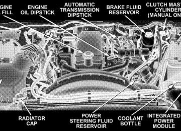
ENGINE COMPARTMENT — 6.7L DIESEL ENGINE
ONBOARD DIAGNOSTIC SYSTEM (OBD II) Vehicles equipped with California emissions controls have a sophisticated onboard diagnostic system called OBDII. This system monitors the performance of the emissions, engine, and automatic transmission control systems. When these systems are operating properly, your vehicle will provide excellent performance and fuel economy, as well as engine emissions well within current government regulations. If any of these systems require service, the OBD II system will turn on the “Malfunction Indicator Light.” It will also store diagnostic codes and other information to assist your service technician in making repairs. Al- though your vehicle will usually be driveable and not need towing, see your dealer for service as soon as possible.
MAINTAINING YOUR VEHICLE 409
CAUTION!
Prolonged driving with the “Malfunction Indicator Light” on could cause further damage to the emission control system. It could also affect fuel economy and driveability. The vehicle must be serviced before any emissions tests can be performed. If the “Malfunction Indicator Light” is flashing, severe catalytic converter damage and power loss will soon occur. Immediate service is required.
REPLACEMENT PARTS Use of genuine Mopart parts for normal/scheduled maintenance and repairs is highly recommended to en- sure the designed performance. Damage or failures caused by the use of non-Mopart parts for maintenance and repairs will not be covered by the manufacturer’s warranty.
410 MAINTAINING YOUR VEHICLE
ENGINE DATA PLATE Use the information from the engine data plate when discussing service or sourcing parts for your engine. The engine data plate is located on the intake side of the breather cover.
AUTHORIZED DEALER SERVICE Your authorized dealer has the qualified service person- nel, special tools and equipment to perform all service operations in an expert manner. Service manuals are available which include detailed service information for your vehicle. Refer to these manuals before attempting any procedure yourself. NOTE: systems can result against you.
Intentional tampering with emissions control in civil penalties being assessed
WARNING!
You can be badly injured working on or around a motor vehicle. Do only that service work for which you have the knowledge and the proper equipment. If you have any doubt about your ability to perform a service job, take your vehicle to a competent mechanic.
SERVICE INFORMATION Mopart Fluids, Lubricants and Parts are available from your authorized dealer and will help you keep your vehicle operating at its best. Your authorized dealer also has the qualified service personnel, special tools and equipment to perform all service operations in an expert manner. Service manuals are available which include detailed service infor- mation for your vehicle. Refer to these manuals before attempting any procedure yourself. See Service Publications information at the back of this manual.
CAUTION!
To maintain your vehicle safely follow these guide- lines: † Watch your vehicle’s mileage and check your Maintenance Schedules regularly for required ser- vicing. Excessive wear or damage to certain vehicle components can result if required services are not performed. † If you have your vehicle undercoated, inspect for undercoating material on the propeller shafts. Such material could cause the shafts to become unbalanced and result in drivetrain vibrations. Remove any undercoating with solvent. † If you have your vehicle undercoated, make sure no undercoating material is sprayed on the ex- haust system or components of the seat belt system.
MAINTAINING YOUR VEHICLE 411
It is not possible for the manufacturer and NOTE: Cummins, Inct. to anticipate every possible circumstance that can involve a potential hazard.
412 MAINTAINING YOUR VEHICLE
WARNING!
WARNING!
To maintain your vehicle safely and avoid personal injury, follow these guidelines: † Never spray or pour diesel fuel, flammable liquid or starting fluids (ether) into the air cleaner assembly, air intake piping or turbocharger inlet in an attempt to start the vehicle, unintended engine acceleration may occur. † Do not use alcohol or gasoline as a fuel blending agent. They can be unstable under certain conditions and be hazardous or explosive when mixed with diesel fuel. † If an engine has been operating and the coolant is hot, allow the engine to cool before you slowly loosen the filler cap and relieve the pressure from the cooling system. † To avoid burns, remember that the engine components will stay hot † Do not use gasoline or other flammable materials to clean parts. † Relieve all pressure in the fuel, oil and cooling systems before any lines, fittings or related items are removed or disconnected. Be alert for possible pressure when disconnecting any device from a system that utilizes pressure. Do not check for pressure leaks with your hand. High pressure oil or fuel can cause personal injury. † Important: All maintenance other than that listed in this manual, as well as some procedures listed here, MUST be performed by your authorized dealer. Your authorized dealer has been trained and has the necessary parts to maintain your engine.
Always use approved cleaning solvents.
after the engine is shut off.
Do not open the high pressure fuel system with the engine running. Engine operation causes high fuel pressure. High pressure fuel spray can cause serious injury or death.
MAINTENANCE PROCEDURES The pages that follow contain the required maintenance services determined by the engineers who designed your vehicle. Besides the maintenance items for which there are fixed maintenance intervals, there are other items that should operate satisfactorily without periodic maintenance. However, if a malfunction of these items does occur, it could adversely affect the engine or vehicle performance. These items should be inspected if a malfunction is observed or suspected.
Engine Oil
Checking Oil Level To assure proper lubrication of your vehicle’s engine, the engine oil must be maintained at the correct level. Check the oil level at regular intervals. The best time to check the oil level is before starting the engine after it has been parked overnight. When checking oil after operating the engine, first ensure the engine is at full operating tem- perature, then wait at least 30 minutes after engine shutdown to check the oil. Checking the vehicle while it’s on level ground will also improve the accuracy of the oil level readings. Add oil only when the level on the dipstick is below the “ADD” mark. The total capacity from the low mark to the high mark is 2 quarts (1.9 liters).
MAINTAINING YOUR VEHICLE 413
CAUTION!
Overfilling or underfilling the crankcase will cause oil aeration or loss of oil pressure. This could damage your engine.
414 MAINTAINING YOUR VEHICLE
Never operate the engine with oil level below the “ADD” mark or above the upper “SAFE” mark. Change Engine Oil (6.7L Diesel Engine) Follow the 6.7L Diesel Maintenance Schedule for recom- mended engine oil change intervals. Engine Oil Selection (6.7L Diesel Engines) For best performance and maximum protection under all types of operating conditions, the manufacturer only recommends engine oils that are API CJ-4 certified and meet the requirements of DaimlerChrysler. Use Mopart or an equivalent oil meeting DaimlerChrysler Material Standards MS-10902. Products meeting Cumminst CES 20081 may also be used. The identification of these engine oils are typically located on the back of the oil container.
American Petroleum Institute (API) Engine Oil Identification Symbol
This symbol means that the oil has been certified by the American Petro- leum Institute (API). The manufacture only recommends API CJ-4 certified engine oils.
Oils with a high ash content may produce deposits on valves that can progress to guttering and valve burning. A maximum sulfated ash content of 1.00 mass % is recommended for all oil used in the engine. The same oil change interval is to be followed for synthetic oil as for petroleum based oil. Also, synthetic oil must meet the same performance specifications as petro- leum oil.
SAE
15W-40
Engine Oil
Engine Oil Viscosity (SAE Grade) Use that meets DaimlerChrysler Materials Standard MS-10902 and the API CJ-4 engine oil category. Engine oil not designated by the DaimlerChrysler or Cumminst Material Standards and API CJ-4 should not be used, engine and exhaust system durability may be compromised. For lower temperature operation SAE 5W-40 engine oils may be used. These oils must meet the same requirements as stated previously. The engine oil filler cap also shows the recommended engine oil viscos- ity for your engine. For information on engine oil filler cap location, refer to the “Engine Compartment” illustra- tion in this section.
MAINTAINING YOUR VEHICLE 415
Synthetic Engine Oils You may use synthetic engine oils provided the recom- mended oil quality requirements are met, and the recom- mended maintenance intervals for oil and filter changes are followed. Materials Added to Engine Oil The manufacturer strongly recommends against the ad- dition of any additives (other than leak detection dyes or lube odorants) to the engine oil. Engine oil is an engi- neered product and it’s performance may be impaired by supplemental additives. NOTE: The manufacturer offers a lube odorant (Mopart Diesel Fresh) for diesel engines crankcases. The lube odorant is recommended by the manufacturer to reduce the sulfur smell that may occur during engine idling.
416 MAINTAINING YOUR VEHICLE
Engine Oil Filter Refer to Fluids, Lubricants and Genuine Parts for the correct part number. The engine oil filter should be changed at every engine oil change. Engine Oil And Filter — Change Operate the engine until the coolant temperature reaches 140°F (60°C). Shut the engine OFF. Remove the oil drain plug. Use a container that can hold at least 12 quarts (11.3
Liters) to hold the used oil. Always check the condition of the used oil. This can give you an indication of some engine problems that might exist. † Thin, black oil indicates fuel dilution. † Milky discoloration indicates coolant dilution.Clean the area around the oil filter base. Remove the filter from the underside of the vehicle using a cap style oil filter wrench. Clean the gasket surface of the filter mount. The filter gasket can stick on the filter mount. Make sure it is removed. Change the engine oil filter with every engine oil change. Only a high quality Mopart filter should be used to assure most efficient service.
CAUTION!
The filtering medium of other aftermarket filters may disintegrate. Debris from failed filters may plug the piston oil cooling nozzles, resulting in scuffed pistons and engine failure.
CAUTION!
Fill the oil filter element with clean oil before instal- lation. Use the same type oil that will be used in the engine. When filling the oil filter, prevent foreign material from falling into the filter. Severe engine damage may occur.
Apply a light film of lubricating oil to the sealing surface of the filter gasket before installing the filter.
CAUTION!
Overtightening may distort the threads or damage the filter element seal.
MAINTAINING YOUR VEHICLE 417
Install the filter as specified by the filter manufacturer. Turn the filter 3/4 to one full turn after making contact with the gasket. Check the condition of the threads and sealing surface on the oil pan and drain plug. Install the drain plug and sealing washer and tighten to 37 ft-lbs. (50 N·m). Use only high-quality multi-grade lubricating oil in your Cumminst Diesel Engine. Choose the correct oil for your operating conditions as outlined in the Selection of Engine Oil. Cumminst Turbo Diesel Fill the engine with the correct grade of new oil. The engine capacity is 11 quarts (10.4 liters) in the crankcase and 1 quart (.95 liter) in the lubricating oil filter.
418 MAINTAINING YOUR VEHICLE
Start the engine and operate it at idle for several minutes. Check for leaks at the lubricating oil filter and oil pan drain plug. Run the engine until it has reached operating tempera- ture, stop the engine. Wait approximately 15 minutes to let the oil in the upper parts of the engine drain back to the pan. Check the oil level again. Add oil as necessary to bring the level to the “SAFE” mark on the dipstick. Disposing Of Used Engine Oil And Filter Care should be taken in disposing of used engine oil and oil filters from your vehicle. Used oil and oil filters, indiscriminately discarded, can present a problem to the environment. Contact your authorized dealer, service station, or governmental agency for advice on how and where used oil and oil filters can be safely discarded in your area.
Drive Belt
able.
Inspection Check the belt for intersecting cracks. † Transverse (across the belt width) cracks are accept- † Longitudinal (direction of belt length) cracks that intersect with transverse cracks are NOT acceptable. Replace the belt if it has unacceptable cracks, is frayed or has pieces of material missing. The engine speed sensor, located near the damper, should be inspected for damage if a belt is frayed.
Engine Air Cleaner Filter (6.7L Diesel Engines)
CAUTION!
All air entering the engine intake must be filtered. The abrasive particles in unfiltered air will cause rapid wear to engine components.
The condition of the air cleaner filter is monitored by the Engine Control Module. The Electronic Vehicle Informa- tion Center (EVIC) will display SERVICE AIR FILTER when service is required. Do not remove the top of the air filter housing to inspect the filter element on your diesel engine under normal operating conditions. The EVIC message SERVICE AIR FILTER could be dis- played periodically. This is because engine air flow requirements change based on driving conditions. As the
MAINTAINING YOUR VEHICLE 419
filter becomes more restrictive and air flow requirements increase the EVIC message SERVICE AIR FILTER will be displayed. The message may not be displayed in subse- quent drive cycles if the same conditions are not met. The air filter element should be replaced within 250 miles from the first time this message is displayed to ensure proper engine operation during all driving conditions. The air filter housing on your vehicle may also come equipped with a Filter Minder™. This is an air flow restriction gauge that will indicate when the filter ele- ment needs to be replaced.
CAUTION!
Driving with a restricted air filter can cause engine damage.
420 MAINTAINING YOUR VEHICLE
If the vehicle experiences a sudden loss of engine power when being driven in heavy snow, rain or when plowing snow, and the EVIC message center states SERVICE AIR FILTER or the Filter Minder™ (if equipped) is showing a plugged filter, then visually inspect the air filter for snow/ice build up or extreme water saturation. If the air filter is not damaged, remove all snow/ice and reinstall air filter. If the air filter is damaged, replace filter element. NOTE: The air filter housing contains a Mass Air Flow sensor. This sensor is critical to proper engine operation and component longevity. Any damage or modification to this sensor could result in major engine and/or exhaust aftertreatment damage. This includes the use of non-approved air filters. Use only Mopart approved air filters or equivalent.
A visual inspection of the air cleaner filter element is never recommended under normal circumstances. A badly restricted element may appear clean while a soiled element may be quite effective in filtering particles without restricting air flow. Rely on the Engine Control Module or the Filter Minder™ (if equipped), to deter- mine when a filter change is necessary.
The clear plastic housing on the Filter Minder™ (If Equipped), allows you to view the amount of air pressure drop across the filter element. It consists of a diaphragm and a calibrated spring sealed inside the plastic housing. As the air cleaner filter becomes clogged and air pressure drop across the filter element increases, a yellow disc travels along a graduated scale on the side of the Filter Minder™. The yellow disc will always show the greatest restriction experienced by the filter element. When the disc reaches the red zone, the filter element may need to be replaced. There is no other time or mileage interval for changing the air cleaner filter element. After a new filter element is inserted, press the rubber button on the top of the Filter Minder™ (if equipped). This action will reset the yellow disc to the clean position.
MAINTAINING YOUR VEHICLE 421
CAUTION!
When using an engine cleaner or a degreaser, be sure to wrap and tape the Filter Minder™ to protect the plastic housing from damage and discoloration.
CAUTION!
Many aftermarket performance air filter elements do not adequately filter the air entering the engine. Use of such filters can severely damage your engine.
422 MAINTAINING YOUR VEHICLE
Draining Fuel/Water Separator Filter (6.7L Diesel Engine)
CAUTION!
Do not drain the fuel/water separator filter when the engine is running.
CAUTION!
Do not prefill the fuel filter when installing a new fuel filter. There is a possibility that debris could be introduced into the fuel filter during this action. It is best to install the filter dry and allow the in-tank lift pump to prime the fuel system.
NOTE: The fuel filter and water separator assembly is located on the driver’s side of the engine. The best access to the water drain valve is through the driver’s side wheel well. If water is detected in the water separator while NOTE: the engine is running or while the key is in the on position, the WATER IN FUEL LIGHT will illuminate and an audible chime will be heard five times. At this point you should stop the engine and drain the water from the separator.
If the WATER IN FUEL LIGHT comes on and a single chime is heard while you are driving, or with the key in the ON position, there may be a problem with your water separator wiring or sensor. See your authorized dealer for service. Upon proper draining of the water from the fuel filter, the WATER IN FUEL LIGHT will remain illuminated for approximately 10 seconds. If the water was drained while the engine was running, the water in fuel light may remain on for approximately three minutes. NOTE: Care should be taken in disposing of used fluids from your vehicle. Used fluids, indiscriminately dis- carded, can present a problem to the environment. Con- tact your local authorized dealer, service station, or government agency for advice on recycling programs and for where used fluids and filters can be properly disposed of in your area.
MAINTAINING YOUR VEHICLE 423
Drain a small amount from the fuel/water separator filter monthly or when the WATER IN FUEL LIGHT is on. Turn the drain valve located on the bottom of the filter counterclockwise and allow any accumulated water to drain into an approved container. Leave the drain valve open until all water and contaminants have been removed. Close the drain valve by turning it clockwise when clean fuel is visible. NOTE: The Fuel / Water separator drain valve is located on the bottom of the fuel filter housing. If more than a couple ounces of fuel has been drained, follow the directions below for “Priming if the engine has run out of fuel.”
424 MAINTAINING YOUR VEHICLE
WARNING!
Do not open the high pressure fuel system with the engine running. Engine operation causes high fuel pressure. High pressure fuel spray can cause serious injury or death.
Priming if the engine has run out of fuel 1. Add a substantial quantity of fuel to the tank, approxi- mately 5 to 10 gallons (19L to 38L). 2. Crank the engine for one to two seconds. If the engine does not start, then release the key or starter button back to the RUN position (do not turn the key back to the OFF position). The electric fuel transfer pump will continue to run and purge air from the system for about 25 seconds. After 25 seconds, attempt to start the engine again.
3. Start the engine using the normal starting procedure. 4. Repeat the procedure if the engine does not start.
CAUTION!
Do not engage the starter motor for more than 15
seconds at a time. Allow two minutes between the cranking intervals.NOTE: The engine may run rough until the air is forced from all the fuel lines.
CAUTION!
Diesel fuel will damage black top paving surfaces. Drain the filter into an appropriate container.
WARNING!
Do not use alcohol or gasoline as a fuel blending agent. They can be unstable under certain conditions and be hazardous or explosive when mixed with diesel fuel.
CAUTION!
Due to lack of lubricants in alcohol or gasoline, the use of these fuels can cause damage to the fuel system.
NOTE: A maximum blend of 5% biodiesel, meeting ASTM specification D-6751 may be used with your Cumminst Diesel equipped vehicle. Use of biodiesel
MAINTAINING YOUR VEHICLE 425
mixture in excess of 5% can negatively impact the on- engine fuel filter’s ability to separate water from the fuel, resulting in high pressure fuel system corrosion or dam- age. NOTE: As sufficient testing has not been completed, ethanol blends are not recommended or approved for use with your Cumminst Diesel equipped vehicle. In addition, commercially available fuel addi- NOTE: tives are not necessary for the proper operation of your Cumminst Diesel equipped vehicle. Intervention Regeneration Strategy – EVIC Message Process Flow (Catalyst Full Message) (6.7L Diesel Engines Only) Your new Cummins 6.7L diesel meets all EPA Heavy Duty Diesel Engine Emissions Standards, resulting in the lowest emitting diesel engine ever produced.
426 MAINTAINING YOUR VEHICLE
To achieve these emission standards, your vehicle is equipped with a state of the art engine and exhaust system. The engine and exhaust aftertreatment system work together to achieve the EPA Heavy Duty Diesel Engine Emissions Standards. These systems are seam- lessly integrated into your vehicle and managed by the Cumminst 6.7L engine Powertrain Control Module (PCM). The PCM manages engine combustion to allow the exhaust system’s catalyst to trap and burn Particulate Matter (PM) pollutants, with no input or interaction on your part. Additionally, the overhead console in your vehicle has the ability to alert you to additional maintenance re- quired on your truck or engine. Refer to the following messages that may be displayed on your Electronic Vehicle Information Center (EVIC):
WARNING!
A hot exhaust system can start a fire if you park over materials that can burn. Such materials might be grass or leaves coming into contact with your exhaust system. Do not park or operate your vehicle in areas where your exhaust system can contact anything that can burn.
Perform Service The 6.7L Cumminst engine utilizes a Closed Crankcase Ventilation (CCV) system, EGR valve and an EGR cooler. This system filters and recycles gasses produced in the crankcase during the normal combustion process. “Per- form Service” will be displayed on the overhead console of your vehicle if the CCV filter, EGR valve and EGR cooler are due for required maintenance. The CCV filter is
located on the top of the engine valve cover. For addi- tional information, see your local authorized dealer. Catalyst Full See Owner Manual “Catalyst Full See Owner Manual” will be displayed on the overhead console of your vehicle if the exhaust particulate filter reaches 80% of its maximum storage capacity. Under conditions of exclusive short duration and low speed driving cycles, your Cumminst engine and exhaust aftertreatment system may never reach the conditions required to remove the trapped PM. If this occurs, “Catalyst Full See Owner Manual” will be dis- played on the overhead console in your vehicle. If this message is displayed you will hear one chime to assist in alerting you of this condition. Catalyst Stat::::::::::80% Catalyst Stat::::::::::80% will replace the message “Catalyst Full See Owner Manual” after it is displayed for one minute. The engine Powertrain Control Module (PCM)
MAINTAINING YOUR VEHICLE 427
will continue to monitor the amount of particulate matter trapped in the particulate filter. This message indicates the percentage of the particulate filter capacity that has been used. By simply driving your vehicle at highway speeds for as little as 45 minutes you can remedy the condition in the particulate filter system and allow your Cumminst en- gine and exhaust aftertreatment system to remove the trapped PM and restore the system to normal operating condition. Catalyst Stat:::::::::::80%, 90%, 99% Catalyst Stat:::::::::::80%, 90%, 99% If you are unable to drive your vehicle under these conditions for an ex- tended period of time after the initial warning notifica- tion, the Engine PCM will continue to monitor the particulate filter and will display the progression of particulate filter usage (80, 90, 99%) on the EVIC message center.
428 MAINTAINING YOUR VEHICLE
CATALYST FULL SERVICE REQD If the particulate filter reaches 99% of its capacity, the overhead console in your vehicle will chime twice and display the message CATALYST FULL SERVICE REQD. At this point the engine PCM will register a fault code, the instrument panel will display a MIL light and the engine PCM will derate the truck, reducing its horse- power and torque output. The PCM derates the engine in order to limit the likeli- hood of permanent damage to the aftertreatment system. If this condition is not corrected and a dealer service is not performed, extensive exhaust aftertreatment damage can occur. In order to correct this condition it will be necessary to have the truck serviced by your local authorized dealer.
Maintenance Free Batteries The top of the maintenance free batteries are perma- nently sealed. You will never have to add water, nor is periodic maintenance required. NOTE: Replacement batteries should both be of equal capacity to prevent damage to the vehicle’s charging system.
WARNING!
† Battery fluid is a corrosive acid solution and can burn or even blind you. Don’t allow battery fluid to contact your eyes, skin or clothing. Don’t lean over a battery when attaching clamps. If acid splashes in eyes or on skin, flush the area imme- diately with large amounts of water. † Battery gas is flammable and explosive. Keep flame or sparks away from the battery. Don’t use a booster battery or any other booster source with an output greater than 12 volts. Don’t allow cable clamps to touch each other. † Battery posts, terminals and related accessories contain lead and lead compounds. Wash hands after handling.
MAINTAINING YOUR VEHICLE 429
CAUTION!
† It is essential when replacing the cables on the battery that the positive cable is attached to the positive post and the negative cable is attached to the negative post. Battery posts are marked (+) positive and (-) negative and identified on the battery case. † If a fast charger is used while the battery is in vehicle, disconnect both vehicle battery cables before connecting the charger to battery. Do not use a fast charger to provide starting voltage.
430 MAINTAINING YOUR VEHICLE
Battery Blanket Usage A battery loses 60% of its cranking power as the battery temperature decreases to 0°F (-18°C). For the same de- crease in temperature, the engine requires twice as much power to crank at the same RPM. The use of 120 VAC powered battery blankets will greatly increase starting capability at low temperatures. Suitable battery blankets are available from your authorized Mopart dealer. Air Conditioner Maintenance For best possible performance, your air conditioner should be checked and serviced by an authorized dealer at the start of each warm season. This service should include cleaning of the condenser fins and a performance test. Drive belt tension should also be checked at this time.
WARNING!
† Use only refrigerants and compressor lubricants approved by the manufacturer for your air condi- tioning system. Some unapproved refrigerants are flammable and can explode, injuring you. Other unapproved refrigerants or lubricants can cause the system to fail, requiring costly repairs. Refer to Section 3 of the Warranty Information book for further warranty information. † The air conditioning system contains refrigerant under high pressure. To avoid risk of personal injury or damage to the system, adding refrigerant or any repair requiring lines to be disconnected should be done by an experienced repairman.
NOTE: Use only manufacturer approved A/C System Sealers, Stop Leak Products, Seal Conditioners, Compres- sor Oil, or Refrigerants. Refrigerant Recovery and Recycling R-134a Air Conditioning Refrigerant is a hydrofluorocar- bon (HFC) that is endorsed by the Environmental Pro- tection Agency and is an ozone-saving product. How- ever, the manufacturer recommends that air conditioning service be performed by dealers or other service facilities using recovery and recycling equipment. Power Steering — Fluid Check Checking the power steering fluid level at a defined service interval is not required. The fluid should only be checked if a leak is suspected, abnormal noises are apparent, and/or the system is not functioning as antici- pated. Coordinate inspection efforts through a certified DaimlerChrysler Dealership.
MAINTAINING YOUR VEHICLE 431
WARNING!
Fluid level should be checked on a level surface and with the engine off to prevent injury from moving parts and to ensure accurate fluid level reading. Do not overfill. Use only manufacturer recommended power steering fluid.
If necessary, add fluid to restore to the proper indicated level. With a clean cloth, wipe any spilled fluid from all surfaces. Refer to Fluids, Lubricants, and Genuine Parts for correct fluid type. Front Suspension Ball Joints The ball joints originally supplied with the vehicle are permanently lubricated at the factory and do not require service. The ball joints and seals should be inspected whenever the vehicle is serviced for other reasons.
432 MAINTAINING YOUR VEHICLE
Steering Linkage — Inspection Whenever the vehicle is hoisted all steering linkage joints should be inspected for evidence of damage. If seals are damaged, parts should be replaced to prevent leakage or contamination of the grease. Front Prop Shaft Lubrication Lubricate the front driveshaft grease fitting at each oil change listed in the appropriate maintenance schedule for your vehicle. Use Mopart type MS-6560 (lithium based grease), or equivalent.
Front Driveshaft Grease Fitting
Front Axle Universal Drive Joints And Ball Joints The front axle universal joint and ball joints are perma- nently lubricated and do not require servicing.
Body Lubrication
Locks and all body pivot points, including such items as seat tracks, doors, liftgate, tailgate, sliding doors and hood hinges should be lubricated periodically to assure quiet, easy operation and to protect against rust and wear. Prior to the application of any lubricant, the parts concerned should be wiped clean to remove dust and grit. After lubricating, excess oil and grease should be removed. Particular attention should also be given to hood latching components to ensure proper function. When performing other underhood services, the hood latch, release mechanism and safety catch should be cleaned and lubricated. The external lock cylinders should be lubricated twice a year, preferably in the fall and spring. Apply a small amount of a high quality lubricant such as Mopart Lock Cylinder Lubricant di- rectly into the lock cylinder.
MAINTAINING YOUR VEHICLE 433
Windshield Wiper Blades The rubber edges of the wiper blades and the windshield should be cleaned periodically with a sponge or soft cloth and a mild nonabrasive cleaner. This will remove accu- mulations of salt or road film. Operation of the wipers on dry glass for long periods may cause deterioration of the wiper blades. Always use washer fluid when using the wipers to remove salt or dirt from a dry windshield. Avoid using the wiper blades to remove frost or ice from the windshield. Keep the blade rubber out of contact with petroleum products such as engine oil, gasoline, etc.
434 MAINTAINING YOUR VEHICLE
Windshield Washers The fluid reservoir is located under the hood and should be checked for fluid level at regular intervals. Fill the reservoir with windshield washer solvent only (not ra- diator antifreeze). When refilling the washer fluid reser- voir, take some washer fluid and apply it to a cloth or towel and wipe the wiper blades clean. This will help blade performance. To prevent freeze-up of your windshield washer system in cold weather, select a solution or mixture that meets or exceeds the temperature range of your climate. This rating information can be found on most washer fluid containers. The washer fluid reservoir will hold a full gallon of fluid when the Low Washer Fluid Light illuminates.
WARNING!
Commercially available windshield washer solvents are flammable. They could ignite and burn you. Care must be exercised when filling or working around the washer solution.
After the engine has warmed, operate the defroster for a few minutes to reduce the possibility of smearing or freezing the fluid on the cold windshield. Mopart All Weather Windshield Washer Solution, used with water as directed on the container, aids cleaning action, reduces the freezing point to avoid line clogging, and is not harmful to paint or trim.
Exhaust System The best protection against carbon monoxide entry into the vehicle body is a properly maintained engine exhaust system. Whenever a change is noticed in the sound of the exhaust system, when exhaust fumes can be detected inside the vehicle, or when the underside or rear of the vehicle is damaged, have a competent mechanic inspect the com- plete exhaust system and adjacent body areas for broken, damaged, deteriorated, or mispositioned parts. Open seams or loose connections could permit exhaust fumes to seep into the passenger compartment. In addition, inspect the exhaust system each time the vehicle is raised for lubrication or oil change. Replace as required.
MAINTAINING YOUR VEHICLE 435
WARNING!
Exhaust gases can injure or kill you. They contain carbon monoxide (CO) which is colorless and odor- less. Breathing it can make you unconscious and can eventually poison you. To avoid breathing CO, fol- low the preceding safety tips.
Exhaust System Rubber Isolator and Loop-Type Hanger — If Equipped Inspect surfaces whenever the vehicle is hoisted for rubber to metal separation or deep cracks. If, excessively deep localized cracks are present, or any part of the exhaust system abnormally contacts the underbody hard- ware, the isolator and/or hanger should be replaced.
436 MAINTAINING YOUR VEHICLE
Cooling System
WARNING!
You or others can be badly burned by hot coolant or steam from your radiator. If you see or hear steam coming from under the hood, don’t open the hood until the radiator has had time to cool. Never try to open a cooling system pressure cap when the radiator is hot.
Engine Coolant Checks Check the engine coolant (antifreeze) protection every 12
months (before the onset of freezing weather, where applicable). If coolant is dirty or rusty in appearance, the system should be drained, flushed and refilled with fresh coolant. Check the front of the A/C condenser for anyaccumulation of bugs, leaves, etc. If dirty, clean by gently spraying water from a garden hose vertically down the face of the condenser. Check the coolant recovery bottle tubing for brittle rub- ber, cracking, tears, cuts and tightness of the connection at the bottle and radiator. Inspect the entire system for leaks. Extremely cold ambient temperatures may require the addition of a “winter front” for effective operation of the cab heating/cooling system. Make certain that a percent- age of the radiator is exposed for adequate air flow through the charge air cooler and automatic transmission oil cooler. The percentage of opening must be increased with the increasing ambient air temperature and/or engine load. If the cooling fan can be heard cycling frequently, increase the size of the opening in the winter front.
Coolant bottle level check The coolant reserve system provides a quick visual method of determining that the coolant level is adequate. With the engine idling and warmed to the normal operating temperature, the level of the coolant on the coolant bottle should be between the fluid level marks. Check the coolant level whenever the hood is raised. The radiator normally remains completely full, so there is no longer a need to remove the coolant pressure cap except for checking coolant freeze point or replacement with new antifreeze coolant.
MAINTAINING YOUR VEHICLE 437
WARNING!
Never add coolant to the radiator when the engine is overheated. Do not loosen or remove pressure cap to cool overheated engine! The coolant is under pres- sure and severe scalding could result.
Cooling System — Drain, Flush and Refill At the intervals shown on the Maintenance Schedules, the system should be drained, flushed and refilled. See you authorized dealer for service.
438 MAINTAINING YOUR VEHICLE
CAUTION!
The manufacturer highly recommends that all cool- ing system service, maintenance, and repairs be per- formed by your local authorized dealer.
If the solution is dirty or contains a considerable amount of sediment, clean and flush with a reliable cooling system cleaner. Follow with a thorough rinsing to remove all deposits and chemicals. Properly dispose of old antifreeze solution. Selection Of Coolant Use only the manufacturer’s recommended coolant; for correct coolant type, refer to “Engine Coolant” under “Fluids, Lubricants and Genuine Parts” in this section.
CAUTION!
† Mixing of coolants other than specified HOAT engine coolants may result in engine damage and may decrease corrosion protection. If a non-HOAT coolant is introduced into the cooling system in an emergency, it should be replaced with the speci- fied coolant as soon as possible. † Do not use plain water alone or alcohol-base engine coolant (antifreeze) products. Do not use additional rust inhibitors or antirust products, as they may not be compatible with the radiator engine coolant and may plug the radiator. † This vehicle has not been designed for use with Propylene Glycol based coolants. Use of Propy- lene Glycol based coolants is not recommended.
Adding Coolant Your vehicle has been built with an improved engine coolant that allows extended maintenance intervals. This coolant can be used up to 5 Years or 100,000 miles (160
000 km) before replacement. To prevent reducing this extended maintenance period, it is important that you use the same coolant throughout the life of your vehicle. Please review these recommendations for using Hybrid Organic Additive Technology (HOAT) coolant. When adding coolant: † The manufacturerrecommends using Mopart Antifreeze/Coolant 5 Year/100,000 Mile Formula HOAT (Hybrid Organic Additive Technology). † Mix a minimum solution of 50% HOAT engine coolant and distilled water. Use higher concentrations (not to exceed 70%) if temperatures below -34°F (-37°C) are anticipated.
MAINTAINING YOUR VEHICLE 439
† Use only high purity water such as distilled or deion- ized water when mixing the water/engine coolant solution. The use of lower quality water will reduce the amount of corrosion protection in the engine cooling system.
Please note that it is the owner’s responsibility to main- tain the proper level of protection against freezing ac- cording to the temperatures occurring in the area where the vehicle is operated. NOTE: Mixing coolant types will decrease the life of the engine coolant and will require more frequent coolant changes. Cooling System Pressure Cap The cap must be fully tightened to prevent loss of coolant and to ensure that coolant will return to the radiator from the coolant recovery bottle.
440 MAINTAINING YOUR VEHICLE
The cap should be inspected and cleaned if there is any accumulation of foreign material on the sealing surfaces.
WARNING!
† The warning words “DO NOT OPEN HOT” on the cooling system pressure cap are a safety pre- caution. Never add coolant when the engine is overheated. Do not loosen or remove the cap to cool an overheated engine. Heat causes pressure to build up in the cooling system. To prevent scald- ing or injury, do not remove the pressure cap while the system is hot or under pressure. † Do not use a pressure cap other than the one specified for your vehicle. Personal injury or en- gine damage may result.
Disposal Of Used Engine Coolant Used ethylene glycol based engine coolant is a regulated substance requiring proper disposal. Check with your local authorities to determine the disposal rules for your community. Do not store ethylene glycol-based engine coolant in open containers or allow it to remain in puddles on the ground. Prevent ingestion by animals and children. If ingested by a child, contact a physician immediately. Clean up any ground spills immediately. Coolant Level The coolant bottle provides a quick visual method for determining that the coolant level is adequate. With the engine cold, the level of the coolant in the coolant recovery bottle should be between the ranges indicated on the bottle.
The radiator normally remains completely full, so there is no need to remove the radiator cap unless checking for coolant freeze point or replacing coolant. Advise your service attendant of this. As long as the engine operating temperature is satisfactory, the coolant bottle need only be checked once a month. When additional coolant is needed to maintain the proper level, it should be added to the coolant bottle. Do not overfill. Points To Remember NOTE: When the vehicle is stopped after a few miles (a few kilometers) of operation, you may observe vapor coming from the front of the engine compartment. This is normally a result of moisture from rain, snow, or high humidity accumulating on the radiator and being vapor- ized when the thermostat opens, allowing hot coolant to enter the radiator.
MAINTAINING YOUR VEHICLE 441
If an examination of your engine compartment shows no evidence of radiator or hose leaks, the vehicle may be safely driven. The vapor will soon dissipate. † Do not overfill the coolant recovery bottle. † Check coolant freeze point in the radiator and in the coolant recovery bottle. If antifreeze needs to be added, contents of coolant recovery bottle must also be protected against freezing. † If frequent coolant additions are required, or if the level in the coolant recovery bottle does not drop when the engine cools, the cooling system should be pres- sure tested for leaks. † Maintain coolant concentration at 50% HOAT engine coolant (minimum) and distilled water for proper corrosion protection of your engine which contains aluminum components.
442 MAINTAINING YOUR VEHICLE
† Make sure that the radiator and coolant recovery bottle overflow hoses are not kinked or obstructed. † Keep the front of the radiator clean. If your vehicle is equipped with air conditioning, keep the front of the condenser clean also. † Do not change the thermostat for summer or winter install operation. If replacement is ever necessary, ONLY the correct type thermostat. Other designs may result in unsatisfactory coolant performance, poor gas mileage, and increased emissions.
Fan
Inspection Check the fan for cracks and bent or broken blades. If any of these conditions exist, you must replace the fan. Make sure it is securely mounted.
NOTE: This service procedure must be performed by a trained service technician. Make arrangements with your authorized dealer for this inspection. Charge Air Cooler (Inter-Cooler) The charge air cooler is positioned between the radiator and the air conditioner condenser. Air enters the engine through the air cleaner and passes through the turbo- charger where it is pressurized. This pressurized air rapidly reaches high temperature. The air is then directed through a hose to the charge air cooler and through another hose to the intake manifold of the engine. The air entering the engine has been cooled by about 50 to 100
degrees Fahrenheit. This cooling process enables more efficient burning of fuel resulting in fewer emissions.To guarantee optimum performance of the system, keep the surfaces of the charge air cooler, condenser and radiator clean and free of debris. Periodically check the hoses leading to and from the charge air cooler for cracks or loose clamps resulting in loss of pressure and reduced engine performance. Hoses And Vacuum/Vapor Harnesses Inspect surfaces of hoses and nylon tubing for evidence of heat and mechanical damage. Hard or soft spots, brittle rubber, cracking, tears, cuts, abrasions, and exces- sive swelling indicate deterioration of the rubber. Pay particular attention to those hoses nearest to high heat sources such as the exhaust manifold. Inspect hose routing to be sure hoses do not come in contact with any heat source or moving component that may cause heat damage or mechanical wear.
MAINTAINING YOUR VEHICLE 443
Insure nylon tubing in these areas has not melted or collapsed. Inspect all hose connections such as clamps and cou- plings to make sure they are secure and no leaks are present. Components should be replaced immediately if there is any evidence of wear or damage that could cause failure. Brake System
Power Disc Brakes (Front and Rear) Disc brakes do not require adjustment; however, several hard stops during the break-in period are recommended to seat the linings and wear off any foreign material.
444 MAINTAINING YOUR VEHICLE
Brake Master Cylinder The fluid level of the master cylinder should be checked when performing under the hood service, or immedi- ately if the brake system warning lamp indicates system failure.
The brake master cylinder has a translucent plastic reservoir. On the outboard side of the reservoir there is a
“FULL” dot and an “ADD” dot. The fluid level must be kept within these two dots. Do not add fluid above the full mark because leakage may occur at the cap. With disc brakes, the fluid level can be expected to fall as the brake linings wear. However, an unexpected drop in fluid level may be caused by a leak and a system check should be conducted. For correct fluid type, refer to ”Brake Master Cylinder” under “Fluids, Lubricants and Genuine Parts” in this section.
WARNING!
Use of a brake fluid that may have a lower initial boiling point, or unidentified as to specification, may result in sudden brake failure during hard prolonged braking. You could have an accident.
WARNING!
Overfilling the brake fluid reservoir can result in spilling brake fluid on hot engine parts and the brake fluid catching fire.
Use only brake fluid that has been in a tightly closed container to avoid contamination from foreign matter or moisture.
CAUTION!
Do not allow a petroleum-base fluid to contaminate the brake fluid. Seal damage and loss of brake performance may result.
MAINTAINING YOUR VEHICLE 445
Brake Hoses Inspection should be performed whenever the brake system is serviced or at intervals specified. Inspect hy- draulic brake hoses for surface cracking, scuffing or worn spots. If there is any evidence of cracking, scuffing, or worn spots, the hose should be replaced immediately! Eventual deterioration of the hose can take place with possible burst failure. Clutch Linkage If the clutch pedal linkage begins to squeak or grunt, the clutch pedal pivot bushings should be lubricated. Refer to Fluids, Lubricants and Genuine Parts for the correct lubricant type. Multipurpose Grease, NLGI Grade 2 E.P. Clutch Hydraulic System The clutch hydraulic system is a sealed maintenance-free system. In the event of leakage or other malfunction, the system must be replaced.
446 MAINTAINING YOUR VEHICLE
Rear Axle And 4x4 Front Driving Axle Fluid Level For Model 9.25 Front Axles and 10.5”/11.5” Rear Axles refer to Fluids, Lubricants and Genuine Parts for the correct lubricant type. For normal service, periodic fluid level checks are not required. When the vehicle is ser- viced for other reasons, the exterior surfaces of the axle assembly should be inspected. When checking the fluid level, the vehicle should be in a level position. The fluid level should be 1/4” ± 1/4” (6.4
mm ± 6.4 mm) below the fill hole on the 9.25” Front Axle. The fluid level should be 3/4” ± 1/4” (19 mm ± 6.4 mm) below the fill hole on all 10.5” and 1/4” ± 1/4” (6.4 mm ± 6.4 mm) on 11.5” Rear Axles. Drain And Refill Follow the Maintenance Schedule for recommended fron and rear axle fluid change intervals.Lubricant Selection Refer to Fluids, Lubricants and Genuine Parts for the correct lubricant type. NOTE: The presence of water in the gear lubricant will result in corrosion and possible failure of differential components. Operation of the vehicle in water, as may be encountered in some off-highway types of service, will require draining and refilling the axle to avoid damage. Limited-Slip Differentials in vehicles equipped with 10.5”/11.5” Axles DO NOT REQUIRE any limited slip oil additive (friction modifiers). Transfer Case — If Equipped
Fluid Level Check This fluid level can be checked by removing the filler plug. The fluid level should be to the bottom edge of the filler plug hole with the vehicle in a level position.
Drain And Refill Follow the Maintenance Schedule for recommended transfer case fluid change intervals. Lubricant Selection Refer to Fluids, Lubricants and Genuine Parts for the correct lubricant type. Manual Transmission — If Equipped
Fluid Level Check This fluid level can be checked by removing the filler plug. If the level of the lubricant is more than 1/4” below the bottom of the filler hole while the vehicle is on level ground, enough lubricant should be added to bring the level to the bottom of the filler hole.
MAINTAINING YOUR VEHICLE 447
Lubricant Selection for 6-Speed Manual Transmission — If Equipped If it becomes necessary to add fluid or change the fluid, be sure to use the same lubricant or equivalent. Refer to Fluids, Lubricants and Genuine Parts for the correct lubricant type. Automatic Transmission
Selection Of Lubricant It is important that the proper lubricant is used in the transmission to assure optimum transmission perfor- mance. Use only manufacturer’s recommended transmis- sion fluid; refer to “Automatic Transmission” under “Fluids, Lubricants and Genuine Parts” in this section Refer to Fluids, Lubricants and Genuine Parts for correct fluid type. It is important that the transmission fluid be maintained at the prescribed level using the recom- mended fluid.
448 MAINTAINING YOUR VEHICLE
CAUTION!
Using a transmission fluid other than the manufac- turers recommended fluid may cause deterioration in transmission shift quality and/or torque converter shudder. Using a transmission fluid other than the manufacturers recommended fluid will result in more frequent fluid and filter changes. Refer to Fluids, Lubricants and Genuine Parts for correct fluid type.
Fluid Level Check If equipped with a dipstick, use the following procedure. If your vehicle has a capped dipstick tube, it is sealed and should not be tampered with. Your authorized dealer has the proper tools to ensure that the fluid level is set properly. The fluid level should be checked when the
engine is fully warmed up and the fluid in the transmis- sion is at normal operating temperature. Operation of the transmission with an improper fluid level will greatly reduce the life of the transmission and of the fluid. Check the fluid level whenever the vehicle is serviced. Procedure For Checking Fluid Level To properly check the automatic transmission fluid level, the following procedure must be used: 1. Operate the engine at idle speed and normal operating temperature. 2. The vehicle must be on level ground. 3. Fully apply the parking brake and press the brake pedal. 4. Place the gear selector momentarily in each gear position ending with the lever in PARK.
5. Remove the dipstick, wipe it clean and reinsert it until seated. 6. Remove the dipstick again and note the fluid level on both sides. The fluid level should be between the “HOT” (upper) reference holes on the dipstick at normal operat- ing temperature. Verify that a solid coating of oil is seen on both sides of the dipstick. If the fluid is low, add as required into the dipstick tube. Do not overfill. After adding any quantity of oil through the oil fill tube, wait a minimum of two minutes for the oil to fully drain into the transmission before rechecking the fluid level. If it is necessary to check the transmission below NOTE: the operating temperature, the fluid level should be