- 2009 Dodge RAM Diesel Owners Manuals
- Dodge RAM Diesel Owners Manuals
- 2010 Dodge RAM Diesel Owners Manuals
- Dodge RAM Diesel Owners Manuals
- 2005 Dodge RAM Diesel Owners Manuals
- Dodge RAM Diesel Owners Manuals
- 2006 Dodge RAM Diesel Owners Manuals
- Dodge RAM Diesel Owners Manuals
- 2008 Dodge RAM Diesel Owners Manuals
- Dodge RAM Diesel Owners Manuals
- 2004 Dodge RAM Diesel Owners Manuals
- Dodge RAM Diesel Owners Manuals
- 2007 Dodge RAM Diesel Owners Manuals
- Dodge RAM Diesel Owners Manuals
- Download PDF Manual
-
4WD LOCK and 4WD LOW positions can be used to lock the front and rear driveshafts together and force the front and rear wheels to rotate at the same speed. This is accomplished by rotating the 4WD Control Switch to the desired position - refer to “Shifting Procedure” in this section. The 4WD LOCK and 4WD LOW positions are designed for loose, slippery road surfaces only. Driving
300 STARTING AND OPERATING
in the 4WD LOCK and 4WD LOW positions on dry hard surfaced roads may cause increased tire wear and dam- age to the driveline components.
NOTE: The transfer case NEUTRAL position is selected by depressing the recessed button located on the lower left hand corner of the 4WD Control Switch. The transfer
case NEUTRAL position is to be used for recreational towing only. Refer to “Recreational Towing” in this section. Transfer Case Position Indicator Lights — Electronically Shifted Transfer Case Only Transfer case position indicator lights are located in the instrument cluster and indicate the current and desired transfer case selection. When you select a different trans- fer case position, the indicator lights will do the follow- ing: If All Shift Conditions Are Met: 1. The current position indicator light will turn OFF. 2. The selected position indicator light will flash until the transfer case completes the shift. 3. When the shift is complete, the indicator light for the selected position will stop flashing and remain ON.
If One or More Shift Conditions Are Not Met: 1. The indicator light for the current position will remain ON. 2. The newly selected position indicator light will con- tinue to flash. 3. The transfer case will not shift. NOTE: Before retrying a selection, make certain that all the necessary requirements for selecting a new transfer case position have been met. To retry the selection, turn the control knob back to the current position, wait five seconds, and retry selection. To find the shift require- ments, refer to the 9Shifting Procedure9 for your transfer case, located in this section. The “SERVICE 4WD” warning light monitors the electric shift 4WD system. If this light remains on after engine
STARTING AND OPERATING 301
start up or illuminates during driving, it means that the 4WD system is not functioning properly and that service is required.
WARNING!
Always engage the parking brake when powering down the vehicle if the (SERVICE 4WD( light is illuminated. Not engaging the parking brake may allow the vehicle to roll, which may cause personal injury.
NOTE: Do not attempt to make a shift while only the front or rear wheels are spinning, as this can cause damage to driveline components.
302 STARTING AND OPERATING
When operating your vehicle in 4WD LOW, the engine speed is approximately three times that of the 2WD or 4WD LOCK positions at a given road speed. Take care not to overspeed the engine and do not exceed 25 mph (40 km/h). Proper operation of 4-wheel drive vehicles depends on tires of equal size, type and circumference on each wheel. Any difference in tire size can cause damage to the transfer case. Because 4-wheel drive provides improved traction, there is a tendency to exceed safe turning and stopping speeds. Do not go faster than road conditions permit.
WARNING!
You or others could be injured if you leave the vehicle unattended with the transfer case in the NEUTRAL position without first fully engaging the parking brake. The transfer case NEUTRAL position disengages both the front and rear driveshafts from the powertrain and will allow the vehicle to move regardless of the transmission position. The parking brake should always be applied when the driver is not in the vehicle.
For additional information on the appropriate use of each transfer case mode position see the information below: 2WD Rear Wheel Drive High Range - Normal street and highway driving. Dry, hard surfaced roads.
4WD LOCK 4-Wheel Drive Lock Range - Locks the front and rear driveshafts together. Forces the front and rear wheels to rotate at the same speed. Additional traction for loose, slippery road surfaces only. 4WD LOW 4-Wheel Drive Low Range - Low speed 4-wheel drive. Locks the front and rear driveshafts together. Forces the front and rear wheels to rotate at the same speed. Additional traction and maximum pulling power for loose, slippery road surfaces only. Do not exceed 25 mph (40 km/h). Neutral - Disengages both the front and rear driveshafts from the powertrain. To be used for flat towing behind another vehicle. Refer to “Recreational Towing” in this section.
STARTING AND OPERATING 303
Shifting Procedure — Electronically Shifted Transfer Case
Transfer Case Switch
If any of the requirements to select a new NOTE: transfer case position have not been met, the transfer case will not shift. The indicator light for the previous position will remain ON and the newly selected position indicator
304 STARTING AND OPERATING
light will continue to flash until all the requirements for the selected position have been met. To retry a shift: return the control knob back to the original position, make certain all shift requirements have been met, wait five seconds and try the shift again. If all the requirements to select a new transfer NOTE: case position have been met, the current position indica- tor light will turn OFF, the selected position indicator light will flash until the transfer case completes the shift. When the shift is complete, the indicator light for the selected position will stop flashing and remain ON. 2WD, 4WD LOCK Rotate the 4WD control switch to the desired position. Shifts between 2WD and 4WD LOCK can be done with the vehicle stopped or in motion. With the vehicle in motion, the transfer case will engage/disengage faster if you momentarily release the accelerator pedal after turn- ing the control switch. If the vehicle is stopped, the
ignition key must be in the ON position with the engine either running or off. This shift cannot be completed if the key is in the ACC position. NOTE: The 4x4 system will not allow shifts between 2WD/4WD LOCK if the front and/or rear wheels are spinning (no traction). In this situation the selected position indicator light will flash and the original posi- tion indicator light will remain ON. At this time, reduce speed and stop spinning the wheels to complete the shift. 2WD or 4WD LOCK, 4WD LOW NOTE: When shifting into or out of 4WD LOW some gear noise may be heard. This noise is normal and is not detrimental to the vehicle or occupants. Shifting can be performed with the vehicle rolling 2 to 3
mph (3 to 5 km/h) or completely stopped. USE EITHER OF THE FOLLOWING PROCEDURES:Preferred Procedure 1. With engine running, slow vehicle to 2 to 3 mph (3 to 5 km/h). 2. Shift the transmission into NEUTRAL (depress clutch on manual transmissions). 3. While still rolling, rotate the transfer case control switch to the desired position. 4. After the desired position indicator light is ON (not flashing), shift transmission back into gear (release clutch on manual transmissions). Alternate Procedure 1. Bring the vehicle to complete stop. 2. With the key ON and the engine either OFF or running, shift the transmission into NEUTRAL (depress clutch on manual transmissions).
STARTING AND OPERATING 305
3. Rotate the transfer case control switch to the desired position. 4. After the desired position indicator light is ON (not flashing), shift transmission back into gear (release clutch on manual transmissions). If steps 1 or 2 of either the Preferred or Alternate NOTE: Procedure are not satisfied prior to attempting the shift then the desired position indicator light will flash con- tinuously while the original position indicator light is ON, until all requirements have been met. NOTE: The ignition key must be ON for a shift to take place and for the position indicator lights to be operable. If the key is not ON then the shift will not take place and no position indicator lights will be on or flashing. NOTE: than 21 days, refer to “Vehicle Storage” in section 7.
If your are leaving your vehicle stored for longer
306 STARTING AND OPERATING
LIMITED-SLIP DIFFERENTIAL — IF EQUIPPED The limited-slip differential provides additional traction on snow, ice, mud, sand and gravel, particularly when there is a difference between the traction characteristics of the surface under the right and left rear wheels. During normal driving and cornering, the limited-slip unit per- forms similarly to a conventional differential. On slip- pery surfaces, however, the differential delivers more of the driving effort to the rear wheel having the better traction. The limited-slip differential is especially helpful during slippery driving conditions. With both rear wheels on a slippery surface, a slight application of the accelerator will supply maximum traction. When starting with only one rear wheel on an excessively slippery surface, slight momentary application of the parking brake may be necessary to gain maximum traction.
WARNING!
On vehicles equipped with a limited-slip differen- tial, never run the engine with one rear wheel off the ground, since the vehicle may drive through the rear wheel remaining on the ground. You could lose control of the vehicle.
Care should be taken to avoid sudden accelerations when both rear wheels are on a slippery surface. This could cause both rear wheels to spin, and allow the vehicle to slide sideways on the crowned surface of a road or in a turn.
DRIVING ON SLIPPERY SURFACES When driving on wet or slushy roads, it is possible for a wedge of water to build up between the tire and road surface. This is known as hydroplaning and may cause partial or complete loss of vehicle control and stopping ability. To reduce this possibility, the following precau- tions should be observed: 1. Slow down during rainstorms or when roads are slushy. 2. Slow down if road has standing water or puddles. 3. Replace tires when tread wear indicators first become visible. 4. Keep tires properly inflated. 5. Maintain sufficient distance between your vehicle and the car in front to avoid a collision in a sudden stop.
STARTING AND OPERATING 307
DRIVING THROUGH WATER Driving through water more than a few inches/ centimeters deep will require extra caution to ensure safety and prevent damage to your vehicle. Flowing/Rising Water
WARNING!
Do not drive on, or cross, a road or a path where water is flowing and/or rising (as in storm run-off). Flowing water can wear away the road or path’s surface and cause your vehicle to sink into deeper water. Furthermore, flowing and/or rising water can carry your vehicle away swiftly. Failure to follow this warning may result in injuries that are serious or fatal to you, your passengers, and others around you.
308 STARTING AND OPERATING
Shallow Standing Water Although your vehicle is capable of driving through shallow standing water, consider the following Caution and Warning before doing so.
CAUTION!
† Always check the depth of the standing water before driving through it. Never drive through standing water that is deeper than the bottom of the tire rims mounted on the vehicle. † Determine the condition of the road or the path that is under water, and if there are any obstacles in the way, before driving through the standing water. † Do not exceed 5 mph (8 km/h) when driving through standing water. This will minimize wave effects.
CAUTION!
† Driving through standing water may cause dam- age to your vehicle’s drivetrain components. Al- ways inspect your vehicle’s fluids (i.e., engine oil, transmission, axle, etc.) for signs of contamination (i.e., fluid that is milky or foamy in appearance) after driving through standing water. Do not con- tinue to operate the vehicle if any fluid appears contaminated, as this may result in further dam- age. Such damage is not covered by the New Vehicle Limited Warranty. † Getting water inside your vehicle’s engine can cause it to lock up and stall out, and cause serious internal damage to the engine. Such damage is not covered by the New Vehicle Limited Warranty.
WARNING!
† Driving through standing water limits your vehi- cle’s traction capabilities. Do not exceed 5 mph (8
km/h) when driving through standing water. † Driving through standing water limits your vehi- cle’s braking capabilities, which increases stop- ping distances. Therefore, after driving through standing water, drive slowly and lightly press on the brake pedal several times to dry the brakes. † Getting water inside your vehicle’s engine can cause it to lock up and stall out, and leave you stranded. † Failure to follow these warnings may result in injuries that are serious or fatal to you, your passengers, and others around you.STARTING AND OPERATING 309
DRIVING OFF-ROAD Care should be taken when attempting to climb steep hills or driving diagonally across a hill or slope. If natural obstacles force you to travel diagonally up or down a hill, choose a mild angle and keep as little side tilt as possible. Keep the vehicle moving and make turns slowly and cautiously. If you must back down a hill, back straight down using REVERSE gear. Never back down in NEUTRAL, or diagonally across the hill. When driving over sand, mud, and other soft terrain, shift to low gear and drive steadily. Apply the accelerator slowly to avoid spinning the wheels. DO NOT REDUCE the tire pressures for this type of driving.
310 STARTING AND OPERATING
NOTE: After off-road usage, particularly in sand or mud, inspect the underside of the vehicle for accumu- lated dirt at the propeller shaft, axles, U-joints, brake rotors and calipers. Use a hose to clean off any accumulation of dirt or mud. Check the exhaust system and all exposed components for any sign of damage. If you experience unusual vibration after driving in mud, slush or similar conditions, check the wheels for im- pacted material. Impacted foreign material can cause a wheel imbalance. Removing the foreign material from the wheels will correct the situation.
PARKING BRAKE The foot-operated parking brake is positioned below the lower left corner of the instrument panel. To release the parking brake, pull the parking brake release handle. NOTE: The instrument cluster red brake warning light will come on and flash to indicate that the parking brake is applied. You must be sure that the parking brake is fully applied before leaving the vehicle.
STARTING AND OPERATING 311
WARNING!
† Always fully apply the parking brake when leav- ing your vehicle, or it may roll and cause damage or injury. Also be certain to leave an automatic transmission in PARK, a manual transmission in REVERSE or FIRST gear. Failure to do so may allow the vehicle to roll and cause damage or injury. † Never leave children alone in a vehicle. Leaving unattended children in a vehicle is dangerous for a number of reasons. A child or others could be seriously or fatally injured. Don’t leave the key in the ignition. A child could operate power win- dows, other controls, or move the vehicle. † Be sure the parking brake is fully disengaged before driving, failure to do so can lead to brake problems due to excessive heating of the rear brakes.
Parking Brake Release
Be sure the parking brake is firmly set when parked and the shift lever is in the PARK position. When parking on a hill you should apply the parking brake before placing the shift lever in PARK, otherwise the load on the transmission locking mechanism may make it difficult to move the shift lever out of PARK.
312 STARTING AND OPERATING
When parking on a hill, turn the front wheels toward the curb on a downhill grade and away from the curb on an uphill grade. The parking brake should always be applied whenever the driver is not in the vehicle.
BRAKE SYSTEM If power assist is lost for any reason (for example, repeated brake applications with the engine off), the brakes will still function. However, you will experience a substantial increase in braking effort to stop the vehicle. If either the front or rear hydraulic systems lose normal capability, the remaining system will still function with some loss of overall braking effectiveness. This will be evident by increased pedal travel during application, greater pedal force required to slow or stop, and activa- tion of the BRAKE warning light and the ABS light (if equipped) during brake use.
Brake Noise During normal operation of the brake system certain noises may be present from time to time. Occasional 9groan9 or 9squeal9 noises may occur during normal operation of the brake system which may not be indica- tive of a problem. These noises may be heard at any time the brakes are applied but may be more noticeable during the first few brake applications in the morning. Moisture, hot or cold temperature, dust, and or other debris may also contribute to the noise condition. Repeated or con- tinuous noises during braking may be an indication that the brake linings are worn and in need of replacement.
Four-Wheel Anti-Lock Brake System
WARNING!
Anti-Lock Brake Systems contain sophisticated elec- tronic equipment. It may be susceptible to interfer- ence caused by improperly installed or high output radio transmitting equipment. This interference can cause possible loss of anti-lock braking capability. Installation of such equipment should be performed by qualified professionals.
STARTING AND OPERATING 313
WARNING!
† The ABS cannot prevent accidents,
† Anti-lock Brake System (ABS) cannot prevent the natural laws of physics from acting on the vehicle, nor can it increase braking or steering efficiency beyond that afforded by the condition of the vehicle brakes and tires or the traction afforded. including those resulting from excessive speed in turns, following another vehicle too closely, or hydro- planing. Only a safe, attentive, and skillful driver can prevent accidents. † The capabilities of an ABS equipped vehicle must never be exploited in a reckless or dangerous manner which could jeopardize the user’s safety or the safety of others.
314 STARTING AND OPERATING
This Anti-lock Brake System is designed to aid the driver in maintaining vehicle control under adverse braking conditions. The system operates with a separate com- puter to modulate hydraulic pressure to prevent wheel lockup and help avoid skidding on slippery surfaces. The system’s pump motor runs during an ABS stop to provide regulated hydraulic pressure. The pump motor makes a low humming noise during operation. This is normal. When you are in a severe braking condition involving use of the Anti-lock Brake System, you will experience some pedal drop as the vehicle comes to a complete stop. This is the result of the system reverting to the base brake system and is normal. Engagement of the Anti-lock Brake System may be accompanied by a pulsing sensation in the brake pedal. You may also hear a clicking noise. These occurrences are normal, and indicate that the system is functioning.
ABS Warning Light The Anti-lock Brake System includes an amber warning light, located in the instrument cluster. When the light is illuminated, the Anti-lock Brake System is not function- ing. The system reverts to standard non-anti-lock brakes.
WARNING!
Pumping of the anti-lock brakes will diminish their effectiveness and may lead to an accident. Pumping makes the stopping distance longer. Just press firmly on your brake pedal when you need to slow down or stop.
STARTING AND OPERATING 315
WARNING!
Continued operation with reduced power steering assist could pose a safety risk to yourself and others. Service should be obtained as soon as possible.
CAUTION!
Prolonged operation of the steering system at the end of the steering wheel travel will increase the steering fluid temperature and should be avoided when pos- sible. Damage to the power steering pump may occur.
POWER STEERING The standard power steering system will give you good vehicle response and increased ease of maneuverability in tight spaces. The system will provide mechanical steering capability if power assist is lost. If for some reason the power assist is interrupted, it will still be possible to steer your vehicle. Under these condi- tions you will observe a substantial increase in steering effort, especially at very low vehicle speeds and during parking maneuvers. Increased noise levels at the end of the steering NOTE: wheel travel are considered normal and does not indicate that there is a problem with the power steering system. Upon initial start-up in cold weather, the power steering pump may make noise for a short period of time. This is due to the cold, thick fluid in the steering system. This noise should be considered normal, and does not in any way damage the steering system.
316 STARTING AND OPERATING
TIRE SAFETY INFORMATION
Tire Markings
NOTE: † P (Passenger)-Metric tire sizing is based on U.S. design standards. P-Metric tires have the letter “P” molded into the sidewall preceding the size designation. Ex- ample: P215/65R15 95H.
† European Metric tire sizing is based on European design standards. Tires designed to this standard have the tire size molded into the sidewall beginning with the section width. The letter 9P9 is absent from this tire size designation. Example: 215/65R15 96H. † LT (Light Truck)-Metric tire sizing is based on U.S. design standards. The size designation for LT-Metric tires is the same as for P-Metric tires except for the letters “LT” that are molded into the sidewall preced- ing the size designation. Example: LT235/85R16. † Temporary spare tires are high-pressure compact spares designed for temporary emergency use only. Tires designed to this standard have the letter “T” molded into the sidewall preceding the size designa- tion. Example: T145/80D18 103M. † High flotation tire sizing is based on U.S. design standards, and it begins with the tire diameter molded into the sidewall. Example: 31x10.5 R15 LT.
Tire Sizing Chart
Size Designation:
EXAMPLE:
P = Passenger Car tire size based on U.S. design standards (....blank....( = Passenger Car tire based on European design standards LT = Light Truck tire based on U.S. design standards T = Temporary spare tire 31 = Overall diameter in inches (in) 215 = Section width in millimeters (mm) 65 = Aspect ratio in percent (%).
— Ratio of section height to section width of tire
10.5 = Section width in inches (in) R = Construction code
— 9R9 means radial construction —9D9 means diagonal or bias construction
15 = Rim diameter in inches (in)
STARTING AND OPERATING 317
318 STARTING AND OPERATING
Service Description:
95 = Load Index
EXAMPLE:
— A numerical code associated with the maximum load a tire can carry
H = Speed Symbol
— A symbol indicating the range of speeds at which a tire can carry a load correspond- ing to its load index under certain operating conditions — The maximum speed corresponding to the speed symbol should only be achieved un- der specified operating conditions (i.e., tire pressure, vehicle loading, road conditions, and posted speed limits)
Load Identification:
(....blank....( = Absence of any text on the sidewall of the tire indicates a Standard Load (SL) Tire Extra Load (XL) = Extra load (or reinforced) tire Light Load = Light load tire C, D, E = Load range associated with the maximum load a tire can carry at a specified pressure
Maximum Load — Maximum load indicates the maximum load this tire is designed to carry Maximum Pressure — Maximum pressure indicates the maximum permissible cold tire inflation pressure for this tire
Tire Identification Number (TIN) The TIN may be found on one or both sides of the tire, however, the date code may only be on one side. Tires with white sidewalls will have the full TIN, including the date code,
located on the white sidewall side of the tire. Look for the TIN on the outboard side of black sidewall tires as mounted on the vehicle. If the TIN is not found on the outboard side, then you will find it on the inboard side of the tire.
STARTING AND OPERATING 319
EXAMPLE:
DOT MA L9 ABCD 0301
DOT = Department of Transportation
— This symbol certifies that the tire is in compliance with the U.S. Department of Transportation tire safety standards, and is approved for highway use
MA = Code representing the tire manufacturing location (two digits) L9 = Code representing the tire size (two digits) ABCD = Code used by the tire manufacturer (one to four digits) 03 = Number representing the week in which the tire was manufactured (two digits)
—03 means the 3rd week.
01 = Number representing the year in which the tire was manufactured (two digits)
—01 means the year 2001
— Prior to July 2000, tire manufacturers were only required to have one number to represent the year in which the tire was manufactured. Example: 031 could represent the 3rd week of 1981 or 1991320 STARTING AND OPERATING
Tire Loading and Tire Pressure
Tire Placard Location NOTE: The proper cold tire inflation pressure is listed on either the face of the driver’s door or the driver’s side B-Pillar.
Tire and Loading Information Placard
Tire And Loading Information Placard
This placard tells you important information about the: 1) number of people that can be carried in the vehicle 2) total weight your vehicle can carry 3) tire size designed for your vehicle 4) cold tire inflation pressures for the front, rear, and spare tires.
Tire Placard Location
Loading The vehicle maximum load on the tire must not exceed the load carrying capacity of the tire on your vehicle. You will not exceed the tire’s load carrying capacity if you adhere to the loading conditions, tire size, and cold tire inflation pressures specified on the Tire and Loading Information placard and in the “Vehicle Loading” section of this manual. NOTE: Under a maximum loaded vehicle condition, gross axle weight ratings (GAWRs) for the front and rear axles must not be exceeded. For further information on GAWRs, vehicle loading, and trailer towing, refer to “Vehicle Loading” in this section. To determine the maximum loading conditions of your vehicle, locate the statement “The combined weight of occupants and cargo should never exceed XXX kg or XXX lbs.” on the Tire and Loading Information placard. The
STARTING AND OPERATING 321
combined weight of occupants, cargo/luggage and trailer tongue weight (if applicable) should never exceed the weight referenced here. Steps for Determining Correct Load Limit 1. Locate the statement “The combined weight of occu- pants and cargo should never exceed XXX lbs or XXX kg” on your vehicle’s placard. 2. Determine the combined weight of the driver and passengers that will be riding in your vehicle. 3. Subtract the combined weight of the driver and pas- sengers from XXX kg or XXX lbs. 4. The resulting figure equals the available amount of cargo and luggage load capacity. For example, if “XXX” amount equals 1,400 lbs (635 kg) and there will be five 150 lb (68 kg) passengers in your vehicle, the amount of
322 STARTING AND OPERATING
available cargo and luggage load capacity is 650 lbs (295
kg) {(since 5 x 150 = 750, and 1400 – 750 = 650 lbs (295
kg)}. 5. Determine the combined weight of luggage and cargo being loaded on the vehicle. That weight may not safely exceed the available cargo and luggage load capacity calculated in Step 4. 6. If your vehicle will be towing a trailer, load from your trailer will be transferred to your vehicle. Consult this manual to determine how this reduces the available cargo and luggage load capacity of your vehicle.NOTE: The following table shows examples on how to calculate total load, cargo/luggage, and towing capaci- ties of your vehicle with varying seating configurations and number and size of occupants. This table is for illustration purposes only and may not be accurate for the seating and load carry capacity of your vehicle. NOTE: For the following example, the combined weight of occupants and cargo should never exceed 865 lbs (392
kg).STARTING AND OPERATING 323
324 STARTING AND OPERATING
WARNING!
1. Safety—
Overloading of your tires is dangerous. Overloading can cause tire failure, affect vehicle handling, and increase your stopping distance. Use tires of the recommended load capacity for your vehicle. Never overload them.
TIRES — GENERAL INFORMATION
Tire Pressure Proper tire inflation pressure is essential to the safe and satisfactory operation of your vehicle. Three primary areas are affected by improper tire pressure:
WARNING!
† Improperly inflated tires are dangerous and can cause accidents. † Under-inflation increases tire flexing and can result in tire failure. † Over-inflation reduces a tire’s ability to cushion shock. Objects on the road and chuckholes can cause damage that result in tire failure. † Unequal tire pressures can cause steering problems. You could lose control of your vehicle. † Over-inflated or under-inflated tires can affect vehicle handling and can fail suddenly, resulting in loss of vehicle control. † Unequal tire pressures from one side of the vehicle to the other can cause the vehicle to drift to the right or left. † Always drive with each tire inflated to the recom- mended cold tire inflation pressure.
2. Economy— Improper inflation pressures can cause uneven wear patterns to develop across the tire tread. These abnormal wear patterns will reduce tread life resulting in a need for earlier tire replacement. Under-inflation also increases tire rolling resistance and results in higher fuel consump- tion. 3. Ride Comfort and Vehicle Stability— Proper tire inflation contributes to a comfortable ride. Over-inflation produces a jarring and uncomfortable ride. Tire Inflation Pressures The proper cold tire inflation pressure is listed either on the face of the driver’s door or on the driver’s side “B” pillar. Some vehicles may have Supplemental Tire Pressure Information for vehicle loads that are less than the
STARTING AND OPERATING 325
maximum loaded vehicle condition. These pressure con- ditions will be found in the “Supplemental Tire Pressure Information” section of this manual.
Tire Placard Location
The pressure should be checked and adjusted as well as inspecting for signs of tire wear or visible damage at least once a month. Use a good quality pocket-type gauge to
326 STARTING AND OPERATING
check tire pressure. Do not make a visual judgement when determining proper inflation. Radial tires may look properly inflated even when they are under-inflated.
CAUTION!
After inspecting or adjusting the tire pressure, al- ways reinstall the valve stem cap (if equipped). This will prevent moisture and dirt from entering the valve stem, which could damage the valve stem.
Inflation pressures specified on the placard are always “cold tire inflation pressure.” Cold tire inflation pressure is defined as the tire pressure after the vehicle has not been driven for at least three hours, or driven less than 1
mi (1.6 km) after a three hour period. The cold tire inflation pressure must not exceed the maximum infla- tion pressure molded into the tire sidewall.Check tire pressures more often if subject to a wide range of outdoor temperatures, as tire pressures vary with temperature changes. Tire pressures change by approximately 1 psi (7 kPa) per 12°F (7°C) of air temperature change. Keep this in mind when checking tire pressure inside a garage, especially in the Winter. Example: If garage temperature = 68°F (20°C) and the outside temperature = 32°F (0°C) then the cold tire inflation pressure should be increased by 3 psi (21 kPa), which equals 1 psi (7 kPa) for every 12°F (7°C) for this outside temperature condition. Tire pressure may increase from 2 to 6 psi (13 to 40 kPa) during operation. DO NOT reduce this normal pressure build up or your tire pressure will be too low.
Tire Pressures for High Speed Operation The manufacturer advocates driving at safe speeds within posted speed limits. Where speed limits or condi- tions are such that the vehicle can be driven at high speeds, maintaining correct tire inflation pressure is very important. Increased tire pressure and reduced vehicle loading may be required for high-speed vehicle opera- tion. Refer to original equipment or an authorized tire dealer for recommended safe operating speeds, loading and cold tire inflation pressures.
WARNING!
High speed driving with your vehicle under maxi- mum load is dangerous. The added strain on your tires could cause them to fail. You could have a serious accident. Don’t drive a vehicle loaded to the maximum capacity at continuous speeds above 75
mph (120 km/h).STARTING AND OPERATING 327
Radial Ply Tires
WARNING!
Combining radial ply tires with other types of tires on your vehicle will cause your vehicle to handle poorly. The instability could cause an accident. Al- ways use radial ply tires in sets of four (or six, in case of trucks with dual rear wheels). Never combine them with other types of tires.
Cuts and punctures in radial tires are repairable only in the tread area because of sidewall flexing. Consult your authorized tire dealer for radial tire repairs.
328 STARTING AND OPERATING
Compact Spare Tire — If Equipped The compact spare is for temporary emergency use with radial tires. It is engineered to be used on your style vehicle only. Since this tire has limited tread life, the original tire should be repaired (or replaced) and rein- stalled at the first opportunity.
Do not install a wheel cover or attempt to mount a conventional tire on the compact spare wheel, since the wheel is designed specifically for the compact spare. Do not install more than one compact spare tire/wheel on the vehicle at any given time.
WARNING!
CAUTION!
Temporary use spare tires are for emergency use only. With these tires, do not drive more than 50 mph (80
km/h). Temporary use spare tires have limited tread life. When the tread is worn to the tread wear indicators, the temporary use spare tire needs to be replaced. Be sure to follow the warnings, which apply to your spare. Failure to do so could result in spare tire failure and loss of vehicle control.Because of the reduced ground clearance, do not take your vehicle through an automatic car wash with the compact spare installed. Damage to the vehicle may result.
Limited-Use Spare — If Equipped The limited-use spare tire is for temporary emergency use on your vehicle. This tire is identified by a limited- use spare tire warning label located on the limited-use spare tire and wheel assembly. This tire may look like the
original equipped tire on the front or rear axle of your vehicle, but it is not. Installation of this limited-use spare tire affects vehicle handling. Since it is not the same tire, replace (or repair) the original tire and reinstall on the vehicle at the first opportunity.
WARNING!
The limited-use spare tires are for emergency use only. Installation of this limited-use spare tire affects vehicle handling. With this tire, do not drive more than 50 mph (80 km/h). Keep inflated to the cold tire inflation pressure listed on either your tire placard or limited-use spare tire and wheel assembly. Replace (or repair) the original tire at the first opportunity and reinstall it on your vehicle. Failure to do so could result in loss of vehicle control.
STARTING AND OPERATING 329
Tire Spinning When stuck in mud, sand, snow, or ice conditions, do not spin your vehicle’s wheels faster than 30 mph (48 km/h) or for longer than 30 seconds continuously without stopping when you are stuck. For additional information, refer to “Freeing A Stuck Vehicle” in Section 6.
WARNING!
Fast spinning tires can be dangerous. Forces gener- ated by excessive wheel speeds may cause tire dam- age or failure. A tire could explode and injure some- one. Do not spin your vehicle’s wheels faster than 30
mph (48 km/h) or for more than 30 seconds continu- ously when you are stuck, and don’t let anyone near a spinning wheel, no matter what the speed.330 STARTING AND OPERATING
Tread Wear Indicators Tread wear indicators are in the original equipment tires to help you in determining when your tires should be replaced.
becomes 1/16 in (2 mm). When the tread is worn to the tread wear indicators, the tire should be replaced. Many states have laws requiring tire replacement at this point. Life of Tire The service life of a tire is dependent upon varying factors including, but not limited to: † Driving style † Tire pressure † Distance driven
These indicators are molded into the bottom of the tread grooves. They will appear as bands when the tread depth
WARNING!
Tires and the spare tire should be replaced after six years, regardless of the remaining tread. Failure to follow this warning can result in sudden tire failure. You could lose control and have an accident resulting in serious injury or death.
Keep dismounted tires in a cool, dry place with as little exposure to light as possible. Protect tires from contact with oil, grease, and gasoline.
STARTING AND OPERATING 331
Replacement Tires The tires on your new vehicle provide a balance of many characteristics. They should be inspected regularly for wear and correct cold tire inflation pressure. The manu- facturer strongly recommends that you use tires equiva- lent to the originals in size, quality and performance when replacement is needed. (Refer to the paragraph on “Tread Wear Indicators”). Refer to the “Tire and Loading Information” placard for the size designation of your tire. The service description and load identification will be found on the original equipment tire. Failure to use equivalent replacement tires may adversely affect the safety, handling, and ride of your vehicle. We recommend that you contact your original equipment or an autho- rized tire dealer with any questions you may have on tire specifications or capability.
332 STARTING AND OPERATING
WARNING!
† Do not use a tire, wheel size or rating other than that specified for your vehicle. Some combinations of unapproved tires and wheels may change suspension dimensions and performance characteristics, result- ing in changes to steering, handling, and braking of your vehicle. This can cause unpredictable handling and stress to steering and suspension components. You could lose control and have an accident resulting in serious injury or death. Use only the tire and wheel sizes with load ratings approved for your vehicle. † Never use a tire with a smaller load index or capacity, other than what was originally equipped on your vehicle. Using a tire with a smaller load index could result in tire overloading and failure. You could lose control and have an accident. † Failure to equip your vehicle with tires having ad- equate speed capability can result in sudden tire failure and loss of vehicle control.
CAUTION!
Replacing original tires with tires of a different size may result in false speedometer and odometer readings.
Alignment and Balance Poor suspension alignment may result in: † Fast tire wear. † Uneven tire wear, such as feathering and one-sided † Vehicle pull to right or left. Tires may also cause the vehicle to pull to the left or right. Alignment will not correct this condition. See your authorized dealer for proper diagnosis.
wear.
Improper alignment will not cause vehicle vibration. Vibration may be a result of tire and wheel out-of- balance. Proper balancing will reduce vibration and avoid tire cupping and spotty wear.
SUPPLEMENTAL TIRE PRESSURE INFORMATION — IF EQUIPPED A light load vehicle condition is defined as two passen- gers [150 lbs (68 kg) each] plus 200 lbs (91 kg) of cargo. Cold tire inflation pressures for a lightly loaded vehicle will be found on the face of the driver’s door.
TIRE CHAINS Use “Class U” chains on 2500/3500 Ram Trucks, or other traction aids that meet SAE Type “U” specifications. NOTE: Chains must be the proper size for the vehicle, as recommended by the chain manufacturer.
STARTING AND OPERATING 333
CAUTION!
To avoid damage to your vehicle, tires or chains, observe the following precautions: † Because of limited chain clearance between tires and other suspension components, it is important that only chains in good condition are used. Broken chains can cause serious vehicle damage. Stop the vehicle immediately if noise occurs that could suggest chain breakage. Remove the damaged parts of the chain before further use. † Install chains as tightly as possible and then retighten after driving about 1/2 mile (0.8 km). † Do not exceed 45 mph (72 km/h). † Drive cautiously and avoid severe turns and large bumps, † Do not install tire chains on front wheels of 4x2 vehicles. † Do not drive for a prolonged period on dry pavement. † Observe the tire chain manufacturer’s instructions on method of installation, operating speed, and conditions for usage. Always use the lower suggested operating speed of the chain manufac- turer than the speed recommended by the manufacturer.
especially with a loaded vehicle.
if different
334 STARTING AND OPERATING
These cautions apply to all chain traction devices, includ- ing link and cable (radial) chains. Tire chain use is permitted only on the rear tires of Ram 4X2 trucks. NOTE: The use of class “U” chains is permitted on the front and rear of 4X4, 2500 Ram Trucks with LT245/ 70R17E tires. NOTE: The use of class “U” chains is permitted on the front and rear of 4X4, 3500 Ram Trucks with Dual Rear Wheels and LT235/80R17E tires. NOTE: On 4X2 2500/3500 Ram Trucks, class “U” snow chains are permitted on the rear wheels only of vehicles equipped with LT245/70R17, LT265/70R17, and LT235/ 80R17 size tires.
NOTE: On 4X4 2500/3500 Single Rear Wheel (SRW) Ram Trucks, class “U” snow chains are permitted on the rear wheels only of vehicles equipped with LT265/70R17.
CAUTION!
Do not use tire chains on 4x4 Ram trucks equipped with P265/70R17, LT275/70R17 tires. There may not be adequate clearance for the chains and you are risking structural or body damage to your vehicle. Do not use tire chains on the 4X2 front wheels of 2500/3500 SRW (Single Rear Wheels) equipped with LT245/70R17, LT265/70R17 tires or 4X4 front tires of Ram Trucks equipped with LT265/70R17tires. There may not be adequate clearance for the chains and you are risking structural or body damage to your vehicle.
SNOW TIRES Snow tires should be of the same size and type construc- tion as the front tires. Consult the manufacturer of the snow tire to determine any maximum vehicle speed requirement associated with the tire. These tires should always be operated at the vehicle maximum capacity inflation pressures under any load condition. While studded tires improve performance on ice, skid and traction capability on wet or dry surfaces may be poorer than that of non-studded tires. Some states pro- hibit studded tires; local laws should be checked before using these tire types.
therefore,
STARTING AND OPERATING 335
TIRE ROTATION RECOMMENDATIONS Tires on the front and rear axles of vehicles operate at different loads and perform different steering, driving, and braking functions. For these reasons, they wear at unequal rates and develop irregular wear patterns. These effects can be reduced by timely rotation of tires. The benefits of rotation are especially worthwhile with ag- gressive tread designs such as those on ON/OFF Road type tires. Rotation will increase tread life, help to main- tain mud, snow, and wet traction levels, and contribute to a smooth, quiet ride.
336 STARTING AND OPERATING
Follow the recommended tire rotation frequency for your type of driving found in the “Maintenance Schedules” Section of this manual. More frequent rotation is permis- sible if desired. The reasons for any rapid or unusual wear should be corrected prior to rotation being per- formed.
NOTE: On Canadian vehicles only, if your vehicle is equipped with All-Season type tires on the front and ON/OFF Road type tires mounted on the rear, do not use a front-to-back rotation pattern. Instead, rotate your tires side-to-side at the recommended intervals.
Dual Rear Wheels
The tires used on dual wheel assemblies should be matched for wear to prevent overloading one tire in a set. To check if tires are even, lay a straight edge across all four tires. The straight edge should touch all the tires.
STARTING AND OPERATING 337
CAUTION!
3500 Dual Rear Tires have only one approved direc- tion of rotation. This is to accommodate the asym- metrical design (tread pattern) of the ON/OFF road tire and the use of Outline White Letter (OWL) tires. † When replacing a flat, the spare tire may have to be remounted on the rim, or installed at a different location, to maintain the correct placement of the tire on the wheel relative to the tire/wheel position on the truck. For example, if the spare is used to replace an outer rear tire it will have to be re- mounted on the rim so that the wheel is dished inward. That way the tread design of asymmetrical tires and the white writing of the OWL tires will maintain proper position.
338 STARTING AND OPERATING
TIRE PRESSURE MONITOR SYSTEM (TPMS) — IF EQUIPPED The Tire Pressure Monitoring System (TPMS) will warn the driver of a low tire pressure based on the vehicle recommended cold tire inflation placard pressure. The placard pressure is defined on the Tire and Loading Information label. The Tire and Loading Information label is located on the drivers side B-pillar. Vehicles equipped to be operated in either the “max load inflation pressure” condition described on the Tire and Loading Information label or the alternative “light load inflation pressure” condition described on the Supplemental Tire Pressure Information label, may also be equipped with a reset switch to choose the appropriate TPMS low pres- sure warning threshold levels based upon the vehicle load condition. The Supplemental Tire Pressure Informa- tion label is located on the rear face of the driver door. Operation of the “Light Load” reset switch is described later in this manual section.
The tire pressure will vary with temperature by approxi- mately 1 psi (6.9 kPa) for every 12°F (6.5°C). This means that when the outside temperature decreases, the tire pressure will decrease. Tire pressure should always be set based on cold inflation tire pressure. This is defined as the tire pressure after a vehicle has not been driven for more than 3 hours, or driven less than 1 mile after a 3
hour period. For information on how to properly inflate the vehicle’s tires, refer to ”Tire Pressure” under “Tires – General Information” in this section. The tire pressure will also increase as the vehicle is driven - this is normal and there should be no adjustment for this increased pressure. The TPM System will warn the driver of a low tire pressure if the tire pressure falls below the low pressure warning threshold for any reason, including low tem- perature effects, or natural pressure loss through the tire.The TPM System will continue to warn the driver of low tire pressure as long as the condition exists, and will not turn off until the tire pressure is at or above recom- mended cold placard pressure. Once the low tire pressure warning has been illuminated, the tire pressure must be increased to the recommended cold placard pressure in order for the TPMS warning lamp to be turned off. The system will automatically update and the TPMS warning lamp will extinguish once the updated tire pressures have been received. The vehicle may need to be driven for up to 10 minutes above 15 mph (25 km/h) to receive this information. As an example, assume your vehicle has a recommended cold tire inflation placard pressure (parked for more than 3 hours) of 35 psi (241 kPa). If the ambient temperature is 68°F (20°C) and the measured tire pressure is 30 psi (207
kPa), a temperature drop to 20°F (-7°C) will decrease the tire pressure to approximately 26 psi (179 kPa). This tire pressure is sufficiently low enough to turn ON the TireSTARTING AND OPERATING 339
Pressure Monitoring lamp. Driving the vehicle may cause the tire pressure to rise to approximately 30 psi (207 kPa), but the Tire Pressure Monitoring lamp will still be ON. In this situation, the Tire Pressure Monitoring lamp will turn OFF only after the tires have been inflated to the vehicle’s recommended cold tire placard pressure value.
CAUTION!
The TPMS has been optimized for the original equipment tires and wheels. TPMS pressures have been established for the tire size equipped on your vehicle. Undesirable system operation or sensor damage may result when using replacement equip- ment that is not of the same size, type, and/or style. After-market wheels can cause sensor damage. Do not use aftermarket tire sealants or balance beads if your vehicle is equipped with a TPMS, as damage to the sensors may result.
340 STARTING AND OPERATING
CAUTION!
After inspecting or adjusting the tire pressure always reinstall the valve stem cap. This will prevent mois- ture and dirt from entering the valve stem, which could damage the Tire Pressure Monitoring Sensor.
NOTE: † The TPMS is not intended to replace normal tire care and maintenance, nor to provide warning of a tire failure or condition. † The TPMS should not be used as a tire pressure gauge
while adjusting your tire pressure.
† Driving on a significantly under-inflated tire causes the tire to overheat and can lead to tire failure. Under-inflation also reduces fuel efficiency and tire tread life, and may affect the vehicle’s handling and stopping ability. † The TPMS is not a substitute for proper tire mainte- nance, and it is the driver’s responsibility to maintain correct tire pressure, even if under-inflation has not reached the level to trigger illumination of the “Tire Pressure Monitoring Telltale Light.” † Seasonal temperature changes will affect tire pressure, and the TPM system will monitor the actual tire pressure in the tire.
Tire Pressure Monitor System (TPMS) “Light Load” Reset Switch Description – If Equipped
WARNING!
Never operate your vehicle with the TPMS and tire pressures set to the Light Load Inflation Pressure settings if carrying more than two occupants (150 lbs each) plus 200 pounds of cargo. The vehicle “Light Load Definition” is found in the Supplemental Tire Pressure Information Label which is located on the rear face of the driver door. Failure to do so may cause you to lose control resulting in an accident, causing serious or fatal injury.
STARTING AND OPERATING 341
The TPMS “Light Load” reset switch will allow the driver to switch between the max load inflation pressure (cold) low pressure warning threshold and the light load infla- tion pressure (cold) low pressure warning threshold depending on the vehicle’s load condition. The Tire and Loading Information label defines the recommended front and rear cold tire inflation pressures for the vehicle when operating in the Max Load condition. A Supple- mental Tire Pressure Information label is also available defining Light Load tire inflation pressures when oper- ating in the Light Load condition. When the “Light Load” reset switch LED is ON, the TPMS is using the light load inflation pressure (cold) low inflation warning thresh- olds.
342 STARTING AND OPERATING
Light Load Reset Switch
“Light Load” Reset Switch Operation – If Equipped † This vehicle may have different recommended tire pressure values between the front and rear tires as shown in both the Tire Loading Information Label and the Supplemental Tire Pressure Information Label. It is also equipped to be driven with tire pressures appro- priate to either a Light Load condition or the vehicle Max Load condition. † The “Light Load” reset switch will allow the driver to change between the max load inflation pressure (cold) low pressure warning threshold and the light load inflation pressure (cold) low pressure warning thresh- old depending on the vehicle’s load condition. Refer to the “Supplemental Tire Pressure Information” label for the vehicle’s Light Load inflation pressures and “Tire and Loading Information” label for the vehicle’s Max Load inflation pressures.
STARTING AND OPERATING 343
Tire Pressure Information label. The Supplemental Tire Pressure Information label is located on the rear face of the driver door. Use an accurate tire gauge to check the tire pressures when lowering all four tire pressures. After all four tire pressures have been lowered to the Light Load inflation pressures, press the “Light Load” reset switch. If the “Light Load” switch’s amber colored LED turns ON, the TPMS is using the light load inflation pressure (cold) low pressure warning thresholds. If the “Light Load” reset switch amber colored LED flashes on and off for 10 seconds, after all four tire pressures have been lowered to the Light Load inflation pressures, the pressure in any one of the four tires may not be at the light load inflation pressure (cold) values as indicated for the Light Load condition as defined on the Supplemental Tire Pressure Information label located on the rear face of the driver door. Using an accurate tire pressure gauge, re-check the tire pressures for the light load inflation pressure (cold) value.
Example Supplemental Tire Pressure Label
To switch from the max load inflation pressure (cold) low pressure warning threshold to the light load inflation pressure (cold) low pressure warning threshold, begin by placing the ignition switch in the RUN position. Next, lower all four road tire pressures to the Light Load Inflation Pressure values as listed on the Supplemental
344 STARTING AND OPERATING
WARNING!
It is the driver’s responsibility to change to the max load inflation pressure (cold) low pressure warning threshold condition when not driving in the light load condition as defined as two occupants ( 150 lbs each) plus 200 pounds of cargo. The vehicle “Light Load Definition” is found in the Supplemental Tire Pressure Information label located on the rear face of the driver door. Failure to do so may cause you to lose control resulting in an accident, causing serious or fatal injury.
To switch back to the max load inflation pressure (cold) low pressure warning threshold, press the “Light Load” reset switch. It is not necessary to first fill the tires to the max load inflation pressure (cold) values to switch the TPMS system to the max load inflation pressure (cold)
low pressure warning threshold. If after pressing the “Light Load” reset switch and tire pressures are below the max load inflation pressure (cold) low pressure warning thresholds, the TPMS low pressure warning telltale lamp located in the Instrument Cluster will turn ON and a chime will sound. The tire pressures are now required to be inflated to the max load inflation pressure (cold) values described on the Tire and Loading Informa- tion label. The Tire and Loading Information label is located on the drivers side B-pillar. If the “Light Load” reset switch LED turns OFF the TPMS has been reset and the TPMS is using the max load inflation pressure (cold) low pressure warning thresholds. Tire Pressure Monitor System Components The Tire Pressure Monitor System (TPMS) uses wireless technology with wheel rim mounted electronic sensors to monitor tire pressure levels. Sensors, mounted to each wheel as part of the valve stem, transmit tire pressure readings to the Receiver Module.
It is particularly important, for you to check the NOTE: tire pressure in all of your tires regularly and to maintain the proper pressure. The Tire Pressure Monitoring System (TPMS) consists of the following components: † Receiver Module † 4 Wheel Sensors † 2 Trigger Modules (mounted in the front wheel-wells) † “Light Load” Reset Switch (located in the instrument † Tire Pressure Monitoring Telltale Lamp
panel)
STARTING AND OPERATING 345
Tire Pressure Monitoring Low Pressure Warnings
The Tire Pressure Monitoring Telltale Lamp will illuminate in the instrument cluster, and an au- dible chime will be activated when one or more of the four active road tire pressures are low. Should this occur, you should stop as soon as possible, check the inflation pressure of each tire on your vehicle and inflate each tire to the vehicle’s recommended cold placard pressure value. The system will automatically update and the Tire Pressure Monitoring Lamp will extinguish once the updated tire pressures have been received. The vehicle may need to be driven for up to 10 minutes above 15 mph (25 km/h) to receive this information. Check TPMS Warnings The Tire Pressure Monitoring Telltale Warning Light located in the Instrument Cluster will flash on and off for 75 seconds and will remain on solid when a system fault is detected. The system fault will also sound a chime. If
346 STARTING AND OPERATING
the ignition key is cycled, this sequence will repeat, providing the system fault still exists. A system fault can occur by any of the following scenarios: 1. Signal interference due to electronic devices or driving next to facilities emitting the same Radio Frequencies as the TPM sensors. 2. Installing aftermarket window tinting that affects ra- dio wave signals. 3. Accumulation of snow or ice around the wheels or wheel housings. 4. Using tire chains on the vehicle. 5. Using wheels/tires not equipped with TPM sensors. 6. Loss of communication with the trigger modules or tire pressure monitoring sensors. NOTE: Your vehicle is equipped with a non-matching full size spare wheel and tire assembly.
1. This spare tire does not have a tire pressure monitor- ing sensor. Therefore, the TPMS will not monitor the tire pressure in the spare tire. 2. If you install the full size spare tire in place of a road tire that has a pressure below the low-pressure warning limit, upon the next ignition key cycle, a chime will sound and the TPM Telltale Light will still turn ON due to the low tire. 3. However, after driving the vehicle for up to 10 min- utes above 15 mph (25 km/h), the TPM Telltale Light will flash on and off for 75 seconds and then remain on solid. 4. For each subsequent ignition key cycle, a chime will sound and the TPM Telltale Light will flash on and off for 75 seconds and then remain on solid. 5. Once you repair or replace the original road tire, and reinstall it on the vehicle in place of the full size spare tire, the TPMS will update automatically and the TPM Telltale
Light will turn OFF, as long as no tire pressure is below the low-pressure warning limit in any of the four active road tires. The vehicle may need to be driven for up to 10
minutes above 15 mph (25 km/h) in order for the TPMS to receive this information. General Information This device complies with part 15 of the FCC rules and RSS 210 of Industry Canada. Operation is subject to the following conditions: † This device may not cause harmful interference. † This device must accept any interference received, including interference that may cause undesired op- eration.The tire pressure sensors are covered under one of the following licenses: United States . . . . . . . . . . . . . . . . . . . . . KR5S120123
Canada . . . . . . . . . . . . . . . . . . . . . . . . 2671-S120123STARTING AND OPERATING 347
ENGINE RUNAWAY
WARNING!
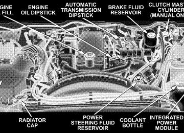
In case of engine runaway due to flammable fumes from gasoline spills or turbocharger oil leaks being sucked into the engine, do the following to help avoid personal injury and/or vehicle damage: 1. Shut off engine ignition switch. 2. Using a CO2 or dry chemical type fire extin- guisher, direct the spray from the fire extinguisher into the grille on the passenger side so that the spray enters the engine air intake. The inlet for the engine air intake is located behind the passenger side headlamp and receives air through the grille.
348 STARTING AND OPERATING
FUEL REQUIREMENTS
Fuel Requirements (6.7L Diesel Engines) Use good quality diesel fuel from a reputable supplier in your vehicle. Federal law requires that you must fuel this vehicle with Ultra Low Sulfur Highway Diesel fuel (15
ppm Sulfur maximum) and prohibits the use of Low Sulfur Highway Diesel fuel (500 ppm Sulfur maximum) to avoid damage to the emissions control system. For most year-round service, No. 2 diesel fuel meeting ASTM specification D-975 Grade S15 will provide good perfor- mance. If the vehicle is exposed to extreme cold (below 20°F or -7°C), or is required to operate at colder-than- normal conditions for prolonged periods, use climatized No. 2 diesel fuel or dilute the No. 2 diesel fuel with 50% No. 1 diesel fuel. This will provide better protection from fuel gelling or wax-plugging of the fuel filters.WARNING!
Do not use alcohol or gasoline as a fuel blending agent. They can be unstable under certain conditions and hazardous or explosive when mixed with diesel fuel.
Diesel fuel is seldom completely free of water. To prevent fuel system trouble, drain the accumulated water from the fuel/water separator using the fuel/water separator drain provided. If you buy good quality fuel and follow the cold weather advice above, fuel conditioners should not be required in your vehicle. If available in your area, a high cetane “premium” diesel fuel may offer improved cold-starting and warm-up performance.
Fuel Specifications The Cummins Turbocharged, Charge Air Cooled, Diesel engine has been developed to take advantage of the high energy content and generally lower cost No. 2 Ultra Low Sulfur diesel fuel or No. 2 Ultra Low Sulfur climatized diesel fuels. Experience has shown that it also operates on No. 1 Ultra Low Sulfur diesel fuels or other fuels within specification. NOTE: A maximum blend of 5% biodiesel meeting ASTM specification D-6751 may be used with your Cummins Diesel equipped vehicle. In addition, commercially available fuel addi- NOTE: tives are not necessary for the proper operation of your Cummins Diesel equipped vehicle. NOTE: No. 1 Ultra Low Sulfur diesel fuel should only be used where extended arctic conditions (-10°F or -23°C) exist.
STARTING AND OPERATING 349
ADDING FUEL (DIESEL ENGINES)
CAUTION!
To avoid fuel spillage and overfilling, do not “top off” the fuel tank after filling.
tank is full.
NOTE: † When the fuel nozzle “clicks” or shuts off, the fuel † Tighten the gas cap until you hear a “clicking” sound. This is an indication that the gas cap is properly tightened. † Make sure that the gas cap is tightened each time the
vehicle is refueled.
350 STARTING AND OPERATING
WARNING!
CAUTION!
A fire may result if fuel is pumped into a portable container that is on a truck bed. You could be burned. Always place fuel containers on the ground while filling.
Damage to the fuel system or emission control sys- tem could result from using an improper fuel tank filler tube cap (gas cap). A poorly fitting cap could let impurities into the fuel system.
Fuel Filler Cap (Gas Cap)
The gas cap is behind the fuel filler door. If the gas cap is lost or damaged, be sure the replacement cap is for use with this vehicle.
WARNING!
† Never have any smoking materials lit in or near the vehicle when the gas cap is removed or the tank filled. † Never add fuel to the vehicle when the engine is
running.
Avoid Using Contaminated Fuel Fuel that is contaminated by water or dirt can cause severe damage to the engine fuel system. Proper main- tenance of the engine fuel filter and fuel tank is essential. (See Section 7 for Maintenance Procedures). NOTE: Climatized diesel fuel is a blend of Number 2
and Number 1 Diesel fuel which reduces the temperature at which wax crystals form in the fuel. Bulk Fuel Storage If you store quantities of fuel, good maintenance of the stored fuel is also essential. Fuel contaminated with water will promote the growth of “microbes.” These microbes form “slime” that will clog fuel filters and lines. Drain condensation from the supply tank and change the line filter on a regular basis. NOTE: When a diesel engine is allowed to run out of fuel, air is pulled into the fuel system.STARTING AND OPERATING 351
You may try priming as described below. However, if the engine will not start, refer to the fuel priming procedure in the Service Manual or have the vehicle towed to an authorized Dodge dealer.
WARNING!
Do not open the high pressure fuel system with the engine running. Engine operation causes high fuel pressure. High pressure fuel spray can cause serious injury or death.
Priming if the engine has run out of fuel 1. Add a substantial quantity of fuel to the tank 5 to 10
gallons (19 to 38L).352 STARTING AND OPERATING
2. Crank the engine for 1 to 2 seconds. If the engine does not start, then release the key or starter button back to the RUN position (do not turn the key back to the OFF position). The electric fuel transfer pump will continue to run and purge air from the system for about 20 seconds. After 20 seconds, attempt to start the engine again. 3. Start the engine using the Normal Starting Procedure. 4. Repeat the procedure if the engine does not start.
CAUTION!
Do not engage the starter motor for more than 15
seconds at a time. Allow two minutes between the cranking intervals.NOTE: The engine may run rough until the air is forced from all the fuel lines.
VEHICLE LOADING
Certification Label As required by National Highway Traffic Safety Admin- istration regulations, your vehicle has a certification label affixed to the driver’s side door or pillar. This label contains the month and year of manufacture, Gross Vehicle Weight Rating (GVWR), Gross Axle Weight Rating (GAWR) front and rear, and Vehicle Identification Number (VIN). A Month-Day-Hour (MDH) number is included on this label and indicates the Month, Day and Hour of manufacture. The bar code that appears on the bottom of the label is your Vehicle Identification Number (VIN).
Gross Vehicle Weight Rating (GVWR) The GVWR is the total permissible weight of your vehicle including driver, passengers, vehicle, options and cargo. The label also specifies maximum capacities of front and rear axle systems (GAWR). Total load must be limited so GVWR and front and rear GAWR are not exceeded. Payload The payload of a vehicle is defined as the allowable load weight a truck can carry, including the weight of the driver, all passengers, options and cargo. Gross Axle Weight Rating (GAWR) The GAWR is the maximum permissible load on the front and rear axles. The load must be distributed in the cargo area so that the GAWR of each axle is not exceeded.
STARTING AND OPERATING 353
Each axle GAWR is determined by the components in the system with the lowest load carrying capacity (axle, springs, tires or wheels). Heavier axles or suspension components sometimes specified by purchasers for in- creased durability does not necessarily increase the vehi- cle’s GVWR. Tire Size The tire size on the Label represents the actual tire size on your vehicle. Replacement tires must be equal to the load capacity of this tire size. Rim Size This is the rim size that is appropriate for the tire size listed. Inflation Pressure This is the cold tire inflation pressure for your vehicle for all loading conditions up to full GAWR.
354 STARTING AND OPERATING
Curb Weight The curb weight of a vehicle is defined as the total weight of the vehicle with all fluids, including vehicle fuel, at full capacity conditions, and with no occupants or cargo loaded into the vehicle. The front and rear curb weight values are determined by weighing your vehicle on a commercial scale before any occupants or cargo are added. Loading The actual total weight and the weight of the front and rear of your vehicle at the ground can best be determined by weighing it when it is loaded and ready for operation. The entire vehicle should first be weighed on a commer- cial scale to insure that the GVWR has not been exceeded. The weight on the front and rear of the vehicle should then be determined separately to be sure that the load is properly distributed over front and rear axle. Weighing the vehicle may show that the GAWR of either the front
or rear axles has been exceeded but the total load is within the specified GVWR. If so, weight must be shifted from front to rear or rear to front as appropriate until the specified weight limitations are met. Store the heavier items down low and be sure that the weight is distributed equally. Stow all loose items securely before driving. Improper weight distributions can have an adverse effect on the way your vehicle steers and handles and the way the brakes operate.
CAUTION!
Do not load your vehicle any heavier than the GVWR or the maximum front and rear GAWR. If you do, parts on your vehicle can break, or it can change the way your vehicle handles. This could cause you to lose control. Also overloading can shorten the life of your vehicle.
An EXAMPLE of a loaded vehicle is shown in the following chart. Note that neither GVWR nor GAWR capabilities are exceeded. Overloading can cause poten- tial safety hazards and shorten service life.
NOTE: The weights shown in this chart are not necessarily the weights for your vehicle. Also, the amount of load added to both the front and rear axles can be computed after the vehicle has been weighed both in its (curb weight( condition, and in its (loaded and ready for operation( condition.
STARTING AND OPERATING 355
Gross Vehicle Weight Rating (GVWR) 6500 LBS (2948 kg).
356 STARTING AND OPERATING
TRAILER TOWING In this section you will find safety tips and information on limits to the type of towing you can reasonably do with your vehicle. Before towing a trailer carefully re- view this information to tow your load as efficiently and safely as possible. To maintain warranty coverage, follow the requirements and recommendations in this manual concerning ve- hicles used for trailer towing. Common Towing Definitions The following trailer towing related definitions will assist you in understanding the following information: Gross Vehicle Weight Rating (GVWR) The GVWR is the total allowable weight of your vehicle. This includes driver, passengers, cargo and tongue weight. The total load must be limited so that you do not exceed the GVWR.
Gross Trailer Weight (GTW) The gross trailer weight (GTW) is the weight of the trailer plus the weight of all cargo, consumables and equipment (permanent or temporary) loaded in or on the trailer in its 9loaded and ready for operation9 condition. The recom- mended way to measure GTW is to put your fully loaded trailer on a vehicle scale. The entire weight of the trailer must be supported by the scale. Gross Combination Weight Rating (GCWR) The gross combination weight rating (GCWR) is the total permissible weight of your vehicle and trailer when weighed in combination. (Note that GCWR ratings in- clude a 68 kg (150 lbs) allowance for the presence of a driver).
Gross Axle Weight Rating (GAWR) The GAWR is the maximum capacity of the front and rear axles. Distribute the load over the front and rear axles evenly. Make sure that you do not exceed either front or rear GAWR.
WARNING!
It is important that you do not exceed the maximum front or rear GAWR. A dangerous driving condition can result if either rating is exceeded. You could lose control of the vehicle and have an accident.
Tongue Weight (TW) The downward force exerted on the hitch ball by the trailer. In most cases it should not be less than 10% or more than 15% of the trailer load. You must consider this as part of the load on your vehicle.
STARTING AND OPERATING 357
Frontal Area The maximum height and maximum width of the front of a trailer. Trailer Sway Control The trailer sway control is a telescoping link that can be installed between the hitch receiver and the trailer tongue that typically provides adjustable friction associated with the telescoping motion to dampen any unwanted trailer swaying motions while traveling. Weight-Carrying Hitch A weight-carrying hitch supports the trailer tongue weight, just as if it were luggage located at a hitch ball or some other connecting point of the truck. These kind of hitches are the most popular on the market today and they’re commonly used to tow small- and medium-sized trailers.
358 STARTING AND OPERATING
Weight-Distributing Hitch A weight-distributing system works by applying lever- age through spring (load) bars. They are typically used for heavier loads, to distribute trailer tongue weight to the tow vehicle’s front axle and the trailer axle(s). When used in accordance with the manufacturers’ directions, it provides for a more level ride, offering more consistent steering and brake control thereby enhancing towing safety. The addition of a friction / hydraulic sway control also dampens sway caused by traffic and crosswinds and contributes positively to tow vehicle and trailer stability. Trailer sway control and a weight distributing (load equalizing) hitch are recommended for heavier Tongue Weights (TW) and may be required depending on Vehicle and Trailer configuration / loading to comply with gross axle weight rating (GAWR) requirements.
WARNING!
An improperly adjusted Weight Distributing Hitch system may reduce handling, stability, braking per- formance, and could result in an accident. Weight Distributing Systems may not be compatible with Surge Brake Couplers. Consult with your hitch and trailer manufacturer or a reputable Recreational Vehicle dealer for additional information.
STARTING AND OPERATING 359
Weight-Distributing Hitch System
Improper Adjustment Of Weight-Distributing System
360 STARTING AND OPERATING
Fifth-Wheel Hitch A special high platform with a coupling that mounts over the rear axle of the tow vehicle in the truck bed. Connects a vehicle and fifth-wheel trailer with a coupling king pin. Gooseneck Hitch The gooseneck hitch employs a pivoted coupling arm which attaches to a ball mounted in the bed of a pickup truck. The coupling arm connects to the hitch mounted over the rear axle in the truck bed. Trailer Hitch Classification The rear bumper is intended to tow trailers up to 2,000
lbs (907 kg) without added equipment or alterations to the standard equipment. Your vehicle may be factory equipped for safe towing of trailers weighing over 2,000
lbs (907 kg) with the optional Trailer Tow Prep Package. See your dealer for package content. The following chart provides the industry standard for the maximum trailer weight a given trailer hitch class cantow and should be used to assist you in selecting the correct trailer hitch for your intended towing condition. Refer to “Trailer Towing Weights (Maximum Trailer Weight Ratings)” for the website address that contains the necessary information for your specific drivetrain.
Trailer Hitch Classification
Class
Max. GTW
(Gross Trailer Wt.) 2,000 lbs (907 kg) 3,500 lbs (1587 kg)
Class I - Light Duty Class II - Medium Duty Class III - Heavy Duty Class IV - Extra Heavy Duty Fifth Wheel/ Gooseneck All trailer hitches should be professionally installed on your vehicle.
5,000 lbs (2268 kg) 10,000 lbs (4540 kg)
Greater than 10,000 lbs
(4540 kg)
Trailer Towing Weights (Maximum Trailer Weight Ratings)
Never exceed the maximum tongue weight stamped on your bumper or trailer hitch.
STARTING AND OPERATING 361
NOTE: For additional trailer towing information (maxi- mum trailer weight ratings) refer to the following website addresses: † http:// www.dodge.com/towing. † http:// www.dodge.ca (Canada). Trailer and Tongue Weight Always load a trailer with 60% to 65% of the weight in the front of the trailer. This places 10% to 15% of the Gross Trailer Weight (GTW) on the tow hitch of your vehicle. Loads balanced over the wheels or heavier in the rear can cause the trailer to sway severely side to side which will cause loss of control of vehicle and trailer. Failure to load trailers heavier in front is the cause of many trailer accidents.
Consider the following items when computing the weight on the rear axle of the vehicle: † The tongue weight of the trailer.
362 STARTING AND OPERATING
put in or on your vehicle.
† The weight of any other type of cargo or equipment † The weight of the driver and all passengers. NOTE: Remember that everything put into or on the trailer adds to the load on your vehicle. Also, additional factory-installed options, or dealer-installed options, must be considered as part of the total load on your vehicle. Refer to the Tire and Loading Information plac- ard in the Tire Safety Information Section of this manual. Towing Requirements To promote proper break-in of your new vehicle driv- etrain components the following guidelines are recom- mended:
CAUTION!
† Avoid towing a trailer for the first 500 miles (805
km) of vehicle operation. Doing so may damage your vehicle. † During the first 500 miles (805 km) of trailertowing, limit your speed to 50 mph (80 km/h).
WARNING!
Your vehicle may require special axle lubricant. Please refer to the fluids section of this manual.
Perform the maintenance listed in Section 8 of this manual. When towing a trailer, never exceed the GAWR, or GCWR, ratings.
WARNING!
Improper towing can lead to an injury accident. Follow these guidelines to make your trailer towing as safe as possible: Make certain that the load is secured in the trailer and will not shift during travel. When trailering cargo that is not fully secured, dynamic load shifts can occur that may be difficult for the driver to control. You could lose control of your vehicle and have an accident.
† When hauling cargo or towing a trailer, do not over- load your vehicle or trailer. Overloading can cause a loss of control, poor performance or damage to brakes, axle, engine, transmission, steering, suspension, chas- sis structure or tires.
STARTING AND OPERATING 363
† Safety chains must always be used between your vehicle and trailer. Always connect the chains to the frame or hook retainers of the vehicle hitch. Cross the chains under the trailer tongue and allow enough slack for turning corners. † Vehicles with trailers should not be parked on a grade. When parking, apply the parking brake on the tow vehicle. Put the tow vehicle automatic transmission in P for Park. With a manual transmission, shift the transmission into reverse. And with four-wheel-drive vehicles, make sure the transfer case is not in neutral. Always, block or 9chock9 the trailer wheels.
† GCWR must not be exceeded. † Total weight must be distributed between the tow vehicle and the trailer such that the following four ratings are not exceeded: 1. GVWR
364 STARTING AND OPERATING
2. GTW 3. GAWR 4. Tongue weight rating for the trailer hitch utilized (This requirement may limit the ability to always achieve the 10% to 15% range of tongue weight as a percentage of total trailer weight).
Towing Requirements — Tires − Do not attempt to tow a trailer while using a compact
spare tire.
− Proper tire inflation pressures are essential to the safe and satisfactory operation of your vehicle. Refer to the Tires–General Information section of this manual on Tire Pressures for proper tire inflation procedures.
− Also, check the trailer tires for proper tire inflation
pressures before trailer usage.
− Check for signs of tire wear or visible tire damage before towing a trailer. Refer to the Tires–General Information section of this manual on Tread Wear Indicators for the proper inspection procedure.
− When replacing tires refer to the Tires–General Infor- mation section of this manual on Replacement Tires for proper tire replacement procedures. Replacing tires with a higher load carrying capacity will not increase the vehicle’s GVWR and GAWR limits. Towing Requirements — Trailer Brakes − Do not interconnect the hydraulic brake system or vacuum system of your vehicle with that of the trailer. This could cause inadequate braking and possible personal injury.
− An electronically actuated trailer brake controller is required when towing a trailer with electronically actuated brakes. When towing a trailer equipped with a hydraulic surge actuated brake system, an electronic brake controller is not required.
− Trailer brakes are recommended for trailers over 1,000
lbs (454 kg) and required for trailers in excess of 2,000
lbs (907 kg).CAUTION!
If the trailer weighs more than 1,000 lbs (454 kg) loaded, it should have its own brakes and they should be of adequate capacity. Failure to do this could lead to accelerated brake lining wear, higher brake pedal effort, and longer stopping distances.
STARTING AND OPERATING 365
WARNING!
Do not connect trailer brakes to your vehicle’s hy- draulic brake lines. It can overload your brake sys- tem and cause it to fail. You might not have brakes when you need them and could have an accident. Towing any trailer will increase your stopping dis- tance. When towing you should allow for additional space between your vehicle and the vehicle in front of you. Failure to do so could result in an accident.
Towing Requirements — Trailer Lights & Wiring Whenever you pull a trailer, regardless of the trailer size, stop lights and turn signals on the trailer are required for motoring safety.
366 STARTING AND OPERATING
The Trailer Tow Package may include a 4 and 7 pin wiring harness. Use a factory approved trailer harness and connector. NOTE: Do not cut or splice wiring into the vehicles wiring harness. The electrical connections are all complete to the vehicle but you must mate the harness to a trailer connector. Refer to the following illustrations.
4-Pin Connector
STARTING AND OPERATING 367
WARNING!
Any work done to the vehicles electrical system, or wiring, should be performed by a qualified automo- tive technician, if done improperly it may cause damage to the electrical system wiring and could result in serious or fatal injury.
The following chart identifies the maximum electrical loads that the trailer tow output circuits are capable of supporting.
7-Pin Connector
368 STARTING AND OPERATING
Trailer Tow Additional Lamp Loads
Output Functions
Maximum Current
Stop/Turn Left
Stop/Turn Right
Trailer Park Lamps
16A
16A
14A
Additional Bulbs Allowed Example Only. Other bulb combinations can be used as long as maximum cur-
rent is not ex-
ceeded.
2 #3157 bulbs for stop/turn 2 #3157 bulbs for stop/turn
2 #1157 bulbs (two filament
park/stop/turn)
plus up to 24
#168 or #194 pea-
nut bulbs.
Towing Tips Before setting out on a trip, practice turning, stopping and backing the trailer in an area away from heavy traffic. If using a manual transmission vehicle for trailer towing, all starts must be in FIRST gear to avoid excessive clutch slippage. Towing Tips — Automatic Transmission The “D” range can be selected when towing. However, if frequent shifting occurs while in this range, select 9TOW/ HAUL9 mode or select a lower gear using the Auto-6
(ERS) switch. NOTE: Using the “TOW HAUL” range while operating the vehicle under heavy operating conditions will im- prove performance and extend transmission life by re- ducing excessive shifting and heat build up. This action will also provide better engine braking.The automatic transmission fluid and filter should be changed if you REGULARLY tow a trailer for more than 45 minutes of continuous operation. See Maintenance Schedule in section 8 of this manual for transmission fluid change intervals. NOTE: Check the automatic transmission fluid level before towing. Towing Tips — Tow/Haul (If Equipped) To reduce potential for automatic transmission overheat- ing, turn the “TOW HAUL” feature ON when driving in hilly areas or downshift the transmission (using the Auto-6 [ERS] switch). Towing Tips — Electronic Speed Control (If Equipped) − Don’t use in hilly terrain or with heavy loads.
STARTING AND OPERATING 369
− When using the speed control, if you experience speed drops greater than 10 mph (16 km/h), disengage until you can get back to cruising speed.
− Use speed control in flat terrain and with light loads to
maximize fuel efficiency.
Towing Tips — Cooling System To reduce potential for engine and transmission over- heating, take the following actions: − City Driving When stopped for short periods of time, put transmission in neutral and increase engine idle speed. − Highway Driving Reduce speed. − Air Conditioning Turn off temporarily.
370 STARTING AND OPERATING
− refer to Cooling System Operating information in the Maintenance section of this manual for more informa- tion.
Trailer Towing Mirrors — If Equipped These mirrors are designed with an adjustable mirror head to provide a greater vision range when towing extra-wide loads. To change position inboard or out- board, the mirror head should be rotated (flipped Out or In). A small blindspot mirror is integrated onto the main mirror surface. NOTE: rearward prior to entering an automated car wash.
Fold the 7 x 10 inch trailer towing mirrors
Blindspot Mirror
STARTING AND OPERATING 371
follow the recommendations contained within the cur- rent Dodge BODY BUILDER’S GUIDE. See your dealer, installer or snowplow manufacture for this information. There are unique electrical systems that must be con- nected to properly assure operator safety and prevent overloading vehicle systems.
WARNING!
Attaching a snowplow to this vehicle could adversely affect performance of the airbag system in an acci- dent. Do not expect that the airbag will perform as described earlier in this manual
CAUTION!
The “Lamp Out” indicator could illuminate if exte- rior lamps are not properly installed.
Trailer Towing Position
SNOWPLOW Snowplow Prep Packages are available as a factory installed option. These packages include components necessary to equip your vehicle with a snowplow. NOTE: Before installation of a snowplow it is highly recommended that the owner / installer obtain and
372 STARTING AND OPERATING
level.
Before plowing † Check the hydraulic system for leaks and proper fluid † Check the mounting bolts and nuts for proper tight- † Check the runners and cutting edge for excessive wear. The cutting edge should be 1/4 to 1/2 inch above ground in snow plowing position. † Check that snowplow lighting is connected and func-
ness.
tioning properly.
Snowplow Prep Package Model Availability For Information about snowplow applications visit www.dodge.com or refer to the current Dodge Body Builders Guide. 1. The maximum number of occupants in the truck should not exceed two.
2. The total GVWR or the Front GAWR or the Rear GAWR should never be exceeded. 3. The snowplow prep packages are not available with the Sport Package. 4. Cargo capacity will be reduced by the addition of options or passengers, etc. The loaded vehicle weight, including the snowplow system, all aftermarket accessories, driver, passengers, options, and cargo, must not exceed either the Gross Vehicle Weight (GVWR) or Gross Axle Weight (GAWR) ratings. These weights are specified on the Safety Com- pliance Certification Label on the driver’s side door opening. NOTE: Detach the snowplow when transporting pas- sengers. Vehicle front end wheel alignment was set to specifica- tions at the factory without consideration for the weight
if necessary at
of the plow. Front end tow-in should be checked and reset the beginning and end of the snowplow season. This will help prevent uneven tire wear. The blade should be lowered whenever the vehicle is parked. Maintain and operate your vehicle and snowplow equip- ment following the recommendations provided by the specific snowplow manufacturer. Over the Road Operation With Snowplow Attached The blade restricts air flow to the radiator and causes the engine to operate at higher than normal temperatures. Therefore, when transporting the plow, angle the blade completely and position it as low as road or surface conditions permit. Do not exceed 40 mph (64 km/h). The operator should always maintain a safe stopping distance and allow adequate passing clearance.
STARTING AND OPERATING 373