- 2009 Dodge RAM Diesel Owners Manuals
- Dodge RAM Diesel Owners Manuals
- 2010 Dodge RAM Diesel Owners Manuals
- Dodge RAM Diesel Owners Manuals
- 2005 Dodge RAM Diesel Owners Manuals
- Dodge RAM Diesel Owners Manuals
- 2006 Dodge RAM Diesel Owners Manuals
- Dodge RAM Diesel Owners Manuals
- 2008 Dodge RAM Diesel Owners Manuals
- Dodge RAM Diesel Owners Manuals
- 2004 Dodge RAM Diesel Owners Manuals
- Dodge RAM Diesel Owners Manuals
- 2007 Dodge RAM Diesel Owners Manuals
- Dodge RAM Diesel Owners Manuals
- Download PDF Manual
-
cellular phone at any time.
Making a Phone Call Using Digit Dialing † Press the ’Phone’ button to begin. † After the 9Ready9 prompt, say 9Dial9 or 9Call9 followed by the phone number you wish to dial. For example, you can say 9Dial” wait for ready prompt 123 456 7890. The phone number that you enter must be a valid length.
Making a Phone Call Using Your UConnect™ Phonebook † Press the “Phone” button to begin.
† After the 9Ready9 prompt, say 9Dial9 or 9Call9 wait for the ready prompt followed by the name and designa- tion of a phonebook entry that you wish to dial. For example, you can say 9Call John Doe Work9. Add Names to Your UConnect™ Phonebook † Press the “Phone” button to begin. † After the 9Ready9 prompt, say 9Phonebook New Entry9. † Or, After the 9Ready9 prompt, say “Phonebook”. † When prompted, say “New Entry”. † When prompted, say the name of the new entry. † Next, enter the number designation (e.g. “Home”, “Work”, “Mobile”, or “Pager”). This will allow you to have multiple numbers for each phonebook entry. † Recite the phone number for the phonebook entry that
you are adding.
UNDERSTANDING THE FEATURES OF YOUR VEHICLE 83
After you are finished adding an entry into the phone- book, you will be given the opportunity to add more phone numbers to the current entry or to return to the main menu. The UConnect™ system will allow you to enter up to 32
names into the phonebook with each name having up to four associated phone numbers and designations. Edit Entries in the UConnect™ Phonebook † Press the ’Phone’ button to begin. † After the 9Ready9 prompt, say 9Phonebook Edit9. † You will then be asked for the name of the phonebook † Next, choose the number designation that you wish to edit. The choices are home, work, mobile, or pager. † Recite the new phone number for the phonebook entryentry that you wish to edit.
that you are editing.
84 UNDERSTANDING THE FEATURES OF YOUR VEHICLE
After you are finished editing an entry in the phonebook, you will be given the opportunities to edit another entry in the phonebook, call the number you just edited, or return to the main menu. Phonebook edit can be used to add another phone number to a name entry that already exists in the phonebook. For example, the entry John Doe may have a mobile and a home number, but you can add John Doe’s work number later through phonebook edit. Delete Entries in the UConnect™ Phonebook † Press the ’Phone’ button to begin. † After the 9Ready9 prompt, say 9Phonebook Delete9. † After you enter the phonebook delete menu, you will then be asked for the name of the phonebook entry that you wish to delete. You can either say the name of a phonebook entry that you wish to delete or you can say 9List Names9 to hear a list of the entries in the
phonebook from which you can choose. To select one of the entries from the list, press the 9Voice Recogni- tion9 button while the UConnect™ system is playing the desired entry and say 9Delete9. † After you enter the name, the UConnect™ system will ask you if you wish to delete the home, work, mobile, or pager number for this entry.
Delete All Entries in the UConnect™ Phonebook † Press the ’Phone’ button to begin. † After the 9Ready9 prompt, say 9Phonebook Delete All9. † The UConnect™ system will ask you to verify that you † After confirmation, the phonebook entries will be
wish to delete all the entries from the phonebook.
deleted.
Names9.
phonebook entries.
List All Names in the UConnect™ Phonebook † Press the ’Phone’ button to begin. † After the 9Ready9 prompt, say 9Phonebook List † The UConnect™ system will play the names of all the † To call one of the names in the list, press the ’Voice Recognition’ button during the playing of the desired name and say 9Call9. † The UConnect™ system will then prompt you as to number designation you wish to call. † The selected number will be dialed.
UNDERSTANDING THE FEATURES OF YOUR VEHICLE 85
Phone Call Features The following feature(s) can be accessed through the UConnect™ system if the feature(s) are available on your cellular service plan. For example, if your cellular service plan provides three-way calling, this feature can be accessed through the UConnect™ system. Answer or Reject an Incoming Call - No Call Currently in Progress When you receive a call on your cellular phone, the UConnect™ system will interrupt the stereo audio and will ask if you would like to answer the call by pressing the ’Phone’ button. Press the ’Phone’ button to answer the call. To reject the call, press the ’Phone’ button until you hear a single beep indicating that the incoming call was rejected.
86 UNDERSTANDING THE FEATURES OF YOUR VEHICLE
Answer or Reject an Incoming Call - Call Currently in Progress If a call is currently in progress and you have another incoming call, press the ’Phone’ button to place the current call on hold and answer the incoming call. To reject the incoming call, you can disregard the call and continue with your current conversation. Making a Second Call while Current Call in Progress To make a second call while you are currently in a call, press the ’Voice Recognition’ button and say 9Dial9 or 9Call9 followed by the phone number or phonebook entry you wish to call. The first call will be on hold while the second call is in progress.
Putting a Call on Hold and Retrieving a Call from Hold To put a call on hold, press the ’Phone’ button until you hear a single beep which will indicate that the call has been placed on hold. To bring the call back from hold, press the ’Phone’ button. Toggling Between Two Calls If two calls are in progress (one active and one on hold), press the ’Phone’ button until you hear a single beep indicating that the active and hold status of the two calls have switched. Only one call can be placed on hold at one time. Conference Call When two calls are in progress (one active and one on hold), press the ’Phone’ button until you hear a double beep indicating that the two calls have been joined into one conference call.
Three-Way Calling To initiate three-way calling, press the ’Voice Recogni- tion’ button while a call is in progress and make a second phone call. When the second call is established, press the ’Phone’ button until you hear a double beep indicating that the two calls have been joined into one conference call. Call Termination To end a call in progress, press the ’Phone’ button. All calls in progress will be terminated. Phone Redial † Press the ’Phone’ button to begin. † After the 9Ready9 prompt, say 9Redial9. † The UConnect™ system will call the last number that was dialed on your cellular phone. This may not be the last number dialed by your UConnect™ system.
UNDERSTANDING THE FEATURES OF YOUR VEHICLE 87
Advanced Phone Connectivity
Transferring an Active Call between the UConnect™ System and Your Cellular Phone The UConnect™ system allows ongoing calls to be trans- ferred to your cellular phone or to the UConnect™ system without terminating the call. To transfer an ongo- ing call from your cellular phone to the UConnect™ system or vice versa, press the ’Voice Recognition’ button and say 9Transfer Call9. Delete Paired Cellular Phones † Press the ’Phone’ button to begin. † After the 9Ready9 prompt, say 9Setup9. † When prompted, say “ Phone Pairing”. † At the next prompt, say 9Delete9.
88 UNDERSTANDING THE FEATURES OF YOUR VEHICLE
† You will be asked to say the name of the phone that you wish to delete. You can either say the name of the phone that you wish to delete or you can say 9All9 to delete all the phones.
Connect or Disconnect the Connection between the UConnect™ System and Your Cellular Phone Your cellular phone can be paired with many different electronic devices, but can only be actively 9connected9
with one electronic device at a time. If you would like to connect or disconnect the Blue- tooth™ connection between a paired cellular phone and the UConnect™ system, follow the instruction described in your cellular phone user’s manual. List Paired Cellular Phone Names † Press the ’Phone’ button to begin.† After the 9Ready9 prompt, say 9Setup List Phones9 and the UConnect™ system will play the phone names of all paired cellular phones in order from highest prior- ity to lowest priority.
Select a Lower Priority Paired Cellular Phone † Press the ’Phone’ button to begin. † After the 9Ready9 prompt, say 9Setup9. † When prompted, say “Select Phone”. † When prompted, say the phone name of the cellular phone you wish to use, or say 9List Phones9 to hear a list of all the phones that have been paired to your UConnect™ system. To select a phone from the list, press the ’Voice Recognition’ button and say 9Select9.
† The lower priority phone will only be used for the next phone call. After that, the UConnect™ system will return to using the highest priority phone in the vehicle.
UConnect™ System Features
Barge In - Touch Tone Phone Inputs You can use your UConnect™ system to access a voice mail system, an automated service, or any other phone number that you can dial with any phone. When calling a number with your UConnect™ system that normally requires you to enter in a touch-tone sequence on your cellular phone keypad, you can push the ’Voice Recogni- tion’ button and say the sequence you wish to enter followed by 9Send9. For example, if required to enter your pin number, you can press the ’Voice Recognition’ button and say 93 7 4 6 Send9, or whatever you have made your pin. This method can also be used in instances where you
UNDERSTANDING THE FEATURES OF YOUR VEHICLE 89
are pressing a number on your keypad to navigate through a menu structure or to enter a number for a pager. Barge In - Overriding Prompts The ’Voice Recognition’ button can be used when you wish to skip part of a prompt and issue your voice recognition command immediately. For example, if a prompt is playing 9Would you like to pair a phone, clear a{9, you could press the ’Voice Recognition’ button and say 9Pair A Phone9 to select that option without having to listen to the rest of the voice prompt. Language Selection To change the language that the UConnect™ system is using, press the ’Phone’ button and say the name of the language you wish to switch to (English, Español, or Français as equipped). After selecting one of the lan- guages, all prompts and voice commands will be in the selected language.
90 UNDERSTANDING THE FEATURES OF YOUR VEHICLE
Turning Confirmation Prompts On/Off Turning confirmation prompts off will stop the system from confirming your choices (e.g. the UConnect™ sys- tem will not repeat a phone number before you dial it). † Press the ’Phone’ button to begin. † After the 9Ready9 prompt, say 9Setup Confirmation9. The UConnect™ system will play the current confir- mation prompt status and you will be given the choice to change it.
Low Signal, Battery Strength, and Roam Notification The UConnect™ system will provide notification to inform you if your cellular phone is in roaming status, has low signal strength, or has a low battery when you are trying to place a phone call.
Dialing Using the Cellular Phone Keypad You can dial a phone number with your cellular phone keypad and still use the UConnect™ system. By dialing a number with your paired Bluetooth™ cellular phone, the audio will be played through your vehicle’s stereo sys- tem. The UConnect™ system will work the same as if you dialed the number using voice recognition. Mute/Unmute When you mute the UConnect™ system, you will still be able to hear the conversation coming from the other party, but the other party will not be able to hear you. In order to mute the UConnect™ system press the ’Voice Recognition’ button and say 9Mute9. In order to unmute the UConnect™ system; press the ’Voice Recognition’ button and say 9Unmute9.
Help If you need assistance at any prompt or if you want to know what your options are at any prompt, say 9Help9. The UConnect™ system will play all the options at any prompt if you ask for help. Cancel At any prompt, you can say 9Cancel9 and you will be returned to the previous menu. Emergency Assistance If you are in an emergency, say 9Dial Emergency9 or 9Call Emergency9 and the UConnect™ system will instruct your cellular phone to call 911. Towing Assistance If you need towing assistance, say 9Dial Towing Assis- tance9 or 9Call Towing Assistance9. Please refer to the 24-Hour Towing Assistance coverage details in the DaimlerChrysler Motors Company 24-Hour Towing As- sistance Program Guide.
UNDERSTANDING THE FEATURES OF YOUR VEHICLE 91
SEATS The seating options available in this truck are the result of extensive customer research and evaluations.
WARNING!
It is extremely dangerous to ride in a cargo area, inside or outside of a vehicle. In a collision, people riding in these areas are more likely to be seriously injured or killed. Do not allow people to ride in any area of your vehicle that is not equipped with seats and seat belts. Be sure everyone in your vehicle is in a seat and using a seat belt properly.
92 UNDERSTANDING THE FEATURES OF YOUR VEHICLE
40-20-40 Front Seat
As the name implies, the seat is divided into 3 segments. The outboard seat portions are each 40% of the total width of the seat. The back of the center portion (20%) easily folds down to provide an armrest/center storage compartment (if equipped).
Each outboard seat is independently adjustable forward or backward and is equipped with a back recliner. The manual seat adjustment handle is found at the front edge of each seat cushion. Pull up on the handle and slide the seat to get the most comfortable position.
WARNING!
Adjusting a seat while the vehicle is moving is dangerous. The sudden movement of the seat could cause you to lose control. The seat belt might not be properly adjusted and you could be injured. Adjust any seat only while the vehicle is parked.
Reclining Seats The recliner handle is on the outside of the seat cushion. Pull up on the handle to release the seat back and adjust for comfort.
UNDERSTANDING THE FEATURES OF YOUR VEHICLE 93
WARNING!
You can be seriously, even fatally injured riding in a seat with the seatback reclined. Do not ride with the seatback reclined so that the shoulder belt is no longer resting against your chest. If you ride in this position, the shoulder harness will no longer be restraining you. In a collision you could slide under the seat belt and receive serious or fatal injuries. Recline in a seat only when the vehicle is parked.
Adjustable Head Restraints Head restraints can reduce the risk of whiplash injury in the event of impact from the rear. Pull up or push down on the restraints so that the upper edge is as high as practical, at least to the level of the ears.
94 UNDERSTANDING THE FEATURES OF YOUR VEHICLE
To lower the head restraint, push in the button and then push down on the head restraint.
Manual Rotary Lumbar Support Adjustment — If Equipped Rotating the lumbar control knob on the left side of the driver’s seatback and on the right side of the passenger’s seatback increases or decreases the lumbar support.
Lumbar Adjustment
Power Seats — If Equipped
CAUTION!
Don’t put anything under a power seat. It may cause damage to the seat controls.
UNDERSTANDING THE FEATURES OF YOUR VEHICLE 95
Up, Down, Forward, and Rearward
The power seat controls are on the outboard side of the front seat cushions. Three switches control the seat move- ment. The four-way switch in the center can be moved forward or backwards to get the most comfortable posi- tion. The same switch can be moved up and down to
96 UNDERSTANDING THE FEATURES OF YOUR VEHICLE
control seat height. Change the seat angle by using the two toggle switches, tilting it up or down.
Heated Seats — If Equipped The heated seat switches are located in the instrument panel under the climate controls. The engine must be running for the heated seats to operate.
Tilt Adjustment
Each heated seat switch has two settings (HI and LOW). Press the switch once to obtain the desired heating position and press a second time in the same direction to turn the heated seats OFF. If you do not purposefully turn the switch OFF, the heating element in the seat will remain activated until the ignition is turned off. The indicators on the switch will illuminate when the heated seats are in the (HI or LOW) position. Flashing telltale lights on the switch indicate that the Heated Seat system needs servicing.
UNDERSTANDING THE FEATURES OF YOUR VEHICLE 97
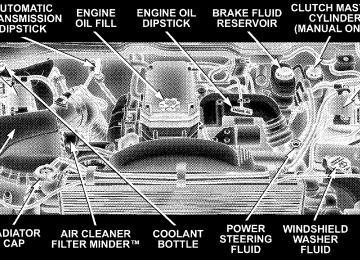
TO OPEN AND CLOSE THE HOOD
To open the hood, two latches must be released. First pull the hood release lever located below the steering wheel at the base of the instrument panel. Once the hood is released you must reach into the opening beneath the center of the grille and push up the latch to release the safety catch before raising the hood.
98 UNDERSTANDING THE FEATURES OF YOUR VEHICLE
To prevent possible damage, do not slam the hood to close it. Use a firm downward push at the front center of the hood to ensure that both latches engage.
WARNING!
If the hood is not fully latched, it could fly up when the vehicle is moving and block your forward vision. Be sure all hood latches are latched fully before driving.
LIGHTS
Interior Lights
UNDERSTANDING THE FEATURES OF YOUR VEHICLE 99
Courtesy/ dome lights are turned on when the front doors are opened, when the dimmer control (rotating wheel on the right side of the switch) is rotated to the second upward detent position, or if equipped, when the UNLOCK button is pressed on the key fob. Rotating the dimmer control to the optional fully upward position will
100 UNDERSTANDING THE FEATURES OF YOUR VEHICLE
turn on the cargo light located on the back of the cab. When a door is open and the interior lights are on, rotating the dimmer control all the way down to the OFF detent will cause all the interior lights to go out. This is also known as the 9Party9 mode because it allows the doors to stay open for extended periods of time without discharging the vehicle’s battery. The brightness of the instrument panel lighting can be regulated by rotating the dimmer control up (brighter) or down (dimmer). When the headlights are ON you can supplement the brightness of the odometer, trip odom- eter, radio and overhead console by rotating the control up until you hear a click. This feature is termed the “Parade” mode and is useful when headlights are re- quired during the day.
Battery Saver To protect the life of your vehicle’s battery, Load Shed- ding is provided for both the interior and exterior lights. If the ignition is off and any door is left ajar for 15
minutes or the dimmer control is rotated upwards for 15
minutes, the interior lights will automatically turn off. If the headlamps remain on while the ignition is cycled off, the exterior lights will automatically turn off after 5
minutes. After 5 minutes timeout, if the headlamp switch is turned off and then turned on, the exterior lights will automatically turn off after 15 minutes. If the dimmer control is rotated to the cargo lamp position with the ignition off, the cargo lamps will automatically turn off after 15 minutes. NOTE: Battery Saver mode is cancelled if the ignition is ON.Headlamp Delay — If Equipped To aid in your exit, your vehicle, if equipped, can be programmed by your dealer with a headlamp delay that will leave the headlamps on for 0, 30, 60, or 90 seconds. This delay is initiated when the ignition is turned OFF while the headlamp switch is on, and then the headlamp switch is cycled off. The headlamps will remain on for 60
seconds. Headlamp delay can be cancelled by either turning the headlamp switch ON then OFF or by turning the ignition ON. Headlights, Parking Lights, Panel LightsWhen the headlight switch is rotated to the first position, the parking lights, taillights, side marker lights, license plate light and instrument panel lights are all turned on. Rotating the headlight switch to the first position will also turn on the cab top clearance lights, flare lights, and tailgate lights if the vehicle is equipped with these lights. The headlights will turn ON when the switch is rotated to the second position. The
UNDERSTANDING THE FEATURES OF YOUR VEHICLE 101
9LAMP OUT9 indicator will be illuminated in the instru- ment cluster if a defective bulb or wiring circuit is detected for the headlamp system.
Your vehicle is equipped with plastic headlight lenses that are lighter and less susceptible to stone breakage than glass headlights.
102 UNDERSTANDING THE FEATURES OF YOUR VEHICLE
Plastic is not as scratch resistant as glass and therefore different lens cleaning procedures must be followed. To minimize the possibility of scratching the lenses and reducing light output, avoid wiping with a dry cloth. To remove road dirt, wash with a mild soap solution fol- lowed by rinsing. Do not use abrasive cleaning components, solvents, steel wool or other abrasive materials to clean the lenses. Daytime Running Lights (Canada and Fleet Vehicles Only) The headlights on your vehicle will illuminate when the engine is started. This provides a constant 9Lights ON9
condition until the ignition is turned OFF. The lights illuminate at less than normal intensity. If the parking brake is applied the Daytime Running Lights will turn off.Lights-on Reminder If the headlights, parking lights, courtesy lights or cargo lights are left on, after the ignition is turned off, a continuous chime will sound when the driver’s door is opened. Fog Lights — If Equipped The foglights are turned ON by placing the headlight rotary control in the parking light or headlight position and pulling out the headlight rotary control. The fog lights will operate only when the parking lights are ON or when the vehicle headlights are ON low beam. An indicator light located left of the switch will illuminate when the fog lights are on. The fog lights will turn off when the switch is pressed in, when the headlight switch is rotated to the OFF position or the high beam is selected.
UNDERSTANDING THE FEATURES OF YOUR VEHICLE 103
illuminated and a chime will be heard. If an indicator fails to light when the lever is moved, it would suggest that the switch or indicator lamp is defective. You can signal a lane change by moving the lever partially up or down.
CARGO LIGHT The cargo lights are turned on by rotating the dimmer control to the optional fully upward position. The cargo lights will also turn on for 30 seconds when a key fob Unlock is pressed, as part of the illuminated entry feature.
MULTIFUNCTION CONTROL LEVER The multifunction control lever is located on the left side of the steering column. Turn Signals Move the lever up or down to signal a right-hand or left-hand turn. The arrow on either side of the instrument cluster flashes to indicate the direction of the turn, and proper operation of the front and rear turn signal lights. If a defective bulb or wiring circuit is detected for the turn signal system, the arrow indicators will flash at a faster rate. Also, the 9LAMP OUT9 indicator in the instrument cluster will be
104 UNDERSTANDING THE FEATURES OF YOUR VEHICLE
Passing Light You can signal another vehicle with your headlights by partially pulling the multifunction lever toward the steer- ing wheel. This will cause the high beam headlights to turn on until the lever is released. High Beam / Low Beam Select Switch Pull the multifunction control lever fully toward the steering wheel to switch the headlights from HIGH or LOW beam.
Windshield Wipers
Intermittent Wiper System
UNDERSTANDING THE FEATURES OF YOUR VEHICLE 105
The wipers and washers are operated by a switch in the multifunction control lever. Turn the end of the handle to select the desired wiper speed.
The intermittent feature of this system was designed for use when weather conditions make a single wiping cycle, with a variable pause between cycles, desirable. For maximum delay between cycles, rotate the control knob into the upper end of the delay range.
106 UNDERSTANDING THE FEATURES OF YOUR VEHICLE
The delay interval decreases as you rotate the knob until it enters the LO continual speed position. The delay can be regulated from a maximum of about 15 seconds between cycles, to a cycle every 2 seconds. The delay intervals will double in duration when the vehicle speed is 10 mph (16 km) or less.
WARNING!
Sudden loss of visibility through the windshield could lead to an accident. You might not see other vehicles or other obstacles. To avoid sudden icing of the windshield during freezing weather, warm the windshield with defroster before and during wind- shield washer use.
Windshield Washers To use the washer, push in on the washer knob on the end of the multifunction control lever and hold while spray is desired. If the washer knob is depressed while in the delay range, the wiper will operate for several seconds after the washer knob is released. It will then resume the intermittent interval previously selected. If the washer knob is pushed, for a period greater than 1 second, while in the OFF position, the wiper will wipe approximately three wipes, after the wash knob is released. To prevent freeze-up of your windshield washer system in cold weather, select a solution or mixture that meets or exceeds the temperature range of your climate. This rating information can be found on most washer fluid containers.
TILT STEERING COLUMN To tilt the column, push down on the lever below the turn signal control and move the wheel up or down, as desired. Push the lever back up to lock the column firmly in place.
UNDERSTANDING THE FEATURES OF YOUR VEHICLE 107
WARNING!
Tilting the steering column while the vehicle is moving is dangerous. Without a stable steering col- umn, you could lose control of the vehicle and have an accident. Adjust the column only while the ve- hicle is stopped. Be sure it is locked before driving.
108 UNDERSTANDING THE FEATURES OF YOUR VEHICLE
DRIVER ADJUSTABLE PEDALS — IF EQUIPPED
Adjustment
1. Position the driver seat so that you are at least 10
inches (254 mm) away from the airbag located in the center of the steering wheel. 2. Fasten and adjust the seatbelts. 3. Move the adjustable pedal switch, located to the left of the steering column near the parking brake release, in the direction you desire to move the pedals. 4. The pedals cannot be adjusted when the vehicle is in R (Reverse) or when the Speed Control is SET.The power adjustable accelerator and brake pedals allow the driver to establish a comfortable position relative to the steering wheel and pedals.
CAUTION!
Do not place any article under the adjustable pedals or impede its ability to move as it may cause damage to the pedal controls. Pedal travel may become limited if movement is stopped by an obstruction in the adjustable pedal’s path.
ELECTRONIC SPEED CONTROL — IF EQUIPPED When engaged, this device takes over accelerator opera- tion at speeds greater than 35 mph (56 km/h). The controls are mounted on the steering wheel.
UNDERSTANDING THE FEATURES OF YOUR VEHICLE 109
To Activate Push the ON/OFF button to the ON position. An indi- cator light in the instrument cluster illuminates when the system is on.
110 UNDERSTANDING THE FEATURES OF YOUR VEHICLE
To Set At A Desired Speed When the vehicle has reached the desired speed, press and release the SET button. Release the accelerator and the vehicle will operate at the selected speed. To Deactivate A soft tap on the brake pedal, normal braking, clutch pressure while slowing the vehicle, or pressing the CAN- CEL button will deactivate speed control without erasing the memory. Pushing the ON/OFF button to the OFF position or turning off the ignition erases the memory.
WARNING!
Leaving the Speed Control ON when not in use is dangerous. You could accidentally set the system to cause it to go faster than you want. You could lose control and have an accident. Always leave the system OFF when you aren’t using it.
To Resume Speed To resume a previously set speed, push and release the RESUME button. Resume can be used at any speed above 30 mph (50 km/h).
To Vary The Speed Setting When the speed control is on, speed can be increased by pressing and holding the ACCEL button. When the button is released, a new set speed will be established. Tapping the ACCEL button once will result in a 2 mph (3km/h) speed increase. Each time the button is tapped, speed increases so that tapping the button three times will increase speed by 6 mph (10 km/h), etc. Tapping the COAST button once will result in a 1 mph (2
km/h) speed decrease. Each time the button is tapped, speed will decrease. For example, tapping the button 3
times will decrease the speed by 3 mph (5 km/h), etc. To decrease speed while the speed control is on, press and hold the COAST button. Release the button when the desired speed is reached, and the new speed will be set.UNDERSTANDING THE FEATURES OF YOUR VEHICLE 111
To Accelerate For Passing Depress the accelerator as you would normally. When the pedal is released, the vehicle will return to the set speed. NOTE: When driving uphill, at elevations above 2,000
ft. (610 meters), or when the vehicle is heavily loaded (especially when towing) the vehicle may slow below the SET speed. If the vehicle speed drops below 35 mph (56
km/h), the speed control will automatically disengage. If this happens, you can push down on the accelerator pedal to maintain the desired speed. Vehicles equipped with a 5–speed manual transmission should be operated in 4th gear under the above condi- tions.112 UNDERSTANDING THE FEATURES OF YOUR VEHICLE
Vehicles equipped with a 4–speed automatic transmis- sion may exhibit several 4-3 downshifts under the above conditions. To reduce the frequency of the downshifts and to improve vehicle performance, it is advisable to lock out overdrive by pressing the O/D OFF button located at the end of the gear shifter.
WARNING!
Speed Control can be dangerous where the system can’t maintain a constant speed. Your vehicle could go too fast for the conditions, and you could lose control. An accident could be the result. Don’t use Speed Control in heavy traffic or on roads that are winding, icy, snow-covered, or slippery.
OVERHEAD CONSOLE— IF EQUIPPED The two optional overhead consoles may consist of the following features:
† Courtesy/Reading Lights † Compass/Temperature Mini-Trip Computer † Universal Garage Door Opener — If Equipped
(CMTC) — If Equipped
UNDERSTANDING THE FEATURES OF YOUR VEHICLE 113
OVERHEAD CONSOLE WITH COMPASS/TEMPERATURE MINI-TRIP COMPUTER — IF EQUIPPED This optional overhead console consists of the following: † Courtesy Lights † Compass/Temperature Mini-Trip Computer (CMTC)
Courtesy/Reading Lights In the middle of the console are two courtesy/reading lights. Both lights illuminate as courtesy lights when a door is opened, when the dimmer control is rotated to the courtesy light position (fully upward position), or when the UNLOCK button is pressed on the Remote Keyless Entry transmitter, if so equipped. These lights are also operated individually as reading lights by pressing the recessed area of the corresponding lens. NOTE: The courtesy/reading lights will remain on until the switch is pressed a second time, so be sure they have been turned off before leaving the vehicle. If the interior lights are left on after the vehicle is turned off, they will extinguish after 15 minutes.
114 UNDERSTANDING THE FEATURES OF YOUR VEHICLE
This overhead console allows you to choose between a compass/temperature display and one of four trip con- ditions being monitored. US/M Button
RESET Button
Use this button to change the display from U.S. to metric measurement units.
Use this button to reset the following displays to zero: Average Fuel Economy Trip Odometer Elapsed time
Global Reset If the RESET button is pressed twice within 4 seconds while in any of the 3 resettable displays, the Global Reset will reset all 3 displays. Step Button
Use this button to choose or cycle through the four trip conditions.
UNDERSTANDING THE FEATURES OF YOUR VEHICLE 115
Average Fuel Economy (AVG ECO) Shows the average fuel economy since the last reset. This display mode becomes less sensitive to instantaneous changes in fuel consumption as the number of total vehicle miles since the last reset increases. It is suggested that this mode be reset periodically for general operation or when driving conditions change significantly (for example, at the end of a trip or when a trailer is connected or disconnected). Distance To Empty (DTE) Shows the estimated distance that can be travelled with the fuel remaining in the tank. The estimated distance is determined by a weighted average of the instantaneous and average fuel economy, according to the current fuel tank level. When Distance To Empty = 0, the fuel gauge pointer will initially be on the red “E” marker. At this point (fuel gauge pointer on the red “E” marker) there is reserve fuel
116 UNDERSTANDING THE FEATURES OF YOUR VEHICLE
capacity, which corresponds to approximately 8% of tank volume. This reserve capacity was put in place to prevent the likelihood of customers running out of fuel when operating at maximum load conditions in areas where there aren’t many gas stations. NOTE: The Distance To Empty will remain equal to zero, until the vehicle runs out of fuel or is refueled. Ram fuel tank volumes are as follows: † 26 gallons - 1500 short box models † 34 gallons - 1500 Quad Cab (if equipped)/2500/3500
† 35 gallons - 1500/2500/3500 long box modelsshort box models
Trip Odometer (ODO) This display shows the distance traveled since the last reset. Elapsed Time (ET) This display shows the accumulated ignition ON time since the last reset.
C/T Button
Use this button to select a readout of the outside tem- perature and one of eight compass headings that indicate the direction in which the vehicle is facing.
UNDERSTANDING THE FEATURES OF YOUR VEHICLE 117
WARNING!
Even if the display still reads a few degrees above 32°F ( 0°C), the road surface may be icy, particularly in woods or on bridges. Drive carefully under such conditions to prevent an accident and possible per- sonal injury or property damage.
Automatic Compass Calibration This compass is self-calibrating which eliminates the need to manually set the compass. When the vehicle is new, the compass may appear erratic and the CAL symbol will be displayed. After completing one 360° turn, with the vehicle traveling less than 5 mph (8 km/h), in an area free from large metal or metallic objects, the CAL symbol will turn off and the compass will function normally.
118 UNDERSTANDING THE FEATURES OF YOUR VEHICLE
Manual Compass Calibration
NOTE: To ensure proper compass calibration, make sure the compass variance is properly set before manu- ally calibrating the compass. If the compass appears erratic and the CAL symbol does not appear, you must manually put the compass into the “Calibration” mode. To Put Into a Calibration Mode Turn on the ignition and set the display to “Compass/ Temperature.” Press and hold the RESET button to change the display between VAR (compass variance) and CAL (compass calibration) modes. When the CAL sym- bol is displayed complete one 360 degree turn in an area free from large metal objects or power lines. The CAL symbol will turn off and the compass will function normally.
Compass Variance is the difference between magnetic north and geographic north. In some areas of the country, the difference between magnetic and geographic north is great enough to cause the compass to give false readings. If this occurs, the compass variance must be set according to the Compass Variance Map.
UNDERSTANDING THE FEATURES OF YOUR VEHICLE 119
To set the variance: Turn the ignition ON and set the display to “Compass/Temperature.” Press the RESET button approximately five seconds. The last variance zone number will be displayed. Press the STEP button to select the new variance zone and press the RESET button to resume normal operation. Outside Temperature Because the ambient temperature sensor is located un- derhood, engine temperature can influence the displayed temperature, therefore, temperature readings are slowly updated when the vehicle speed is below 20 mph (30
km/h) or during stop and go driving.120 UNDERSTANDING THE FEATURES OF YOUR VEHICLE
GARAGE DOOR OPENER — IF EQUIPPED The HomeLinkt Universal Transceiver replaces up to three remote controls (hand held transmitters) that oper- ate devices such as garage door openers, motorized gates, or home lighting. It triggers these devices at the push of a button. The Universal Transceiver operates off your vehicle’s battery and charging system; no batteries are needed.
For additional information on HomeLinkt, call 1–800– 355–3515, or on the internet at www.homelink.com.
WARNING!
A moving garage door can cause injury to people and pets in the path of the door. People or pets could be seriously or fatally injured. Only use this transceiver with a garage door opener that has a “stop and reverse” feature as required by federal safety stan- dards. This includes most garage door opener mod- els manufactured after 1982. Do not use a garage door opener without these safety features it could cause injury or death. Call toll-free 1–800–355–3515
or, on the Internet at www.homelink.com for safety information or assistance.Programming HomeLink
NOTE: When programming a garage door opener, it is advised to park outside the garage. It is also recom- mended that a new battery be placed in the hand-held transmitter of the device being programmed to HomeLink for quicker training and accurate transmis- sion of the radio-frequency signal. 1. Press and hold the two outer HomeLink buttons, and release only when the indicator light begins to flash (after 20 seconds). Do not hold the buttons for longer than 30
seconds and do not repeat step one to program a second and/or third hand-held transmitter to the remaining two HomeLink buttons.UNDERSTANDING THE FEATURES OF YOUR VEHICLE 121
WARNING!
Vehicle exhaust contains carbon monoxide, a danger- ous gas. Do not run the vehicle’s exhaust while training the transceiver. Exhaust gas can cause seri- ous injury or death.
122 UNDERSTANDING THE FEATURES OF YOUR VEHICLE
WARNING!
Your motorized door or gate will open and close while you are training the Universal Transceiver. Do not train the transceiver if people or pets are in the path of the door or gate. A moving door or gate can cause serious injury or death to people and pets or damage to objects.
2. Position the end of your hand-held transmitter 1-3
inches (3-8 cm) away from the HomeLink buttons while keeping the indicator light in view. 3. Simultaneously press and hold both the HomeLink button that you want to train and the hand-held trans- mitter buttons. Do not release the buttons until step 4
has been completed.NOTE: Some gate operators and garage door openers may require you to replace this Programming Step 3 with procedures noted in the 9Gate Operator/Canadian Pro- gramming9 section. 4. The HomeLink indicator light will flash slowly and then rapidly after HomeLink successfully receives the frequency signal from the hand-held transmitter. Release both buttons after the indicator light changes from the slow to the rapid flash. 5. Press and hold the just trained HomeLink button and observe the indicator light. If the indicator light stays on constantly, programming is complete and your device should activate when the HomeLink button is pressed and released. NOTE: To program the remaining two HomeLink but- tons, begin with 9Programming9 step two. Do not repeat step one.
If the indicator light blinks rapidly for two seconds and then turns to a constant light, continue with (Program- ming( steps 6-8 to complete the programming of a rolling code equipped device (most commonly a garage door opener). 6. At the garage door opener receiver (motor-head unit) in the garage, locate the 9learn9 or 9smart9 button. This can usually be found where the hanging antenna wire is attached to the motor-head unit. 7. Firmly press and release the 9learn9 or 9smart9 button. (The name and color of the button may vary by manu- facturer.) NOTE: There are 30 seconds in which to initiate step eight. 8. Return to the vehicle and firmly press, hold for two seconds and release the programmed HomeLink button. Repeat the (press/hold/release( sequence a second time,
UNDERSTANDING THE FEATURES OF YOUR VEHICLE 123
rolling code
and, depending on the brand of the garage door opener (or other rolling code equipped device), repeat this sequence a third time to complete the programming. HomeLink should now activate your equipped device. NOTE: To program the remaining two HomeLink but- tons, begin with 9Programming9 step two. Do not repeat step one. For questions or comments, please contact HomeLink at www.homelink.com or 1-800-355-3515. Canadian Programming/Gate Programming Canadian radio-frequency laws require transmitter sig- nals to 9time-out9 (or quit) after several seconds of transmission which may not be long enough for HomeLink to pick up the signal during programming. Similar to this Canadian law, some U.S. gate operators are designed to 9time-out9 in the same manner.
124 UNDERSTANDING THE FEATURES OF YOUR VEHICLE
If you live in Canada or you are having difficulties programming a gate operator by using the 9Program- ming9 procedures (regardless of where you live), replace (Programming HomeLink( step 3 with the following: If programming a garage door opener or gate NOTE: operator, it is advised to unplug the device during the 9cycling9 process to prevent possible overheating. 3. Continue to press and hold the HomeLink button while you press and release every two seconds (9cycle9) your hand-held transmitter until the frequency signal has successfully been accepted by HomeLink. (The indicator light will flash slowly and then rapidly.) Proceed with 9Programming9 step four to complete. Using HomeLink To operate, simply press and release the programmed HomeLink button. Activation will now occur for the trained device (i.e. garage door opener, gate operator, security system, entry door lock, home/office lighting,
etc.). For convenience, the hand-held transmitter of the device may also be used at any time. In the event that there are still programming difficulties or questions, contact HomeLink at: www.homelink.com or 1-800-355- 3515. Erasing HomeLink Buttons To erase programming from the three buttons (individual buttons cannot be erased but can be 9reprogrammed9 - note below), follow the step noted: † Press and hold the two outer HomeLink buttons until the indicator light begins to flash-after 20 seconds. Release both buttons. Do not hold for longer that 30
seconds. HomeLink is now in the train (or learning) mode and can be programmed at any time beginning with 9Programming9 - step 2.Reprogramming a Single HomeLink Button To program a device to HomeLink using a HomeLink button previously trained, follow these steps: 1. Press and hold the desired HomeLink button. DO NOT release the button. 2. The indicator light will begin to flash after 20 seconds. Without releasing the HomeLink button, proceed with 9Programming9 step 2
For questions or comments, contact HomeLink at: www.homelink.com or 1-800-355-3515. Security If you sell your vehicle, be sure to erase the frequencies. To erase all of the previously trained frequencies, hold down both outside buttons until the green light begins to flash.UNDERSTANDING THE FEATURES OF YOUR VEHICLE 125
This device complies with part 15 of FCC rules and with RSS-210 of Industry Canada. Operation is subject to the following conditions: † This device may not cause harmful interference. † This device must accept any interference that may be received including interference that may cause undes- ired operation.
NOTE: Changes or modifications not expressly ap- proved by the party responsible for compliance could void the user’s authority to operate the equipment. HomeLinkt is a trademark owned by Johnson Controls, Inc.
126 UNDERSTANDING THE FEATURES OF YOUR VEHICLE
ELECTRICAL POWER OUTLETS The auxiliary electrical outlet can provide power for in cab accessories designed for use with the standard “cigar lighter” plug. The outlet is located in the instrument panel below the ash receiver. A cap is attached to the outlet base indicating “Power Outlet” 12V-20A. There is an additional Power Outlet in the center console of a 40/20/40 seat (if equipped). The outlet(s) has/have a fused direct feed from the battery so it/they receive power whether the ignition is ON or OFF. All accessories connected to this/these outlet(s) should be removed or turned OFF when the vehicle is not in use to protect the battery against discharge.
CAUTION!
Electrical Outlet Use With Engine Off † Many accessories that can be plugged in draw power from the vehicle’s battery, even when not in use (i.e. cellular phones, etc.). Eventually, if plugged in long enough, the vehicle’s battery will discharge sufficiently to degrade battery life and/or prevent engine starting. † Accessories that draw higher power (i.e. coolers, vacuum cleaners, lights, etc.), will discharge the battery even more quickly. Only use these inter- mittently and with greater caution. † After the use of high power draw accessories, or long periods of the vehicle not being started (with accessories still plugged in), the vehicle must be driven a sufficient length of time to allow the generator to recharge the vehicle’s battery.
UNDERSTANDING THE FEATURES OF YOUR VEHICLE 127
CIGAR LIGHTER AND ASH RECEIVER The ash receiver is opened and closed by pushing on the front surface of the receiver and then allowing the receiver to open. The cigar lighter is located above and to the left of the ash receiver. As a child safety precaution, the lighter only operates with the ignition switch ON. It heats when pushed in and pops out automatically when ready for use. To preserve the heating element, do not hold the lighter in the heating position.
128 UNDERSTANDING THE FEATURES OF YOUR VEHICLE
CUPHOLDERS
Front Instrument Panel Cupholders — Automatic Transmission Only Your new Ram truck is equipped with dual-opening adjustable cupholders. The cupholder is opened and closed by pushing on the front surface. Each opening in the cupholder is adjustable and will hold cups and mugs of various sizes. To secure the cup, place the cup to be held into one of the cup wells and then push the cupholder arm toward the cup until it is held stable.
Cupholders with Automatic
Rear Cupholder — Quad Cab — If Equipped Quad Cab vehicles may be equipped with a rear cup- holder that consists of two cupwells for rear passenger convenience.
STORAGE
Center Storage Compartment — If Equipped
The center portion of the seat folds down to provide an armrest with unique storage compartments under the lid. Push the button on the front of the armrest to raise the cover. Inside there is a power outlet (if equipped), removable coin holder (if equipped), and two dividers to
UNDERSTANDING THE FEATURES OF YOUR VEHICLE 129
configure the storage area into compartments. For ex- ample, compartments can be configured to hold a lap-top computer, a cellular telephone, CD’s and miscellaneous items. The top of the cover provides a generous firm surface to serve as a desktop for your “mobile office.”
WARNING!
† This armrest is not a seat. Anyone seated on the armrest could be seriously injured during vehicle operation, or an accident. Only use the center seating position when the armrest is fully upright. † In an accident, the latch may open if the total weight of the items stored exceeds about 10 lbs (4.5 kg). These items could be thrown about endangering occupants of Items stored should not exceed a total of 10 lbs (4.5 kg).
the vehicle.
130 UNDERSTANDING THE FEATURES OF YOUR VEHICLE
Storage and Seats — If Equipped Located in the center of the front 40/20/40 seat cushion there is a storage compartment. Standard cab models also have storage behind the seat. The Quad Cab models provide additional storage under the rear seat. Lift the seat to access the storage compartment.
FOLD FLAT LOAD FLOOR — IF EQUIPPED
Fold Flat Load Floor — If Equipped Quad Cab models with a 60/40 rear seat, may be equipped with a folding steel load floor.
WARNING!
Do not operate the vehicle with loose items stored on the load floor. While driving or in an accident you may experience, abrupt stopping, rapid acceleration, or sharp turns. Loose objects stored on the load floor may move around with force and strike occupants, resulting in serious or fatal injury.
UNDERSTANDING THE FEATURES OF YOUR VEHICLE 131
Unfolding the Load Floor 1. Lift the 60/40 seat cushion(s) to the upward position.
132 UNDERSTANDING THE FEATURES OF YOUR VEHICLE
2. Grasp the knob on the load floor and lift the knob until the load floor unfolds into position.
3. Reverse the procedure to store the load floor.
Positioning the Load Floor for Storage Access Under the Seat 1. Lift the 60/40 seat cushion(s) to the upward position. 2. Unsnap the securing snap located at either side of the load floor. 3. Lift the load floor up to access storage under the load floor.
WARNING!
Do not drive with the load floor in the up position. When stopping fast or in an accident, the load floor could move to the down position causing serious injury.
UNDERSTANDING THE FEATURES OF YOUR VEHICLE 133
PICKUP BOX
4. Reverse the procedure to put the load floor back in the secured down position before you operate the vehicle.
The pickup box on your new Ram has many features designed for utility and convenience. If you are installing a toolbox to the front of the NOTE: pickup box, you must use Mopart toolbox brackets available from you dealer.
134 UNDERSTANDING THE FEATURES OF YOUR VEHICLE
You can carry wide building materials (sheets of ply- wood, etc.) by building a raised load floor. Place lumber across the box in the indentations provided above the wheel housings and in the bulkhead dividers to form the floor.
WARNING!
The pickup box is intended for load carrying pur- poses only, not for passengers, who should sit in seats and use seat belts.
WARNING!
† Care should always be exercised when operating a vehicle with unrestrained cargo. Vehicle speeds may need to be reduced. Severe turns or rough roads may cause shifting or bouncing of the cargo that may result in vehicle damage. If wide build- ing materials are to be frequently carried, the installation of a support is recommended. This will restrain the cargo and transfer the load to the pickup box floor. † If you wish to carry more than 600 lbs (272 kg) of material suspended above the wheelhouse, sup- ports must be installed to transfer the weight of the load to the pickup box floor or vehicle damage may result. The use of proper supports will permit loading up to the rated payload. † Unrestrained cargo may be thrown forward in an
accident causing serious or fatal injury.
There are stampings in the sheet metal on the inner side bulkheads of the box in front of and behind both wheel housings. Place wooden boards across the box from side to side to create separate load compartments in the pickup box. There are four tie-down cleats bolted to the lower sides of the pickup box that can sustain loads up to 1000 lbs (450
kg) total.SLIDE-IN CAMPERS
Camper Applications Certain truck models are not recommended for slide-in campers. To determine if your vehicle is excluded, please refer to the “Consumer Information Truck-Camper Load- ing” document available from your dealer. For safety reasons, follow all instructions in this important docu- ment.
UNDERSTANDING THE FEATURES OF YOUR VEHICLE 135
NOTE: When a cap or pickup camper is installed on a vehicle, an alternate CHMSL (Center High Mounted Stop Light) must be provided.
EASY-OFF TAILGATE To simplify mounting of a camper unit with an overhang, the tailgate can be removed quickly. If the truck is a 3500
dual rear wheel model, unplug the tailgate wire harness from under the rear of the truck and pull the harness out of the cargo box access hole. Unlatch the tailgate and remove the support cables by releasing the lock tang from the pivot, then rotate and pull away from the box. Once the cables are free, move to the right side of the tailgate hinge bracket. Raise the right side of the tailgate until the right side pivot clears the hanger bracket. Slide the entire tailgate to the right to free the left side pivot. Remove the tailgate from the vehicle entirely. Do not carry the tailgate loose in the truck pickup box.136 UNDERSTANDING THE FEATURES OF YOUR VEHICLE
NOTE: Dual rear wheel pickup models require properly spaced rear clearance lights. If such a vehicle is operated without a tailgate, suitable lights must be installed.
WARNING!
To avoid inhaling carbon monoxide, which is deadly, the exhaust system on vehicles equipped with “Cap or Slide-In Campers” should extend beyond the over- hanging camper compartment and be free of leaks.
UNDERSTANDING YOUR INSTRUMENT PANEL
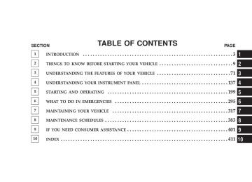
CONTENTS
m Instruments And Controls . . . . . . . . . . . . . . . . . 141
m Instrument Cluster . . . . . . . . . . . . . . . . . . . . . . 142
m Instrument Cluster Description . . . . . . . . . . . . . 143
m Electronic Digital Clock . . . . . . . . . . . . . . . . . . 151
N Clock Setting Procedure . . . . . . . . . . . . . . . . . 151m Sales Code RBB—AM/FM Stereo Radio With
Cassette Tape Player And CD Changer Capability . . . . . . . . . . . . . . . . . . . . . . . . . . . . 152
N Operating Instructions . . . . . . . . . . . . . . . . . . 152
N Power Button . . . . . . . . . . . . . . . . . . . . . . . . 152N Electronic Volume Control . . . . . . . . . . . . . . . 152
N Seek . . . . . . . . . . . . . . . . . . . . . . . . . . . . . . 153
N Tune . . . . . . . . . . . . . . . . . . . . . . . . . . . . . . 153
N To Set The Push-Button Memory . . . . . . . . . . 153
N Balance . . . . . . . . . . . . . . . . . . . . . . . . . . . . 154
N Fade . . . . . . . . . . . . . . . . . . . . . . . . . . . . . . 154
N Bass And Treble Tone Control . . . . . . . . . . . . 154
N AM/FM Selection . . . . . . . . . . . . . . . . . . . . . 154
N Mode Button . . . . . . . . . . . . . . . . . . . . . . . . 154138 UNDERSTANDING YOUR INSTRUMENT PANEL
N Cassette Player Features N CD Changer Control Capability — If
. . . . . . . . . . . . . . . . 154
Equipped . . . . . . . . . . . . . . . . . . . . . . . . . . . 156
. . . . . . . . . . . . . . . . 157N Radio Display Messages
m Sales Code RAZ—AM/ FM Stereo Radio With
Cassette Tape Player, CD Player And CD Changer Controls — If Equipped . . . . . . . . . . . 158
N Operating Instructions — Radio . . . . . . . . . . . 158
N Power Switch, Volume Control . . . . . . . . . . . . 159
N Seek Button (Radio Mode) . . . . . . . . . . . . . . . 159
N Tuning . . . . . . . . . . . . . . . . . . . . . . . . . . . . . 159
N PTY (Program Type) Button . . . . . . . . . . . . . . 159
N Balance . . . . . . . . . . . . . . . . . . . . . . . . . . . . 161
N Fade . . . . . . . . . . . . . . . . . . . . . . . . . . . . . . 161N Tone Control . . . . . . . . . . . . . . . . . . . . . . . . 161
N AM/FM Selection . . . . . . . . . . . . . . . . . . . . . 161
N Scan Button . . . . . . . . . . . . . . . . . . . . . . . . . 161
N To Set The Radio Push-Button Memory . . . . . . 162
N To Change From Clock To Radio Mode . . . . . . 162
N Operating Instructions — Tape Player . . . . . . . 162
N Seek Button . . . . . . . . . . . . . . . . . . . . . . . . . 162
N Fast Forward (FF) . . . . . . . . . . . . . . . . . . . . . 163
N Rewind (RW) . . . . . . . . . . . . . . . . . . . . . . . . 163
N Tape Eject . . . . . . . . . . . . . . . . . . . . . . . . . . . 163
N Scan Button . . . . . . . . . . . . . . . . . . . . . . . . . 163
N Changing Tape Direction . . . . . . . . . . . . . . . . 163
N Metal Tape Selection . . . . . . . . . . . . . . . . . . . 163N Pinch Roller Release . . . . . . . . . . . . . . . . . . . 164
N Noise Reduction . . . . . . . . . . . . . . . . . . . . . . 164
N Operating Instructions — CD Player . . . . . . . . 164
N Inserting The Compact Disc . . . . . . . . . . . . . . 164
N Seek Button . . . . . . . . . . . . . . . . . . . . . . . . . 165
N EJT CD (Eject) Button . . . . . . . . . . . . . . . . . . 165
N FF/Tune/RW . . . . . . . . . . . . . . . . . . . . . . . . 166
N Program Button 4 (Random Play) . . . . . . . . . . 166
N Mode . . . . . . . . . . . . . . . . . . . . . . . . . . . . . . 166
N Tape CD Button . . . . . . . . . . . . . . . . . . . . . . 166
N Time Button . . . . . . . . . . . . . . . . . . . . . . . . . 167
N Scan Button . . . . . . . . . . . . . . . . . . . . . . . . . 167UNDERSTANDING YOUR INSTRUMENT PANEL 139
N CD Changer Control Capability — If
Equipped . . . . . . . . . . . . . . . . . . . . . . . . . . . 167
m Sales Code RBK—AM/ FM Stereo Radio With
CD Player And CD Changer Controls . . . . . . . . 168
N Radio Operation . . . . . . . . . . . . . . . . . . . . . . 168
N CD Player Operation . . . . . . . . . . . . . . . . . . . 171
N CD Changer Control Capability — IfEquipped . . . . . . . . . . . . . . . . . . . . . . . . . . . 172
. . . . . . . . . . . . . . . . 174N Radio Display Messages
m Sales Code RBQ—AM/FM Stereo Radio With
6 - Disc CD Changer . . . . . . . . . . . . . . . . . . . . 175
N Radio Operation . . . . . . . . . . . . . . . . . . . . . . 175
N CD Player Operation . . . . . . . . . . . . . . . . . . . 177140 UNDERSTANDING YOUR INSTRUMENT PANEL
m Remote Sound System Controls — If Equipped . . 181
N Radio Operation . . . . . . . . . . . . . . . . . . . . . . 182
N Tape Player . . . . . . . . . . . . . . . . . . . . . . . . . 182
N CD Player . . . . . . . . . . . . . . . . . . . . . . . . . . 182
m Cassette Tape And Player Maintenance . . . . . . . 183
m Compact Disc Maintenance . . . . . . . . . . . . . . . . 184
m Radio Operation And Cellular Phones . . . . . . . . 184
m Climate Controls . . . . . . . . . . . . . . . . . . . . . . . 185N Heater Only — Fleet Vehicles . . . . . . . . . . . . . 185
N Air Conditioning—If Equipped . . . . . . . . . . . 187
N Electric Rear Window Defroster And HeatedSideview Mirrors — If Equipped . . . . . . . . . . 191
N Air Conditioning With Dual Zone Temperature
Control — If Equipped . . . . . . . . . . . . . . . . . 191
N Operating Tips . . . . . . . . . . . . . . . . . . . . . . . 196
N Operating Tips Chart . . . . . . . . . . . . . . . . . . . 198INSTRUMENTS AND CONTROLS
UNDERSTANDING YOUR INSTRUMENT PANEL 141
142 UNDERSTANDING YOUR INSTRUMENT PANEL
INSTRUMENT CLUSTER
INSTRUMENT CLUSTER DESCRIPTION
1. Malfunction Indicator Light
This light is part of an onboard diagnostic system which monitors the emissions and engine control system. If the vehicle is ready for emissions testing the light will come on when the ignition is first turned on and remain on, as a bulb check, until the engine is started. If the vehicle is not ready for emissions testing the light will come on when the ignition is first turned on and remain on for 15 seconds, then blink for 5
seconds, and remain on until the vehicle is started. If the bulb does not come on during starting, have the condi- tion investigated promptly. If this light comes on and remains on while driving, it suggests a potential engine control problem and the need for system service.UNDERSTANDING YOUR INSTRUMENT PANEL 143
Although your vehicle will usually be drivable and not need towing, see your dealer for service as soon as possible.
CAUTION!
Prolonged driving with the MIL on could cause damage to the engine control system. It also could affect fuel economy and driveability. If the MIL is flashing, severe catalytic converter damage and power loss will soon occur. Immediate service is required.
144 UNDERSTANDING YOUR INSTRUMENT PANEL
2. Voltage Gauge
When the engine is running, the gauge indicates the electrical system voltage. The pointer should stay within the normal range if the battery is charged. If the pointer moves to either extreme left or right and remains there during normal driving, the electrical sys- tem should be serviced. If the gauge pointer moves to either extreme of NOTE: the gauge, the “Check Gages” indicator will illuminate and a single chime will sound. 3. Turn Signal Indicators Lights in instrument cluster flash when outside turn signals are operating. 4. Tachometer The tachometer indicates engine speed in revolutions per minute.
CAUTION!
Do not operate the engine with the tachometer pointer at high rpm for extended periods. Engine damage may occur.
5. Airbag Indicator Light The indicator lights and remains lit for 6 to 8 seconds when the ignition is first turned on. If the light stays on, flickers or comes on while driving, have the airbag system checked by an authorized dealer. 6. High Beam Indicator
This indicator shows that headlights are on high beam.
7. Seat Belt Reminder Light
When the ignition switch is first turned ON, this light will turn on for 5 to 8 seconds as a bulb check. During the bulb check, if the driver’s seat belt is unbuckled, a chime will sound. After the bulb check or when driving, if the driver seat belt remains unbuckled, the Seat Belt Warning Light will flash or remain on continuously. Refer to 9Enhanced Driver Seat Belt Re- minder System (BeltAlert™)9 in the Occupant Restraints section for more information. 8. Speedometer The speedometer shows the vehicle speed in miles per hour and/or kilometers per hour. 9. Oil Pressure Gauge
The pointer should always indicate some oil pres- sure when the engine is running. A continuous high or low reading, under normal driving conditions, may indicate a lubrication system malfunction. Immedi- ate service should be obtained.
UNDERSTANDING YOUR INSTRUMENT PANEL 145
If the gauge pointer moves to either extreme of NOTE: the gauge, the “Check Gages” indicator will illuminate and a single chime will sound. 10. Cargo Lamp The Cargo Lamp light will illuminate when the Cargo Lamp is activated from the dimmer control switch, located next to the headlight switch. 11. Door Ajar
The Door Ajar light will illuminate when any door is opened. When the ignition is ON the Door Ajar light will stay illuminated until the open door is closed. When the ignition is OFF the Door Ajar light will stay illuminated until the open door is closed or the battery saver feature automatically turns the light off.
146 UNDERSTANDING YOUR INSTRUMENT PANEL
12. ABS Warning Light
This light monitors the Anti-Lock Brake System which is described elsewhere in this manual. This light will come on when the ignition key is turned to the ON position and may stay on for five seconds. If the ABS light remains on or comes on during driving, it indicates that the anti-lock portion of the brake system is not functioning and that service is required. See your autho- rized dealer immediately. The ABS light could also illuminate during loss of traction and remain illuminated until the brake pedal is pressed. 13. Temperature Gauge
The temperature gauge indicates engine coolant temperature. Any reading within the normal range indicates that the cooling system is operat- ing satisfactorily. The gauge needle will likely indicate a higher temperature when driving in hot weather, up mountain grades, in heavy traffic, or when towing a trailer. If the needle rises to the “245°F” mark, stop the
vehicle, shift into N (Neutral), and increase the engine idle speed for 2 to 3 minutes. If the temperature reading does not return to normal, shut your engine OFF and allow it to cool. Seek authorized service immediately. See Cooling System information in the section on “Maintain- ing Your Vehicle.”
CAUTION!
Do not leave your vehicle unattended with the engine running as you would not be able to react to the temperature indicator if the engine overheats.
NOTE: Engine idle speed will automatically increase to 1000 rpm at elevated coolant temperatures to improve engine cooling.
If the gauge pointer moves to either extreme of NOTE: the gauge, the “Check Gages” indicator will illuminate and a single chime will sound. 14. Security The light will flash rapidly for approximately 16 seconds when the vehicle theft alarm is arming. The light will flash at a slower rate after the alarm is set. The security light will also come on for about two seconds when the ignition is first turned ON. 15. Transmission Range Indicator (Automatic Tranmissions Only) When the gear selector lever is moved, this indicator shows the automatic transmission gear range selected. 16. CRUISE Light This indicator lights when the electronic speed control system is turned on.
UNDERSTANDING YOUR INSTRUMENT PANEL 147
17. Water In Fuel Indicator
Indicates there is water detected in the fuel filter bowl. Refer to the Maintenance section, Draining Fuel/Water Separator Filter, for water drain procedure.
18. Brake System Warning Light This light illuminates when the ignition key is turned to the ON position and remains on for a few seconds. If the light stays on longer, it may be an indication that the parking brake has not been released. This light will illuminate if the brake fluid is low, especially when braking or accelerating hard. This light will illuminate if the ABS indicator light has a malfunction. This light will flash if the engine is running and the parking brake is on. If the light remains on when the parking brake is released, it indicates a possible brake hydraulic system malfunction. In this case, the light will remain on until the cause is corrected.
148 UNDERSTANDING YOUR INSTRUMENT PANEL
If brake failure is indicated, immediate repair is necessary and continued operation of the vehicle in this condition is dangerous. Acceleration which causes the rear wheels to slip for a period of time may result in the red brake light illumi- nating and a brake switch code being set on ABS equipped vehicles. Depressing the brake pedal should extinguish the red brake light. 19. Wait To Start Indicator
The Wait To Start Indicator will illuminate when the ignition key is first turned to the ON position. Wait until the Wait To Start Indicator turns OFF then start the vehicle. 20. Odometer/Trip Odometer The odometer shows the total distance the vehicle has been driven.
If the odometer reading is changed during repair or replacement, be sure to keep a record of the reading before and after the service so that the correct mileage can be determined. The trip odometer shows individual trip mileage. To toggle between the odometer and the trip odometer, press the Odometer/Trip Odometer Button. To reset the Trip Odometer, press and hold the button while in trip mode, until the Trip Odometer resets. NOTE: There is also an engine hour function. This indicates the total number of hours the engine has been running. To display the engine hours perform the follow- ing: Place the ignition in RUN, but do not start the engine. With the odometer value displayed, hold the trip button down for a period of 6 seconds. The odometer will change to trip value first, then it will display the engine
hour value. The engine hours will be displayed for a period of 30 seconds until the ignition is turned off or the engine is started. 21. LAMP OUT Light The LAMP OUT indicator in the instrument cluster alerts the driver if a defective bulb or wiring circuit is detected for headlamps, turn signal lamps, and stop lamps. 22. TOW/HAUL (Automatic Transmissions Only) The TOW/HAUL button is located at the end of the gear shift lever. This light will illuminate when the TOW/ HAUL button has been selected. 23. SERV 4WD Indicator The 4WD indicator will be illuminated whenever the 4WD mode is engaged for either the manual or electric shift 4WD systems. The SERV 4WD indicator monitors the electric shift 4WD system. If the SERV 4WD light
UNDERSTANDING YOUR INSTRUMENT PANEL 149
stays on or comes on during driving, it means that the 4WD system is not functioning properly and that service is required. 24. LOW WASH Light This light comes on when the washer fluid level falls below approximately 1/4 filled. The light will remain on until fluid is added and one minute has elapsed. 25. Odometer/Trip Odometer Button Press this button to toggle between the odometer and the trip odometer display. Holding the button in resets the trip odometer reading when in trip mode. 26. Fuel Gauge Shows level of fuel in tank when ignition switch is in the ON position.
150 UNDERSTANDING YOUR INSTRUMENT PANEL
27. Low Fuel Warning Light
Glows when the pointer is between “E” and 1/8
indication mark (approximately 15% of tank vol- ume) on the fuel gauge. When the fuel gauge pointer is on “E” (equivalent to Distance To Empty [DTE] = 0 on the overhead console if so equipped) there is reserve fuel capacity, which corresponds to approxi- mately 8% of tank volume. This reserve capacity was put in place to prevent the likelihood of customers running out of fuel when operating at maximum load conditions in areas where there aren’t many gas stations. Ram fuel tank volumes are as follows: † 34 gallons - 2500/3500 short box models † 35 gallons - 2500/3500 long box models28. Transmission Oil Temperature Warning Light (Automatic Transmissions Only)
This light indicates that there is excessive trans- mission fluid temperature that might occur with severe usage such as trailer towing. If this light comes on, stop the vehicle and run the engine at idle or faster, with the transmission in NEU- TRAL until the light goes off. 29. Check Gages
This light illuminates when the Voltmeter, Engine Oil Pressure or Engine Coolant Temperature gages indicate a reading either too high or too low. Examine the gages carefully, and follow the instructions above for each indicated problem.
UNDERSTANDING YOUR INSTRUMENT PANEL 151
Clock Setting Procedure
1. Turn the ignition switch to the “ON” or “ACC” position. Using the point of a ballpoint pen or similar object, press either the “H” (Hour) or “M” (Minute) buttons on the radio. The display will show the time. 2. Press the “H” button to set hours or the “M” button to set minutes. The time setting will increase each time you press a button.
NOTE: When the ignition switch is turned to OFF, the Fuel Gage, Voltmeter, Oil Pressure and Engine Coolant Temperature gages may not show accurate readings. When the engine is not running, turn the ignition switch to ON to obtain accurate readings.
ELECTRONIC DIGITAL CLOCK
The clock and radio each use the display panel built into the radio. A digital readout shows the time in hours and minutes whenever the ignition switch is in the “ON” or “ACC” position. When the ignition switch is in the “OFF” position, or when the radio frequency is being displayed, time keep- ing is accurately maintained.
152 UNDERSTANDING YOUR INSTRUMENT PANEL
SALES CODE RBB—AM/FM STEREO RADIO WITH CASSETTE TAPE PLAYER AND CD CHANGER CAPABILITY
Operating Instructions
NOTE: Power to operate the radio is supplied through the ignition switch. It must be in the ON or ACC position to operate the radio.
NOTE: When first learning the control functions, the user should set the controls as shown in the following list. Tone Controls…As illustrated. Speaker Control…Centered. Power Button The volume control/power button pops out when pressed, this turns the sound system ON in the mode last used. Pushing the button back in turns the sound system OFF. Electronic Volume Control The electronic volume control turns continuously (360
degrees) in either direction without stopping. Turning the volume control to the right increases the volume and to the left decreases it. When the audio system is turned on, the sound will be set at the same volume level as last played.For your convenience, the volume can be turned down, but not up, when the audio system is off and the ignition is ON. Seek Press and release the SEEK button to search for the next station in either the AM or FM mode. Press the top of the button to seek up and the bottom to seek down. The radio will remain tuned to the new station until you make another selection. Holding the button will bypass stations without stopping until you release it. Tune Press the TUNE control up or down to increase or decrease the frequency. If the button is pushed and held, the radio will continue to tune until the button is released. The frequency will be displayed and continu- ously updated while the button is pushed.
UNDERSTANDING YOUR INSTRUMENT PANEL 153
To Set The Push-Button Memory When you are receiving a station that you wish to commit to push-button memory, press the SET button. The symbol SET 1 will now show in the display window. Select the “1–5” button you wish to lock onto this station and press and release that button. If a button is not selected within 5 seconds after pressing the SET button, the station will continue to play but will not be locked into push-button memory. You may add a second station to each push-button by repeating the above procedure with this exception: Press the SET button twice and SET 2 will show in the display window. Each button can be set for SET 1 and SET 2 in both AM and FM. This allows a total of 10 AM and 10 FM stations to be locked into push-button memory. The stations stored in SET 2 memory can be selected by pressing the push-button twice.
154 UNDERSTANDING YOUR INSTRUMENT PANEL
Every time a preset button is used a corresponding button number will be displayed. Balance The balance control adjusts the left-to-right speaker bal- ance. Press the BAL button in and it will pop out. Adjust the balance and push the button back in. Fade The fade control provides for balance between the front and rear speakers. Press the FADE button in and it will pop out. Adjust the balance and push the button back in. Bass and Treble Tone Control The tone controls consist of 2 separate bands. The bass band is on the left, and the treble band is on the right. Each band is adjusted by a slider control with a detent at the mid-position. Moving the control up or down in- creases or decreases amplification of that band. The mid position provides a balanced output.
AM/FM Selection Press the AM/FM button to change from AM to FM. The operating mode will be displayed next to the station frequency. The display will show ST when a stereo station is received in the FM mode. Mode Button Press the MODE button to select between the cassette tape player, CD changer, or the Satellite Radio (if equipped). When the Satellite Radio (if equipped) is selected “SA” will appear in your radio display. A CD or tape may remain in the player while in the Satellite or radio mode. Cassette Player Features With ignition OFF and the sound system OFF, you can eject the tape cassette by pushing the EJECT button.
You can turn the tape player ON by inserting a cassette or activating the MODE button (with a cassette in the radio), but only when the ignition and radio are on. Each time a cassette is inserted the tape player will begin playing on the side of the cassette that is facing up in the player. Music Search Pressing the SEEK button while playing a tape will start the Music Search mode. Press the SEEK button up for the next selection on the tape and down to return to the beginning of the current selection, or return to the beginning of the previous selection if the tape is within the first 5 seconds of the current selection. The SEEK symbol appears on the display when Music Search is in operation. Music Search shuts off automati- cally when a selection has been located.
UNDERSTANDING YOUR INSTRUMENT PANEL 155
Selective Music Search Press the SEEK button up or down to move the track number to skip forward or backward 1 to 7 selections. Press the SEEK button once to move 1 selection, twice to move 2 selections, etc. Fast Forward And Rewind Buttons Pressing the TUNE button up or down momentarily activates Fast Forward or Rewind and makes the direc- tional arrows appear on the display. To stop Fast Forward or Rewind, press the TUNE button again. Time Button Press the time button to toggle between station frequency and time of day. Pressing this button while playing a cassette tape will change the side of the tape being played.
156 UNDERSTANDING YOUR INSTRUMENT PANEL
NR (Noise Reduction) Pushing the Number 2 Pre-set button when a tape is playing deactivates the Dolby Noise Reduction System*. When Dolby is ON, the NR symbol appears on the display. Each time a tape is inserted the Dolby will turn ON. * “Dolby” noise reduction manufactured under license from Dolby Laboratories Licensing Corporation. Dolby and the double-D symbol are trademarks of Dolby Labo- ratories Licensing Corporation. CD Changer Control Capability — If Equipped This radio is compatible with a remote mounted CD changer available through Mopar Accessories. The fol- lowing instructions are for the radio controls that operate this CD changer. Mode Button To activate the CD changer, press the MODE button until CD information appears on the display.
Push-Button While the CD changer is playing, press the NUMBER 1
push-button or the NUMBER 5 push-button to select a disc numbered higher or lower than the one currently being played. Seek Button Press the SEEK up or down to select another track on the same disc. A SEEK symbol will appear on the display. Fast Forward And Rewind Buttons Press and hold the FF button for fast forward. Press and hold the RW button for fast reverse. The audio output can be heard when fast forward and fast reverse are activated. Random Play (RND) Press the Random button to play the tracks on the selected disc in random order for an interesting change of pace.Random can be cancelled by pressing the button a second time or by ejecting the CD from the changer. CD Diagnostic Indicators When driving over a very rough road, the CD player may skip momentarily. Skipping will not damage the disc or the player, and play will resume automatically. As a safeguard and to protect your CD player, one of the following warning symbols may appear on your display. A CD HOT symbol indicates the player is too hot. CD HOT will pause the operation. Play can be resumed when the operating temperature is corrected or another MODE is selected.
UNDERSTANDING YOUR INSTRUMENT PANEL 157
An ERR symbol will appear on the display if the laser is unable to read the Disc data for the following reasons: † Excessive vibration † Disc inserted upside down † Damaged disc † Water condensation on optics Radio Display Messages Your radio has been designed to display certain messages when a problem is detected with the CD player.
158 UNDERSTANDING YOUR INSTRUMENT PANEL
SALES CODE RAZ—AM/ FM STEREO RADIO WITH CASSETTE TAPE PLAYER, CD PLAYER AND CD CHANGER CONTROLS — IF EQUIPPED
Operating Instructions — Radio
NOTE: Power to operate the radio is controlled by the ignition switch. It must be in the ON or ACC position to operate the radio.
Power Switch, Volume Control Press the ON/VOL control to turn the radio on. Turn the volume control clockwise to increase the volume. The volume will be displayed and continuously updated while the button is pressed. Seek Button (Radio Mode) Press and release the Seek button to search for the next station in either the AM or FM mode. Press the top of the button to seek up and the bottom to seek down. Holding the button will by pass stations until you release the button. Tuning Press the TUNE control up or down to increase or decrease the frequency. If you press and hold the button, the radio will continue to tune until you release the button. The frequency will be displayed and continu- ously updated while the button is pressed.
UNDERSTANDING YOUR INSTRUMENT PANEL 159
PTY (Program Type) Button Pressing this button once will turn on the PTY mode for 5 seconds. If no action is taken during the 5 second time out the PTY icon will turn off. Pressing the PTY button within 5 seconds will allow the program format type to be selected. Many radio stations do not currently broad- cast PTY information. Toggle the PTY button to select the following format types:
Program Type
Radio Display
Adult Hits Classical Classic Rock College Country Information Jazz Foreign Language
Adlt Hit Classicl Cls Rock College Country Inform Jazz Language
160 UNDERSTANDING YOUR INSTRUMENT PANEL
Program Type
News Nostalgia Oldies Personality Public Rhythm and Blues Religious Music Religious Talk Rock Soft Soft Rock Soft Rhythm and Blues Sports Talk Top 40
WeatherRadio Display
News Nostalga Oldies Persnlty Public R & B Rel Musc Rel Talk Rock Soft Soft Rck Soft R&B Sports Talk Top 40
WeatherBy pressing the SEEK button when the PTY icon is displayed, the radio will be tuned to the next frequency station with the same selected PTY name. The PTY function only operates when in the FM mode. The radio display will flash “SEEK” and the selected PTY program type when searching for the next PTY station. If no station is found with the selected PTY program type, the radio will return to the last preset station. If a preset button is activated while in the PTY (Program Type) mode, the PTY mode will be exited and the radio will tune to the preset station. Pressing PTY, then SCAN will scan the FM Band and stop at all RDS stations. Each RDS station will be played for a 5 second scan once around the FM Band and stop at the last station. The PTY icon will then turn off.
Balance The Balance control adjusts the left-to-right speaker bal- ance. Push in the button and it will pop out. Adjust the balance and push the button back in. The balance will be displayed and continuously updated while the button is turned. Fade The Fade control provides for balance between the front and rear speakers. Push in the button and it will pop out. Adjust the balance and push the button back in. The fade will be displayed and continuously updated while the button is turned. Tone Control Slide the Bass and/or Treble controls up or down to adjust the sound for the desired tone. The treble, and bass will be displayed and continuously updated while the slide is moved.
UNDERSTANDING YOUR INSTRUMENT PANEL 161
AM/FM Selection Press the AM/FM button to change from AM to FM. The operating mode will be displayed next to the station frequency. The display will show ST when a stereo station is received. Scan Button Pressing the SCAN button causes the tuner to search for the next station, in either AM or FM, pausing for 5
seconds at each listenable station before continuing to the next. Pressing the AM/FM button continues the search in the alternate frequency band. To stop the search, press SCAN a second time.162 UNDERSTANDING YOUR INSTRUMENT PANEL
To Set The Radio Push-button Memory When you are receiving a station that you wish to commit to push-button memory, press the SET button. SET 1 will show in the display window. Select the push-button you wish to lock onto this station and press and release that button. If a station is not selected within 5 seconds after pressing the SET button, the station will continue to play but will not be locked into push-button memory. You may add a second station to each push-button by repeating the above procedure with this exception: Press the SET button twice and SET 2 will show in the display window. Each button can be set for SET 1 and SET 2 in both AM and FM. This allows a total of 10 AM and 10 FM stations to be locked into memory. You can recall the stations stored in SET 2 memory by pressing the push- button twice.
To Change From Clock To Radio Mode Press the Time button to change the display between radio frequency and time. Operating Instructions — Tape Player Insert the cassette with the exposed tape side toward the right and the mechanical action of the player will gently pull the cassette into the play position. NOTE: When subjected to extremely cold temperatures, the tape mechanism may require a few minutes to warm up for proper operation. Sometimes poor playback may be experienced due to a defective cassette tape. Clean and demagnetize the tape heads at least twice a year. Seek Button Press the SEEK button up for the next selection on the tape and down to return to the beginning of the current selection.
Press the SEEK button up or down to move the track number to skip forward or backward 1 to 6 selections. Press the SEEK button once to move 1 selection, twice to move 2 selections, etc. Fast Forward (FF) Press the FF button up momentarily to advance the tape in the direction that it is playing. The tape will advance until the button is pressed again or the end of the tape is reached. At the end of the tape, the tape will play in the opposite direction. Rewind (RW) Press the RW button momentarily to reverse the tape direction. The tape will reverse until the button is pressed again or until the end of the tape is reached. At the end of the tape, the tape will play in the opposite direction.
UNDERSTANDING YOUR INSTRUMENT PANEL 163
Tape Eject Press the EJT Tape button and the cassette will disengage and eject from the radio. Scan Button Press this button to play 10 seconds of each selection. Press the scan button a second time to cancel the feature. Changing Tape Direction If you wish to change the direction of tape travel (side being played), press the PTY button. The lighted arrow in the display window will show the new direction. Metal Tape Selection If a standard metal tape is inserted into the player, the player will automatically select the correct equalization and the 70 symbol will appear in the display window.
164 UNDERSTANDING YOUR INSTRUMENT PANEL
Pinch Roller Release If ignition power or the radio ON/OFF switch are turned off, the pinch roller will automatically retract to protect the tape from any damage. When power is restored to the tape player, the pinch roller will automatically reengage and the tape will resume play. Noise Reduction The Dolby Noise Reduction System* is on whenever the tape player is on, but may be switched off. To turn off the Dolby Noise reduction System: Press the Dolby button (button 2) after you insert the tape. The NR light in the display will go off when the Dolby System is off. The Dolby System is automatically reactivated each time a tape is inserted. * ”Dolby” noise reduction manufactured under license from Dolby Laboratories Licensing Corporation. Dolby and the double-D symbol are trademarks of Dolby Labo- ratories Licensing Corporation.
Operating Instructions — CD Player
NOTE: The ignition switch must be in the ON or ACC position and the volume control ON before the CD player will operate.
CAUTION!
This CD player will accept 4 3⁄4 inch (12 cm) discs only. The use of other sized discs may damage the CD player mechanism.
Inserting The Compact Disc The CD player contained within the radio is not a multi-disc changer, and will only accept one CD. Gently insert one CD into the CD player with the CD label facing up. The CD will automatically be pulled into the CD Player.
If the volume control is ON, the unit will switch from radio to CD mode and begin to play. The display will show the track number and index time in minutes and seconds. Play will begin at the start of track one. NOTE: † You may eject a disc with the radio OFF. The ignition switch must be in the ON or ACC position to insert a disc with the radio OFF. † If you insert a disc with the ignition ON and the radio OFF, the CD will automatically be pulled into the CD Player and the display will show the time of day. If you insert a disc with the ignition OFF, the display will show the time of day for about 5 seconds, then go out.
UNDERSTANDING YOUR INSTRUMENT PANEL 165
Seek Button Press the top of the SEEK button for the next selection on the CD. Press the bottom of the button to return to the beginning of the current selection, or return to the beginning of the previous selection if the CD is within the first 10 seconds of the current selection. EJT CD (Eject) Button Press this button and the disc will unload and move to the entrance for easy removal. The unit will switch to the radio mode. If you do not remove the disc within 15 seconds, it will be reloaded. The radio mode will continue to appear. The disc can be ejected with the radio OFF.
166 UNDERSTANDING YOUR INSTRUMENT PANEL
FF/TUNE/RW Press FF (Fast Forward) and the CD player will begin to fast forward until FF is released. The RW ( Reverse) button works in a similar manner. Program Button 4 (Random Play) Press this button while the CD is playing to activate Random Play. This feature plays the tracks on the se- lected disc in random order to provide an interesting change of pace. Press the SEEK button to move to the next randomly selected track. Press TUNE FF to fast forward through the tracks. Press