- 2009 Dodge RAM Diesel Owners Manuals
- Dodge RAM Diesel Owners Manuals
- 2010 Dodge RAM Diesel Owners Manuals
- Dodge RAM Diesel Owners Manuals
- 2005 Dodge RAM Diesel Owners Manuals
- Dodge RAM Diesel Owners Manuals
- 2006 Dodge RAM Diesel Owners Manuals
- Dodge RAM Diesel Owners Manuals
- 2008 Dodge RAM Diesel Owners Manuals
- Dodge RAM Diesel Owners Manuals
- 2004 Dodge RAM Diesel Owners Manuals
- Dodge RAM Diesel Owners Manuals
- 2007 Dodge RAM Diesel Owners Manuals
- Dodge RAM Diesel Owners Manuals
- Download PDF Manual
-
—This symbol certifies that the tire is in compliance with the U.S. Department of Transportation tire safety standards, and is approved for highway use.
EXAMPLE:
DOT MA L9 ABCD 0301
MA = Code representing the tire manufacturing location.(2 digits) L9 = Code representing the tire size.(2 digits) ABCD = Code used by tire manufacturer.(1 to 4 digits) 03 = Number representing the week in which the tire was manufactured.(2 digits)
—03 means the 3rd week.
01 = Number representing the year in which the tire was manufactured.(2 digits)
—01 means the year 2001. —Prior to July 2000, tire manufacturers were only required to have 1 number to represent the year in which the tire was manufactured. Example: 031 could represent the 3rd week of 1981 or 1991.
Tire Loading and Tire Pressure
Tire and Loading Information Placard
STARTING AND OPERATING 247
Tire Placard Location NOTE: Some vehicles have a “Tire and Loading Infor- mation” placard located on the driver’s side “B” pillar.
This placard tells you important information about the, 1) number of people that can be carried in the vehicle 2) the total weight your vehicle can carry 3) the tire size designed for your vehicle 4) the cold tire inflation pressures for the front, rear and spare tires.
248 STARTING AND OPERATING
Loading The vehicle maximum load on the tire must not exceed the load carrying capacity of the tire on your vehicle. You will not exceed the tire’s load carrying capacity if you adhere to the loading conditions, tire size and cold tire inflation pressures specified on the Tire and Loading Information placard and the Vehicle Loading section of this manual. NOTE: Under a maximum loaded vehicle condition, gross axle weight ratings (GAWR’s) for the front and rear axles must not be exceeded. For further information on GAWR’s, vehicle loading and trailer towing, see the Vehicle Loading section of this manual. To determine the maximum loading conditions of your vehicle, locate the statement “The combined weight of occupants and cargo should never exceed XXX kg or XXX lbs.” on the Tire and Loading Information placard. The
combined weight of occupants, cargo/luggage and trailer tongue weight (if applicable) should never exceed the weight referenced here. Steps for Determining Correct Load Limit 1. Locate the statement “The combined weight of occu- pants and cargo should never exceed XXX pounds” on your vehicle’s placard. 2. Determine the combined weight of the driver and passengers that will be riding in your vehicle. 3. Subtract the combined weight of the driver and pas- sengers from XXX kilograms or XXX pounds. 4. The resulting figure equals the available amount of cargo and luggage load capacity. For example, if “XXX” amount equals 1400 lbs. and there will be five 150 lb. passengers in your vehicle, the amount of available cargo and luggage load capacity is 650 lb. (1400–750 (5 x 150) = 650 lb.)
5. Determine the combined weight of luggage and cargo being loaded on the vehicle. That weight may not safely exceed the available cargo and luggage load capacity calculated in step 4. 6. If your vehicle will be towing a trailer, load from your trailer will be transferred to your vehicle. Consult this manual to determine how this reduces the available cargo and luggage load capacity of your vehicle.
STARTING AND OPERATING 249
NOTE: The following table shows examples on how to calculate total load, cargo/luggage and towing capacities of your vehicle with varying seating configurations and number and size of occupants. This table is for illustra- tion purposes only and may not be accurate for the seating and load carry capacity of your vehicle. NOTE: For the following example the combined weight of occupants and cargo should never exceed 865 lbs. (392
Kg).250 STARTING AND OPERATING
WARNING!
1. Safety—
STARTING AND OPERATING 251
Overloading of your tire is dangerous. Overloading can cause tire failure, affect vehicle handling, and increase your stopping distance. Use tires of the recommended load capacity for your vehicle. Never overload them.
TIRES—GENERAL INFORMATION
Tire Pressure Proper tire inflation pressure is essential to the safe and satisfactory operation of your vehicle. Three primary areas are affected by improper tire pressure:
WARNING!
Improperly inflated tires are dangerous and can cause accidents. † Under inflation increases tire flexing and can result in tire failure. † Over inflation reduces a tire’s ability to cushion shock. Objects on the road and chuck holes can cause damage that results in tire failure. † Unequal tire pressures can cause steering prob- lems. You could lose control of your vehicle. † Over inflated or under inflated tires can affect vehicle handling and can fail suddenly, resulting in loss of vehicle control. † Unequal tire pressures from one side of the vehicle to the other can cause the vehicle to drift to the right or left. Always drive with each tire inflated to the recom- mended cold tire inflation pressure.
252 STARTING AND OPERATING
2. Economy— Improper inflation pressures can cause uneven wear patterns to develop across the tire tread. These abnormal wear patterns will reduce tread life resulting in a need for earlier tire replacement. Underinflation also increases tire rolling resistance and results in higher fuel consumption. 3. Ride Comfort and Vehicle Stability— Proper tire inflation contributes to a comfortable ride. Overinflation produces a jarring and uncomfortable ride. Tire Inflation Pressures The proper cold tire inflation pressure for passenger cars is listed on either the face of the driver’s door or the driver’s side “B” pillar. For vehicles other than passenger cars, the cold tire inflation pressures are listed on either the “B” pillar, the Certification Label or in the Tire Inflation Pressures brochure in the glove compartment. Some vehicles may have Supplemental Tire Pressure Information for vehicle loads that are less than the
maximum loaded vehicle condition. These pressure con- ditions will be found in the “Supplemental Tire Pressure Information” section of this manual.
“B” PILLAR
The pressure should be checked and adjusted as well as inspecting for signs of tire wear or visible damage at least once a month. Use a good quality pocket-type gauge to
check tire pressure. Do not make a visual judgement when determining proper inflation. Radial tires may look properly inflated even when they are underinflated.
CAUTION!
After inspecting or adjusting the tire pressure al- ways reinstall the valve stem cap–if equipped. This will prevent moisture and dirt from entering the valve stem, which could damage the valve stem.
Inflation pressures specified on the placard are always “cold tire inflation pressure”. Cold tire inflation pressure is defined as the tire pressure after the vehicle has not been driven for at least 3 hours, or driven less than 1mile (1 km) after a 3 hour period. The cold tire inflation pressure must not exceed the maximum inflation pres- sure molded into the tire side wall.
STARTING AND OPERATING 253
Check tire pressures more often if subject to a wide range of outdoor temperatures, as tire pressures vary with temperature changes. Tire pressures change by approximately 1 psi (7 kPa) per 12° F (7° C) of air temperature change. Keep this in mind when checking tire pressure inside a garage especially in the winter. Example: If garage temperature = 68° F (20° C) and the outside temperature = 32° F (0° C) then the cold tire inflation pressure should be increased by 3 psi (21 kPa), which equals 1 psi (7 kPa) for every 12° F (7° C) for this outside temperature condition. Tire pressure may increase from 2 to 6 psi (13 to 40 kPa) during operation. DO NOT reduce this normal pressure build up or your tire pressure will be too low.
254 STARTING AND OPERATING
Tire Pressures for High Speed Operation The manufacturer advocates driving at safe speeds within posted speed limits. Where speed limits or condi- tions are such that the vehicle can be driven at high speeds, maintaining correct tire inflation pressure is very important. Increased tire pressure and reduced vehicle loading may be required for high speed vehicle opera- tion. Refer to original equipment or an authorized tire dealer for recommended safe operating speeds, loading and cold tire inflation pressures.
WARNING!
High speed driving with your vehicle under maxi- mum load is dangerous. The added strain on your tires could cause them to fail. You could have a serious accident. Don’t drive a vehicle loaded to the maximum capacity at continuous speeds above 75
mph (120 km/h).Radial-Ply Tires
WARNING!
Combining radial ply tires with other types of tires on your vehicle will cause your vehicle to handle poorly. The instability could cause an accident. Al- ways use radial ply tires in sets of four (or 6, in case of trucks with dual rear wheels). Never combine them with other types of tires.
Cuts and punctures in radial tires are repairable only in the tread area because of sidewall flexing. Consult your authorized tire dealer for radial tire repairs.
STARTING AND OPERATING 255
Compact Spare Tire — If Equipped The compact spare is for temporary emergency use with radial tires. It is engineered to be used on your style vehicle only. Since this tire has limited tread life, the original tire should be repaired (or replaced) and rein- stalled at the first opportunity.
WARNING!
Temporary use spare tires are for emergency use only. With these tires, do not drive more than 50 mph (80 km/h). Temporary-use spare tires have limited tread life. When two or more tread wear indicators appear in adjacent grooves, the temporary use spare tire needs to be replaced. Be sure to follow the warnings which apply to your spare. Failure to do so could result in spare tire failure and loss of vehicle control.
256 STARTING AND OPERATING
Do not install a wheel cover or attempt to mount a conventional tire on the compact spare wheel, since the wheel is designed specifically for the compact spare. Do not install more than one compact spare tire/wheel on the vehicle at any given time.
Tire Spinning When stuck in mud, sand, snow, or ice conditions, do not spin your vehicle’s wheels above 35 mph (55 km/h). See the paragraph on Freeing A Stuck Vehicle in Section 6 of this manual.
CAUTION!
WARNING!
Because of the reduced ground clearance, do not take your vehicle through an automatic car wash with the compact spare installed. Damage to the vehicle may result.
Fast spinning tires can be dangerous. Forces gener- ated by excessive wheel speeds may cause tire dam- age or failure. A tire could explode and injure someone. Do not spin your vehicle’s wheels faster than 35 mph (55 km/h) when you are stuck. And don’t let anyone near a spinning wheel, no matter what the speed.
Tread Wear Indicators Tread wear indicators are in the original equipment tires to help you in determining when your tires should be replaced.
These indicators are molded into the bottom of the tread grooves and will appear as bands when the tread depth becomes 1/16 inch (2 mm). When the indicators appear in 2 or more adjacent grooves, the tire should be replaced.
STARTING AND OPERATING 257
Many states have laws requiring tire replacement at this point. Replacement Tires The tires on your new vehicle provide a balance of many characteristics. They should be inspected regularly for wear and correct cold tire inflation pressure. The manu- facturer strongly recommends that you use tires equiva- lent to the originals in size, quality and performance when replacement is needed (see the paragraph on tread wear indicators). Refer to the Tire and Loading Informa- tion placard for the size designation of your tire. The service description and load identification will be found on the original equipment tire. Failure to use equivalent replacement tires may adversely affect the safety, han- dling, and ride of your vehicle. We recommend that you contact your original equipment or an authorized tire dealer with any questions you may have on tire specifi- cations or capability.
258 STARTING AND OPERATING
WARNING!
† Do not use a tire, wheel size or rating other than that specified for your vehicle. Some combina- tions of unapproved tires and wheels may change suspension dimensions and performance charac- teristics, resulting in changes to steering, han- dling, and braking of your vehicle. This can cause unpredictable handling and stress to steering and suspension components. You could lose control and have an accident resulting in serious injury or death. Use only the tire and wheel sizes with load ratings approved for your vehicle. † Never use a tire with a smaller load index or capacity, other than what was originally equipped on your vehicle. Using a tire with a smaller load index could result in tire overloading and failure. You could lose control and have an accident. † Failure to equip your vehicle with tires having adequate speed capability can result in sudden tire failure and loss of vehicle control.
CAUTION!
Replacing original tires with tires of a different size may result in false speedometer and odometer read- ings.
Alignment And Balance Poor suspension alignment may result in: † Fast tire wear. † Uneven tire wear, such as feathering and one-sided † Vehicle pull to right or left. Tires may also cause the vehicle to pull to the left or right. Alignment will not correct this condition. See your dealer for proper diagnosis.
wear.
Improper alignment will not cause vehicle vibration. Vibration may be a result of tire and wheel out-of- balance. Proper balancing will reduce vibration and avoid tire cupping and spotty wear.
SUPPLEMENTAL TIRE PRESSURE INFORMATION A light load vehicle condition is defined as two passen- gers {150 lbs (68 kg) each} plus 200 lbs (91kg) of cargo. Cold tire inflation pressures for a lightly loaded vehicle will be found on a “Supplemental Tire Pressure Inflation” label located on the face of the driver’s door or in the Tire Information Pressures pamphlet in the glove box.
TIRE CHAINS Use “Class U” chains on 2500/3500 Ram Trucks, or other traction aids that meet SAE Type “U” specifications. NOTE: Chains must be the proper size for the vehicle, as recommended by the chain manufacturer.
STARTING AND OPERATING 259
CAUTION!
To avoid damage to your vehicle, tires or chains, observe the following precautions:
† Because of limited chain clearance between tires and other
suspension components, it is important that only chains in good condition are used. Broken chains can cause serious vehicle damage. Stop the vehicle immediately if noise occurs that could suggest chain breakage. Remove the damaged parts of the chain before further use.
after driving about 1/2 mile (0.8 km).
† Install chains as tightly as possible and then retighten † Do not exceed 45 mph (72 km/h). † Drive cautiously and avoid severe turns and large † Do not install tire chains on front wheels of 4x2 vehicles. † Do not drive for a prolonged period on dry pavement. † Observe the tire chain manufacturer’s instructions on
bumps, especially with a loaded vehicle.
method of installation, operating speed, and conditions for usage. Always use the lower suggested operating speed of the chain manufacturer if different than the speed recommended by the manufacturer.
260 STARTING AND OPERATING
These cautions apply to all chain traction devices, includ- ing link and cable (radial) chains. Tire chain use is permitted only on the rear tires of Ram 4X2 trucks. NOTE: The use of class “U” chains is permitted on the front and rear of 4X4, 2500 Ram Trucks with LT245/ 70R17E tires. NOTE: The use of class “U” chains is permitted on the front and rear of 4X4, 3500 Ram Trucks with Dual Rear Wheels and LT235/80R17E tires. NOTE: On 4X2 2500/3500 Ram Trucks, class “U” snow chains are permitted on the rear wheels only of vehicles equipped with LT245/70R17, LT265/70R17, and LT235/ 80R17 size tires.
NOTE: On 4X4 2500/3500 Single Rear Wheel (SRW) Ram Trucks, class “U” snow chains are permitted on the rear wheels only of vehicles equipped with LT265/70R17.
CAUTION!
Do not use tire chains on 4x4 Ram trucks equipped with P265/70R17, LT275/70R17 tires. There may not be adequate clearance for the chains and you are risking structural or body damage to your vehicle. Do not use tire chains on the 4X2 front wheels of 2500/3500 SRW (Single Rear Wheels) equipped with LT245/70R17, LT265/70R17 tires or 4X4 front tires of Ram Trucks equipped with LT265/70R17tires. There may not be adequate clearance for the chains and you are risking structural or body damage to your vehicle.
SNOW TIRES Snow tires should be of the same size and type construc- tion as the front tires. Consult the manufacturer of the snow tire to determine any maximum vehicle speed requirement associated with the tire. These tires should always be operated at the vehicle maximum capacity inflation pressures under any load condition. While studded tires improve performance on ice, skid and traction capability on wet or dry surfaces may be poorer than that of non-studded tires. Some states pro- hibit studded tires; local laws should be checked before using these tire types.
therefore,
STARTING AND OPERATING 261
TIRE ROTATION RECOMMENDATIONS Tires on the front and rear axles of vehicles operate at different loads and perform different steering, driving, and braking functions. For these reasons, they wear at unequal rates, and develop irregular wear patterns. These effects can be reduced by timely rotation of tires. The benefits of rotation are especially worthwhile with aggressive tread designs such as those on On/Off Road type tires. Rotation will increase tread life, help to main- tain mud, snow, and wet traction levels, and contribute to a smooth, quiet ride.
262 STARTING AND OPERATING
Follow the recommended tire rotation frequency for your type of driving found in the “Maintenance Schedules” Section of this manual. More frequent rotation is permis- sible if desired. The reasons for any rapid or unusual wear should be corrected prior to rotation being per- formed.
NOTE: On Canadian vehicles only, if your Ram truck is equipped with All-Season type tires on the front and ON/OFF Road type tires mounted on the rear, do not use a front to back rotation pattern. Instead, rotate your tires side to side at the recommended intervals.
Dual Rear Wheels
The tires used on dual wheel assemblies should be matched for wear to prevent overloading one tire in a set. To check if tires are even, lay a straight edge across all four tires. The straight edge should touch all the tires.
STARTING AND OPERATING 263
CAUTION!
3500 Dual Rear Tires have only one approved direc- tion of rotation. This is to accommodate the asym- metrical design (tread pattern) of the ON/OFF road tire and the use of Outline White Letter (OWL) tires. † When replacing a flat, the spare tire may have to be remounted on the rim or installed at a different location to maintain the correct placement of the tire on the wheel relative to the tire/wheel posi- tion on the truck. For example, if the spare is used to replace an outer rear tire it will have to be remounted on the rim so that the wheel is dished inward. That way the tread design of asymmetri- cal tires and the white writing of the OWL tires will maintain proper position.
264 STARTING AND OPERATING
ENGINE RUNAWAY
WARNING!
In case of engine runaway due to flammable fumes from gasoline spills or turbocharger oil leaks being sucked into the engine do the following to help avoid personal injury and/or vehicle damage: 1. Shut off engine ignition switch. 2. Using a CO2 or dry chemical type fire extin- guisher, direct the spray from the fire extinguisher into the grille on the passenger side so that the spray enters the engine air intake.
FUEL REQUIREMENTS Use good quality diesel fuel from a reputable supplier in your Dodge truck. For most year-round service, No. 2
diesel fuel meeting ASTM specification D-975 will pro- vide good performance. If the vehicle is exposed to extreme cold (below 20°F or -7°C), or is required to operate at colder-than-normal conditions for prolonged periods, use climatized No. 2 diesel fuel or dilute the No. 2 diesel fuel with 50% No. 1 diesel fuel. This will provide better protection from fuel gelling or wax-plugging of the fuel filters.WARNING!
The inlet for the engine air intake is located behind the passenger side headlamp and receives air through the grille
Do not use alcohol or gasoline as a fuel blending agent. They can be unstable under certain conditions and hazardous or explosive when mixed with diesel fuel.
Diesel fuel is seldom completely free of water. To prevent fuel system trouble, drain the accumulated water from the fuel/water separator using the fuel/water separator drain provided. If you buy good quality fuel and follow the cold weather advice above, fuel conditioners should not be required in your vehicle. If available in your area, a high cetane “premium” diesel fuel may offer improved cold-starting and warm-up performance. ADDING FUEL
CAUTION!
To avoid fuel spillage and overfilling, do not “top off” the fuel tank after filling.
NOTE: † When the fuel nozzle “clicks” or shuts off, the fuel
tank is full.
STARTING AND OPERATING 265
† Tighten the gas cap until you hear a “clicking” sound. This is an indication that the gas cap is properly tightened. † Make sure that the gas cap is tightened each time the
vehicle is refueled.
WARNING!
A fire may result if fuel is pumped into a container that is inside of a vehicle or in the bed or on the opened tailgate. Always place fuel containers on the ground while filling.
Fuel Filler Cap (Gas Cap) The gas cap is behind the fuel filler door. If the gas cap is lost or damaged, be sure the replacement cap is for use with this vehicle.
266 STARTING AND OPERATING
CAUTION!
Damage to the fuel system or emission control system could result from using an improper fuel tank filler tube cap (gas cap). A poorly fitting cap could let impurities into the fuel system.
WARNING!
† Remove the fuel tank filler tube cap (gas cap) slowly to prevent fuel spray from the filler neck which may cause injury. † The volatility of some fuels may cause a buildup of pressure in the fuel tank that may increase while you drive. This pressure can result in a spray of fuel and/or vapors when the cap is removed from a hot vehicle. Removing the cap slowly allows the pressure to vent and prevents fuel spray. † Never have any smoking materials lit in or near the vehicle when the gas cap is removed or the tank filled. † Never add fuel to the vehicle when the engine is
running.
Avoid Using Contaminated Fuel Fuel that is contaminated by water or dirt can cause severe damage to the engine fuel system which is not covered by the warranty. Proper maintenance of the engine fuel filter and fuel tank is essential. (See Section 7
for Maintenance Procedures). NOTE: Climatized diesel fuel is a blend of Number 2
and Number 1 Diesel fuel which reduces the temperature at which wax crystals form in the fuel. Bulk Fuel Storage If you store quantities of fuel, good maintenance of the stored fuel is also essential. Fuel contaminated with water will promote the growth of “microbes.” These microbes form “slime” that will clog fuel filters and lines. Drain condensation from the supply tank and change the line filter on a regular basis.STARTING AND OPERATING 267
Fuel Specifications The Cummins Turbocharged, Charge Air Cooled, Diesel engine has been developed to take advantage of the high energy content and generally lower cost No. 2 diesel fuel or No. 2 climatized diesel fuels. Experience has shown that it also operates on No. 1 diesel fuels or other fuels within the specifications in the following chart. NOTE: As sufficient testing has not been completed, organically blended diesel fuels (e.g. biodiesel, ethanol, and methanol blends) are not recommended or approved for use with your Cummins Diesel equipped Dodge Ram Truck. In addition, commercially available fuel addi- NOTE: tives are not necessary for the proper operation of your Cummins Diesel equipped Dodge Ram Truck. NOTE: No. 1 diesel fuel should only be used where extended arctic conditions (-10°F or 23°C) exist.
268 STARTING AND OPERATING
Number 2 Diesel Fuel Specifications Fuel Properties - No. 2 - Diesel Reference Viscosity - 1.9to 4.1 centistokes Cetane Number - 40 min. Sulfur Content -.05% by weight Water & Sediment - less than 0.05 % by volume Carbon Residue - Less than.35% Flash Point - 125°F min. Density - 40-34 API gravity Cloud Point 15°F Active Sulfur Copper Strip Corrosion - #3 rating Ash - 0.01% by mass Distillation - curve is smooth & cont.
(ASTM D-445) (ASTM D613) (ASTM D-2622) (ASTM D-2709)
(Ramsbottom ASTM D-524
(ASTM D-93) (ASTM D-287) (ASTM D-97) (ASTM D-130)(ASTM D-482) (ASTM D-86)
Number 1 Diesel Fuel Specifications Fuel Properties - No. 1 - Diesel Reference Viscosity - 1.3 to 2.4 centistokes (ASTM D-445) Cetane Number - 40 min. (ASTM D613) (ASTM D-2622) Sulfur Content -.05% by weight Water & Sediment - less than (ASTM D-2709) 0.05 % by volume Carbon Residue - Less than.15% Flash Point - 100°F min. Density - 40-34 API gravity Cloud Point - (- 30F°) Active Sulfur Copper Strip Corrosion - #3 rating
(Ramsbottom ASTM D-524
(ASTM D-93) (ASTM D-287) (ASTM D-97) (ASTM D-130)VEHICLE LOADING
Certification Label As required by National Highway Traffic Safety Admin- istration Regulations, your vehicle has a certification label affixed to the driver’s side door or pillar. This label contains the month and year of manufacture, Gross Vehicle Weight Rating (GVWR), Gross Axle Weight Rating (GAWR) front and rear, and Vehicle Identification Number (VIN). A Month-Day-Hour (MDH) number is included on this label and indicates the Month, Day and Hour of manufacture. The bar code that appears on the bottom of the label is your Vehicle Identification Number (VIN). Gross Vehicle Weight Rating (GVWR) The GVWR is the total permissible weight of your vehicle including driver, passengers, vehicle, options and cargo. The label also specifies maximum capacities of front and
STARTING AND OPERATING 269
rear axle systems (GAWR). Total load must be limited so GVWR and front and rear GAWR are not exceeded. Payload The payload of a vehicle is defined as the allowable load weight a truck can carry, including the weight of the driver, all passengers, options and cargo. Gross Axle Weight Rating (GAWR) The GAWR is the maximum permissible load on the front and rear axles. The load must be distributed in the cargo area so that the GAWR of each axle is not exceeded. Each axle GAWR is determined by the components in the system with the lowest load carrying capacity (axle, springs, tires or wheels). Heavier axles or suspension components sometimes specified by purchasers for in- creased durability does not necessarily increase the vehi- cle’s GVWR.
270 STARTING AND OPERATING
Tire Size This is the minimum allowable tire size for your vehicle. Replacement tires must be equal to the load capacity of this tire size. Rim Size This is the rim size that is appropriate for the tire size listed. Inflation Pressure This is the cold tire inflation pressure for your vehicle for all loading conditions up to full GAWR. Curb Weight The curb weight of a vehicle is defined as the total weight of the vehicle with all fluids, including vehicle fuel, at full capacity conditions, and with no occupants or cargo loaded into the vehicle. The front and rear curb weight values are determined by weighing your vehicle on a commercial scale before any occupants or cargo are added.
Loading The actual total weight and the weight of the front and rear of your vehicle at the ground can best be determined by weighing it when it is loaded and ready for operation. The entire vehicle should first be weighed on a commer- cial scale to insure that the GVWR has not been exceeded. The weight on the front and rear of the vehicle should then be determined separately to be sure that the load is properly distributed over front and rear axle. Weighing the vehicle may show that the GAWR of either the front or rear axles has been exceeded but the total load is within the specified GVWR. If so, weight must be shifted from front to rear or rear to front as appropriate until the specified weight limitations are met. Store the heavier items down low and be sure that the weight is distributed equally. Stow all loose items securely before driving.
STARTING AND OPERATING 271
NOTE: The weights shown in this chart are not necessarily the weights for your vehicle. Also, the amount of load added to both the front and rear axles can be computed after the vehicle has been weighed both in its (curb weight( condition, and in its (loaded and ready for operation( condition. Gross Vehicle Weight Rating (GVWR) 6500 LBS.
Improper weight distributions can have an adverse effect on the way your vehicle steers and handles and the way the brakes operate.
CAUTION!
Do not load your vehicle any heavier than the GVWR or the maximum front and rear GAWR. If you do, parts on your vehicle can break, or it can change the way your vehicle handles. This could cause you to lose control. Also overloading can shorten the life of your vehicle.
An EXAMPLE of a loaded vehicle is shown in the following chart. Note that neither GVWR nor GAWR capabilities are exceeded. Overloading can cause poten- tial safety hazards and shorten service life.
272 STARTING AND OPERATING
TRAILER TOWING All Dodge Ram Pickup trucks are intended to tow trailers up to 2,000 lbs (907 kg) without added equipment or alterations to standard equipment. Your vehicle may be factory equipped for safe towing of trailers weighing over 2,000 lbs (907 kg) with the optional Trailer Tow Prep Package. See your Dodge dealer for package content. To Maintain Warranty Coverage Follow the requirements and recommendations in this manual concerning vehicles used for trailer towing. Definitions The following trailer towing related terminology defini- tions will assist in understanding the subsequent sec- tions: GROSS COMBINATION WEIGHT RATING (GCWR) is the total permissible weight of your vehicle and trailer when weighed in combination. (Note that GCWR ratings
include a 68 kg (150 lb.) allowance for the presence of a driver.) Tongue Weight (of a trailer) is the weight placed on a vehicle’s trailer hitch by the trailer. GROSS TRAILER WEIGHT (GTW) is the weight of the trailer plus the weight of all cargo, consumables and equipment (permanent or temporary) loaded in or on the trailer in its 9loaded and ready for operation9 condition. TRAILER SWAY CONTROL is a telescoping link that can be installed between the hitch receiver and the trailer tongue that typically provides adjustable friction associ- ated with the telescoping motion to dampen any un- wanted trailer swaying motions while traveling.
CAUTION!
† During the first 500 miles (805 km) your new vehicle is driven, do not tow a trailer. Doing so may damage your vehicle. † When first towing a trailer, limit your speed to 50
mph (80 km/h) during the first 500 miles (805 km) of towing.Perform the maintenance listed in the “Maintenance Schedules” section of this manual (Section 8). When towing a trailer, never exceed the Gross Axle Weight Rating (GAWR), or Gross Combined Vehicle Weight (GCVW).
STARTING AND OPERATING 273
CAUTION!
When hauling cargo or towing a trailer, do not overload your vehicle or trailer. Overloading can cause a loss of control, poor performance or damage to brakes, axle, engine, transmission, steering, sus- pension, body structure or tires.
Consider the following items when computing the weight on the rear axle: † the tongue weight of the trailer † the weight of any other type of cargo or equipment put † the weight of passenger’s and driver NOTE: Remember that everything put into or on the trailer adds to the load on your vehicle. Also, additional factory-installed options, or dealer-installed options,
in or on your vehicle
274 STARTING AND OPERATING
must be considered as part of the total load on your vehicle. Refer to the Certification label located at the driver’s door for the Gross Vehicle Weight Rating.
WARNING!
Improper towing can lead to an injury accident. Follow these guidelines to make your trailer towing as safe as possible:
Axle Lubricant and Trailer Towing
2500/3500 Models † The Axles on 2500/3500 Models are trailer tow ready and DO NOT REQUIRE any special axle lubes or additives.
your vehicle.
vehicle and trailer.
Trailer Towing Recommendations † All trailer hitches should be professionally installed on † Safety chains must always be used between your † Do not interconnect the hydraulic brake system or vacuum system of your vehicle with that of the trailer. This could cause inadequate braking and possible personal injury. An electrically–actuated electric trailer brake controller is recommended. † Trailer brakes are recommended for trailers over 1000
lbs (454 kg) and are required for trailers in excess of 2,000 lbs (907 kg)† Use an approved wiring harness connector on the trailer. Standard equipment on all RAM pickup mod- els provides a 4-way trailer tow connector located under the bumper. This connector contains the follow- ing vehicle circuits: park/tail lamps, left stop/turn lamp, right stop/turn lamp, and ground. With the optional Trailer Tow Prep package a 7-way connector is provided with the following additional circuits: backup lamp, trailer battery and electric brake.
NOTE: Connect trailer lighting and brakes using factory harnesses only. Do not cut or splice wiring to the brake circuits. † Be sure the trailer is loaded heavier in front, with 60% to 65% of the weight in front of the axle(s). Loads balanced over the wheels or heavier in the rear can cause the trailer to sway severely side to side which will cause loss of control of vehicle and trailer. Failure
STARTING AND OPERATING 275
to load trailers heavier in front is the cause of many trailer accidents. (For a 95th Wheel9 style trailer, this range of loading on the 9King Pin9 should be between 15% and 25%.) † Make certain that the load is secured in the trailer and will not shift during travel. When towing cargo such as livestock, dynamic load shifts can occur that require the driver to maintain attention.
Trailer Towing — Hitches With a Class I Hitch, your vehicle can be equipped to tow trailers with a Gross Trailer Weight (GTW) of 2,000 lbs (907 kg) maximum. With a Class II Hitch, your vehicle can be equipped to tow trailers with a Gross Trailer Weight (GTW) of 3,500
lbs (1 587 kg) maximum. Tongue weight must be equal to at least 10% of GTW, but no more than 15% of GTW.276 STARTING AND OPERATING
With a Class III Hitch, your vehicle can be equipped to tow trailers with a Gross Trailer Weight (GTW) of 5,000
lbs (2 268 kg) maximum. Factory-installed rear step bumpers are rated a Class III hitch. Tongue weight must be equal to at least 10% of the gross trailer weight (GTW), but no more than 15% of the GTW. A frame mounted hitch of up to Class IV rating, as rated by the hitch manufacturer, is supplied as part of the trailer tow prep package. With a Class IV Hitch, you can tow a trailer with a Gross Trailer Weight of up to 12,000
lbs (5 443 kg) maximum depending on your vehicle equipment. Tongue weight must be equal to at least 10% of the gross trailer weight (GTW), but no more than 15% of the GTW.Connecting Trailer Lighting And Electric Trailer Brakes
NOTE: A 4-way trailer tow connector, located behind the bumper, is standard equipment on all Ram pickup models. This connector contains the following vehicle circuits: park/tail lamps, left stop/turn lamp, right stop/ turn lamp, and ground. With the optional Trailer Tow Prep package a 7-way connector is also provided with the following additional circuits: backup lamp, trailer battery and electric brake. NOTE: There is also a 4–way connector located under the instrument panel, located to the left of the brake pedal that is used for the electric brake. This connector contains the following vehicle circuits; power ground, battery, stop lamp switch and electric brake feed. The 4–way is optional with the trailer tow prep package.
CAUTION!
CAUTION!
STARTING AND OPERATING 277
Adding lights or electrical devices to the headlamp/ park lamp circuit can be accomplished by connecting to the standard 4-way trailer tow connector located behind the rear bumper. The maximum current ca- pacity for the park lamp circuit should not exceed 15
amps total (a typical park lamp bulb can draw from 0.5 to 1.0 amperes of current). No connections can be made to the headlamp switch itself, because it is not designed for high current applications. Connections to the headlamp switch will cause the exterior lights to malfunction.Connect trailer lighting and brakes using factory harnesses only. Do not cut or splice wiring to the brake circuits. Use an approved wiring harness con- nector on the trailer.
278 STARTING AND OPERATING
Trailer Weight and Trailer Tongue Weight Gross Trailer Weight (GTW) means the weight of the trailer plus the weight of all cargo, consumables and equipment loaded on the trailer when in actual under- way towing condition. The recommended way to mea- sure GTW is to put your fully loaded trailer on a vehicle scale. The entire weight of the trailer must be supported by the scale. Tongue Weight is the weight placed on the vehicle’s trailer hitch by the trailer. Always load a trailer with 60% to 65% of the weight located ahead of the trailer axle(s) sufficiently to place 10% to 15% of the GTW on the tow hitch of your vehicle. Equalizing hitch are required for Class III or IV trailer hitches and tongue weights above 350 lbs (159 kg) and use of trailer sway control is recommended.
Tongue weight must be equal to at least 10% of GTW, but no more than 15% of GTW. Also, there are maximum tongue weight ratings that are not to be exceeded, as follows: † Class III (the bumper ball type) 500 lbs (227 kg) † Class IV (the receiver hitch type) 1200 lbs (544 kg)
NOTE: When towing a trailer, the following require- ments must be adhered to: † GCWR must not be exceeded † Total weight must be distributed between the tow vehicle and the trailer such that the following four (4) ratings are not exceeded: 1. GVWR 2. GTW 3. Tongue weight rating for the trailer hitch utilized (This requirement may limit the ability to always achieve the 10% to 15% range of tongue weight [15% to 25% for a (5th Wheel( style trailer] as a percentage of total trailer weight.) 4. GAWR ratings
STARTING AND OPERATING 279
Trailer Towing Information (Maximum Trailer Weight Ratings) (Trailer Towing Guide( NOTE: For trailer towing information (maximum trailer weight ratings) refer to the following website address: http:// www.dodge.com/towing. In Canada, refer to the following website address: http:// www.dodge.ca. Trailer Towing Mirrors — If Equipped These mirrors are designed with an adjustable mirror head to provide a greater vision range when towing extra-wide loads. To change position inboard or out- board, the mirror head should be rotated (flipped Out or In). A small blindspot mirror is integrated onto the main mirror surface.
280 STARTING AND OPERATING
NOTE: † These mirrors are power adjustable and heated. † The passenger side main mirror is flat.
Cooling System Tips — Trailer Towing To reduce potential for engine and transmission over- heating, take the following actions in high ambient temperatures: † City Driving— when stopped, put the transmission in
N (Neutral) and increase the engine idle speed.
† Highway Driving— reduce your speed. † Air Conditioning— turn it off temporarily. † Hilly Terrain— Turn overdrive off. See Cooling System Operating information in the Service and Maintenance section of this manual for more infor- mation. Automatic Transmission Oil Temperature Warning Light All vehicles with heavy duty transmission oil cooling are equipped with a transmission sump oil temperature sensor and warning light. If elevated transmission tem- peratures are encountered, the engine controller will select the most desirable gear until the transmission temperatures are reduced. If transmission oil tempera- tures continue to rise, a warning light located in the
STARTING AND OPERATING 281
instrument cluster will illuminate. If this should occur, stop the vehicle, shift to Neutral, and run the engine at idle or faster until the light goes off. Towing With An Automatic Transmission Vehicles equipped with an automatic transmission may shift into and out of Overdrive, or a lower gear, when driving in hilly areas, when heavily loaded, or when towing into heavy winds. When this condition occurs, press the “TOW/HAUL” button or shift into a lower gear to prevent excessive transmission wear and/or overheating, and to provide better engine braking. NOTE: Do not exceed the following RPM while manu- ally downshifting: † 5.9L Diesel Engines 3200 RPM.
282 STARTING AND OPERATING
If your vehicle has an automatic transmission and you tow a trailer frequently, change transmission fluid and filter every 30,000 miles (48 000 km)
SNOWPLOW Snowplow Prep Packages are available as a factory installed option. These packages include components necessary to equip your vehicle with a snowplow. NOTE: Before installation of a snowplow it is highly recommended that the owner / installer obtain and follow the recommendations contained within the Dodge 2004 BODY BUILDER’S GUIDE. See your dealer, installer or snowplow manufacture for this information. There are unique electrical systems that must be connected to properly assure operator safety and prevent overloading vehicle systems that would void the vehicle warranty.
WARNING!
Attaching a snowplow to this vehicle could ad- versely affect performance of the airbag system in an accident. Do not expect that the airbag will perform as described earlier in this manual
CAUTION!
The “Lamp Out” indicator could illuminate if exte- rior lamps are not properly installed.
level.
Before plowing † Check the hydraulic system for leaks and proper fluid † Check the mounting bolts and nuts for proper tight- † Check the runners and cutting edge for excessive wear. The cutting edge should be 1/4 to 1/2 inch above ground in snow plowing position. † Check that snowplow lighting is connected and func-
ness.
tioning properly.
Snowplow Prep Package Model Availability For Information about snowplow applications visit www.dodge.com or refer to the 2004 Dodge Truck Body Builders Guide. 1. The maximum number of occupants in the truck should not exceed two.
STARTING AND OPERATING 283
2. The total GVWR or the Front GAWR or the Rear GAWR should never be exceeded. 3. The snowplow prep packages are not available with the Sport Package. 4. Cargo capacity will be reduced by the addition of options or passengers, etc. The loaded vehicle weight, including the snowplow system, all aftermarket accessories, driver, passengers, options, and cargo, must not exceed either the Gross Vehicle Weight (GVWR) or Gross Axle Weight (GAWR) ratings. These weights are specified on the Safety Com- pliance Certification Label on the driver’s side door opening. NOTE: Detach the snowplow when transporting pas- sengers. Vehicle front end wheel alignment was set to specifica- tions at the factory without consideration for the weight
284 STARTING AND OPERATING
if necessary at
of the plow. Front end tow-in should be checked and reset the beginning and end of the snowplow season. This will help prevent uneven tire wear. The blade should be lowered whenever the vehicle is parked. Maintain and operate your vehicle and snowplow equip- ment following the recommendations provided by the specific snowplow manufacturer. Over the Road Operation With Snowplow Attached The blade restricts air flow to the radiator and causes the engine to operate at higher than normal temperatures. Therefore, when transporting the plow, angle the blade completely and position it as low as road or surface conditions permit. Do not exceed 40 mph (64 km/h). The operator should always maintain a safe stopping distance and allow adequate passing clearance.
Methods For Removing Snow
Operating Tips Under ideal snow plowing conditions, 20 mph (32 km/h) should be maximum operating speed. The operator should be familiar with the area and surface to be cleaned. Reduce speed and use extreme caution when plowing unfamiliar areas or under poor visibility.
STARTING AND OPERATING 285
† Operate with transfer case in 4L when plowing small or congested areas where speeds are not likely to exceed 15 mph (24 km/h). At higher speeds operate in 4H. † Vehicles with 48RE transmissions should use 4L range when plowing deep or heavy snow for extended periods of time to avoid transmission overheating. † Do not shift the transmission unless the engine has returned to idle and wheels have stopped. Make a practice of stepping on the brake pedal before shifting the transmission.
NOTE: During snowplow usage on vehicles equipped with an overhead console module, the outside tempera- ture display will show higher temperatures than the outside ambient temperature. The higher displayed tem- perature is due to blocked or reduced airflow to the underhood ambient temperature sensor by the snow- plow. This is common and outside temperature display operation will return to normal when the snowplow is removed. General Maintenance Snowplows should be maintained in accordance with the plow manufacturer’s instructions. Keep all snowplow electrical connections and battery terminals clean and free of corrosion. When plowing snow, to avoid transmission and driv- etrain damage, the following precautions should be ob- served.
286 STARTING AND OPERATING
RECREATIONAL TOWING — 4–WHEEL DRIVE VEHICLES (BEHIND MOTORHOME, ETC.)
CAUTION!
Internal damage to the transfer case will occur if a front or rear wheel lift is used when recreational towing.
NOTE: Both the Manual Shift and Electronic Shift transfer cases must be shifted into Neutral (N) for recreational towing. Automatic transmissions must be placed in P (Park) position for recreational towing. Manual transmissions must be left in gear (not in neutral) for recreational towing. Refer below for the proper trans- fer case Neutral shifting procedure for your vehicle.
Recreational Towing Procedure — Manual Shift Transfer Case — If Equipped Use the following procedure to prepare your vehicle for recreational towing:
CAUTION!
It is necessary to follow these steps to be certain that the transfer case is fully in N (NEUTRAL) before recreational towing to prevent damage to internal parts.
1. Bring the vehicle to a complete stop. 2. Shut OFF the engine. 3. Depress the brake pedal. 4. Shift automatic transmission to N (NEUTRAL), or depress the clutch on manual transmissions.
5. Shift transfer case lever into N (NEUTRAL). 6. Start the engine. 7. Shift automatic transmission into Reverse (R). 8. Release brake pedal for five seconds and ensure that there is no vehicle movement. 9. Repeat steps 7 and 8 with the transmission in Drive (D). 10. Shut OFF the engine and place the ignition key to the unlocked OFF position. 11. Shift automatic transmission into P (PARK). 12. Apply the parking brake. 13. Attach vehicle to tow vehicle with tow bar. 14. Release the parking brake.
STARTING AND OPERATING 287
CAUTION!
Damage to the automatic transmission may occur if the transmission is shifted into P (PARK) with the transfer case in N (NEUTRAL) and the engine RUN- NING. With the transfer case in N (NEUTRAL) ensure that the engine is OFF prior to shifting the transmission into P (PARK)
Returning to Normal Operation — Manual Shift Transfer Case Use the following procedure to prepare your vehicle for normal usage: 1. Bring the vehicle to a complete stop. 2. Shut OFF the engine. 3. Depress the brake pedal.
288 STARTING AND OPERATING
4. Shift automatic transmission to N (NEUTRAL), or depress the clutch on manual transmissions. 5. Shift transfer case lever to desired position. 6. Shift automatic transmission into P (Park).
WARNING!
You or others could be injured if you leave the vehicle unattended with the transfer case in the N (NEUTRAL) position without first fully engaging the parking brake. The transfer case N (NEUTRAL) position disengages both the front and rear drive- shafts from the powertrain and will allow the ve- hicle to move regardless of the transmission posi- tion. The parking brake should always be applied when the driver is not in the vehicle.
CAUTION!
† Do not use a bumper mounted clamp-on tow bar on your vehicle. The bumper face bar will be damaged. † Do not disconnect the rear driveshaft because fluid will leak from the transfer case and damage the internal parts.
Recreational Towing Procedure — Electronic Shift Transfer Case — If Equipped
Use the following procedure to prepare your vehicle for recreational towing.
CAUTION!
It is necessary to follow these steps to be certain that the transfer case is fully in Neutral (N) before recreational towing to prevent damage to internal parts.
1. Bring vehicle to a complete stop. 2. Shut OFF the engine. 3. Place ignition key in the ON position. 4. Depress the brake pedal. 5. Shift automatic transmission to Neutral (N) or depress clutch on manual transmission. 6. Using the point of a ballpoint pen or similar object, depress the recessed transfer case Neutral (N) button for 4 seconds.
STARTING AND OPERATING 289
7. After shift is completed and the Neutral (N) light comes on release Neutral (N) button. 8. Start engine. 9. Shift automatic transmission into Reverse (R). 10. Release brake pedal for five seconds and ensure that there is no vehicle movement. 11. Repeat steps 9 and 10 with the transmission in Drive (D). 12. Shut engine OFF and place ignition key to the unlocked OFF position. 13. Shift automatic transmission into Park (P). 14. Apply parking brake. 15. Attach vehicle to tow vehicle with tow bar. 16. Release parking brake.
290 STARTING AND OPERATING
Items 1 through 5 are requirements that must be NOTE: met prior to depressing the Neutral (N) selection button, and must continue to be met until the 4 seconds elaspes and the shift has been completed. If any of these require- ments (with the exception of 3 - Key ON) are not met prior to depressing the Neutral (N) button or are no longer met during the 4 second timer, then the Neutral (N) indicator light will flash continuously until all re- quirements are met or until the Neutral (N) button is released. NOTE: The ignition key must be ON for a shift to take place and for the position indicator lights to be operable. If the key in not ON, the shift will not take place and no position indicator lights will be on or flashing. NOTE: Flashing neutral (N) position indicator light indicates that shift requirements have not been met.
CAUTION!
Damage to the transmission may occur if the trans- mission is shifted into Park (P) with the transfer case in Neutral (N) and the engine RUNNING. With the transfer case in Neutral (N) ensure that the engine is OFF prior to shifting the transmission into Park (P).
Returning to Normal Operation — Electronic Shift Transfer Case
Use the following procedure to prepare your vehicle for normal usage. 1. Bring vehicle to a complete stop. 2. Shut OFF the engine. 3. Place ignition key in the ON position.
STARTING AND OPERATING 291
(with the exception of 3 - key ON) are not met prior to depressing the Neutral (N) button or are no longer met during the 1 second time, then all of the mode position indicator lights will flash continuously until all require- ments are met or until the Neutral (N) button is released. NOTE: The ignition key must be ON for a shift to take place and for the position indicator lights to be operable. If the key is not ON, the shift will not take place and no position indicator lights will be on or flashing. NOTE: Flashing neutral (N) position indicator light indicates that shift requirements have not been met.
4. Depress the brake pedal. 5. Shift automatic transmission to Neutral (N) or depress clutch on manual transmission. 6. Using the point of a ballpoint pen or similar object, depress the recessed transfer case Neutral (N) button for 1 second. 7. After the Neutral (N) indicator light turns off release the Neutral (N) button. 8. After the Neutral (N) button has been released the transfer case will shift to the position identified by the selector switch. 9. Shift automatic transmission into P (Park). Items 1 through 5 are requirements that must be NOTE: met prior to depressing the Neutral (N) selection button, and must continue to be met until 1 second elapses and the shift has been completed. If any of these requirements
292 STARTING AND OPERATING
WARNING!
You or others could be injured if you leave the vehicle unattended with the transfer case in the Neutral (N) position without first fully engaging the parking brake. The transfer case Neutral (N) position disengages both the front and rear driveshafts from the powertrain and will allow the vehicle to move despite the transmission position. The parking brake should always be applied when the driver is not in the vehicle.
CAUTION!
† Do not use a bumper mounted clamp-on tow bar on your vehicle. The bumper face bar will be damaged. † Do not disconnect the rear driveshaft because fluid will leak from the transfer case and fluid loss will damage internal parts.
DRIVING OFF-ROAD Care should be taken when attempting to climb steep hills or driving diagonally across a hill or slope. If natural obstacles force you to travel diagonally up or down a hill, choose a mild angle and keep as little side tilt as possible. Keep the vehicle moving and make turns slowly and cautiously.
If you must back down a hill, back straight down using REVERSE gear. Never back down in NEUTRAL, or diagonally across the hill. When driving over sand, mud, and other soft terrain, shift to low gear and drive steadily. Apply the accelerator slowly to avoid spinning the wheels. DO NOT REDUCE the tire pressures for this type of driving. NOTE: After off-road usage, particularly in sand or mud, inspect the underside of the vehicle for accumu- lated dirt at the propeller shaft, axles, U-joints, brake rotors and calipers. Use a hose to clean off any accumulation of dirt or mud. Check the exhaust system and all exposed components for any sign of damage.
STARTING AND OPERATING 293
If you experience unusual vibration after driving in mud, slush or similar conditions, check the wheels for im- pacted material. Impacted foreign material can cause a wheel imbalance. Removing the foreign material from the wheels will correct the situation.
TRACTION When driving on wet or slushy roads, it is possible for a wedge of water to build up between the tire and road surface. This is known as hydroplaning and may cause partial or complete loss of vehicle control and stopping ability. To reduce this possibility, the following precau- tions should be observed: 1. Slow down during rainstorms or when roads are slushy. 2. Slow down if road has standing water or puddles.
294 STARTING AND OPERATING
3. Replace tires when tread wear indicators first become visible. 4. Keep tires properly inflated. 5. Maintain sufficient distance between your vehicle and the car in front to avoid a collision in a sudden stop.
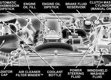
ENGINE DATA PLATE Use the information from the engine data plate when discussing service or sourcing parts for your engine. The engine data plate is located on the intake side of the breather cover.
WHAT TO DO IN EMERGENCIES
CONTENTS
m Hazard Warning Lights m Adding Fuel — 24–Valve Cummins Turbo
. . . . . . . . . . . . . . . . . . 296
Diesel . . . . . . . . . . . . . . . . . . . . . . . . . . . . . . . 297
m Jack Location . . . . . . . . . . . . . . . . . . . . . . . . . . 298
N All Models . . . . . . . . . . . . . . . . . . . . . . . . . . 298
m Changing A Flat Tire . . . . . . . . . . . . . . . . . . . . 299
N Removing The Spare Tire . . . . . . . . . . . . . . . . 299
N Tire Changing Procedure . . . . . . . . . . . . . . . . 300
m Hoisting . . . . . . . . . . . . . . . . . . . . . . . . . . . . . 309N With Portable Starting Unit
m Jump-Starting . . . . . . . . . . . . . . . . . . . . . . . . . 310
. . . . . . . . . . . . . . 313
m Freeing A Stuck Vehicle . . . . . . . . . . . . . . . . . . 313
m Emergency Tow Hooks — If Equipped . . . . . . . . 314
m Towing A Disabled Vehicle . . . . . . . . . . . . . . . . 315
N 4-Wheel- Drive Vehicles . . . . . . . . . . . . . . . . . 315
N 2–Wheel- Drive Vehicles . . . . . . . . . . . . . . . . 315296 WHAT TO DO IN EMERGENCIES
HAZARD WARNING LIGHTS The Hazard Warning switch is mounted on the top of the steering column as shown in the illustration.
To engage the Hazard Warning lights, depress the button on the top of the steering column. When the Hazard Warning switch is activated, all directional turn signals
will flash off and on to warn oncoming traffic of an emergency. Push the button a second time to turn off the flashers. This is an emergency warning system and should not be used when the vehicle is in motion. Use it when your vehicle is disabled and is creating a safety hazard for other motorists. When you must leave the vehicle to seek assistance, the Hazard Warning lights will continue to operate even though the ignition switch is OFF. NOTE: With extended use, the Hazard Warning lights may discharge your battery.
ADDING FUEL — 24–VALVE CUMMINS TURBO DIESEL
WARNING!
A fire may result if fuel is pumped into a portable container that is on a truck bed. You could be burned. Always place fuel containers on the ground while filling.
NOTE: When a diesel engine is allowed to run out of fuel, air is pulled into the fuel system. You may try priming as described below. However, if the engine will not start, refer to the fuel priming procedure in the Service Manual or have the vehicle towed to an authorized Dodge dealer.
WHAT TO DO IN EMERGENCIES 297
WARNING!
Do not open the high pressure fuel system with the engine running. Engine operation causes high fuel pressure. High pressure fuel spray can cause serious injury or death.
Priming if the engine has run out of fuel 1. Add a substantial quantity of fuel to the tank 5 to 10
gallons (19 to 38L). 2. Crank the engine for 1 to 2 seconds. If the engine does not start, then release the key or starter button back to the RUN position (do not turn the key back to the OFF position). The electric fuel transfer pump will continue to run and purge air from the system for about 25 seconds. After 25 seconds, attempt to start the engine again. 3. Start the engine using the Normal Starting Procedure.Remove the jack and tools by loosening the thumb screw and sliding the assembly from under the seat.
298 WHAT TO DO IN EMERGENCIES
4. Repeat the procedure if the engine does not start.
CAUTION!
Do not engage the starter motor for more than 15
seconds at a time. Allow two minutes between the cranking intervals.NOTE: The engine may run rough until the air is forced from all the fuel lines.
JACK LOCATION
All Models The jack and jack tools are stored under the passenger seat. Lift the flap on the side of the seat for access.
WARNING!
CHANGING A FLAT TIRE
WHAT TO DO IN EMERGENCIES 299
The jack is designed to use as a tool for changing tires only. The jack should not be used to lift the vehicle for service purposes, unless suitable sup- ports are placed under the vehicle as a safety mea- sure. The vehicle should be jacked on a firm level surface only. Avoid ice or slippery areas.
WARNING!
After using the jack and tools, always reinstall them in the original carrier and location. While driving you may experience, abrupt stopping, rapid accelera- tion, or sharp turns. A loose jack, tools, bracket or other objects in the vehicle may move around with force, resulting in serious injury.
Removing The Spare Tire Remove the spare tire before attempting to jack the truck. Attach the wheel wrench to the jack extension tube. Insert the tube through the access hole between the lower tailgate and the top of the bumper and into the winch mechanism tube. Rotate the wheel wrench handle coun- terclockwise until the spare tire is on the ground with enough cable slack to allow you to pull it out from under the vehicle. When the spare is clear, tilt the retainer at the end of the cable and pull it through the center of the wheel.
300 WHAT TO DO IN EMERGENCIES
It is recommended that you stow the flat or spare to avoid tangling the loose cable. NOTE: The winch mechanism is designed for use with the jack extension tube only. Use of an air wrench or other power tools is not recommended and can damage the winch.
Tire Changing Procedure
WARNING!
Getting under a jacked-up vehicle is dangerous. The vehicle could slip off the jack and fall on you. You could be crushed. Never get any part of your body under a vehicle that is on a jack. Never start or run the engine while the vehicle is on a jack. If you need to get under a raised vehicle, take it to a service center where it can be raised on a lift.
Do not raise this vehicle using a bumper jack. The jack is designed as a tool for changing tires on this vehicle only. It is not recommended that the jack be used for service purposes or to lift more than one wheel at a time.
Preparations Park the vehicle on a firm level surface, avoiding ice or slippery areas. Set the parking brake and place the gear selector in PARK (automatic transmission) or REVERSE (manual transmission). On four-wheel drive vehicles, shift the transfer case to the “4L” position.
WARNING!
Do not attempt to change a tire on the side of the vehicle close to moving traffic. Pull far enough off the road to avoid the danger of being hit when operating the jack or changing the wheel. † Turn on the Hazard Warning Flasher.
WHAT TO DO IN EMERGENCIES 301
† Block both the front and rear of the wheel diagonally oppo- site the jacking position. For example, front wheel is being changed, block the left rear wheel. † Passengers should not remain in the vehicle when the
the right
if
vehicle is being jacked.
302 WHAT TO DO IN EMERGENCIES
Instructions
WARNING!
be raised.
Carefully follow these tire changing warnings to help prevent personal injury or damage to your vehicle: † Always park on a firm, level surface as far from the edge of the roadway as possible before raising the vehicle. † Block the wheel diagonally opposite the wheel to † Apply the parking brake firmly before jacking. † Never start the engine with the vehicle on a jack. † Do not let anyone sit in the vehicle when it is on † Do not get under the vehicle when it is on a jack. † Only use the jack in the positions indicated. † If working on or near a roadway, be extremely
a jack.
careful of motor traffic.
1. Remove the spare wheel, jack, and tools from storage. 2. Using the wheel wrench, loosen, but do not remove, the wheel nuts by turning them counterclockwise one turn while the wheel is still on the ground. 3. For 2500/3500 4x2 series trucks, when changing a front wheel, place the bottle jack under the frame rail behind the wheel. Locate the jack as far forward as possible on the straight part of the frame. For 2500/3500 4x4 series trucks, when changing the front wheel, assemble the jack drive tube to the jack and connect the drive tube to the extension tube. Place the jack under the axle as close to the tire as possible with the drive tubes extending to the front. Connect the jack tube extension and wheel wrench.
When changing a rear wheel, assemble the jack drive tube to the jack and connect the drive tube to the extension tube. Place the jack under the axle between the spring and the shock absorber with the drive tubes extending to the rear. Connect the jack tube extension and wheel wrench. Before raising the wheel off the ground, make sure that the jack will not damage surrounding truck parts and adjust the jack position as required.
If the jack will not lower by turning the dial NOTE: (thumb wheel) by hand, it may be necessary to use the jack drive tube in order to lower the jack.
WHAT TO DO IN EMERGENCIES 303
2500/3500 4X2 Jacking Location
304 WHAT TO DO IN EMERGENCIES
4. By rotating the wheel wrench clockwise, raise the vehicle until the wheel just clears the surface.
WARNING!
Raising the vehicle higher than necessary can make the vehicle unstable and cause an accident. It could slip off the jack and hurt someone near it. Raise the vehicle only enough to remove the tire.
5. Remove the wheel nuts and pull the wheel off. Install the spare wheel and wheel nuts with the cone shaped end of the nuts toward the wheel on 2500/3500 single rear wheel (SRW) models. On 3500 dual rear wheel models (DRW) the lug nuts are a two piece assembly with a flat face. Lightly tighten the nuts. To avoid risk of forcing the vehicle off the jack, do not fully tighten the nuts until the vehicle has been lowered. 6. Using the wheel wrench, finish tightening the nuts using a crisscross pattern. Correct nut tightness is 135 ft. lbs. (183 N·m) torque for 2500/3500 single rear wheel
WHAT TO DO IN EMERGENCIES 305
(SRW) models and 145 ft. lbs. (197 N·m) for 3500 dual rear wheel models. If in doubt about the correct tightness, have them checked with a torque wrench by your dealer or at a service station.
WARNING!
A loose tire or jack thrown forward in a collision or hard stop could injure someone in the vehicle. Always stow the jack parts and the extra tire and wheel in the places provided.
7. Install wheel center cap and remove wheel blocks. Do not install chrome or aluminum wheel center caps on the spare wheel. This may result in cap damage. 8. Lower the jack to its fully closed position. If the jack will not lower by turning the dial (thumb wheel) by
306 WHAT TO DO IN EMERGENCIES
hand, it may be necessary to use the jack drive tube in order to lower the jack. Stow the replaced tire, jack, and tools as previously described. 9. Adjust the tire pressure when possible. NOTE: Do not oil wheel studs. For chrome wheels, do not substitute with chrome plated wheel nuts. Hub Caps The hub caps must be removed before raising the vehicle off the ground. For 2500/3500 single rear wheel (SRW) models, use the blade on the end of the lug wrench to pry the cap off. On 3500 models with dual rear wheels (DRW), you must first remove the hub caps. The jack handle driver has a hook at one end that will fit in the pry off notch of the rear hub caps. Position the hook and pull out on the ratchet firmly. The cap should pop off. The wheel skins can now be removed. For the front hub cap on 3500
models use the blade on the end of the lug wrench to pry the caps off. The wheel skin can now be removed. You must use the flat end of the lug wrench to pry off the wheel skins. Insert the flat tip completely and using a back and forth motion, loosen the wheel skin. Repeat this procedure around the tire until the skin pops off. Replace the wheel skins first using a rubber mallet. When replacing the hub caps, tilt the cap retainer over the lugnut bolt circle and strike the high side down with a rubber mallet. Be sure that the hub caps and wheel skins are firmly seated around the wheel. 8-Stud — Dual Rear Wheels Dual wheels are flat mounted, center piloted. The lug nuts are a two piece assembly. When the tires are being rotated or replaced, clean these lug nuts and add 2 drops of oil at the interface between the hex and the washer.
WHAT TO DO IN EMERGENCIES 307
Dual wheel models require a special heavy-duty lug nut tightening adapter (included with the vehicle) to cor- rectly tighten the lug nuts. Also, when it is necessary to remove and install dual rear wheels, use a proper vehicle lifting device. NOTE: When installing a spare tire as part of a dual rear wheel end combination, the tire diameter of the two individual tires must be compared. If there is a significant difference, the larger tire should be installed in a front location. Correct direction of rotation for dual tire instal- lations must also be observed. These dual rear wheels should be tightened as follows:
Slots in the wheels will assist in properly orienting the inner and outer wheels. Align these slots when assem- bling the wheels for best access to the tire valve on the inner wheel. The tires of both dual wheels must be completely off the ground when tightening to insure wheel centering and maximum wheel clamping.
308 WHAT TO DO IN EMERGENCIES
1. Tighten the wheel nuts in the numbered sequence to a snug fit. 2. Retighten the wheel nuts in the same sequence to the torques listed in the table. Go through the sequence a second time to verify that specific torque has been achieved. Retighten to specifications at 100 miles (160
km) and after 500 miles (800 km). It is recommended that wheel stud nuts be kept torqued to specifications at all times. Torque wheel stud nuts to specifications at each lubrication interval. Wheel Nuts All wheel nuts should be tightened occasionally to elimi- nate the possibility of wheel studs being sheared or the bolt holes in the wheels becoming elongated. This is especially important during the first few hundred miles of operation to allow the wheel nuts to become properly set. All nuts should first be firmly seated against thewheel. The nuts should then be tightened to recom- mended torque. Tighten the nuts to final torque in increments. Progress around the bolt circle, tightening the nut opposite to the nut just previously tightened until final torque is achieved. Recommended torques are shown in the following chart. Disc Wheels
Type Nut Stud Size Torque Ft. Lbs.
Cone Flanged
9/16-18
9/16-18120-150
130-160To Stow The Flat Or Spare Turn the wheel so that the valve stem is down. Slide the wheel retainer through the center of the wheel and position it properly across the wheel opening. For convenience in checking the spare tire inflation, stow with the valve stem toward the rear of the vehicle.
Torque Newton Meters 160-200
190-220WHAT TO DO IN EMERGENCIES 309
Attach the wheel wrench to the extension tube. Rotate the winch mechanism until the wheel is drawn into place against the underside of the vehicle. Continue to rotate until you feel the winch mechanism slip or click 3 or 4
times. It cannot be overtightened. Push against the tire several times to be sure it is firmly in place.HOISTING A conventional floor jack may be used at the jacking locations, refer to the graphics that show jacking loca- tions. However, a floor jack or frame hoist must never be used on any other parts or the underbody.
CAUTION!
Never use a floor jack directly under the differential housing of a loaded truck or damage to your vehicle may result.
310 WHAT TO DO IN EMERGENCIES
JUMP-STARTING
WARNING!
To prevent personal injury or damage to clothing, do not allow battery fluid to contact eyes, skin or fabrics. Do not lean over a battery when connecting jumper cables or allow cable clamps to touch each other. Keep open flames or sparks away from battery vent holes. Always wear eye protection when work- ing with batteries. Do not use a booster battery or any other booster source that has a greater than 12 volt system, i.e. do not use a 24 volt power source.
NOTE: Replacement batteries should both be of equal size to prevent damage to the vehicles charging system. Your vehicle is equipped with two 12–volt batteries. If it becomes necessary to use a booster battery, with jumper cables, to start a vehicle’s engine because its batteries are discharged, the following procedure should be followed: Set the parking brake and place an automatic transmis- sion in PARK (or NEUTRAL for a manual transmission). Turn off lights, heater and other electrical loads. Observe charge indicator (if equipped) in both batteries. If indica- tor (if equipped) is light or yellow on either battery, replace that battery.
CAUTION!
Use the Jump Start Procedure only when the charge indicator (if equipped) in both batteries is dark in the center. Do not attempt jump starting when either battery charge indicator (if equipped) is bright or yellow. If charge indicator (if equipped) has a green dot in the center, failure to start is not due to a discharged battery and cranking system should be checked.
1. Attach one jumper cable to the positive terminal of booster battery and the other end of the same cable to the positive terminal of the discharged battery.
WHAT TO DO IN EMERGENCIES 311
WARNING!
Do not permit vehicles to touch each other as this could establish a ground connection and personal injury could result.
312 WHAT TO DO IN EMERGENCIES
2. Connect one end of the other jumper cable to negative (-) post of booster battery. Connect the other end of the jumper cable to a good ground on the engine block of the vehicle with the discharged battery. Make sure a good connection is made, free of dirt and grease.
WARNING!
† Do not connect the cable to the negative post of the discharge battery. The resulting electrical spark could cause the battery to explode. † During cold weather when temperatures are be- low freezing point, electrolyte in a discharged battery may freeze. Do not attempt jump starting because the battery could rupture or explode. The battery temperature must be brought up above freezing point before attempting jump start.
3. Take care that the clamps from one cable do not inadvertently touch clamps from the other cable. Do not lean over the battery when making connection. The negative connection must provide good electrical con- ductivity and current carrying capacity. 4. After the engine is started or if the engine fails to start, cables must be disconnected in the following order:
a. Disconnect the negative cable at the engine ground. b. Disconnect the negative cable at the negative post on booster battery. c. Disconnect the cable from the positive post of both batteries.
WARNING!
CAUTION!
WHAT TO DO IN EMERGENCIES 313
Any procedure other than above could result in: 1. Personal injury caused by electrolyte squirting out the battery vent; 2. Personal injury or property damage due to battery explosion; 3. Damage to charging system of booster vehicle or of immobilized vehicle.
With Portable Starting Unit There are many types of these units available. Follow the manufacturer’s instructions for necessary precautions and operation.
It is very important that the starting unit operating voltage does not exceed 12 Volts D.C. or damage to battery, starter motor, alternator, or electrical system may occur.
FREEING A STUCK VEHICLE If vehicle becomes stuck in snow, sand, or mud, it can often be moved by a rocking motion. Move the gear selector rhythmically between DRIVE and REVERSE, while applying slight pressure to the accelerator. In general, the least amount of accelerator pedal pressure to maintain the rocking motion without spinning the wheels or racing the engine is most effective. Racing the engine or spinning the wheels, due to the frustration of not freeing the vehicle, may lead to transmission over- heating and failure. Allow the engine to idle with the
314 WHAT TO DO IN EMERGENCIES
transmission selector in NEUTRAL for at least one minute after every five rocking-motion cycles. This will minimize overheating and reduce the risk of transmis- sion failure during prolonged efforts to free a stuck vehicle.
EMERGENCY TOW HOOKS — IF EQUIPPED Your vehicle may be equipped with emergency tow hooks.
WARNING!
Chains are not recommended for freeing a stuck vehicle. Chains may break, causing serious injury or death.
WARNING!
Stand clear of vehicles when pulling with tow hooks. Tow straps and chains may break, causing serious injury.
CAUTION!
Tow hooks are for emergency use only, to rescue a vehicle stranded off road. Do not use tow hooks for tow truck hookup or highway towing. You could damage your vehicle.
TOWING A DISABLED VEHICLE Proper towing or lifting equipment is required to prevent damage to your vehicle. Use only tow bars and other equipment designed for the purpose, following equip- ment manufacturer’s instructions. Use of safety chains is mandatory. Attach a tow bar or other towing device to the main structural members of the vehicle—not to bumpers or associated brackets. State and local laws applying to vehicles under tow must be observed. 4-Wheel- Drive Vehicles
CAUTION!
To avoid damage to the transfer case while towing, always use one of the following methods.
WHAT TO DO IN EMERGENCIES 315
The manufacturer recommends towing with all wheels off the ground. Acceptable methods are to tow vehicle on a flatbed or with one end of vehicle raised and the opposite end on a towing dolly. 2–Wheel- Drive Vehicles Provided that the transmission is operable, tow with the transmission in Neutral and the ignition key in the OFF position along with the front wheels raised and the rear wheels on the ground. Speed must not exceed 30 mph (50
km/h) and distance must not exceed 15 miles (25 km). If the vehicle is to be towed more than 15 miles (25 km) the vehicle must be towed with the rear wheels raised and the front wheels on the ground. It may also be towed on a flatbed or with the front wheels raised and the rear wheels on a dolly.MAINTAINING YOUR VEHICLE
CONTENTS
m Engine Compartment . . . . . . . . . . . . . . . . . . . . 320
N 5.9L/5.9L HO Cummins Turbo Diesel . . . . . . . 320
m Onboard Diagnostic System (OBD II) . . . . . . . . . 321
m Replacement Parts . . . . . . . . . . . . . . . . . . . . . . 322
m Dealer Service . . . . . . . . . . . . . . . . . . . . . . . . . 322
m Service Information . . . . . . . . . . . . . . . . . . . . . 322
m Maintenance Procedures . . . . . . . . . . . . . . . . . . 325
N Engine Oil . . . . . . . . . . . . . . . . . . . . . . . . . . 325
N Drive Belt . . . . . . . . . . . . . . . . . . . . . . . . . . . 331N Engine Air Cleaner Filter . . . . . . . . . . . . . . . . 331
N Draining Fuel/Water Separator Filter . . . . . . . 334
N Maintenance Free Batteries . . . . . . . . . . . . . . . 336
N Air Conditioner Maintenance . . . . . . . . . . . . . 338
N Power Steering — Fluid Check . . . . . . . . . . . . 339
N Front Suspension Ball Joints . . . . . . . . . . . . . . 340
N Steering Linkage — Inspection . . . . . . . . . . . . 340
N Front Axle Universal Drive Joints And PivotBearings . . . . . . . . . . . . . . . . . . . . . . . . . . . . 340
318 MAINTAINING YOUR VEHICLE
N Body Lubrication . . . . . . . . . . . . . . . . . . . . . 340
N Windshield Wiper Blades . . . . . . . . . . . . . . . . 341
N Windshield Washers . . . . . . . . . . . . . . . . . . . 341
N Exhaust System . . . . . . . . . . . . . . . . . . . . . . 342
N Cooling System . . . . . . . . . . . . . . . . . . . . . . . 343
N Fan . . . . . . . . . . . . . . . . . . . . . . . . . . . . . . . 347
N Charge Air Cooler (Inter-Cooler) . . . . . . . . . . 347
N Hoses And Vacuum/Vapor Harnesses . . . . . . . 348
N Brake System . . . . . . . . . . . . . . . . . . . . . . . . 348
N Clutch Linkage . . . . . . . . . . . . . . . . . . . . . . . 350
N Clutch Hydraulic System . . . . . . . . . . . . . . . . 351
N Propeller Shaft Universal Joints . . . . . . . . . . . 351N Rear Axle And 4X4 Front Driving Axle Fluid
Level . . . . . . . . . . . . . . . . . . . . . . . . . . . . . . 351
N Transfer Case — If Equipped . . . . . . . . . . . . . 352
N Manual Transmission — If Equipped . . . . . . . 352
N Automatic Transmission . . . . . . . . . . . . . . . . 353
N Front Wheel Bearings . . . . . . . . . . . . . . . . . . 355
N Selection Of Lubricating Grease . . . . . . . . . . . 356
N Noise Control System RequiredMaintenance & Warranty . . . . . . . . . . . . . . . . 357
N Appearance Care And Protection From
Corrosion . . . . . . . . . . . . . . . . . . . . . . . . . . . 362
m Fuse And Relay Center . . . . . . . . . . . . . . . . . . . 366
m Vehicle Storage . . . . . . . . . . . . . . . . . . . . . . . . 366m Replacement Light Bulbs m Bulb Replacement
. . . . . . . . . . . . . . . . . 367
. . . . . . . . . . . . . . . . . . . . . . 367N Headlight (Halogen)/Front Park And Turn
Lights . . . . . . . . . . . . . . . . . . . . . . . . . . . . . 367
N Tail, Stop, Turn And Backup Lights . . . . . . . . . 371
N Center High-Mounted Stoplight With CargoLight . . . . . . . . . . . . . . . . . . . . . . . . . . . . . . 373
N Cab Top Clearance Lights — If Equipped . . . . 375
N Tailgate ID Lights (Dual Rear Wheels) . . . . . . . 376MAINTAINING YOUR VEHICLE 319
N Side Marker Lights (Dual Rear Wheels) . . . . . . 378
N Fog Lights . . . . . . . . . . . . . . . . . . . . . . . . . . 378
m Fluid Capacities . . . . . . . . . . . . . . . . . . . . . . . . 379
m Recommended Fluids, Lubricants And GenuineParts . . . . . . . . . . . . . . . . . . . . . . . . . . . . . . . . 380
N Engine . . . . . . . . . . . . . . . . . . . . . . . . . . . . . 380
N Chassis . . . . . . . . . . . . . . . . . . . . . . . . . . . . 381320 MAINTAINING YOUR VEHICLE
ENGINE COMPARTMENT
5.9L/5.9L HO CUMMINS TURBO DIESEL
ONBOARD DIAGNOSTIC SYSTEM (OBD II) CARB emission control vehicles are equipped with a sophisticated onboard diagnostic system called OBDII. This system monitors the performance of the emissions, engine, and automatic transmission control systems. When these systems are operating properly, your vehicle will provide excellent performance and fuel economy, as well as engine emissions well within current government regulations. If any of these systems require service, the OBD II system will turn on the “Malfunction Indicator Light.” It will also store diagnostic codes and other information to assist your service technician in making repairs. Al- though your vehicle will usually be driveable and not need towing, see your dealer for service as soon as possible.
MAINTAINING YOUR VEHICLE 321
CAUTION!
Prolonged driving with the “Malfunction Indicator Light” on could cause further damage to the emis- sion control system. It could also affect fuel economy and driveability. The vehicle must be serviced before any emissions tests can be performed. If the “Malfunction Indicator Light” is flashing, severe catalytic converter damage and power loss will soon occur. Immediate service is required.
322 MAINTAINING YOUR VEHICLE
REPLACEMENT PARTS Use of genuine Mopart parts for normal/scheduled maintenance and repairs is highly recommended to in- sure the designed performance. Damage or failures caused by the use of non-Mopar parts for maintenance and repairs will not be covered by the manufacturer’s warranty.
DEALER SERVICE Your dealer has the qualified service personnel, special tools and equipment to perform all service operations in an expert manner. Service manuals are available which include detailed service information for your vehicle. Refer to these manuals before attempting any procedure yourself. NOTE: systems can result against you.
Intentional tampering with emissions control in civil penalties being assessed
WARNING!
You can be badly injured working on or around a motor vehicle. Do only that service work for which you have the knowledge and the proper equipment. If you have any doubt about your ability to perform a service job, take your vehicle to a competent mechanic.
SERVICE INFORMATION Mopar Fluids, Lubricants and Parts are available from your dealer and will help you keep your vehicle operat- ing at its best. Your dealer also has the qualified service personnel, special tools and equipment to perform all service operations in an expert manner. Service manuals are available which include detailed service information for your vehicle. Refer to these manuals before attempt- ing any procedure yourself. See Service Publications information at the back of this manual.
NOTE: Failure to perform maintenance service at the specified intervals as outlined in the Maintenance Schedules may void provisions of your Vehicle Warranty.
CAUTION!
To maintain your vehicle safely follow these guide- lines: † Watch your vehicle’s mileage and check your Mainte- nance Schedules regularly for required servicing. Ex- cessive wear or damage to certain vehicle components can result if required services are not performed.
† If you have your vehicle undercoated,
inspect for undercoating material on the propeller shafts. Such material could cause the shafts to become unbalanced and result in drivetrain vibrations. Remove any under- coating with solvent.
MAINTAINING YOUR VEHICLE 323
† If you have your vehicle undercoated, make sure no undercoating material is sprayed on the exhaust sys- tem or components of the seat belt system.
It is not possible for the manufacturer and NOTE: Cummins, Inc. to anticipate every possible circumstance that can involve a potential hazard.
WARNING!
To maintain your vehicle safely and avoid personal injury, follow these guidelines: † Never spray or pour diesel fuel, flammable liquid or starting fluids (ether) into the air cleaner canister, air intake piping or turbocharger inlet in an attempt to start the vehicle.
324 MAINTAINING YOUR VEHICLE
† Do not use alcohol or gasoline as a fuel blending agent. They can be unstable under certain conditions and be hazardous or explosive when mixed with diesel fuel. † If an engine has been operating and the coolant is hot, allow the engine to cool before you slowly loosen the filler cap and relieve the pressure from the cooling