- Download PDF Manual
-
Extended use of this mode is not recommended. • The use of the Recirculation mode in cold or damp weather will cause windows to fog on the inside, because of moisture buildup inside the vehicle. Select the outside air position for maximum defogging. • The A/C will engage automatically to prevent fogging when the recirculation button is pressed and the mode control is set to panel or panel / floor. • The A/C can be deselected manually without disturb- • When the ignition switch is turned to the LOCK position, the recirculation feature will be cancelled.
ing the mode control selection.
UNDERSTANDING YOUR INSTRUMENT PANEL 277
Air Conditioning Control
Press this button to engage the Air Conditioning. A light will illuminate when the Air Conditioning system is engaged. Rotating the dial left into the blue area of the scale indicates cooler temperatures, while rotating right into the red area indicates warmer tem- peratures.
NOTE: The air conditioning compressor will not engage until the engine has been running for about 10 seconds. • MAX A/C For maximum cooling use the A/C and recirculation buttons at the same time. • ECONOMY MODE If economy mode is desired, press the A/C button to turn OFF the indicator light and the A/C compressor. Then, move the temperature control to the desired temperature.
278 UNDERSTANDING YOUR INSTRUMENT PANEL Automatic Temperature Control (ATC) — If Equipped
Automatic Temperature Control
Automatic Operation The Automatic Temperature Control system automati- cally maintains the climate in the cabin of the vehicle at the comfort levels desired by the driver and passenger.
Operation of the system is quite simple. 1. Turn the Mode Control knob (on the right) and the Blower Control knob (on the left) to AUTO. NOTE: The AUTO position performs best for front seat occupants only.
2. Dial in the temperature you would like the system to maintain by rotating the Temperature Control knob. Once the comfort level is selected, the sys- tem will maintain that level automati- cally using the heating system. Should the desired comfort level require air conditioning, the system will automatically make the adjustment. You will experience the greatest efficiency by simply allowing the system to function automatically. Selecting the “O” (OFF) position on the blower control stops the system completely and closes the outside air intake.
without affecting automatic operation.
The recommended setting for maximum comfort is 72°F (22°C) for the average person; however, this may vary. NOTE: • The temperature setting can be adjusted at anytime • Pressing the Air Conditioning Control button while in AUTO mode will cause the LED in the control button to flash three times and then turn off. This indicates that the system is in AUTO mode and requesting the air conditioning is not necessary. • If your air conditioning performance seems lower than expected, check the front of the A/C condenser located in front of the radiator for an accumulation of dirt or insects. Clean with a gentle water spray from behind the radiator and through the condenser. Fabric front fascia protectors may reduce airflow to the condenser, reducing air conditioning performance.
UNDERSTANDING YOUR INSTRUMENT PANEL 279
Blower Control
For full automatic operation or for automatic blower operation, turn the knob to the AUTO position. In manual mode there are six blower speeds that can be individual selected. In off posi- tion the blower will shut off.
Manual Operation This system offers a full complement of manual override features, which consist of Blower Preferred Automatic, Mode Preferred Automatic, or Blower and Mode Pre- ferred Automatic. This means the operator can override the blower, the mode, or both. There is a manual blower range for times when the AUTO setting is not desired. The blower can be set to any fixed blower speed by rotating the Blower Control knob (on the left). NOTE: Please read the Automatic Temperature Control Operation Chart that follows for details.
280 UNDERSTANDING YOUR INSTRUMENT PANEL
The operator can override the AUTO mode setting to change airflow distribution by rotating the Mode Control knob (on the right) to one of the following positions. • Panel
Air is directed through the outlets in the instrument panel. These outlets can be adjusted to direct airflow. NOTE: The center instrument panel outlets can be aimed so that they are directed toward the rear seat passengers for maximum airflow to the rear. • Bi-Level
Air is directed through the panel and floor outlets.
NOTE: For all settings, except full cold or full hot, there is a difference in temperature between the upper and lower outlets. The warmer air flows to the floor outlets. This feature gives improved comfort during sunny but cool conditions.
UNDERSTANDING YOUR INSTRUMENT PANEL 281
• Floor
Air is directed through the floor outlets with a small amount flowing through the defrost and side
window demist outlets. • Mix
Air is directed through the floor, defrost, and side window demist outlets. This setting works best in cold or snowy conditions that require extra heat to the windshield. This setting is good for maintaining comfort while reducing moisture on the windshield. • Defrost
Air is directed through the windshield and side window demist outlets. Use this mode with maxi- mum blower and temperature settings for best wind- shield and side window defrosting.
282 UNDERSTANDING YOUR INSTRUMENT PANEL
• Air Conditioner Control
Press this button to turn on the air conditioning during manual operation only. When the air conditioning is turned on, cool dehumidified air will flow through the outlets selected with the Mode control dial. Press this but- ton a second time to turn OFF the air conditioning. An LED in the button illuminates when manual compressor operation is selected. • Recirculation Control
The system will automatically control recircu- lation. However, pressing the Recirculation Control button will temporarily put the system in recirculation mode (ten minutes). This can be used when outside conditions such as smoke, odors, dust, or high humidity are present. Activating recircula- tion will cause the LED in the control button to illumi- nate. After ten minutes, the system will return to normal AUTO mode function and the LED will turn off.
NOTE: • When the ignition switch is turned to the LOCK position, the recirculation feature will be cancelled. • In cold weather, use of the Recirculation mode may lead to excessive window fogging. The Recirculation mode is not allowed in the floor, defrost, or defrost/ floor mode in order to improve window clearing. Recirculation will be disabled automatically if these modes are selected. • Extended use of recirculation may cause the windows to fog. If the interior of the windows begins to fog, press the Recirculation button to return to outside air. Some temp/humidity conditions will cause captured interior air to condense on windows and hamper visibility. For this reason, the system will not allow Recirculation to be selected while in floor, defrost, or defrost/floor mode. Attempting to use the recircula- tion while in these modes will cause the LED in the control button to blink and then turn off.
• Most of the time, when in Automatic Operation, you can temporarily put the system into Recirculation Mode by pressing the Recirculation button. However, under certain conditions, while in Automatic Mode, the system is blowing air out the defrost vents. When these conditions are present, and the Recirculation button is pressed, the indicator will flash and then turn off. This tells you that you are unable to go into Recirculation Mode at this time. If you would like the system to go into Recirculation Mode, you must first move the Mode knob to Panel, Panel/Floor and then press the Recirculation button. This feature reduces the possibility of window fogging.
Operating Tips
NOTE: Refer to the chart at the end of this section for suggested control settings for various weather condi- tions.
UNDERSTANDING YOUR INSTRUMENT PANEL 283
Summer Operation The engine cooling system in air-conditioned vehicles must be protected with a high-quality antifreeze coolant to provide proper corrosion protection and to protect against engine overheating. A solution of 50% ethylene glycol antifreeze coolant and 50% water is recommended. Refer to “Maintenance Procedures” in “Maintaining Your Vehicle” for proper coolant selection. Winter Operation Use of the air Recirculation Mode during winter months is not recommended because it may cause window fogging. Vacation Storage Anytime you store your vehicle, or keep it out of service (i.e., vacation) for two weeks or more, run the air conditioning system at idle for about five minutes in the fresh air and high blower settings. This will ensure adequate system lubrication to minimize the possibility of compressor damage when the system is started again.
284 UNDERSTANDING YOUR INSTRUMENT PANEL Window Fogging Interior fogging on the windshield can be quickly re- moved by turning the mode selector to Defrost. The Defrost/Floor mode can be used to maintain a clear windshield and provide sufficient heating. If side win- dow fogging becomes a problem, increase blower speed. Vehicle windows tend to fog on the inside in mild but rainy or humid weather. NOTE: Recirculate without A/C should not be used for long periods as fogging may occur. Side Window Demisters A side window demister outlet is located at each end of the instrument panel. These non-adjustable outlets direct air toward the side windows when the system is in the FLOOR, MIX, or DEFROST mode. The air is directed at the area of the windows through which you view the outside mirrors.
Outside Air Intake Make sure the air intake, located directly in front of the windshield, is free of obstructions such as leaves. Leaves collected in the air intake may reduce airflow, and if they enter the plenum, they could plug the water drains. In winter months, make sure the air intake is clear of ice, slush, and snow. A/C Air Filter — If Equipped The A/C Filter prevents most dust and pollen from entering the cabin. The filter acts on air coming from outside the vehicle and recirculated air within the pas- senger compartment. Refer to “Maintenance Procedures” in “Maintaining Your Vehicle” for A/C Air Filter service information or see your authorized dealer for service. Refer to “Maintenance Schedules” for filter service intervals.
Control Setting Suggestions for Various Weather Conditions
UNDERSTANDING YOUR INSTRUMENT PANEL 285
STARTING AND OPERATING
CONTENTS
䡵 Starting Procedures . . . . . . . . . . . . . . . . . . . . 291
▫ Normal Starting . . . . . . . . . . . . . . . . . . . . . 291
▫ Extreme Cold Weather(Below –20°F Or –29°C) . . . . . . . . . . . . . . . . 291
▫ If Engine Fails To Start . . . . . . . . . . . . . . . . 292
▫ After Starting . . . . . . . . . . . . . . . . . . . . . . . 293
䡵 Engine Block Heater — If Equipped . . . . . . . . 293
䡵 Automatic Transmission . . . . . . . . . . . . . . . . . 294
▫ Key Ignition Park Interlock . . . . . . . . . . . . . 295▫ Brake/Transmission Interlock System . . . . . . 295
▫ Four–Speed Automatic Transmission –3.7L Engine . . . . . . . . . . . . . . . . . . . . . . . . 295
▫ Gear Ranges . . . . . . . . . . . . . . . . . . . . . . . . 296
▫ Five–Speed Automatic Transmission –4.0L Engine . . . . . . . . . . . . . . . . . . . . . . . . 300
▫ Gear Ranges . . . . . . . . . . . . . . . . . . . . . . . . 300
䡵 Four-Wheel Drive Operation — If Equipped . . 304
▫ Single-Speed Part-Time Transfer Case . . . . . . 304288 STARTING AND OPERATING
▫ Shifting Procedure – Electronically Shifted
Transfer Case . . . . . . . . . . . . . . . . . . . . . . . 306
䡵 On-Road Driving Tips . . . . . . . . . . . . . . . . . . 307
䡵 Power Steering . . . . . . . . . . . . . . . . . . . . . . . 307
▫ Power Steering Fluid Check . . . . . . . . . . . . . 308
䡵 Parking Brake . . . . . . . . . . . . . . . . . . . . . . . . 309
䡵 Anti-Lock Brake System . . . . . . . . . . . . . . . . . 311
䡵 Electronic Brake Control System . . . . . . . . . . . 313
▫ Anti-Lock Brake System (ABS) . . . . . . . . . . . 314
▫ Traction Control System (TCS) . . . . . . . . . . . 314
▫ Brake Assist System (BAS) . . . . . . . . . . . . . . 315
▫ Electronic Roll Mitigation (ERM) . . . . . . . . . 316
▫ Electronic Stability Control (ESC) . . . . . . . . . 316▫ ESC Activation/Malfunction Indicator Light
And ESC Off Indicator Light
. . . . . . . . . . . . 319
䡵 Tire Safety Information . . . . . . . . . . . . . . . . . 320
▫ Tire Markings . . . . . . . . . . . . . . . . . . . . . . . 320
▫ Tire Identification Number (TIN) . . . . . . . . . 323
▫ Tire Terminology And Definitions . . . . . . . . . 324
▫ Tire Loading And Tire Pressure . . . . . . . . . . 325
䡵 Tires — General Information . . . . . . . . . . . . . 329
▫ Tire Pressure . . . . . . . . . . . . . . . . . . . . . . . 329
▫ Tire Inflation Pressures . . . . . . . . . . . . . . . . 330
▫ Tire Pressures For High Speed Operation . . . 332
▫ Radial Ply Tires . . . . . . . . . . . . . . . . . . . . . 332
▫ Spare Tire Matching Original Equipped TireAnd Wheel – If Equipped . . . . . . . . . . . . . . 332
▫ Compact Spare Tire – If Equipped . . . . . . . . 333
▫ Full Size Spare – If Equipped . . . . . . . . . . . . 334
▫ Limited-Use Spare – If Equipped . . . . . . . . . 334
▫ Tire Spinning . . . . . . . . . . . . . . . . . . . . . . . 335
▫ Tread Wear Indicators . . . . . . . . . . . . . . . . . 336
▫ Life Of Tire . . . . . . . . . . . . . . . . . . . . . . . . 336
▫ Replacement Tires . . . . . . . . . . . . . . . . . . . . 337
䡵 Tire Chains . . . . . . . . . . . . . . . . . . . . . . . . . . 338
䡵 Tire Rotation Recommendations . . . . . . . . . . . 340
䡵 Tire Pressure Monitor System (TPMS) . . . . . . . 341
▫ Base System . . . . . . . . . . . . . . . . . . . . . . . . 343
▫ Premium System – If Equipped . . . . . . . . . . 346
▫ General Information . . . . . . . . . . . . . . . . . . 351STARTING AND OPERATING 289
䡵 Fuel Requirements . . . . . . . . . . . . . . . . . . . . . 351
▫ 3.7L Engine . . . . . . . . . . . . . . . . . . . . . . . . 351
▫ 4.0L Engine . . . . . . . . . . . . . . . . . . . . . . . . 351
▫ Reformulated Gasoline . . . . . . . . . . . . . . . . 352
▫ Gasoline/Oxygenate Blends . . . . . . . . . . . . . 352
▫ E-85 Usage In Non-Flex Fuel Vehicles . . . . . . 353
▫ MMT In Gasoline . . . . . . . . . . . . . . . . . . . . 354
▫ Materials Added To Fuel . . . . . . . . . . . . . . . 354
▫ Fuel System Cautions . . . . . . . . . . . . . . . . . 354
▫ Carbon Monoxide Warnings . . . . . . . . . . . . 355
. . . . . . . . . . . . . . . . . . . . . . . . . 356
▫ Fuel Filler Cap (Gas Cap) . . . . . . . . . . . . . . 356
▫ Loose Fuel Filler Cap Message . . . . . . . . . . . 358䡵 Adding Fuel
290 STARTING AND OPERATING 䡵 Vehicle Loading
▫ Certification Label
. . . . . . . . . . . . . . . . . . . . . . 358
. . . . . . . . . . . . . . . . . . . 358
䡵 Trailer Towing . . . . . . . . . . . . . . . . . . . . . . . . 361
▫ Common Towing Definitions . . . . . . . . . . . . 361
▫ Trailer Hitch Classification . . . . . . . . . . . . . . 366
▫ Trailer Towing Weights(Maximum Trailer Weight Ratings) . . . . . . . . 367
▫ Trailer And Tongue Weight . . . . . . . . . . . . . 369
▫ Towing Requirements . . . . . . . . . . . . . . . . . 370▫ Towing Tips . . . . . . . . . . . . . . . . . . . . . . . . 375
䡵 Recreational Towing
(Behind Motorhome, Etc.) . . . . . . . . . . . . . . . . 377
▫ Towing This VehicleBehind Another Vehicle . . . . . . . . . . . . . . . . 377
▫ Recreational Towing — Two-Wheel Drive
Models
. . . . . . . . . . . . . . . . . . . . . . . . . . . 377
▫ Recreational Towing — Four-Wheel Drive
Models
. . . . . . . . . . . . . . . . . . . . . . . . . . . 378
STARTING PROCEDURES Before starting your vehicle, adjust your seat, adjust both inside and outside mirrors, and fasten your seat belts.
WARNING!
Never leave children alone in a vehicle. Leaving children in a vehicle unattended is dangerous for a number of reasons. A child or others could be seri- ously or fatally injured. Do not leave the keys in the ignition. A child could operate power windows, other controls, or move the vehicle.
Start the engine with the shift lever in the NEUTRAL or PARK position. Apply the brake before shifting to any driving range. Normal Starting NOTE: Normal starting of either a cold or a warm engine is obtained without pumping or pressing the accelerator pedal.
STARTING AND OPERATING 291
Turn the ignition switch to the START position and release when the engine starts. If the engine fails to start within 10 seconds, turn the ignition switch to the LOCK position, wait 10 to 15 seconds, then repeat the “Normal Starting” procedure. Tip Start Feature Turn the ignition switch to START position and release it as soon as the starter engages. The starter motor will continue to run, but will automatically disengage itself when the engine is running. If the engine fails to start, the starter will disengage automatically in 10 seconds. If this occurs, turn the ignition switch to the LOCK position, wait 10 to 15 seconds, then repeat the “Normal Starting” procedure. Extreme Cold Weather (below –20°F or –29°C) To ensure reliable starting at these temperatures, the use of an externally powered electric engine block heater (available from your authorized dealer) is recommended.292 STARTING AND OPERATING If Engine Fails To Start
WARNING!
• Never pour fuel or other flammable liquids into the throttle body air inlet opening in an attempt to start the vehicle. This could result in a flash fire causing serious personal injury. • Do not attempt to push or tow your vehicle to get it started. Vehicles equipped with an automatic trans- mission cannot be started this way. Unburned fuel could enter the catalytic converter and once the engine has started, ignite and damage the converter and vehicle. If the vehicle has a discharged battery, booster cables may be used to obtain a start from a booster battery or the battery in another vehicle. This type of start can be dangerous if done improp- erly. Refer to “Jump Starting” in “What To Do In Emergencies” for further information.
CAUTION!
To prevent damage to the starter, do not crank the engine for more than 15 seconds at a time. Wait 10 to 15 seconds before trying again.
If the engine has been flooded, it may start to run, but not have enough power to continue running when the key is released. If this occurs, continue cranking with the accel- erator pedal pressed all the way to the floor. Release the accelerator pedal and the key once the engine is running smoothly. If the engine shows no sign of starting after two 15 sec- ond periods of cranking with the accelerator pedal held to the floor, repeat the “Normal Starting” or “Extreme Cold Weather” procedures.
With Tip Start If the engine fails to start after you have followed the “Normal Starting” or “Extreme Cold Weather” proce- dures, it may be flooded. To clear any excess fuel, press the accelerator pedal all the way to the floor and hold it. Then, turn the ignition switch to the START position and release it as soon as the starter engages. The starter motor will disengage automatically in 10 seconds. Once this occurs, release the accelerator pedal, turn the ignition switch to the LOCK position, wait 10 to 15 seconds, then repeat the “Normal Starting” procedure.
CAUTION!
To prevent damage to the starter, wait 10 to 15 sec- onds before trying again.
After Starting The idle speed will automatically decrease as the engine warms up.
STARTING AND OPERATING 293
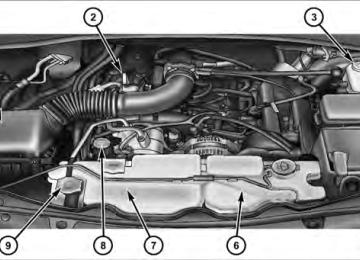
ENGINE BLOCK HEATER — IF EQUIPPED The engine block heater warms the engine, and permits quicker starts in cold weather. Connect the cord to a standard 110-115 Volt AC electrical outlet with a grounded three-wire extension cord. The engine block heater cord is found under the hood clipped to the heater line on the left side of the engine. The engine block heater must be plugged in at least one hour to have an adequate warming effect on the engine.
WARNING!
Remember to disconnect the engine block heater cord before driving. Damage to the 110-115 Volt AC electrical cord could cause electrocution.
294 STARTING AND OPERATING AUTOMATIC TRANSMISSION
CAUTION!
a complete stop.
Damage to the transmission may occur if the follow- ing precautions are not observed: • Shift into PARK only after the vehicle has come to • Shift into or out of REVERSE only after the vehicle has come to a complete stop and the engine is at idle speed. • Do not shift from REVERSE, PARK, or NEUTRAL into any forward gear when the engine is above idle speed. • Before shifting into any gear, make sure your foot
is firmly on the brake pedal.
WARNING!
• It is dangerous to move the shift lever out of PARK or NEUTRAL if the engine speed is higher than idle speed. If your foot is not firmly on the brake pedal, the vehicle could accelerate quickly forward or in REVERSE. You could lose control of the vehicle and hit someone or something. Only shift into gear when the engine is idling normally and when your foot is firmly on the brake pedal. • Never leave children alone in a vehicle. Leaving unattended in a vehicle is dangerous for a number of reasons. A child or others could be seriously or fatally injured. A child could operate power win- dows, other controls or move the vehicle.
Key Ignition Park Interlock This vehicle is equipped with a Key Ignition Park Inter- lock which requires the shift lever to be placed in PARK prior to rotating the key to the LOCK position. The key can only be removed from the ignition when the ignition is in the LOCK position. Once the key is removed, the shift lever is locked in PARK. Brake/Transmission Interlock System This vehicle is equipped with a Brake Transmission Shift Interlock System (BTSI) that holds the shift lever in the PARK position when the ignition switch is in the LOCK position. To move the shift lever out of the PARK position, the ignition switch must be turned to the ON or START position (engine running or not) and the brake pedal must be pressed.
STARTING AND OPERATING 295
Four–Speed Automatic Transmission – 3.7L Engine
NOTE: Under extreme cold temperatures (-10°F (-23°C) and when in DRIVE, transmission operation may be briefly limited to only second gear operation. Normal operation will resume once the transmission temperature has risen to a suitable level.
296 STARTING AND OPERATING Shifting from DRIVE to PARK or REVERSE should be done only after the accelerator pedal is released and the vehicle is stopped. Be sure to keep your foot on the brake when moving the shift lever between these gears.
Shift Lever
Gear Ranges DO NOT race the engine when shifting from PARK or NEUTRAL position into another gear range. PARK This range supplements the parking brake by locking the transmission. The engine can be started in this range. Never use PARK while the vehicle is in motion. Apply the parking brake when leaving the vehicle in this range. Always apply the parking brake first, then place the shift lever in the PARK position.
WARNING!
• Never use the PARK position as a substitute for the parking brake. Always apply the parking brake fully when parked to guard against vehicle movement and possible injury or damage.
(Continued)
WARNING! (Continued)
• It is dangerous to move the shift lever out of PARK or NEUTRAL if the engine speed is higher than idle speed. If your foot is not firmly on the brake pedal, the vehicle could accelerate quickly forward or in REVERSE. You could lose control of the vehicle and hit someone or something. Only shift into gear when the engine is idling normally and when your right foot is firmly on the brake pedal.
REVERSE This range is for moving the vehicle backward. Use only after the vehicle has come to a complete stop. NEUTRAL This range is used when vehicle is standing for pro- longed periods with engine running. Engine may be started in this range. Set the parking brake and shift the transmission into PARK if you must leave the vehicle.
STARTING AND OPERATING 297
NOTE: Towing the vehicle, coasting, or driving for any other reason with shift lever in NEUTRAL can result in severe transmission damage. Refer to “Recreational Tow- ing” in “Starting and Operating” and “Towing a Disabled Vehicle” in “What To Do In Emergencies” for further information. DRIVE This range is used for most city and highway driving. 2 (Second) This range is used for moderate grades and to assist braking on dry pavement or in mud and snow. Begins at a stop in low gear with automatic upshift to second gear. Will not shift into third gear. 1 (First) This range is used for hard pulling at low speeds in mud, sand, snow, or on steep grades. Begins and stays in low gear with no upshift. Provides engine compression brak- ing at low speeds.(48 km/h)
298 STARTING AND OPERATING Overdrive Operation The overdrive automatic transmission contains an elec- tronically controlled fourth gear (OVERDRIVE). The transmission will automatically shift from third gear into OVERDRIVE if the following conditions are present: • the shift lever is in DRIVE • vehicle speed is above approximately 30 mph • the TOW/HAUL button has not been activated The transmission will downshift from OVERDRIVE to DRIVE if the accelerator pedal is fully pressed at vehicle speeds above approximately 35 mph (56 km/h). When To Use TOW/HAUL Mode When driving in hilly areas, towing a trailer, carrying a heavy load, etc., and frequent transmission shifting oc- curs, press the TOW/HAUL button. This will improve
performance and reduce the potential for transmission overheating or failure due to excessive shifting. When operating in TOW/HAUL mode, the transmission will shift into third gear. NOTE: The TOW/HAUL mode locks out Overdrive.
Tow/Haul Button
The “TOW/HAUL Indicator Light” will illuminate in the instrument cluster to indicate when the switch has been activated. Pressing the switch a second time restores normal operation. If the TOW/HAUL mode is desired, the switch must be pressed each time the engine is started. Transmission Limp Home Mode Transmission function is monitored for abnormal condi- tions. If a condition is detected that could result in transmission damage, the Transmission Limp Home Mode will be engaged. In this mode, the transmission will remain in second gear in any forward driving range. To reset the transmission, use the following procedure: 1. Stop the vehicle. 2. Move the shift lever to the PARK position. 3. Turn the engine off and turn the key to the LOCK position.
STARTING AND OPERATING 299
4. Wait approximately 10 seconds, then restart the en- gine. 5. Move the shift lever to the desired gear range. If the problem is no longer detected, the transmission will return to normal operation. If the problem persists, PARK, REVERSE, and NEUTRAL will continue to oper- ate. Only second gear range will operate in the DRIVE position. Have the transmission checked at your autho- rized dealer as soon as possible. Torque Converter Clutch A feature designed to improve fuel economy has been added to the automatic transmission of this vehicle. A clutch within the torque converter engages automatically at calibrated speeds. This may result in a slightly differ- ent feeling or response during normal operation in high gear. When the vehicle speed drops or during accelera- tion, the clutch automatically and smoothly disengages.300 STARTING AND OPERATING Five–Speed Automatic Transmission – 4.0L Engine The electronically controlled transmission provides a precise shift schedule. The transmission electronics are self-calibrating; therefore, the first few shifts on a new vehicle may be somewhat abrupt. This is a normal condition and precision shifts will develop within a few hundred miles/kilometers.
Gear Ranges
NOTE: After selecting any gear range, wait a moment to allow the selected gear to engage before accelerating. This is especially important when the engine is cold. If there is a need to restart the engine, be sure to cycle the key to the LOCK position before restarting. Transmission gear engagement may be delayed after restarting the engine if the key is not cycled to the LOCK position first. PARK This range supplements the parking brake by locking the transmission. The engine can be started in this range. Never use PARK while the vehicle is in motion. Apply the parking brake when leaving the vehicle in this range. Always apply the parking brake first, then place the shift lever in the PARK position.
Shift Lever
WARNING!
• Never use the PARK position as a substitute for the parking brake. Always apply the parking brake fully when parked to guard against vehicle movement and possible injury or damage. • It is dangerous to move the shift lever out of PARK or NEUTRAL if the engine speed is higher than idle speed. If your foot is not firmly on the brake pedal, the vehicle could accelerate quickly forward or in REVERSE. You could lose control of the vehicle and hit someone or something. Only shift into gear when the engine is idling normally and when your right foot is firmly on the brake pedal.
REVERSE This range is for moving the vehicle backward. Use this range only after the vehicle has come to a complete stop.
STARTING AND OPERATING 301
NEUTRAL This range is used when vehicle is standing for pro- longed periods with engine running. Engine may be started in this range. Set the parking brake if you must leave the vehicle. NOTE: Towing the vehicle, coasting, or driving for any other reason with the shift lever in NEUTRAL can result in severe transmission damage. Refer to “Recreational Towing” in “Starting and Operating” and “Towing a Disabled Vehicle” in “What To Do In Emergencies” for further information. DRIVE This range is used for most city and highway driving. Electronic Range Select (ERS) Operation The Electronic Range Select (ERS) shift control allows you to move the shift lever left (-) or right (+) when the shift lever is in the DRIVE position, allowing the selection of the desired top gear. For example, if the driver shifts
302 STARTING AND OPERATING the transmission into third gear, the transmission will never shift above third gear, but can shift down into second gear or first gear, when needed.
WARNING!
Do not downshift for additional engine braking on a slippery surface. The drive wheels could lose their grip and the vehicle could skid.
1-3
1-2
Screen Display Actual Gear(s) Allowed NOTE: To select the proper gear position for maximum deceleration (engine braking), move the shift lever to the left “D (-)” and hold it there. The transmission will shift to the range from which the vehicle can best be slowed down.
1-4
1-5
Overdrive Operation The overdrive automatic transmission contains an elec- tronically controlled fifth gear (OVERDRIVE). The trans- mission will automatically shift from fourth gear to OVERDRIVE if the following conditions are present: • the shift lever is in DRIVE • the engine coolant has reached normal operating tem- • the vehicle speed is above approximately 30 mph • the transmission has
reached normal operating
(48 km/h)
perature
temperature
If the vehicle is started in extremely cold tem- NOTE: peratures, the transmission may not shift into OVER- DRIVE and will automatically select the most desirable gear for operation at this temperature. Normal operation will resume when the transmission fluid temperature has
risen to a suitable level. Refer to the “Note” under “Torque Converter Clutch” later in this section. During cold temperature operation, you may notice delayed upshifts depending on engine and transmission temperature. This feature improves the warm up time of the engine and transmission. During cold temperature operation, the transmission may not downshift from second gear into first gear after the initial first to second gear upshift. Transmission Limp Home Mode Transmission function is monitored for abnormal condi- tions. If a condition is detected that could result in transmission damage, the Transmission Limp Home Mode will be engaged. In this mode, the transmission will remain in the current gear until the vehicle is brought to a stop.
STARTING AND OPERATING 303
To reset the transmission, use the following procedure: 1. Stop the vehicle. 2. Move the shift lever to the PARK position. 3. Turn the engine off and turn the key to the LOCK position. 4. Wait approximately 10 seconds, then restart the en- gine. 5. Move the shift lever to the desired gear range. If the problem is no longer detected, the transmission will return to normal operation. If the problem persists, PARK, REVERSE, and NEUTRAL will continue to oper- ate. Only second gear will operate in the DRIVE position. Have the transmission checked at your authorized dealer as soon as possible.304 STARTING AND OPERATING Torque Converter Clutch A feature designed to improve fuel economy has been included in the automatic transmission on your vehicle. A clutch within the torque converter engages automati- cally at a calibrated speed at light throttle. It engages at higher speeds under heavier acceleration. This may re- sult in a slightly different feeling or response during normal operation in high gear. When the vehicle speed drops below a calibrated speed, or during acceleration, the clutch automatically and smoothly disengages. If the vehicle has not been driven in several NOTE: days, the first few seconds of operation after shifting the transmission into gear may seem sluggish. This is due to the fluid partially draining from the torque converter into the transmission. This condition is normal and will not cause damage to the transmission. The torque converter will refill within five seconds of starting the engine.
FOUR-WHEEL DRIVE OPERATION — IF EQUIPPED
Single-Speed Part-Time Transfer Case
Operating Information/Precautions The transfer case is operated by the transfer case switch (located on the center console).
Transfer Case Switch
The electronically shifted transfer case provides two mode positions: • Two-wheel drive high range (2WD) • Four-wheel drive high range (4WD LOCK) The electronically shifted transfer case is designed to be driven in the two-wheel drive position (2WD) for normal street and highway conditions (dry hard surfaced roads). When additional traction is required, the transfer case 4WD LOCK position can be used to lock the front and rear driveshafts together and force the front and rear wheels to rotate at the same speed. This is accomplished by rotating the transfer case switch to the desired posi- tion. Refer to “Shifting Procedure” for specific shifting instructions. The 4WD LOCK position is designed for loose, slippery road surfaces only.
STARTING AND OPERATING 305
CAUTION!
• Driving in the 4WD LOCK position on dry hard surfaced roads may cause increased tire wear and damage to the driveline components. • Do not attempt to make a shift while only the front or rear wheels are spinning. Shifting while only the front or rear wheels are spinning can cause damage to the transfer case.
Proper operation of four-wheel drive vehicles depends on tires of equal size, type and circumference on each wheel. Any difference in tire size can cause damage to the transfer case. Tire rotation schedule should be followed to balance tire wear. Since four-wheel drive provides improved traction, there is a tendency to exceed safe turning and stopping speeds. Do not go faster than road conditions permit.
306 STARTING AND OPERATING Shifting Procedure – Electronically Shifted Transfer Case
If any of the requirements to select a new NOTE: transfer case position have not been met, the transfer case will not shift. The “4WD Indicator Light” (located in the display under the tachometer) will flash until all the requirements for the selected position have been met. To retry a shift, return the control knob back to the original position, make certain all shift requirements have been met, wait five seconds and try the shift again. 2WD⇔ 4WD LOCK Rotate the transfer case switch to the desired position. Shifts between 2WD and 4WD LOCK can be done with the vehicle stopped or in motion. With the vehicle in motion, the transfer case will engage/disengage faster if
you momentarily release the accelerator pedal after turn- ing the switch. If the vehicle is stopped, the ignition key must be in the ON position with the engine either RUNNING or OFF. This shift cannot be completed if the key is in the ACC position. NOTE: • The four-wheel drive system will not allow shifts between 2WD/4WD LOCK if the front and/or rear wheels are spinning (no traction). In this situation, the “4WD Indicator Light” (located in the display under the tachometer) will flash. At this time, reduce speed and stop spinning the wheels to complete the shift. • Delayed shifting out of 4WD LOCK may be experi- enced due to uneven tire wear, low tire pressure, or excessive loading.
ON-ROAD DRIVING TIPS Utility vehicles have higher ground clearance and a narrower track to make them capable of performing in a wide variety of off-road applications. Specific design characteristics give them a higher center of gravity than ordinary cars. An advantage of the higher ground clearance is a better view of the road, allowing you to anticipate problems. They are not designed for cornering at the same speeds as conventional two-wheel drive vehicles any more than low-slung sports cars are designed to perform satisfacto- rily in off-road conditions. If at all possible, avoid sharp turns or abrupt maneuvers. As with other vehicles of this type, failure to operate this vehicle correctly may result in loss of control or vehicle rollover.
POWER STEERING The standard power steering system will give you good vehicle response and increased ease of maneuverability
STARTING AND OPERATING 307
in tight spaces. The system will provide mechanical steering capability if power assist is lost. If for some reason the power assist is interrupted, it will still be possible to steer your vehicle. Under these condi- tions, you will observe a substantial increase in steering effort, especially at very low vehicle speeds and during parking maneuvers. NOTE: • Increased noise levels at the end of the steering wheel travel are considered normal and do not indicate that there is a problem with the power steering system. • Upon initial start-up in cold weather, the power steer- ing pump may make noise for a short amount of time. This is due to the cold, thick fluid in the steering system. This noise should be considered normal, and it does not in any way damage the steering system.308 STARTING AND OPERATING
WARNING!
Continued operation with reduced power steering assist could pose a safety risk to yourself and others. Service should be obtained as soon as possible.
CAUTION!
Prolonged operation of the steering system at the end of the steering wheel travel will increase the steering fluid temperature and it should be avoided when possible. Damage to the power steering pump may occur.
Power Steering Fluid Check Checking the power steering fluid level at a defined service interval is not required. The fluid should only be checked if a leak is suspected, abnormal noises are
apparent, and/or the system is not functioning as antici- pated. Coordinate inspection efforts through an autho- rized dealer.
CAUTION!
Do not use chemical flushes in your power steering system as the chemicals can damage your power steering components. Such damage is not covered by the New Vehicle Limited Warranty.
WARNING!
Fluid level should be checked on a level surface and with the engine off to prevent injury from moving parts and to ensure accurate fluid level reading. Do not overfill. Use only manufacturer’s recommended power steering fluid.
If necessary, add fluid to restore to the proper indicated level. With a clean cloth, wipe any spilled fluid from all surfaces. Refer to “Fluids, Lubricants, and Genuine Parts” in “Maintaining Your Vehicle” for further information.
PARKING BRAKE Before leaving the vehicle, make sure that the parking brake is fully applied. Also, be certain to leave the transmission in PARK. The parking brake lever is located in the center console. To apply the parking brake, pull the lever up as firmly as possible. To release the parking brake, pull the lever up slightly, press the center button, then lower the lever completely.
STARTING AND OPERATING 309
Parking Brake
When the parking brake is applied with the ignition switch ON, the “Brake Warning Light” in the instrument cluster will illuminate.
310 STARTING AND OPERATING NOTE: • When the parking brake is applied and the transmis- sion is placed in gear, the “Brake Warning Light” will flash. If vehicle speed is detected, a chime will sound to alert the driver. Fully release the parking brake before attempting to move the vehicle. • This light only shows that the parking brake is ap- plied. It does not show the degree of brake application. When parking on a hill, it is important to turn the front wheels toward the curb on a downhill grade and away from the curb on an uphill grade. Apply the parking brake before placing the shift lever in PARK, otherwise the load on the transmission locking mechanism may make it difficult to move the shift lever out of PARK. The parking brake should always be applied whenever the driver is not in the vehicle.
WARNING!
• Never use the PARK position as a substitute for the parking brake. Always apply the parking brake fully when parked to guard against vehicle movement and possible injury or damage. • Never leave children alone in a vehicle. Leaving unattended children in a vehicle is dangerous for a number of reasons. A child or others could be seriously or fatally injured. • Do not leave the key in the ignition. A child could operate power windows, other controls, or move the vehicle. • Be sure the parking brake is fully disengaged before driving; failure to do so can lead to brake failure and a collision.
(Continued)
WARNING! (Continued)
• Always fully apply the parking brake when leav- ing your vehicle or it may roll and cause damage or injury. Also, be certain to leave the transmission in PARK. Failure to do so may cause the vehicle to roll and cause damage or injury.
CAUTION!
If the “Brake Warning Light” remains on with the parking brake released, a brake system malfunction is indicated. Have the brake system serviced by an authorized dealer immediately.
ANTI-LOCK BRAKE SYSTEM The Anti-Lock Brake System (ABS) is designed to aid the driver in maintaining vehicle control under adverse braking conditions. The system operates with a separate
STARTING AND OPERATING 311
computer to modulate hydraulic pressure, to prevent wheel lock-up and help avoid skidding on slippery surfaces. All vehicle wheels and tires must be the same size and type, and tires must be properly inflated, to produce accurate signals for the computer.WARNING!
Significant over or under-inflation of tires or mixing sizes of tires or wheels on the vehicle can lead to loss of braking effectiveness.
The ABS conducts a low-speed self-test at about 12 mph (20 km/h). If you have your foot lightly on the brake while this test is occurring, you may feel slight pedal movement. The movement can be more apparent on ice and snow. This is normal.
312 STARTING AND OPERATING The ABS pump motor runs during the self-test at 12 mph (20 km/h) and during an ABS stop. The pump motor makes a low humming noise during operation, which is normal.
WARNING!
• Pumping of the Anti-Lock Brakes will diminish their effectiveness and may lead to a collision. Pumping makes the stopping distance longer. Just press firmly on your brake pedal when you need to slow down or stop. • The ABS cannot prevent the natural laws of phys- ics from acting on the vehicle, nor can it increase braking or steering efficiency beyond that af- forded by the condition of the vehicle brakes and tires or the traction afforded.
WARNING! (Continued) • The ABS cannot prevent collisions,
including those resulting from excessive speed in turns, following another vehicle too closely, or hydro- planing. • The capabilities of an ABS equipped vehicle must never be exploited in a reckless or dangerous manner, which could jeopardize the user’s safety or the safety of others.
CAUTION!
The ABS is subject to possible detrimental effects of electronic interference caused by improperly in- stalled aftermarket radios or telephones.
(Continued)
NOTE: During severe braking conditions, a pulsing sensation may occur and a clicking noise will be heard. This is normal, indicating that the ABS is functioning.
• Do not “ride” the brakes by resting your foot on the pedal. This could overheat the brakes and result in longer stopping dis- unpredictable braking action, tances, or brake damage. • When descending mountains or hills, repeated brak- ing can cause brake fade with loss of braking control. Avoid repeated heavy braking by downshifting the transmission or locking out overdrive whenever pos- sible. • Engines may idle at higher speeds during warm-up, which could cause rear wheels to spin and result in loss of vehicle control. Be especially careful while driving on slippery roads, in close-quarter maneuver- ing, parking, or stopping. • Do not drive too fast for road conditions, especially when roads are wet or slushy. A wedge of water can
STARTING AND OPERATING 313
build up between the tire tread and the road. This hydroplaning action can cause loss of traction, braking ability, and control. • After going through deep water or a car wash, brakes may become wet, resulting in decreased performance and unpredictable braking action. Dry the brakes by gentle, intermittent pedal action while driving at very slow speeds.ELECTRONIC BRAKE CONTROL SYSTEM Your vehicle is equipped with an advanced electronic brake control system that includes an Anti-Lock Brake System (ABS), Traction Control System (TCS), Brake Assist System (BAS), Electronic Roll Mitigation (ERM) and Electronic Stability Control (ESC). All five systems work together to enhance vehicle stability and control in various driving conditions and are commonly referred to as ESC.
314 STARTING AND OPERATING Anti-Lock Brake System (ABS)
This system aids the driver in maintaining vehicle control under adverse braking conditions. The system controls hydraulic brake pressure to prevent wheel lockup and help avoid skidding on slippery surfaces during braking. Refer to “Anti-Lock Brake System” in “Starting and Operating” for further information.
WARNING!
The Anti-Lock Brake System (ABS) cannot prevent the natural laws of physics from acting on the ve- hicle, nor can it increase the traction afforded by prevailing road conditions. ABS cannot prevent col- lisions, including those resulting from excessive speed in turns, driving on very slippery surfaces, or hydroplaning. The capabilities of an ABS-equipped vehicle must never be exploited in a reckless or dangerous manner which could jeopardize the user’s safety or the safety of others.
Traction Control System (TCS)
This system monitors the amount of wheel spin of each of the driven wheels. If wheel spin is detected, brake pressure is applied to the slipping wheel(s) and engine power is reduced to provide enhanced acceleration and stability. A feature of the TCS system functions similar to
a limited slip differential and controls the wheel spin across a driven axle. If one wheel on a driven axle is spinning faster than the other, the system will apply the brake of the spinning wheel. This will allow more engine torque to be applied to the wheel that is not spinning. This feature remains active even if TCS and ESC are in the “Partial Off” mode. Refer to “Electronic Stability Control (ESC)” in this section for further information. Brake Assist System (BAS) The BAS is designed to optimize the vehicle’s braking capability during emergency braking maneuvers. The system detects an emergency braking situation by sens- ing the rate and amount of brake application and then applies optimum pressure to the brakes. This can help reduce braking distances. The BAS complements the Anti-Lock Brake System (ABS). Applying the brakes very quickly results in the best BAS assistance. To receive the benefit of the system, you must apply continuous brak- ing pressure during the stopping sequence. Do not
STARTING AND OPERATING 315
reduce brake pedal pressure unless braking is no longer desired. Once the brake pedal is released, the BAS is deactivated.WARNING!
The Brake Assist System (BAS) cannot prevent the natural laws of physics from acting on the vehicle, nor can it increase the traction afforded by prevailing road conditions. BAS cannot prevent collisions, in- cluding those resulting from excessive speed in turns, driving on very slippery surfaces, or hydro- planing. The capabilities of a BAS-equipped vehicle must never be exploited in a reckless or dangerous manner which could jeopardize the user’s safety or the safety of others.
316 STARTING AND OPERATING Electronic Roll Mitigation (ERM) This system anticipates the potential for wheel lift by monitoring the driver’s steering wheel input and the speed of the vehicle. When ERM determines that the rate of change of the steering wheel angle and vehicles speed are sufficient to potentially cause wheel lift, it applies the appropriate brake and may reduce engine power to lessen the chance that wheel lift will occur. ERM will only intervene during very severe or evasive driving maneu- vers. ERM can only reduce the chance of wheel lift occurring during severe or evasive driving maneuvers. It can not prevent wheel lift due to other factors such as road conditions, leaving the roadway, striking objects and/or other vehicles.
WARNING!
Many factors, such as vehicle loading, road condi- tions and driving conditions, influence the chance that wheel lift or rollover may occur. ERM cannot prevent all wheel lift or rollovers, especially those that involve leaving the roadway or striking objects or other vehicles. The capabilities of an ERM- equipped vehicle must never be exploited in a reck- less or dangerous manner which could jeopardize the user’s safety or the safety of others.
Electronic Stability Control (ESC)
This system enhances directional control and stability of the vehicle under various driving conditions. ESC cor- rects for oversteering or understeering of the vehicle by applying the brake of the appropriate wheel to assist in
counteracting the oversteer or understeer condition. En- gine power may also be reduced to help the vehicle maintain the desired path. ESC uses sensors in the vehicle to determine the vehicle path intended by the driver and compares it to the actual path of the vehicle. When the actual path does not match the intended path, ESC applies the brake of the appro- priate wheel to assist in counteracting the oversteer or understeer condition. • Oversteer - when the vehicle is turning more than • Understeer - when the vehicle is turning less than
appropriate for the steering wheel position.
appropriate for the steering wheel position.
The “ESC Activation/Malfunction Indicator Light” lo- cated in the instrument cluster will start to flash as soon as the tires lose traction and the ESC system becomes active. The “ESC Activation/Malfunction Indicator
STARTING AND OPERATING 317
Light” also flashes when the TCS is active. If the “ESC Activation/Malfunction Indicator Light” begins to flash during acceleration, ease up on the accelerator and apply as little throttle as possible. Be sure to adapt your speed and driving to the prevailing road conditions.WARNING!
The Electronic Stability Control (ESC) cannot pre- vent the natural laws of physics from acting on the vehicle, nor can it increase the traction afforded by prevailing road conditions. ESC cannot prevent col- lisions, including those resulting from excessive speed in turns, driving on very slippery surfaces, or hydroplaning. The capabilities of an ESC equipped vehicle must never be exploited in a reckless or dangerous manner which could jeopardize the user’s safety or the safety of others.
318 STARTING AND OPERATING ESC Operating Modes The ESC system has two available operating modes in 2WD, 4WD Part Time, 4WD Full Time, and on 2WD vehicles. ESC On This is the normal operating mode for ESC in 2WD, 4WD Part Time, 4WD Full Time, and on 2WD vehicles. When- ever the vehicle is started, the ESC system will be in this mode. This mode should be used for most all driving situations. ESC should only be turned off for specific reasons as noted below. Partial Off This mode is entered by momentarily pressing the “ESC Off” switch (located in the center stack lower switch bank). When in “Partial Off” mode, the TCS portion of ESC, except for the “limited slip” feature described in the TCS section, has been disabled and the “ESC Activation/ Malfunction Indicator Light” will be illuminated. All
other stability features of ESC function normally. This mode is intended to be used if the vehicle is in deep snow, sand or gravel conditions and more wheel spin than ESC would normally allow is required to gain traction. To turn ESC on again, momentarily press the “ESC Off” switch. This will restore the normal “ESC On” mode of operation. NOTE: To improve the vehicle’s traction when driving with snow chains, or starting off in deep snow, sand or gravel, it may be desirable to switch to the “Partial Off” mode by pressing the “ESC Off” switch. Once the situa- tion requiring ESC to be switched to the “Partial Off” mode is overcome, turn ESC back on by briefly pressing the “ESC Off” switch. This may be done while the vehicle is in motion.
ESC Activation/Malfunction Indicator Light and ESC OFF Indicator Light
The “ESC Activation/Malfunction Indicator Light” in the instrument cluster will come on when the ignition switch is turned to the ON position. It should go out with the engine running. If the “ESC Activation/Malfunction Indicator Light” comes on continuously with the engine running, a malfunction has been detected in the ESC system. If this light remains on after several ignition cycles, and the vehicle has been driven several miles (kilometers) at speeds greater than 30 mph (48 km/h), see your autho- rized dealer as soon as possible to have the problem diagnosed and corrected. The “ESC Activation/Malfunction Indicator Light” (lo- cated in the instrument cluster) starts to flash as soon as the tires lose traction and the ESC system becomes active. The “ESC Activation/Malfunction Indicator Light” also flashes when TCS is active. If the “ESC Activation/
STARTING AND OPERATING 319
Malfunction Indicator Light” begins to flash during ac- celeration, ease up on the accelerator and apply as little throttle as possible. Be sure to adapt your speed and driving to the prevailing road conditions. NOTE: • The “ESC Activation/Malfunction Indicator Light” and the “ESC OFF Indicator Light” come on momen- tarily each time the ignition switch is turned ON. • Each time the ignition is turned ON, the ESC system • The ESC system will make buzzing or clicking sounds when it is active. This is normal; the sounds will stop when ESC becomes inactive following the maneuver that caused the ESC activation.will be ON even if it was turned off previously.
The “ESC OFF Indicator Light” indicates the Electronic Stability Control (ESC) is off.
320 STARTING AND OPERATING TIRE SAFETY INFORMATION
Tire Markings
1 — U.S. DOT Safety Standards Code (TIN) 2 — Size Designation 3 — Service Description
4 — Maximum Load
5 — Maximum Pressure 6 — Treadwear, Traction and Temperature Grades
NOTE: • P (Passenger) - Metric tire sizing is based on U.S. design standards. P-Metric tires have the letter “P” molded into the sidewall preceding the size designa- tion. Example: P215/65R15 95H. • European-Metric tire sizing is based on European design standards. Tires designed to this standard have the tire size molded into the sidewall beginning with the section width. The letter ⬙P⬙ is absent from this tire size designation. Example: 215/65R15 96H. • LT (Light Truck) - Metric tire sizing is based on U.S. design standards. The size designation for LT-Metric tires is the same as for P-Metric tires except for the letters “LT” that are molded into the sidewall preced- ing the size designation. Example: LT235/85R16. • Temporary spare tires are high-pressure compact spares designed for temporary emergency use only.
Tires designed to this standard have the letter “T” molded into the sidewall preceding the size designa- tion. Example: T145/80D18 103M.
STARTING AND OPERATING 321
• High flotation tire sizing is based on U.S. design standards and it begins with the tire diameter molded into the sidewall. Example: 31x10.5 R15 LT.
Tire Sizing Chart
Size Designation:
EXAMPLE:
P = Passenger car tire size based on U.S. design standards ⴖ....blank....ⴖ = Passenger car tire based on European design standards LT = Light truck tire based on U.S. design standards T = Temporary spare tire 31 = Overall diameter in inches (in) 215 = Section width in millimeters (mm) 65 = Aspect ratio in percent (%)
— Ratio of section height to section width of tire
10.5 = Section width in inches (in) R = Construction code
— ⬙R⬙ means radial construction —⬙D⬙ means diagonal or bias construction
15 = Rim diameter in inches (in)
322 STARTING AND OPERATING
Service Description:
95 = Load Index
H = Speed Symbol
EXAMPLE:
— A numerical code associated with the maximum load a tire can carry
— A symbol indicating the range of speeds at which a tire can carry a load corresponding to its load index under certain operating conditions — The maximum speed corresponding to the speed symbol should only be achieved under specified operating conditions (i.e., tire pressure, vehicle loading, road conditions, and posted speed limits)
Load Identification:
ⴖ....blank....ⴖ = Absence of any text on the sidewall of the tire indicates a Standard Load (SL) tire Extra Load (XL) = Extra load (or reinforced) tire Light Load = Light load tire C, D, E = Load range associated with the maximum load a tire can carry at a specified pressure
Maximum Load — Maximum load indicates the maximum load this tire is designed to carry Maximum Pressure — Maximum pressure indicates the maximum permissible cold tire inflation pressure for this tire
Tire Identification Number (TIN) The TIN may be found on one or both sides of the tire, however, the date code may only be on one side. Tires with white sidewalls will have the full TIN, including the date code, located on the white sidewall side of the tire.
STARTING AND OPERATING 323
Look for the TIN on the outboard side of black sidewall tires as mounted on the vehicle. If the TIN is not found on the outboard side, then you will find it on the inboard side of the tire.DOT = Department of Transportation
— This symbol certifies that the tire is in compliance with the U.S. Department of Transportation tire safety standards and is approved for highway use
EXAMPLE:
DOT MA L9 ABCD 0301
MA = Code representing the tire manufacturing location (two digits) L9 = Code representing the tire size (two digits) ABCD = Code used by the tire manufacturer (one to four digits) 03 = Number representing the week in which the tire was manufactured (two digits)
—03 means the 3rd week.
01 = Number representing the year in which the tire was manufactured (two digits)
—01 means the year 2001
— Prior to July 2000, tire manufacturers were only required to have one number to represent the year in which the tire was manufactured. Example: 031 could represent the 3rd week of 1981 or 1991324 STARTING AND OPERATING Tire Terminology And Definitions
B-Pillar
Term
Cold Tire Pressure
Maximum Inflation Pressure
Recommended Inflation Pressure
Tire Placard
Definition
The vehicle B-Pillar is a structural member of the body located between the front and rear door (of a four-door vehicle) running from the sill to the roof. Cold tire inflation pressure is defined as the tire pressure after the vehicle has not been driven for at least 3 hours, or driven less than 1 mile (1.6 km) after sitting for a three hour period. Inflation pressure is measured in units of PSI (pounds per square inch) or KPa (kilopascals). The maximum inflation pressure is the maximum permissible cold tire inflation pressure for this tire. The max inflation pressure is molded into the sidewall. Vehicle manufacturer’s recommended tire inflation pressure as shown on the tire placard. A paper label permanently attached to the vehicle showing the vehicle’s loading capacity, the original equipment tire size and the recommended inflation pressure.
Tire Loading And Tire Pressure
Tire And Loading Information Placard
STARTING AND OPERATING 325
Tire Placard Location NOTE: The proper cold tire inflation pressure is listed on the driver’s side B-Pillar.
Tire and Loading Information Placard
Tire Placard Location
326 STARTING AND OPERATING
This placard tells you important information about the: 1) number of people that can be carried in the vehicle 2) total weight your vehicle can carry 3) tire size designed for your vehicle 4) cold tire inflation pressures for the front, rear, and spare tires. Loading The vehicle maximum load on the tire must not exceed the load carrying capacity of the tire on your vehicle. You will not exceed the tire’s load carrying capacity if you adhere to the loading conditions, tire size, and cold tire inflation pressures specified on the Tire and Loading Information placard and in the “Vehicle Loading” section of this manual. NOTE: Under a maximum loaded vehicle condition, gross axle weight ratings (GAWRs) for the front and rear
axles must not be exceeded. For further information on GAWRs, vehicle loading, and trailer towing, refer to “Vehicle Loading” in this section. To determine the maximum loading conditions of your vehicle, locate the statement “The combined weight of occupants and cargo should never exceed XXX lbs or XXX kg” on the Tire and Loading Information placard. The combined weight of occupants, cargo/luggage and trailer tongue weight (if applicable) should never exceed the weight referenced here. Steps For Determining Correct Load Limit 1. Locate the statement “The combined weight of occu- pants and cargo should never exceed XXX lbs or XXX kg” on your vehicle’s placard. 2. Determine the combined weight of the driver and passengers that will be riding in your vehicle.
STARTING AND OPERATING 327
NOTE: • The following table shows examples on how to calcu- late total load, cargo/luggage, and towing capacities of your vehicle with varying seating configurations and number and size of occupants. This table is for illustration purposes only and may not be accurate for the seating and load carry capacity of your vehicle. • For the following example, the combined weight of occupants and cargo should never exceed 865 lbs (392 kg).
3. Subtract the combined weight of the driver and pas- sengers from XXX lbs or XXX kg. 4. The resulting figure equals the available amount of cargo and luggage load capacity. For example, if “XXX” amount equals 1,400 lbs (635 kg) and there will be five 150 lb (68 kg) passengers in your vehicle, the amount of available cargo and luggage load capacity is 650 lbs (295 kg) (since 5 x 150 = 750, and 1400 – 750 = 650 lbs [295 kg]). 5. Determine the combined weight of luggage and cargo being loaded on the vehicle. That weight may not safely exceed the available cargo and luggage load capacity calculated in Step 4. 6. If your vehicle will be towing a trailer, load from your trailer will be transferred to your vehicle. Consult this manual to determine how this reduces the available cargo and luggage load capacity of your vehicle.
328 STARTING AND OPERATING
WARNING!
Safety
STARTING AND OPERATING 329
Overloading of your tires is dangerous. Overloading can cause tire failure, affect vehicle handling, and increase your stopping distance. Use tires of the recommended load capacity for your vehicle. Never overload them.
TIRES — GENERAL INFORMATION
Tire Pressure Proper tire inflation pressure is essential to the safe and satisfactory operation of your vehicle. Three primary areas are affected by improper tire pressure:
WARNING!
cause collisions.
sult in tire over-heating and failure.
• Improperly inflated tires are dangerous and can • Under-inflation increases tire flexing and can re- • Over-inflation reduces a tire’s ability to cushion shock. Objects on the road and chuckholes can cause damage that result in tire failure. • Over-inflated or under-inflated tires can affect vehicle handling and can fail suddenly, resulting in loss of vehicle control. • Unequal tire pressures can cause steering prob-
lems. You could lose control of your vehicle.
(Continued)
330 STARTING AND OPERATING
WARNING! (Continued)
• Unequal tire pressures from one side of the ve- hicle to the other can cause the vehicle to drift to the right or left. • Always drive with each tire inflated to the recom-
mended cold tire inflation pressure.
Economy Improper inflation pressures can cause uneven wear patterns to develop across the tire tread. These abnormal wear patterns will reduce tread life resulting in a need for earlier tire replacement. Under-inflation also increases tire fuel rolling consumption. Ride Comfort and Vehicle Stability Proper tire inflation contributes to a comfortable ride. Over-inflation produces a jarring and uncomfortable ride.
resistance
resulting
higher
in
Tire Inflation Pressures The proper cold tire inflation pressure is listed on the driver’s side “B” Pillar or rear edge of the driver’s side door. Some vehicles may have Supplemental Tire Pressure Information for vehicle loads that are less than the maximum loaded vehicle condition. These pressure con- ditions will be found in the “Supplemental Tire Pressure Information” section of this manual. The pressure should be checked and adjusted as well as inspecting for signs of tire wear or visible damage at least once a month. Use a good quality pocket-type gauge to check tire pressure. Do not make a visual judgement when determining proper inflation. Radial tires may look properly inflated even when they are under-inflated.
CAUTION!
After inspecting or adjusting the tire pressure, al- ways reinstall the valve stem cap. This will prevent moisture and dirt from entering the valve stem, which could damage the valve stem.
Inflation pressures specified on the placard are always “cold tire inflation pressure.” Cold tire inflation pressure is defined as the tire pressure after the vehicle has not been driven for at least three hours, or driven less than 1 mile (1.6 km) after a three hour period. The cold tire inflation pressure must not exceed the maximum infla- tion pressure molded into the tire sidewall. Check tire pressures more often if subject to a wide range of outdoor temperatures, as tire pressures vary with temperature changes.
STARTING AND OPERATING 331
Tire pressures change by approximately 1 psi (7 kPa) per 12°F (7°C) of air temperature change. Keep this in mind when checking tire pressure inside a garage, especially in the Winter. Example: If garage temperature = 68°F (20°C) and the outside temperature = 32°F (0°C) then the cold tire inflation pressure should be increased by 3 psi (21 kPa), which equals 1 psi (7 kPa) for every 12°F (7°C) for this outside temperature condition. Tire pressure may increase from 2 to 6 psi (13 to 40 kPa) during operation. DO NOT reduce this normal pressure build up or your tire pressure will be too low.332 STARTING AND OPERATING Tire Pressures For High Speed Operation The manufacturer advocates driving at safe speeds within posted speed limits. Where speed limits or condi- tions are such that the vehicle can be driven at high speeds, maintaining correct tire inflation pressure is very important. Increased tire pressure and reduced vehicle loading may be required for high-speed vehicle opera- tion. Refer to original equipment or an authorized tire dealer for recommended safe operating speeds, loading and cold tire inflation pressures.
WARNING!
High speed driving with your vehicle under maxi- mum load is dangerous. The added strain on your tires could cause them to fail. You could have a serious collision. Do not drive a vehicle loaded to the maximum capacity at continuous speeds above 75 mph (120 km/h).
Radial Ply Tires
WARNING!
Combining radial ply tires with other types of tires on your vehicle will cause your vehicle to handle poorly. The instability could cause a collision. Al- ways use radial ply tires in sets of four. Never combine them with other types of tires.
Cuts and punctures in radial tires are repairable only in the tread area because of sidewall flexing. Consult your authorized tire dealer for radial tire repairs. Spare Tire Matching Original Equipped Tire and Wheel – If Equipped Your vehicle may be equivalent with a spare tire and wheel in look and function as the original equipment tire and wheel found on the front or rear axle of your vehicle. This spare tire may be used in the tire rotation for your
vehicle. If your vehicle has this option refer to an authorized tire dealer for the recommended tire rotation pattern. If your vehicle is not equipped with an original equip- ment tire and wheel as a spare, a non-matching tempo- rary emergency use spare may be equipped with your vehicle. Temporary use spares are engineered to be used only with your vehicle. Your vehicle may be equipped with one of the following types of non-matching tempo- rary use spares; compact, full size, or limited-use. Do not install more than one non-matching temporary use spare tire/wheel on the vehicle at any given time.
CAUTION!
Because of the reduced ground clearance, do not take your vehicle through an automatic car wash with a compact, full size or limited-use temporary spare installed. Damage to the vehicle may result.
STARTING AND OPERATING 333
Compact Spare Tire – If Equipped The compact spare is for temporary emergency use only. You can identify if your vehicle is equipped with a compact spare by looking at the spare tire description on the Tire and Loading Information Placard located on the driver’s side door opening or on the sidewall of the tire. Compact spare tire descriptions begin with the letter “T” or “S” preceding the size designation. Example: T145/ 80D18 103M. T, S = Temporary Spare Tire Since this tire has limited tread life the original equip- ment tire should be repaired (or replaced) and reinstalled on your vehicle at the first opportunity. Do not install a wheel cover or attempt to mount a conventional tire on the compact spare wheel, since the wheel is designed specifically for the compact spare tire. Do not install more than one compact spare tire and wheel on the vehicle at any given time
334 STARTING AND OPERATING
WARNING!
Compact spares are for temporary emergency use only. With these spares, do not drive more than 50 mph (80 km/h). Temporary use spares have limited tread life. When the tread is worn to the tread wear indicators, the temporary use spare tire needs to be replaced. Be sure to follow the warnings, which apply to your spare. Failure to do so could result in spare tire failure and loss of vehicle control.
Full Size Spare – If Equipped The full size spare is for temporary emergency use only. This tire may look like the original equipped tire on the front or rear axle of your vehicle, but it is not. This spare tire may have limited tread life. When the tread is worn to the tread wear indicators, the temporary use full size spare tire needs to be replaced. Since it is not the same as
your original equipment tire, replace (or repair) the original equipment tire and reinstall on the vehicle at the first opportunity. Limited-Use Spare – If Equipped The limited-use spare tire is for temporary emergency use only. This tire is identified by a label located on the limited-use spare wheel. This label contains the driving limitations for this spare. This tire may look like the original equipped tire on the front or rear axle of your vehicle, but it is not. Installation of this limited-use spare tire affects vehicle handling. Since it is not the same as your original equipment tire, replace (or repair) the original equipment tire and reinstall on the vehicle at the first opportunity.
WARNING!
Limited-use spares are for emergency use only. In- stallation of this limited-use spare tire affects vehicle handling. With this tire, do not drive more than the speed listed on the limit-use spare wheel. Keep inflated to the cold tire inflation pressure listed on your Tire and Loading Information Placard located on the driver’s side door opening. Replace (or repair) the original equipment tire at the first opportunity and reinstall it on your vehicle. Failure to do so could result in loss of vehicle control.
STARTING AND OPERATING 335
Tire Spinning When stuck in mud, sand, snow, or ice conditions, do not spin your vehicle’s wheels faster than 30 mph (48 km/h) or for longer than 30 seconds continuously without stopping when you are stuck.
WARNING!
Fast spinning tires can be dangerous. Forces gener- ated by excessive wheel speeds may cause tire dam- age or failure. A tire could explode and injure some- one. Do not spin your vehicle’s wheels faster than 30 mph (48 km/h) or for more than 30 seconds continuously when you are stuck, and do not let anyone near a spinning wheel, no matter what the speed.
336 STARTING AND OPERATING Tread Wear Indicators Tread wear indicators are in the original equipment tires to help you in determining when your tires should be replaced.
1 — Worn Tire 2 — New Tire
These indicators are molded into the bottom of the tread grooves. They will appear as bands when the tread depth becomes 1/16 in (2 mm). When the tread is worn to the tread wear indicators, the tire should be replaced. Life Of Tire The service life of a tire is dependent upon varying factors including, but not limited to: • Driving style • Tire pressure • Distance driven
WARNING!
Tires and the spare tire should be replaced after six years, regardless of the remaining tread. Failure to follow this warning can result in sudden tire failure. You could lose control and have a collision resulting in serious injury or death.
STARTING AND OPERATING 337
It is recommended to replace the two front tires or two rear tires as a pair. Replacing just one tire can seriously affect your vehicle’s handling. If you ever replace a wheel, make sure that the wheel’s specifications match those of the original wheels. It is recommended you contact your original equipment or an authorized tire dealer with any questions you may have on tire specifications or capability. Failure to use equivalent replacement tires may adversely affect the safety, handling, and ride of your vehicle.Keep dismounted tires in a cool, dry place with as little exposure to light as possible. Protect tires from contact with oil, grease, and gasoline. Replacement Tires The tires on your new vehicle provide a balance of many characteristics. They should be inspected regularly for wear and correct cold tire inflation pressure. The manu- facturer strongly recommends that you use tires equiva- lent to the originals in size, quality and performance when replacement is needed. (Refer to the paragraph on “Tread Wear Indicators”). Refer to the “Tire and Loading Information” placard for the size designation of your tire. The Load Index and Speed Symbol for your tire will be found on the original equipment tire sidewall. See the Tire Sizing Chart example found in the Tire Safety Information section of this manual for more information relating to the Load Index and Speed Symbol of a tire.
338 STARTING AND OPERATING
WARNING!
• Do not use a tire, wheel size or rating other than that specified for your vehicle. Some combinations of unapproved tires and wheels may change sus- pension dimensions and performance characteris- tics, resulting in changes to steering, handling, and braking of your vehicle. This can cause unpredict- able handling and stress to steering and suspen- sion components. You could lose control and have a collision resulting in serious injury or death. Use only the tire and wheel sizes with load ratings approved for your vehicle. • Never use a tire with a smaller load index or capacity, other than what was originally equipped on your vehicle. Using a tire with a smaller load index could result in tire overloading and failure. You could lose control and have a collision.
(Continued)
WARNING! (Continued)
• Failure to equip your vehicle with tires having adequate speed capability can result in sudden tire failure and loss of vehicle control.
CAUTION!
Replacing original tires with tires of a different size may result in false speedometer and odometer read- ings.
TIRE CHAINS Use “Class S” chains or other traction aids that meet SAE Type “S” specifications. NOTE: Chains must be the proper size for the vehicle as recommended by the chain manufacturer.
CAUTION!
To avoid damage to your vehicle, tires or chains, observe the following precautions: • Because of limited chain clearance between tires and other suspension components, it is important that only chains in good condition are used. Bro- ken chains can cause serious vehicle damage. Stop the vehicle immediately if noise occurs that could suggest chain breakage. Remove the damaged parts of the chain before further use. • Install chains as tightly as possible and then • Do not exceed 45 mph (72 km/h). • Drive cautiously and avoid severe turns and large
retighten after driving about 1/2 mile (0.8 km).
bumps, especially with a loaded vehicle.
(Continued)
STARTING AND OPERATING 339
CAUTION! (Continued)
ment.
• Do not drive for a prolonged period on dry pave- • Observe the tire chain manufacturer’s instructions on method of installation, operating speed, and conditions for usage. Always use the lower sug- gested operating speed of the chain manufacturer if different than the speed recommended by the manufacturer.
These cautions apply to all chain traction devices, includ- ing link and cable (radial) chains. Tire chain use is permitted only on the rear tires. NOTE: The use of class “S” chains is permitted with P235/65R17 and P225/75R16 tires.
340 STARTING AND OPERATING
CAUTION!
CAUTION!
Do not use tire chains on vehicles equipped with tires other than P235/65R17 and P225/75R16 tires. There may not be adequate clearance for the chains and you are risking structural or body damage to your vehicle.
Proper operation of four-wheel drive vehicles de- pends on tires of equal size, type and circumference on each wheel. Any difference in tire size can cause damage to the transfer case. Tire rotation schedule should be followed to balance tire wear.
TIRE ROTATION RECOMMENDATIONS The tires on the front and rear of your vehicle operate at different loads and perform different steering, handling, and braking functions. For these reasons, they wear at unequal rates. These effects can be reduced by timely rotation of tires. The benefits of rotation are especially worthwhile with aggressive tread designs such as those on On/Off-Road type tires. Rotation will increase tread life, help to main- tain mud, snow, and wet traction levels, and contribute to a smooth, quiet ride.
Refer to the “Maintenance Schedule” for the proper maintenance intervals. More frequent rotation is permis- sible if desired. The reasons for any rapid or unusual wear should be corrected prior to rotation being per- formed. NOTE: The premium Tire Pressure Monitor System will automatically locate the pressure values displayed in the correct vehicle position following a tire rotation. The suggested rotation method is the “forward-cross” shown in the following diagram.
STARTING AND OPERATING 341
when the outside temperature decreases, the tire pressure will decrease. Tire pressure should always be set based on cold inflation tire pressure. This is defined as the tire pressure after the vehicle has not been driven for at least three hours, or driven less than 1 mile (1.6 km) after a three hour period. The cold tire inflation pressure must not exceed the maximum inflation pressure molded into the tire sidewall. Refer to “Tires – General Information” in “Starting and Operating” for information on how to properly inflate the vehicle’s tires. The tire pressure will also increase as the vehicle is driven. This is normal and there should be no adjustment for this increased pressure. The TPMS will warn the driver of a low tire pressure if the tire pressure falls below the low-pressure warning limit for any reason, including low temperature effects and natural pressure loss through the tire. The TPMS will continue to warn the driver of low tire pressure as long as the condition exists, and will not turnTire Rotation
TIRE PRESSURE MONITOR SYSTEM (TPMS) The Tire Pressure Monitor System (TPMS) will warn the driver of a low tire pressure based on the vehicle recom- mended cold placard pressure. The tire pressure will vary with temperature by about 1 psi (6.9 kPa) for every 12°F (6.5°C). This means that
342 STARTING AND OPERATING off until the tire pressure is at or above the recommended cold placard pressure. Once the low tire pressure warn- ing (Tire Pressure Monitoring Telltale Light) illuminates, you must increase the tire pressure to the recommended cold placard pressure in order for the “Tire Pressure Monitoring Telltale Light” to turn off. The system will automatically update and the “Tire Pressure Monitoring Telltale Light” will turn off once the system receives the updated tire pressures. The vehicle may need to be driven for up to 20 minutes above 15 mph (24 km/h) in order for the TPMS to receive this information. For example, your vehicle may have a recommended cold (parked for more than three hours) placard pressure of 33 psi (227 kPa). If the ambient temperature is 68°F (20°C) and the measured tire pressure is 28 psi (193 kPa), a temperature drop to 20°F (-7°C) will decrease the tire pressure to approximately 24 psi (165 kPa). This tire pressure is low enough to turn ON the “Tire Pressure Monitoring Telltale Light.” Driving the vehicle may cause
the tire pressure to rise to approximately 28 psi (193 kPa), but the “Tire Pressure Monitoring Telltale Light” will still be on. In this situation, the “Tire Pressure Monitoring Telltale Light” will turn off only after the tires are inflated to the vehicle’s recommended cold placard pressure value.
CAUTION!
• The TPMS has been optimized for the original equipment tires and wheels. TPMS pressures and warning have been established for the tire size equipped on your vehicle. Undesirable system operation or sensor damage may result when using replacement equipment that is not of the same size, type, and/or style. Aftermarket wheels can cause sensor damage. Do not use aftermarket tire seal- ants or balance beads if your vehicle is equipped with a TPMS, as damage to the sensors may result. (Continued)
CAUTION! (Continued)
• After inspecting or adjusting the tire pressure, always reinstall the valve stem cap. This will prevent moisture and dirt from entering the valve stem, which could damage the Tire Pressure Moni- toring Sensor.
NOTE: • The TPMS is not intended to replace normal tire care and maintenance, or to provide warning of a tire failure or condition. • The TPMS should not be used as a tire pressure gauge • Driving on a significantly under-inflated tire causes the tire to overheat and can lead to tire failure. Under-inflation also reduces fuel efficiency and tire tread life, and may affect the vehicle’s handling and stopping ability.
while adjusting your tire pressure.
STARTING AND OPERATING 343
• The TPMS is not a substitute for proper tire mainte- nance, and it is the driver’s responsibility to maintain correct tire pressure using an accurate tire pressure gauge, even if under-inflation has not reached the level to trigger illumination of the “Tire Pressure Monitoring Telltale Light.” • Seasonal temperature changes will affect tire pressure, and the TPMS will monitor the actual tire pressure in the tire.
Base System The Tire Pressure Monitor System (TPMS) uses wireless technology with wheel rim mounted electronic sensors to monitor tire pressure levels. Sensors, mounted to each wheel as part of the valve stem, transmit tire pressure readings to the receiver module. It is particularly important for you to check the NOTE: tire pressure in all of the tires on your vehicle monthly and to maintain the proper pressure.
344 STARTING AND OPERATING The TPMS consists of the following components: • Receiver Module • Four Tire Pressure Monitoring Sensors • Tire Pressure Monitoring Telltale Light The matching full-size spare wheel and tire assembly (if equipped) has a tire pressure monitoring sensor. The matching full-size spare can be used in place of any of the four road tires. The TPMS will only monitor the pressure in the full-size spare when it is used in place of a road tire. Otherwise, a spare with a pressure below the low- pressure limit will not cause the “Tire Pressure Monitor- ing Telltale Light” to illuminate or the chime to sound.
Tire Pressure Monitoring Low Pressure Warnings
The “Tire Pressure Monitoring Telltale Light” will illuminate in the instrument cluster and a chime will sound when tire pressure is low in one or more of the four active road tires. Should this occur, you should stop as soon as possible, check the inflation pressure of each tire on your vehicle, and inflate each tire to the vehicle’s recommended cold placard pressure value. Once the system receives the updated tire pres- sures, the system will automatically update and the “Tire Pressure Monitoring Telltale Light” will turn off. The vehicle may need to be driven for up to 20 minutes above 15 mph (24 km/h) in order for the TPMS to receive this information.
Check TPMS Warning When a system fault is detected, the “Tire Pressure Monitoring Telltale Light” will flash on and off for 75 seconds and then remain on solid. The system fault will also sound a chime. If the ignition key is cycled, this sequence will repeat, providing the system fault still exists. The “Tire Pressure Monitoring Telltale Light” will turn off when the fault condition no longer exists. A system fault can occur due to any of the following: 1. Jamming due to electronic devices or driving next to facilities emitting the same radio frequencies as the TPMS sensors. 2. Installing some form of aftermarket window tinting that affects radio wave signals. 3. Lots of snow or ice around the wheels or wheel housings. 4. Using tire chains on the vehicle.
STARTING AND OPERATING 345
5. Using wheels/tires not equipped with TPMS sensors. Vehicles With Full-Size Spare 1. The matching full-size spare wheel and tire assembly has a tire pressure monitoring sensor that can be moni- tored by the TPMS. 2. If you install the full-size spare in place of a road tire that has a pressure below the low-pressure warning limit, a chime will sound and the “TPMS Telltale Light” will turn on upon the next ignition key cycle. 3. Driving the vehicle for up to 20 minutes above 15 mph (24 km/h) will turn off the “TPMS Telltale Light,” as long as no tire pressure is below the low-pressure warning limit in any of the four active road tires.346 STARTING AND OPERATING Vehicles With Compact Spare 1. The compact spare tire does not have a tire pressure monitoring sensor. Therefore, the TPMS will not monitor the pressure in the compact spare tire. 2. If you install the compact spare tire in place of a road tire that has a pressure below the low-pressure warning limit, a chime will sound and the “TPMS Telltale Light” will turn on upon the next ignition key cycle. 3. After driving the vehicle for up to 20 minutes above 15 mph (24 km/h), the “TPMS Telltale Light” will flash on and off for 75 seconds and then remain on solid. 4. For each subsequent ignition key cycle, a chime will sound and the “TPMS Telltale Light” will flash on and off for 75 seconds and then remain on solid. 5. Once you repair or replace the original road tire and reinstall it on the vehicle in place of the compact spare, the TPMS will update automatically and the “TPMS
Telltale Light” will turn off, as long as no tire pressure is below the low-pressure warning limit in any of the four active road tires. The vehicle may need to be driven for up to 20 minutes above 15 mph (24 km/h) in order for the TPMS to receive this information. Premium System – If Equipped The Tire Pressure Monitor System (TPMS) uses wireless technology with wheel rim mounted electronic sensors to monitor tire pressure levels. Sensors, mounted to each wheel as part of the valve stem, transmit tire pressure readings to the receiver module. It is particularly important for you to check the NOTE: tire pressure in all of the tires on your vehicle monthly and to maintain the proper pressure. The TPMS consists of the following components: • Receiver Module • Four Tire Pressure Monitoring Sensors
wheel-wells)
• Three Trigger Modules (mounted in three of the four • Various Tire Pressure Monitoring System messages, which display in the Electronic Vehicle Information Center (EVIC)
• Tire Pressure Monitoring Telltale Light The matching full size spare wheel and tire assembly (if equipped) has a tire pressure monitoring sensor. The full size spare can be used in place of any of the four road tires. A spare with a pressure below the low-pressure limit will not cause the “Tire Pressure Monitoring Telltale Light” to illuminate or the chime to sound. However, it will cause a “SPARE LOW PRESSURE” message to display in the EVIC.
STARTING AND OPERATING 347
Tire Pressure Monitoring Low Pressure Warnings
The “Tire Pressure Monitoring Telltale Light” will illuminate in the instrument cluster and a chime will sound when tire pressure is low in one or more of the four active road tires. In addition, the Electronic Vehicle Information Center (EVIC) will display a graphic showing the pressure values of each tire with the low tire pressure values flashing.