- 2010 Dodge Dakota Owners Manuals
- Dodge Dakota Owners Manuals
- 2008 Dodge Dakota Owners Manuals
- Dodge Dakota Owners Manuals
- 2006 Dodge Dakota Owners Manuals
- Dodge Dakota Owners Manuals
- 2009 Dodge Dakota Owners Manuals
- Dodge Dakota Owners Manuals
- 2004 Dodge Dakota Owners Manuals
- Dodge Dakota Owners Manuals
- 2011 Dodge Dakota Owners Manuals
- Dodge Dakota Owners Manuals
- 2005 Dodge Dakota Owners Manuals
- Dodge Dakota Owners Manuals
- 2007 Dodge Dakota Owners Manuals
- Dodge Dakota Owners Manuals
- Download PDF Manual
-
• Do not use adhesive labels. These labels can peel • RES is a single CD player. Do not attempt to insert • Dual-media disc types (one side is a DVD, the other side is a CD) should not be used, and they can cause damage to the player.
a second CD if one is already loaded.
EJECT Button - Ejecting a CD
Press the EJECT button to eject the CD.
If you have ejected a disc and have not removed it within 10 seconds, it will be reloaded. If the CD is not removed, the radio will reinsert the CD but will not play it. A disc can be ejected with the radio and ignition OFF. NOTE: Ejecting with the ignition OFF is not allowed on convertible or soft-top models (if equipped). SEEK Button Press the right SEEK button for the next selection on the CD. Press the left SEEK button to return to the beginning of the current selection, or return to the beginning of the previous selection if the CD is within the first second of
the current selection. Pressing and holding the SEEK button will allow faster scrolling through the tracks in CD and MP3 modes. TIME Button Press this button to change the display from a large CD playing time display to a small CD playing time display. RW/FF Press and hold the FF (Fast Forward) button and the CD player will begin to fast forward until FF is released, or RW or another CD button is pressed. The RW (Reverse) button works in a similar manner. AM/FM Button Press the button to select either AM or FM mode.
UNDERSTANDING YOUR INSTRUMENT PANEL 217
SET/RND Button (Random Play Button) Press this button while the CD is playing to activate Random Play. This feature plays the selections on the compact disc in random order to provide an interesting change of pace. Press the right SEEK button to move to the next ran- domly selected track. Press the RND button a second time to stop Random Play. Notes on Playing MP3 Files The radio can play MP3 files; however, acceptable MP3
file recording media and formats are limited. When writing MP3 files, pay attention to the following restric- tions. Supported Media (Disc Types) The MP3 file recording media supported by the radio are CDDA, CD-R, CD-RW, MP3, and CDDA+MP3.218 UNDERSTANDING YOUR INSTRUMENT PANEL Supported Medium Formats (File Systems) The medium formats supported by the radio are ISO 9660
Level 1 and Level 2 and includes the Joliet extension. When reading discs recorded using formats other than ISO 9660 Level 1 and Level 2, the radio may fail to read files properly and may be unable to play the file nor- mally. UDF and Apple HFS formats are not supported. The radio uses the following limits for file systems: • Maximum number of folder levels: 8
• Maximum number of files: 255
• Maximum number of folders. (The radio display of file names and folder names is limited. For large numbers of files and/or folders, the radio may be unable to display the file name and folder name, and will assign a number instead. With a maximum number of files,exceeding 20 folders will result in this display. With in this 200 files, exceeding 50 folders will result display.) • Maximum number of characters in file/folder names: • Level 1: 12 (including a separator ⬙.⬙ and a three- • Level 2: 31 (including a separator ⬙.⬙ and a three-
character extension)
character extension)
Multisession disc formats are supported by the radio. Multisession discs may contain combinations of normal CD audio tracks and computer files (including MP3 files). Discs created with an option such as ⬙keep disc open after writing⬙ are most likely multisession discs. The use of multisession for CD audio or MP3 playback may result in longer disc loading times.
Supported MP3 File Formats The radio will recognize only files with the *.MP3 exten- sion as MP3 files. Non-MP3 files named with the *.MP3
extension may cause playback problems. The radio is designed to recognize the file as an invalid MP3 and will not play the file. When using the MP3 encoder to compress audio data to an MP3 file, the bit rate and sampling frequencies in the following table are supported. In addition, variable bit rates (VBR) are also supported. The majority of MP3 files use a 44.1 kHz sampling rate and a 192, 160, 128, 96 or VBR bit rate. MPEGBit Rate (kbps)
Sampling Fre- quency (kHz)
Specification
MPEG-1 Audio
Layer 3
48, 44.1, 32
320, 256, 224, 192, 160, 128, 112, 96, 80, 64, 56, 48, 40, 32
UNDERSTANDING YOUR INSTRUMENT PANEL 219
MPEG
Specification
Sampling Fre- quency (kHz)
MPEG-2 Audio
Layer 3
24, 22.05, 16
Bit Rate (kbps)
160, 128, 144, 112, 96, 80, 64, 56, 48, 40, 32, 24,
16, 8
ID3 Tag information for artist, song title, and album title are supported for version 1 ID3 tags. ID3 version 2 is not supported by the radios. Playlist files are not supported. MP3 Pro files are not supported. Playback of MP3 Files When a medium containing MP3 data is loaded, the radio checks all files on the medium. If the medium contains a lot of folders or files, the radio will take more time to start playing the MP3 files.
220 UNDERSTANDING YOUR INSTRUMENT PANEL Loading times for playback of MP3 files may be affected by the following: • Media - CD-RW media may take longer to load than • Medium formats - Multisession discs may take longer • Number of files and folders - Loading times will
to load than non-multisession discs
CD-R media
increase with more files and folders
To increase the speed of disc loading, it is recommended to use CD-R media and single-session discs. To create a single-session disc, enable the “Disc at Once” option before writing to the disc. Operation Instructions - Auxiliary Mode The auxiliary (AUX) jack is an audio input jack, which allows the user to plug in a portable device, such as an
MP3 player, or cassette player, and utilize the vehicle’s audio system to amplify the source and play through the vehicle speakers. Pressing the DISC/AUX button will change the mode to auxiliary device if the AUX jack is connected. NOTE: The AUX device must be turned on and the device’s volume set to proper level. If the AUX audio is not loud enough, turn the device’s volume up. If the AUX audio sounds distorted, turn the device’s volume down. TIME Button (Auxiliary Mode) Press this button to change the display to time of day. The time of day will display for five seconds (when ignition is OFF).
MEDIA CENTER 130 WITH SATELLITE RADIO (SALES CODE RES+RSC)
NOTE: The radio sales code is located on the lower right side of the radio faceplate.
UNDERSTANDING YOUR INSTRUMENT PANEL 221
Power Switch/Volume Control (Rotary) Push the ON/VOLUME control knob to turn on the radio. Push the ON/VOLUME control knob a second time to turn off the radio. Electronic Volume Control The electronic volume control turns continuously (360
degrees) in either direction without stopping. Turning the ON/VOLUME control knob to the right increases the volume and to the left decreases it. When the audio system is turned on, the sound will be set at the same volume level as last played. SEEK Buttons Press and release the SEEK buttons to search for the next listenable station in AM/FM mode. Press the right switch to seek up and the left switch to seek down. The radio will remain tuned to the new station until you make another selection. Holding either button will bypass stations without stopping until you release it.Media Center 130 (RES/RSC) Operating Instructions — Radio Mode
NOTE: The ignition switch must be in the ON or ACC position to operate the radio.
222 UNDERSTANDING YOUR INSTRUMENT PANEL Voice Command System (Radio) — If Equipped Refer to “Voice Command” in “Understanding The Fea- tures If Your Vehicle”. Voice Command Button Uconnect™ Phone — If Equipped Press this button to operate the Uconnect™ Phone feature (if equipped). Refer to “Uconnect™ Phone” in “Under- standing The Features If Your Vehicle”. If your vehicle is not equipped with or this feature is not available on your vehicle, a “Not Equipped With Uconnect Phone” message will display on the radio screen. Phone Button Uconnect™ Phone — If Equipped Press this button to operate the Uconnect™ Phone feature (if equipped). Refer to “Uconnect™ Phone” in “Under- standing The Features If Your Vehicle”.
If your vehicle is not equipped with or this feature is not available on your vehicle, a “Not Equipped With Uconnect Phone” message will display on the radio screen. TIME Button Press the TIME button to alternate display of the time and radio frequency. Clock Setting Procedure 1. Press and hold the TIME button until the hours blink. 2. Adjust the hours by turning the right side TUNE/ SCROLL control knob. 3. After adjusting the hours, press the right side TUNE/ SCROLL control knob to set the minutes. The minutes will begin to blink.
4. Adjust the minutes using the right side TUNE/ SCROLL control knob. Press the TUNE/SCROLL control knob to save time change. 5. To exit, press any button/knob or wait five seconds. The clock can also be set by pressing the SETUP button. For vehicles equipped with satellite radio, press the SETUP button, use the TUNE/SCROLL control to select SET CLOCK, and then follow the above procedure, starting at Step 2. For vehicles not equipped with satellite radio, press the SETUP button and then follow the above procedure, starting at Step 2. INFO Button Press the INFO button for an RDS station (one with call letters displayed). The radio will return a Radio Text message broadcast from an FM station (FM mode only).
UNDERSTANDING YOUR INSTRUMENT PANEL 223
RW/FF Pressing the RW (Rewind) or FF (Fast Forward) buttons causes the tuner to search for the next frequency in the direction of the arrows. This feature operates in either AM or FM frequencies. TUNE Control Turn the rotary TUNE/SCROLL control knob clockwise to increase or counterclockwise to decrease the frequency. Setting the Tone, Balance, and Fade Push the rotary TUNE/SCROLL control knob and BASS will display. Turn the TUNE/SCROLL control knob to the right or left to increase or decrease the bass tones. Push the rotary TUNE/SCROLL control knob a second time and MID will display. Turn the TUNE/SCROLL control knob to the right or left to increase or decrease the mid-range tones.
224 UNDERSTANDING YOUR INSTRUMENT PANEL Push the rotary TUNE/SCROLL control knob a third time and TREBLE will display. Turn the TUNE/SCROLL control knob to the right or left to increase or decrease the treble tones. Push the rotary TUNE/SCROLL control knob a fourth time and BALANCE will display. Turn the TUNE/ SCROLL control knob to the right or left to adjust the sound level from the right or left side speakers. Push the rotary TUNE/SCROLL control knob a fifth time and FADE will display. Turn the TUNE/SCROLL control knob to the left or right to adjust the sound level between the front and rear speakers. Push the rotary TUNE/SCROLL control knob again to exit setting tone, balance, and fade. MUSIC TYPE Button Pressing this button once will turn on the Music Type mode for five seconds. Pressing the MUSIC TYPE button
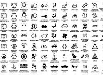
or turning the TUNE/SCROLL control knob within five seconds will allow the program format type to be se- lected. Many radio stations do not currently broadcast Music Type information. Toggle the MUSIC TYPE button to select the following format types:
Program Type
No program type or un-
defined
Adult Hits Classical
Classic Rock
College Country
Foreign Language
Information
16-Digit Character
Display
None
Adlt Hit Classicl Cls Rock College Country Language
Inform
Program Type
Jazz News
Nostalgia
Oldies
Personality
Public
Rhythm and Blues Religious Music Religious Talk
Rock Soft
Soft Rock
Soft Rhythm and Blues
Sports Talk
16-Digit Character
Display
Jazz News
Nostalga Oldies Persnlty Public R & B
Rel Musc Rel Talk
Rock Soft
Soft Rck Soft R&B
Sports Talk
UNDERSTANDING YOUR INSTRUMENT PANEL 225
Program Type
Top 40
Weather16-Digit Character
Display Top 40
WeatherBy pressing the SEEK button when the Music Type icon is displayed, the radio will be tuned to the next frequency station with the same selected Music Type name. The Music Type function only operates when in the FM mode. If a preset button is activated while in the Music Type (Program Type) mode, the Music Type mode will be exited and the radio will tune to the preset station. SETUP Button Pressing the SETUP button allows you to select between the following items: • Set Clock — Pressing the SELECT button will allow you to set the clock. Adjust the hours by turning the
226 UNDERSTANDING YOUR INSTRUMENT PANEL
TUNE/SCROLL control knob. After adjusting the hours, press the TUNE/SCROLL control knob to set the minutes. The minutes will begin to blink. Adjust the minutes using the right side TUNE/SCROLL control knob. Press the TUNE/SCROLL control knob to save time change.
AM/FM Button Press the button to select either AM or FM mode. SET/RND Button — To Set the Pushbutton Memory When you are receiving a station that you wish to commit to pushbutton memory, press the SET/RND button. The symbol SET 1 will now show in the display window. Select the button (1–6) you wish to lock onto this station and press and release that button. If a button is not selected within five seconds after pressing the SET/ RND button, the station will continue to play but will not be stored into pushbutton memory.
You may add a second station to each pushbutton by repeating the above procedure with this exception: Press the SET/RND button twice and SET 2 will show in the display window. Each button can be set for SET 1 and SET 2 in both AM and FM. This allows a total of 12 AM and 12 FM stations to be stored into pushbutton memory. The stations stored in SET 2 memory can be selected by pressing the pushbutton twice. Every time a preset button is used, a corresponding button number will display. Buttons 1 - 6
These buttons tune the radio to the stations that you commit to pushbutton memory (12 AM and 12 FM stations). DISC/AUX Button Pressing the DISC/AUX button will allow you to switch from AM/FM modes to DISC/AUX mode.Operation Instructions — CD MODE for CD and MP3 Audio Play NOTE: • The ignition switch must be in the ON or ACC • This radio is capable of playing compact discs (CD), recordable compact discs (CD-R), rewritable compact discs (CD-RW), compact discs with MP3 tracks and multisession compact discs with CD and MP3 tracks.
position to operate the radio.
Inserting Compact Disc(s) Gently insert one CD into the CD player with the CD label facing up. The CD will automatically be pulled into the CD player and the CD icon will illuminate on the radio display. If a CD does not go into the slot more than 1.0 in (2.5 cm), a disc may already be loaded and must be ejected before a new disc can be loaded.
UNDERSTANDING YOUR INSTRUMENT PANEL 227
If you insert a disc with the ignition ON and the radio ON, the unit will switch from radio to CD mode and begin to play when you insert the disc. The display will show the track number, and index time in minutes and seconds. Play will begin at the start of track 1.CAUTION!
away and jam the player mechanism.
• This CD player will accept 4–3/4 in (12 cm) discs only. The use of other sized discs may damage the CD player mechanism. • Do not use adhesive labels. These labels can peel • RES is a single CD player. Do not attempt to insert • Dual-media disc types (one side is a DVD, the other side is a CD) should not be used, and they can cause damage to the player.
a second CD if one is already loaded.
228 UNDERSTANDING YOUR INSTRUMENT PANEL EJECT Button - Ejecting a CD
Press the EJECT button to eject the CD.
If you have ejected a disc and have not removed it within 10 seconds, it will be reloaded. If the CD is not removed, the radio will reinsert the CD but will not play it. A disc can be ejected with the radio and ignition OFF. NOTE: Ejecting with the ignition OFF is not allowed on convertible or soft-top models (if equipped). SEEK Button Press the right SEEK button for the next selection on the CD. Press the left SEEK button to return to the beginning of the current selection, or return to the beginning of the previous selection if the CD is within the first second of
the current selection. Pressing and holding the SEEK button will allow faster scrolling through the tracks in CD and MP3 modes. TIME Button Press this button to change the display from a large CD playing time display to a small CD playing time display. RW/FF Press and hold FF (Fast Forward) and the CD player will begin to fast forward until FF is released or RW or another CD button is pressed. The RW (Reverse) button works in a similar manner. AM/FM Button Press the button to select either AM or FM mode.
SET/RND Button (Random Play Button) Press this button while the CD is playing to activate Random Play. This feature plays the selections on the compact disc in random order to provide an interesting change of pace. Press the right SEEK button to move to the next ran- domly selected track. Press the SET/RND button a second time to stop Ran- dom Play. Notes On Playing MP3 Files The radio can play MP3 files; however, acceptable MP3
file recording media and formats are limited. When writing MP3 files, pay attention to the following restric- tions. Supported Media (Disc Types) The MP3 file recording media supported by the radio are CDDA, CD-R, CD-RW, MP3, and CDDA+MP3.UNDERSTANDING YOUR INSTRUMENT PANEL 229
Supported Medium Formats (File Systems) The medium formats supported by the radio are ISO 9660
Level 1 and Level 2 and includes the Joliet extension. When reading discs recorded using formats other than ISO 9660 Level 1 and Level 2, the radio may fail to read files properly and may be unable to play the file nor- mally. UDF and Apple HFS formats are not supported. The radio uses the following limits for file systems: • Maximum number of folder levels: 8
• Maximum number of files: 255
• Maximum number of folders. (The radio display of file names and folder names is limited. For large numbers of files and/or folders, the radio may be unable to display the file name and folder name and will assign a number instead. With a maximum number of files,230 UNDERSTANDING YOUR INSTRUMENT PANEL
exceeding 20 folders will result in this display. With in this 200 files, exceeding 50 folders will result display.) • Maximum number of characters in file/folder names: • Level 1: 12 (including a separator ⬙.⬙ and a three- • Level 2: 31 (including a separator ⬙.⬙ and a three-
character extension)
character extension)
Multisession disc formats are supported by the radio. Multisession discs may contain combinations of normal CD audio tracks and computer files (including MP3 files). Discs created with an option such as ⬙keep disc open after writing⬙ are most likely multisession discs. The use of multisession for CD audio or MP3 playback may result in longer disc loading times.
Supported MP3 File Formats The radio will recognize only files with the *.MP3 exten- sion as MP3 files. Non-MP3 files named with the *.MP3
extension may cause playback problems. The radio is designed to recognize the file as an invalid MP3 and will not play the file. When using the MP3 encoder to compress audio data to an MP3 file, the bit rate and sampling frequencies in the following table are supported. In addition, variable bit rates (VBR) are also supported. The majority of MP3 files use a 44.1 kHz sampling rate and a 192, 160, 128, 96 or VBR bit rates.MPEG
Specification
Sampling Fre- quency (kHz)
MPEG-1 Audio
Layer 3
48, 44.1, 32
MPEG-2 Audio
Layer 3
24, 22.05, 16
Bit Rate (kbps)
320, 256, 224, 192, 160, 128, 112, 96, 80, 64, 56, 48, 40, 32
160, 128, 144, 112, 96, 80, 64, 56, 48, 40, 32, 24,16, 8
ID3 Tag information for artist, song title, and album title are supported for version 1 ID3 tags. ID3 version 2 is not supported by the radios. Playlist files are not supported. MP3 Pro files are not supported.
UNDERSTANDING YOUR INSTRUMENT PANEL 231
Playback of MP3 Files When a medium containing MP3 data is loaded, the radio checks all files on the medium. If the medium contains a lot of folders or files, the radio will take more time to start playing the MP3 files. Loading times for playback of MP3 files may be affected by the following: • Media - CD-RW media may take longer to load than • Medium formats - Multisession discs may take longer • Number of files and folders - Loading times will
to load than non-multisession discs
CD-R media
increase with more files and folders
To increase the speed of disc loading, it is recommended to use CD-R media and single-session discs. To create a single-session disc, enable the “Disc at Once” option before writing to the disc.
232 UNDERSTANDING YOUR INSTRUMENT PANEL LIST Button (CD Mode for MP3 Play) Pressing the LIST button will bring up a list of all folders on the disc. Scrolling up or down the list is done by turning the TUNE/SCROLL control knob. Selecting a folder by pressing the TUNE/SCROLL control knob will begin playing the files contained in that folder (or the next folder in sequence if the selection does not contain playable files). The folder list will time out after five seconds. INFO Button (CD Mode for MP3 Play) Pressing the INFO button repeatedly will scroll through the following TAG information: Song Title, Artist, File Name, and Folder Name (if available). Press the INFO button once more to return to ⬙elapsed time⬙ priority mode. Press and hold the INFO button for three seconds or more and the radio will display song titles for each file.
Press and hold the INFO button again for three seconds to return to ⬙elapsed time⬙ display. Operation Instructions - Auxiliary Mode The auxiliary (AUX) jack is an audio input jack which allows the user to plug in a portable device such as an MP3 player or cassette player and utilize the vehicle’s audio system to amplify the source and play through the vehicle speakers. Pressing the AUX button will change the mode to auxil- iary device if the AUX jack is connected. NOTE: The AUX device must be turned on and the device’s volume set to the proper level. If the AUX audio is not loud enough, turn the device’s volume up. If the AUX audio sounds distorted, turn the device’s volume down.
TIME Button (Auxiliary Mode) Press this button to change the display to time of day. The time of day will display for five seconds (when the ignition is OFF). Uconnect™ Multimedia (Satellite Radio) — If Equipped Satellite radio uses direct satellite-to-receiver broadcast- ing technology to provide clear digital sound, coast to coast. The subscription service provider is Sirius Satellite Radio. This service offers over 130 channels of music, sports, news, entertainment, and programming for chil- dren, directly from its satellites and broadcasting studios. NOTE: Sirius service is not available in Hawaii and has limited coverage in Alaska. System Activation Sirius Satellite Radio service is pre-activated, and you may begin listening immediately to the one year of audio service that is included with the factory-installed satellite
UNDERSTANDING YOUR INSTRUMENT PANEL 233
radio system in your vehicle. Sirius will supply a wel- come kit that contains general information, including how to setup your on-line listening account. For further information, call the toll-free number 888-539-7474, or visit the Sirius web site at www.sirius.com, or at www- .siriuscanada.ca for Canadian residents. Electronic Serial Number/Sirius Identification Number (ESN/SID) Please have the following information available when calling: 1. The Electronic Serial Number/Sirius Identification Number (ESN/SID). 2. Your Vehicle Identification Number. To access the ESN/SID, refer to the following steps: ESN/SID Access With the ignition switch in the ON/RUN or ACC posi- tion and the radio on, press the SETUP button and scroll234 UNDERSTANDING YOUR INSTRUMENT PANEL using the TUNE/SCROLL control knob until Sirius ID is selected. Press the TUNE/SCROLL control knob and the Sirius ID number will display. The Sirius ID number display will time out in two minutes. Press any button on the radio to exit this screen. Selecting Uconnect™ Multimedia (Satellite) Mode Press the SAT button until ⬙SAT⬙ appears in the display. A CD may remain in the radio while in the Satellite radio mode. Satellite Antenna To ensure optimum reception, do not place items on the roof around the rooftop antenna location. Metal objects placed within the line of sight of the antenna will cause decreased performance. Larger luggage items such as bikes should be placed as far rearward as possible, within the loading design of the rack. Do not place items directly on or above the antenna.
structure or under a physical obstacle.
Reception Quality Satellite reception may be interrupted due to one of the following reasons: • The vehicle is parked in an underground parking • Dense tree coverage may interrupt reception in the • Driving under wide bridges or along tall buildings can • Placing objects over or too close to the antenna can
cause intermittent reception.
form of short audio mutes.
cause signal blockage.
Operating Instructions - Uconnect™ Multimedia (Satellite) Mode NOTE: The ignition switch must be in the ON/RUN or ACC position to operate the radio.
SEEK Buttons Press and release the SEEK buttons to search for the next channel in Satellite mode. Press the right switch to seek up and the left switch to seek down. The radio will remain tuned to the new channel until you make another selection. Holding either button will bypass channels without stopping until you release it. SCAN Button Pressing the SCAN button causes the tuner to search for the next channel, pausing for eight seconds before con- tinuing to the next. To stop the search, press the SCAN button a second time. INFO Button Pressing the INFO button will cycle the display informa- tion between Artist, Song Title, and Composer (if avail- able). Also, pressing and holding the INFO button for an
UNDERSTANDING YOUR INSTRUMENT PANEL 235
additional three seconds will make the radio display the Song Title all of the time (press and hold again to return to normal display). RW/FF Pressing the RW (Rewind) or FF (Fast Forward) buttons causes the tuner to search for the next channel in the direction of the arrows. TUNE Control (Rotary) Turn the rotary TUNE/SCROLL control knob clockwise to increase or counterclockwise to decrease the channel. MUSIC TYPE Button Pressing this button once will turn on the Music Type mode for five seconds. Pressing the MUSIC TYPE button or turning the TUNE/SCROLL control knob within five seconds will allow the program format type to be se- lected.236 UNDERSTANDING YOUR INSTRUMENT PANEL Toggle the MUSIC TYPE button again to select the music type. By pressing the SEEK button when the Music Type function is active, the radio will be tuned to the next channel with the same selected Music Type name. If a preset button is activated while in the Music Type (Program Type) mode, the Music Type mode will be exited and the radio will tune to the preset channel. SETUP Button Pressing the SETUP button allows you to select the following items: • Display Sirius ID number — Press the AUDIO/ SELECT button to display the Sirius ID number. This number is used to activate, deactivate, or change the Sirius subscription.
SET Button – To Set the Pushbutton Memory When you are receiving a channel that you wish to commit to pushbutton memory, press the SET button. The symbol SET 1 will now show in the display window. Select the button (1-6) you wish to lock onto this channel and press and release that button. If a button is not selected within five seconds after pressing the SET but- ton, the channel will continue to play but will not be stored into pushbutton memory. You may add a second channel to each pushbutton by repeating the above procedure with this exception: Press the SET button twice and SET 2 will show in the display window. Each button can be set for SET 1 and SET 2. This allows a total of 12 Satellite channels to be stored into pushbutton memory. The channels stored in SET 2
memory can be selected by pressing the pushbutton twice.Every time a preset button is used, a corresponding button number will display. Buttons 1 - 6
These buttons tune the radio to the channels that you commit to pushbutton memory (12 Satellite stations). Operating Instructions - Uconnect™ Phone (If Equipped) Refer to “Uconnect™ Phone” in “Understanding The Features If Your Vehicle”.STEERING WHEEL AUDIO CONTROLS — IF EQUIPPED The remote sound system controls are located on the rear surface of the steering wheel. Reach behind the wheel to access the switches.
UNDERSTANDING YOUR INSTRUMENT PANEL 237
Remote Sound System Controls (Back View Of Steering
Wheel)
The right hand control is a rocker type switch with a push button in the center. Pressing the top of the switch will increase the volume, and pressing the bottom of the switch will decrease the volume.
238 UNDERSTANDING YOUR INSTRUMENT PANEL The button located in the center of the right hand control will switch modes to Radio or CD. The left hand control is a rocker type switch with a push button in the center. The function of the left hand control is different depending on which mode you are in. The following describes the left hand control operation in each mode. Radio Operation Pressing the top of the switch will SEEK up for the next listenable station and pressing the bottom of the switch will SEEK down for the next listenable station. The button located in the center of the left hand control will tune to the next pre-set station that you have programmed in the radio pre-set push-buttons. CD Player Pressing the top of the switch once will go to the next track on the CD. Pressing the bottom of the switch once
will go to the beginning of the current track or to the beginning of the previous track if it is within one second after the current track begins to play. If you press the switch up or down twice it plays the second track, three times, it will play the third, etc. The button in the center of the left hand switch changes CD’s on the 6–Disc in-dash CD changer radio. This button does not function for all other radios.
CD/DVD DISC MAINTENANCE To keep a CD/DVD in good condition, take the following precautions: 1. Handle the disc by its edge; avoid touching the surface. 2. If the disc is stained, clean the surface with a soft cloth, wiping from center to edge.
UNDERSTANDING YOUR INSTRUMENT PANEL 239
your radio. This condition may be lessened or eliminated by relocating the mobile phone antenna. This condition is not harmful to the radio. If your radio performance does not satisfactorily “clear” by the repositioning of the antenna, it is recommended that the radio volume be turned down or off during mobile phone operation when not using Uconnect™ (if equipped).CLIMATE CONTROLS The controls for the heating, ventilation and air condi- tioning system in this vehicle consist of a series of rotary knobs. These comfort controls can be set to obtain desired interior conditions.
3. Do not apply paper or tape to the disc; avoid scratch- ing the disc. 4. Do not use solvents such as benzene, thinner, cleaners, or anti-static sprays. 5. Store the disc in its case after playing. 6. Do not expose the disc to direct sunlight. 7. Do not store the disc where temperatures may become too high. If you experience difficulty in playing a particu- NOTE: lar disc, it may be damaged (i.e., scratched, reflective coating removed, a hair, moisture or dew on the disc) oversized, or have protection encoding. Try a known good disc before considering disc player service.
RADIO OPERATION AND MOBILE PHONES Under certain conditions, the mobile phone being on in your vehicle can cause erratic or noisy performance from
240 UNDERSTANDING YOUR INSTRUMENT PANEL Air Conditioning and Heater
A light at the top of the SNOWFLAKE button shows that the air conditioning is on. Press the button a second time to turn the air conditioning off. Slight changes in engine speed or power may be noticed when the air conditioning compressor is on. This is a normal occurrence as the compressor will cycle on and off to maintain comfort and increase fuel economy.
The Mode Control (at the right of the control panel) can be set in any of the following positions:
Air Conditioning and Heater Control
Air Conditioning and Heater Operation To turn on the air conditioning, set the fan control at any speed and press the SNOWFLAKE button located at the right of the control panel. Conditioned air will be di- rected through the outlets selected by the mode control.
Mode Control
NOTE: To improve your selection choices, the system allows you to operate at intermediate positions between the major modes. These intermediate positions are iden- tified by the small dots.
Recirculation Modes (Panel or Bi-Level )
Select the recirculation modes when the outside air contains dust, odors, high humidity, or if rapid cooling is desired. This feature allows for recir- culation of interior air only. Air flows either through the panel outlets or both the panel and floor outlets to- gether, depending on which recirculation mode is selected. Panel (Fresh Air Modes)
Outside air flows through the outlets located in the instrument panel.
Bi-Level
Outside air flows through the outlets located in the instrument panel and at the floor.
Floor
Mix
UNDERSTANDING YOUR INSTRUMENT PANEL 241
Outside air flows primarily through the floor out- lets located under the instrument panel.
Outside air flows in equal proportions through the floor and defroster outlets.
Defrost
Outside air is primarily directed to the windshield through the defroster outlets located at the base of the windshield, and the demister outlets located at the edge of each side of the instrument panel. NOTE: • The air conditioner compressor operates in both Mix and Defrost or a blend of these modes, even if the A/C button has not been pressed. This dehumidifies the air to help dry the windshield.
242 UNDERSTANDING YOUR INSTRUMENT PANEL
• For information on operating the rear defrost, refer to “Rear Window Features” in “Understanding The Fea- tures Of Your Vehicle”.
Blower Control
The rotary knob on the left of the control panel is the Blower Control. Turn the knob clockwise to one of the four positions to obtain the blower speed you desire. To turn the blower off, turn the knob to the far left posi- tion.
NOTE: For vehicles equipped with Remote Start, the climate controls will not function during Remote Start operation if the blower control is left in the “O” (Off) position.
Temperature Control
The rotary knob at the center of the control panel controls the temperature of the interior air. You can choose your degree of comfort by rotating the knob. The coldest temperature setting is to the extreme left (blue region) and the warmest setting is to the extreme
right (red region) of the rotation. Circulation The cab is designed with features to promote outside air circulation. There are grilles in the cab back panel. These are air exhausters that provide the means for regular exchange of cab air. Side window demisters direct airflow specifically to the window glass to help prevent interior fogging of the glass. They are located in the extreme outside upper
edges of the instrument panel. The demisters also pro- vide extra air ducts for circulation. They are in operation whenever the Floor, Mix, Defrost, or Bi-Level modes are in use. NOTE: When you turn off the engine you may hear a hissing sound from under the hood for a short period of time. This is a normal condition that occurs if the air conditioning system has been on. It is not an indication of a problem with the air conditioning system. Operating Tips
Fast Cooldown For a fast cooldown, open the windows and turn the blower fan rotary knob to the extreme right position, turn the mode control to the panel fresh position, press the SNOWFLAKE button to turn on the air conditioning, and drive with the windows open for the first few minutes. Once the hot air has been expelled, close the windows and turn the mode selector to the Recirculation Panel
UNDERSTANDING YOUR INSTRUMENT PANEL 243
Mode or Recirculation Mode Bi-level position. When a comfortable condition has been reached, choose a mode position and adjust the temperature control knob and blower speed as necessary to maintain comfort. For high humidity conditions it may be necessary to remain in the Recirculation mode to maintain comfort. Window Fogging Windows will fog on the inside when the humidity inside the vehicle is high. This often occurs in mild or cool temperatures when it’s rainy or humid. In most cases turning on the Air-conditioning (pressing the SNOW- FLAKE button) will clear the fog. Adjust the temperature control, air direction and blower speed to maintain comfort. As the temperature gets colder it may be necessary to direct air onto the windshield by using MIX Mode position on the control. Adjust the temperature control and blower speed to maintain comfort. High blower244 UNDERSTANDING YOUR INSTRUMENT PANEL speeds will reduce fogging. Interior fogging on the windshield can be quickly removed by selecting the defrost mode. Regular cleaning of the inside of the windows with a non-filming cleaning solution (vinegar and water works very well) will help prevent contaminates (cigarette smoke, perfumes, etc.) from sticking to the windows. Contaminates on the inside of windows can increase the rate of window fogging. Summer Operation Air conditioned vehicles must be protected with a high quality antifreeze coolant during summer, to provide proper corrosion protection and to raise the boiling point of the coolant for protection against overheating. A 50% concentration of engine coolant to distilled water is recommended. Refer to “Cooling System” under “Main- tenance Procedures” in “Maintaining Your Vehicle”.
When using the air conditioner in extremely heavy traffic, in hot weather, especially when towing a trailer, additional engine cooling may be required. If this situa- tion is encountered, operate the transmission in a lower gear and set the air conditioner to recirculation mode. Operating the air conditioner in recirculation mode pro- vides the maximum performance from your air condi- tioning. When stopped in heavy traffic, it may be neces- sary to shift into NEUTRAL and press the accelerator slightly for fast idle operation. Winter Operation When operating the system during the winter months, make sure the air intake, located directly in front of the windshield, is free of ice, slush, snow, or other obstruc- tions. This will help prevent snow going into the ducts.
Operation Tips Chart
UNDERSTANDING YOUR INSTRUMENT PANEL 245
STARTING AND OPERATING
CONTENTS
䡵 Starting Procedures . . . . . . . . . . . . . . . . . . . . 251
▫ Automatic Transmission . . . . . . . . . . . . . . . 251
▫ Normal Starting . . . . . . . . . . . . . . . . . . . . . 251
▫ Extreme Cold Weather (Below –20°F Or–29°C)
. . . . . . . . . . . . . . . . . . . . . . . . . . . . 252
▫ If Engine Fails To Start . . . . . . . . . . . . . . . . 252
▫ After Starting . . . . . . . . . . . . . . . . . . . . . . . 253
䡵 Engine Block Heater — If Equipped . . . . . . . . 253
䡵 Automatic Transmission . . . . . . . . . . . . . . . . . 254▫ Key Ignition Park Interlock . . . . . . . . . . . . . 255
▫ Brake/Transmission Interlock System . . . . . . 255
▫ Automatic Transmission . . . . . . . . . . . . . . . 255
▫ Gear Ranges . . . . . . . . . . . . . . . . . . . . . . . . 255
䡵 Four-Wheel Drive Operation — If Equipped . . 260▫ Transfer Case Operating Information/
Precautions . . . . . . . . . . . . . . . . . . . . . . . . . 260
. . . . . . . . . . . . . . . . . . . 264▫ Shifting Procedure
䡵 Limited-Slip Rear Axle Differential — If
Equipped . . . . . . . . . . . . . . . . . . . . . . . . . . . . 266
䡵 Driving Through Water
248 STARTING AND OPERATING 䡵 Driving On Slippery Surfaces . . . . . . . . . . . . . 267
▫ Acceleration . . . . . . . . . . . . . . . . . . . . . . . . 267
▫ Traction . . . . . . . . . . . . . . . . . . . . . . . . . . . 267
. . . . . . . . . . . . . . . . . 268
▫ Flowing/Rising Water . . . . . . . . . . . . . . . . . 268
▫ Shallow Standing Water . . . . . . . . . . . . . . . 268
䡵 Off-Road Driving Tips . . . . . . . . . . . . . . . . . . 270
▫ After Driving Off-Road . . . . . . . . . . . . . . . . 270
䡵 Power Steering . . . . . . . . . . . . . . . . . . . . . . . 271
▫ Power Steering Fluid Check . . . . . . . . . . . . . 272
䡵 Parking Brake . . . . . . . . . . . . . . . . . . . . . . . . 273
䡵 Brake System . . . . . . . . . . . . . . . . . . . . . . . . 275
. . 275▫ Four-Wheel Anti-Lock Brake System (ABS)
䡵 Tire Safety Information . . . . . . . . . . . . . . . . . 277
▫ Tire Markings . . . . . . . . . . . . . . . . . . . . . . . 277
▫ Tire Identification Number (TIN) . . . . . . . . . 280
▫ Tire Terminology And Definitions . . . . . . . . . 281
▫ Tire Loading And Tire Pressure . . . . . . . . . . 282
䡵 Tires — General Information . . . . . . . . . . . . . 286
▫ Tire Pressure . . . . . . . . . . . . . . . . . . . . . . . 286
▫ Tire Inflation Pressures . . . . . . . . . . . . . . . . 287
▫ Tire Pressures For High Speed Operation . . . 288
▫ Radial Ply Tires . . . . . . . . . . . . . . . . . . . . . 289
▫ Spare Tire Matching Original Equipped TireAnd Wheel – If Equipped . . . . . . . . . . . . . . 289
▫ Compact Spare Tire – If Equipped . . . . . . . . 290▫ Full Size Spare – If Equipped . . . . . . . . . . . . 291
▫ Limited-Use Spare – If Equipped . . . . . . . . . 291
▫ Tire Spinning . . . . . . . . . . . . . . . . . . . . . . . 292
▫ Tread Wear Indicators . . . . . . . . . . . . . . . . . 292
▫ Life Of Tire . . . . . . . . . . . . . . . . . . . . . . . . 293
▫ Replacement Tires . . . . . . . . . . . . . . . . . . . . 294
䡵 Tire Chains . . . . . . . . . . . . . . . . . . . . . . . . . . 295
䡵 Snow Tires . . . . . . . . . . . . . . . . . . . . . . . . . . 297
䡵 Tire Rotation Recommendations . . . . . . . . . . . 298
䡵 Tire Pressure Monitor System (TPMS) . . . . . . . 299
▫ Base System . . . . . . . . . . . . . . . . . . . . . . . . 301
▫ General Information . . . . . . . . . . . . . . . . . . 303
䡵 Fuel Requirements . . . . . . . . . . . . . . . . . . . . . 304STARTING AND OPERATING 249
▫ Reformulated Gasoline . . . . . . . . . . . . . . . . 304
▫ Gasoline/Oxygenate Blends . . . . . . . . . . . . . 305
▫ E-85 Usage In Non-Flex Fuel Vehicles . . . . . . 305
▫ MMT In Gasoline . . . . . . . . . . . . . . . . . . . . 306
▫ Materials Added To Fuel . . . . . . . . . . . . . . . 306
▫ Fuel System Cautions . . . . . . . . . . . . . . . . . 307
▫ Carbon Monoxide Warnings . . . . . . . . . . . . 308䡵 Flexible Fuel (4.7L Engine Only) —
If Equipped . . . . . . . . . . . . . . . . . . . . . . . . . . 308
▫ E-85 General Information . . . . . . . . . . . . . . . 308
▫ Ethanol Fuel (E-85) . . . . . . . . . . . . . . . . . . . 309
▫ Fuel Requirements . . . . . . . . . . . . . . . . . . . 310
▫ Selection Of Engine Oil For Flexible FuelVehicles (E-85) And Gasoline Vehicles . . . . . . 311
250 STARTING AND OPERATING
䡵 Adding Fuel
▫ Starting . . . . . . . . . . . . . . . . . . . . . . . . . . . 311
▫ Cruising Range . . . . . . . . . . . . . . . . . . . . . . 311
▫ Replacement Parts . . . . . . . . . . . . . . . . . . . 311
▫ Maintenance . . . . . . . . . . . . . . . . . . . . . . . . 312
. . . . . . . . . . . . . . . . . . . . . . . . . 312
▫ Fuel Filler Cap (Gas Cap) . . . . . . . . . . . . . . 312
▫ Loose Fuel Filler Cap Message . . . . . . . . . . . 314
. . . . . . . . . . . . . . . . . . . . . . 314
▫ Certification Label . . . . . . . . . . . . . . . . . . . 314
▫ Curb Weight . . . . . . . . . . . . . . . . . . . . . . . . 316
▫ Loading . . . . . . . . . . . . . . . . . . . . . . . . . . . 316
䡵 Trailer Towing . . . . . . . . . . . . . . . . . . . . . . . . 317䡵 Vehicle Loading
▫ Common Towing Definitions . . . . . . . . . . . . 317
▫ Trailer Hitch Classification . . . . . . . . . . . . . . 321
▫ Trailer Towing Weights (Maximum TrailerWeight Ratings)
. . . . . . . . . . . . . . . . . . . . . 322
▫ Trailer And Tongue Weight . . . . . . . . . . . . . 322
▫ Towing Requirements . . . . . . . . . . . . . . . . . 323
▫ Towing Tips . . . . . . . . . . . . . . . . . . . . . . . . 328
䡵 Snowplow . . . . . . . . . . . . . . . . . . . . . . . . . . 329
䡵 Recreational Towing(Behind Motorhome, Etc.) . . . . . . . . . . . . . . . . 330
▫ Two-Wheel Drive Models . . . . . . . . . . . . . . 330
▫ Four-Wheel Drive Models . . . . . . . . . . . . . . 330STARTING PROCEDURES Before starting your vehicle, adjust your seat, adjust both inside and outside mirrors, and fasten your seat belts.
WARNING!
Never leave children alone in a vehicle. Leaving children in a vehicle unattended is dangerous for a number of reasons. A child or others could be seri- ously or fatally injured. Do not leave the keys in the ignition. A child could operate power windows, other controls, or move the vehicle.
Automatic Transmission Start the engine with the shift lever in NEUTRAL or PARK position. Apply the brake before shifting to any driving range.
STARTING AND OPERATING 251
NOTE: This vehicle is equipped with a transmission shift interlocking system. The brake pedal must be pressed to shift out of PARK.Tip Start Feature Turn the ignition switch to START position and release it as soon as the starter engages. The starter motor will continue to run, but will automatically disengage itself when the engine is running. If the engine fails to start, the starter will disengage automatically in 10 seconds. If this occurs, turn the ignition switch to the LOCK position, wait 10 to 15 seconds, then repeat the “Normal Starting” procedure. Normal Starting
NOTE: Normal starting of either a warm or cold engine is obtained without pumping or pressing the accelerator pedal.
252 STARTING AND OPERATING Turn the ignition switch to the START position and release when the engine starts. If the engine fails to start within 10 seconds, turn the key to the OFF position, wait 5 seconds, then repeat the “Normal Starting” procedure. Extreme Cold Weather (below –20°F or –29°C) To ensure reliable starting at these temperatures, use of an externally powered electric engine block heater (avail- able from your dealer) is recommended. If Engine Fails To Start
WARNING!
• Never pour fuel or other flammable liquids into the throttle body air inlet opening in an attempt to start the vehicle. This could result in a flash fire causing serious personal injury.
(Continued)
WARNING! (Continued)
• Do not attempt to push or tow your vehicle to get it started. Vehicles equipped with an automatic transmission cannot be started this way. Unburned fuel could enter the catalytic converter and once the engine has started, ignite and damage the converter and vehicle. If the vehicle has a dis- charged battery, booster cables may be used to obtain a start from a booster battery or the battery in another vehicle. This type of start can be dan- gerous if done improperly. Refer to “Jump Start- ing” in “What To Do In Emergencies” for further information.
If the engine fails to start after you have followed the “Normal Starting” procedure, it may be flooded. Push the accelerator pedal all the way to the floor and hold it there while cranking the engine. This should clear any excess fuel, in case the engine is flooded.
CAUTION!
To prevent damage to the starter, do not crank the engine for more than 15 seconds at a time. Wait 10 to 15 seconds before trying again.
If the engine has been flooded, it may start to run, but not have enough power to continue running when the key is released. If this occurs, continue cranking with the accel- erator pedal pushed all the way to the floor. Release the accelerator pedal and the key once the engine is running smoothly. If the engine shows no sign of starting after two 15 sec- ond periods of cranking with the accelerator pedal held to the floor, the “Normal Starting” procedure should be repeated.
STARTING AND OPERATING 253
After Starting The idle speed is automatically controlled and will de- crease as the engine warms up.
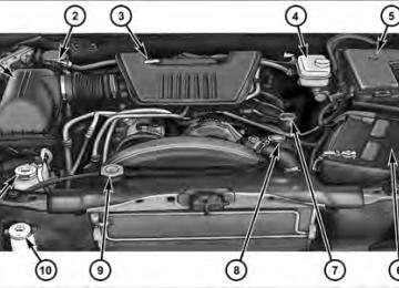
ENGINE BLOCK HEATER — IF EQUIPPED The engine block heater warms the engine, and permits quicker starts in cold weather. Connect the cord to a standard 110-115 Volt AC electrical outlet with a grounded, three-wire extension cord. The engine block heater cord is located at the right front of the engine compartment for all engine applications. The engine block heater must be plugged in at least one hour to have an adequate warming effect on the engine.
254 STARTING AND OPERATING
WARNING!
Remember to disconnect the engine block heater cord before driving. Damage to the 110-115 Volt electrical cord could cause electrocution.
AUTOMATIC TRANSMISSION
CAUTION! (Continued)
• Do not shift from REVERSE, PARK, or NEUTRAL into any forward gear when the engine is above idle speed. • Before shifting into any gear, make sure your foot
is firmly on the brake pedal.
CAUTION!
WARNING!
Damage to the transmission may occur if the follow- ing precautions are not observed: • Shift into PARK only after the vehicle has come to • Shift into or out of REVERSE only after the vehicle has come to a complete stop and the engine is at idle speed.
a complete stop.
(Continued)
It is dangerous to move the shift lever out of PARK or NEUTRAL if the engine speed is higher than idle speed. If your foot is not firmly on the brake pedal, the vehicle could accelerate quickly forward or in reverse. You could lose control of the vehicle and hit someone or something. Only shift into gear when the engine is idling normally and when your right foot is firmly on the brake pedal.
Key Ignition Park Interlock This vehicle is equipped with a Key Ignition Park Inter- lock which requires the shift lever to be placed in PARK prior to rotating the key to the LOCK position. The key can only be removed from the ignition when the ignition is in the LOCK position and once removed the shift lever is locked in PARK. Brake/Transmission Interlock System This vehicle is equipped with a Brake Transmission Shift Interlock System (BTSI) that holds the shift lever in the PARK position when the ignition switch is in the LOCK position. To move the shift lever out of the PARK position, the ignition switch must be turned to any other switch position (ACC, ON, or START) (engine running or not) and the brake pedal must be pressed. Automatic Transmission The electronic PRNDL on the instrument cluster indicates the transmission gear selected. The shift lever is mounted
STARTING AND OPERATING 255
on the right side of the steering column. To drive, move the shift lever from PARK or NEUTRAL to the desired drive position. Pull the shift lever toward you when shifting into REVERSE, SECOND, FIRST or PARK, or when shifting out of PARK. Gear Ranges DO NOT race the engine when shifting from PARK or NEUTRAL position into another gear range. PARK This range supplements the parking brake by locking the transmission. The engine can be started in this range. Never use PARK while the vehicle is in motion. Apply the parking brake when leaving the vehicle in this range. Always apply the parking brake first, then place the shift lever into the PARK position.256 STARTING AND OPERATING
WARNING!
• Never use the PARK position as a substitute for the parking brake. Always apply the parking brake fully when parked to guard against vehicle movement and possible injury or damage. • It is dangerous to move the shift lever out of PARK or NEUTRAL if the engine speed is higher than idle speed. If your foot is not firmly on the brake pedal, the vehicle could accelerate quickly forward or in reverse. You could lose control of the vehicle and hit someone or something. Only shift into gear when the engine is idling normally and when your right foot is firmly on the brake pedal.
(Continued)
WARNING! (Continued)
• Unintended movement of a vehicle could injure those in and near the vehicle. As with all vehicles, you should never exit a vehicle while the engine is running. Before exiting a vehicle, you should always shift the transmission into PARK, remove the key from the ignition, and apply the parking brake. Once the key is removed from the ignition, the shift lever is locked in the PARK position, securing the vehicle against unwanted movement. Furthermore, you should never leave unattended children inside a vehicle.
REVERSE This range is for moving the vehicle backward. Use only after the vehicle has come to a complete stop.
NEUTRAL This range is used when vehicle is standing for pro- longed periods with engine running. Engine may be started in this range. Set the parking brake and shift the transmission into PARK if you must leave the vehicle. DRIVE This range is for most city and highway driving. 2 (Second) This range is for driving slowly in heavy city traffic or on mountain roads where more precise speed control is desirable, use second gear. Use it also when climbing long grades, and for engine braking when descending moderately steep grades. To prevent excessive engine speed, do not exceed 45 mph (72 km/h) in this range. 1 (First) This range is for driving up very steep hills and for engine braking at low speeds, 25 mph (40 km/h) or less,
STARTING AND OPERATING 257
when going down hill, use first gear. To prevent excessive engine speed do not exceed 25 mph (40 km/h) in this range. Overdrive Operation The Overdrive automatic transmission contains an electronically-controlled fourth and fifth (if equipped) gear (Overdrive). The transmission will automatically shift from Drive to Overdrive, if the following conditions are present: • the shift lever is in DRIVE; • the engine coolant has reached normal operating tem- • vehicle speed is above approximately 30 mph • the TOW/HAUL switch has not been activated;(48 km/h);
perature;
258 STARTING AND OPERATING
• transmission temperature.
has
reached
normal
operating
NOTE: • If the vehicle is started in extremely cold temperatures, the transmission may not shift into Overdrive and will automatically select the most desirable gear for opera- tion at this temperature. Normal operation will re- sume when the transmission fluid temperature has risen to a suitable level. Refer to “Torque Converter Clutch” in this section. • If the transmission temperature gets extremely hot, the transmission will automatically select the most desir- able gear for operation at this temperature. If the transmission temperature becomes hot enough, the “Transmission Temperature Warning Light” may illu- minate and the transmission may downshift out of
Overdrive until the transmission cools down. After cool down, the transmission will resume normal operation.
from Overdrive to The transmission will downshift DRIVE if the accelerator pedal is fully pressed at vehicle speeds above approximately 35 mph (56 km/h). When to Use TOW/HAUL Mode When driving in hilly areas, towing a trailer, carrying a heavy load, etc., and frequent transmission shifting oc- curs, press the TOW/HAUL switch. This will improve performance and reduce the potential for transmission overheating or failure due to excessive shifting. When operating in TOW/HAUL mode, top gear is disabled and some shift patterns are modified. On vehicles with five- speed transmissions, shifts into Overdrive (fourth gear) are allowed during steady cruise (for improved fuel
economy), and automatic closed-throttle downshifts to third gear (for improved braking) will occur during steady braking.
TOW/HAUL Switch
The “TOW/HAUL Indicator Light” will illuminate in the instrument cluster to indicate when the switch has been activated. Pressing the switch a second time restores
STARTING AND OPERATING 259
normal operation. If the TOW/HAUL mode is desired, the switch must be pressed each time the engine is started. Torque Converter Clutch A feature designed to improve fuel economy is included in all automatic transmissions. A clutch, within the torque converter, engages automatically at a calibrated speed at light throttle. It engages at higher speeds under heavier acceleration. This may result in a slightly differ- ent feeling or response during normal operation in high gear. When the vehicle speed drops below a calibrated speed, or during acceleration, the clutch automatically and smoothly disengages. The feature is operational in Overdrive and in Drive. NOTE: • The torque converter clutch will not engage until the transmission fluid and engine coolant are warm (usu- ally after 1-3 miles [1.6 - 4.8 km] of driving). BecauseFOUR-WHEEL DRIVE OPERATION — IF EQUIPPED
Transfer Case Operating Information/Precautions The electronic-shift transfer case is operated by the transfer case switch, which is located on the instrument panel.
260 STARTING AND OPERATING
the engine speed is higher when the torque converter clutch is not engaged, it may seem as if the transmis- sion is not shifting into Overdrive when cold. This is normal. Pressing the TOW/HAUL switch, when the transmission is sufficiently warm, will demonstrate that the transmission is able to shift into, and out of Overdrive. • If the vehicle has not been driven in several days, the first few seconds of operation after shifting the trans- mission into gear may seem sluggish. This is due to the fluid partially draining from the torque converter into the transmission. This condition is normal and will not cause damage to the transmission. The torque con- verter will refill within five seconds of shifting from PARK into any other gear position.
Transfer Case Switch
The transfer case provides four mode positions: • Two-wheel drive high range (2WD) • Four-wheel drive lock range (4WD LOCK) • Four-wheel drive low range (4WD LOW) • Neutral (N) The transfer case is designed to be driven in the two- wheel drive position (2WD) for normal street and high- way conditions on dry hard-surfaced roads. When additional traction is required, the transfer case 4WD LOCK and 4WD LOW positions can be used to lock the front and rear driveshafts together and force the front and rear wheels to rotate at the same speed. This is accomplished by turning the transfer case switch to the desired position - Refer to “Shifting Procedure” for further information. The 4WD LOCK and 4WD LOW positions are designed for loose or slippery road surfaces
STARTING AND OPERATING 261
only. Driving in the 4WD LOCK and 4WD LOW posi- tions on dry hard-surfaced roads may cause increased tire wear and damage to the driveline components. NOTE: The transfer case NEUTRAL position is selected by pressing the recessed button located on the lower left-hand corner of the transfer case switch. The transfer case NEUTRAL position is to be used for recreational towing only. Refer to “Recreational Towing” in “Starting and Operating” for further information. Transfer Case Position Indicator Lights The Transfer Case Position Indicator Lights (4WD and 4LOW) are located on the instrument cluster. If there is no indicator light on or flashing, the transfer case is in two-wheel drive (2WD). If the indicator light is on, the desired position (4WD LOCK and 4WD LOW) has been obtained.262 STARTING AND OPERATING If one or more shift requirements are not met: 1. An indicator light will flash. 2. The transfer case will not shift. NOTE: Before retrying a selection, make certain that all the necessary requirements for selecting a new transfer case position have been met. To retry the selection, turn the transfer case switch back to the current position, wait five seconds, and retry selection. To find the shift require- ments, refer to the ⬙Shifting Procedure⬙ for further information. The “SVC 4WD Warning Light” monitors the electronic shift four-wheel drive system. If this light remains on after engine start-up or illuminates during driving, it means that the four-wheel drive system is not function- ing properly and that service is required.
WARNING!
Always engage the parking brake when powering down the vehicle if the “SVC 4WD Warning Light” is illuminated. Not engaging the parking brake may allow the vehicle to roll, which may cause personal injury.
NOTE: Do not attempt to make a shift while only the front or rear wheels are spinning. The transfer case is not equipped with a synchronizer and therefore the front and rear driveshaft speeds must be equal for the shift to take place. Shifting while only the front or rear wheels are spinning can cause damage to the transfer case. When operating your vehicle in 4WD LOW, the engine speed is approximately three times that of the 2WD or 4WD LOCK positions at a given road speed. Take care not to overspeed the engine and do not exceed 25 mph (40 km/h).
Proper operation of four-wheel drive vehicles depends on tires of equal size, type and circumference on each wheel. Any difference in tire size can cause damage to the transfer case. Because four-wheel drive provides improved traction, there is a tendency to exceed safe turning and stopping speeds. Do not go faster than road conditions permit.
WARNING!
You or others could be injured if you leave the vehicle unattended with the transfer case in the NEUTRAL position without first fully engaging the parking brake. The transfer case NEUTRAL position disengages both the front and rear driveshafts from the powertrain and will allow the vehicle to move regardless of the transmission position. The parking brake should always be applied when the driver is not in the vehicle.
STARTING AND OPERATING 263
For additional information on the appropriate use of each transfer case mode position, refer to the following infor- mation: 2WD Rear-Wheel Drive High — This range is used for normal street and highway driving on dry, hard-surfaced roads. 4WD LOCK Four-Wheel Drive Lock — This range locks the front and rear driveshafts together forcing the front and rear wheels to rotate at the same speed. This range provides additional traction for loose or slippery road surfaces only. 4WD LOW Four-Wheel Drive Low — This range provides low speed four-wheel drive. It locks the front and rear driveshafts together, forcing the front and rear wheels to rotate at the same speed. This range provides additional traction and264 STARTING AND OPERATING maximum pulling power for loose or slippery road surfaces only. Do not exceed 25 mph (40 km/h). Neutral — This range disengages both the front and rear driveshafts from the powertrain, and is used for flat towing behind another vehicle. Refer to “Recreational Towing” in “Starting and Operating” for further information. Shifting Procedure
If any of the requirements to select a new NOTE: transfer case position have not been met, the transfer case will not shift, the indicator light for the previous position will remain ON, and the newly-selected position indica- tor light will continue to flash until all the requirements for the selected position have been met. To retry a shift: return the transfer case switch back to the original position, make certain all shift requirements have been met, wait five seconds, and try the shift again.
2WD-to-4WD LOCK or 4WD LOCK-to-2WD Turn the transfer case switch to the desired position. Shifts between 2WD and 4WD LOCK can be done with the vehicle stopped, or in motion. With the vehicle in motion, the transfer case will engage/disengage faster if you momentarily release the accelerator pedal after turn- ing the transfer case switch. If the vehicle is stopped, the ignition key must be in the ON position with the engine either running or OFF. This shift cannot be completed if the key is in the ACC position. NOTE: On vehicles equipped with Anti-Lock Brake Systems, the four-wheel drive system will not allow shifts between 2WD/ 4WD LOCK if the rear wheels are spinning (no traction). In this situation, the selected position indicator light will flash and the original posi- tion indicator light will remain ON. At this time, reduce speed and stop spinning the wheels to complete the shift. There may be a delay up to 10 seconds for the shift to complete after the wheels have stopped spinning.
4WD LOCK-to-4WD LOW or 4WD LOW-to-4WD LOCK NOTE: When shifting into or out of 4WD LOW, some gear noise may be heard. This noise is normal and is not detrimental to the vehicle or occupants. Shifting can be performed with the vehicle rolling 2 to 3 mph (3 to 5 km/h), or completely stopped. USE EITHER OF THE FOLLOWING PROCEDURES: Preferred Procedure 1. With the engine running, slow the vehicle to 2 to 3 mph (3 to 5 km/h). 2. Shift the transmission into NEUTRAL. 3. While still rolling, turn the transfer case switch to the desired position. 4. After the desired position indicator light is ON (not flashing), shift the transmission back into gear.
STARTING AND OPERATING 265
Alternate Procedure 1. Bring the vehicle to complete stop. 2. With the key ON and the engine either OFF or running, shift the transmission into NEUTRAL. 3. Turn the transfer case switch to the desired position. 4. After the desired position indicator light is ON (not flashing), shift the transmission back into gear. NOTE: • If Steps 1 or 2 of the Preferred or Alternate Procedure are not satisfied prior to attempting the shift, or if they no longer are being met while the shift attempt is in process, then the indicator light will flash and the current transfer case position will be maintained. To retry the selection, turn the transfer case switch back to the current position, wait five seconds, and retry shift.
266 STARTING AND OPERATING
• The ignition key must be ON for a shift to take place and for the position indicator lights to be operable. If the key is not ON, then the shift will not take place and no position indicator lights will be on or flashing.
LIMITED-SLIP REAR AXLE DIFFERENTIAL — IF EQUIPPED The limited-slip differential provides additional traction on snow, ice, mud, sand and gravel. It improves traction when there is a difference between the characteristics of the surface under the right and left rear wheels. During normal driving and cornering, the limited-slip unit is similar to a conventional differential. But on a slippery surface, the differential delivers more of the driving effort to the wheel having the better traction.
WARNING!
On vehicles equipped with a limited-slip differen- tial, never run the engine with one rear wheel off the ground. The vehicle may drive through the rear wheel remaining on the ground and cause you to lose control of the vehicle.
Care should be taken to avoid sudden accelerations when both rear wheels are on a slippery surface. This could cause both rear wheels to spin, and allow the vehicle to slide sideways on the crowned surface of a road or in a turn.
DRIVING ON SLIPPERY SURFACES
Acceleration Rapid acceleration on snow covered, wet, or other slip- pery surfaces may cause the rear wheels to pull errati- cally to the right or left. This phenomenon occurs when there is a difference in the surface traction under the rear (driving) wheels.
WARNING!
Rapid acceleration on slippery surfaces is dangerous. Unequal traction can cause sudden pulling of the rear wheels. You could lose control of the vehicle and possibly have a collision. Accelerate slowly and carefully whenever there is likely to be poor traction (ice, snow, wet mud, loose sand, etc.).
STARTING AND OPERATING 267
Traction When driving on wet or slushy roads, it is possible for a wedge of water to build up between the tire and road surface. This is known as hydroplaning and may cause partial or complete loss of vehicle control and stopping ability. To reduce this possibility, the following precau- tions should be observed: 1. Slow down during rainstorms or when the roads are slushy. 2. Slow down if the road has standing water or puddles. 3. Replace tires when tread wear indicators first become visible. 4. Keep tires properly inflated. 5. Maintain sufficient distance between your vehicle and the vehicle in front of you to avoid a collision in a sudden stop.
268 STARTING AND OPERATING DRIVING THROUGH WATER Driving through water more than a few inches/ centimeters deep will require extra caution to ensure safety and prevent damage to your vehicle. Flowing/Rising Water
WARNING!
Do not drive on or across a road or path where water is flowing and/or rising (as in storm run-off). Flow- ing water can wear away the road or path’s surface and cause your vehicle to sink into deeper water. Furthermore, flowing and/or rising water can carry your vehicle away swiftly. Failure to follow this warning may result in injuries that are serious or fatal to you, your passengers, and others around you.
Shallow Standing Water Although your vehicle is capable of driving through shallow standing water, consider the following Caution and Warning before doing so.
CAUTION!
• Always check the depth of the standing water before driving through it. Never drive through standing water that is deeper than the bottom of the tire rims mounted on the vehicle. • Determine the condition of the road or the path that is under water and if there are any obstacles in the way before driving through the standing wa- ter. • Do not exceed 5 mph (8 km/h) when driving through standing water. This will minimize wave effects.
(Continued)
CAUTION! (Continued)
• Driving through standing water may cause dam- age to your vehicle’s drivetrain components. Al- ways inspect your vehicle’s fluids (i.e., engine oil, transmission, axle, etc.) for signs of contamination (i.e., fluid that is milky or foamy in appearance) after driving through standing water. Do not con- tinue to operate the vehicle if any fluid appears contaminated, as this may result in further dam- age. Such damage is not covered by the New Vehicle Limited Warranty. • Getting water inside your vehicle’s engine can cause it to lock up and stall out, and cause serious internal damage to the engine. Such damage is not covered by the New Vehicle Limited Warranty.
STARTING AND OPERATING 269
WARNING!
• Driving through standing water limits your vehi- cle’s traction capabilities. Do not exceed 5 mph (8 km/h) when driving through standing water. • Driving through standing water limits your vehi- cle’s braking capabilities, which increases stop- ping distances. Therefore, after driving through standing water, drive slowly and lightly press on the brake pedal several times to dry the brakes. • Getting water inside your vehicle’s engine can cause it to lock up and stall out, and leave you stranded. • Failure to follow these warnings may result in injuries that are serious or fatal to you, your passengers, and others around you.
270 STARTING AND OPERATING OFF-ROAD DRIVING TIPS Care should be taken when attempting to climb steep hills or driving diagonally across a hill or slope. If natural obstacles force you to travel diagonally up or down a hill, choose a mild angle and keep as little side tilt as possible. Keep the vehicle moving and make turns slowly and cautiously. If you must back down a hill, back straight down using REVERSE gear. Never back down in NEUTRAL or diago- nally across the hill. When driving over sand, mud, and other soft terrain, shift to low gear and drive steadily. Apply the accelerator slowly to avoid spinning the wheels. Do not reduce the tire pressures for this type of driving. After Driving Off-Road Off-road operation puts more stress on your vehicle than does most on-road driving. After going off-road, it is
required.
always a good idea to check for damage. That way you can get any problems taken care of right away and have your vehicle ready when you need it. • Completely inspect the underbody of your vehicle. Check tires, body structure, steering, suspension, and exhaust system for damage. • Inspect the radiator for mud and debris and clean as • Check threaded fasteners for looseness, particularly on the chassis, drivetrain components, steering, and sus- pension. Retighten them, if required, and torque to the values specified in the Service Manual. • Check for accumulations of plants or brush. These things could be a fire hazard. They might hide damage to fuel lines, brake hoses, axle pinion seals, and propeller shafts.
• After extended operation in mud, sand, water, or similar dirty conditions, have the radiator, fan, brake rotors, wheels, brake linings, and axle yokes inspected and cleaned as soon as possible.
WARNING!
Abrasive material in any part of the brakes may cause excessive wear or unpredictable braking. You might not have full braking power when you need it to prevent a collision. If you have been operating your vehicle in dirty conditions, get your brakes checked and cleaned as necessary. • If you experience unusual vibration after driving in mud, slush or similar conditions, check the wheels for impacted material. Impacted material can cause a wheel imbalance and freeing the wheels of it will correct the situation.
STARTING AND OPERATING 271
POWER STEERING The standard power steering system will give you good vehicle response and increased ease of maneuverability in tight spaces. The system will provide mechanical steering capability if power assist is lost. If for some reason the power assist is interrupted, it will still be possible to steer your vehicle. Under these condi- tions, you will observe a substantial increase in steering effort, especially at very low vehicle speeds and during parking maneuvers. NOTE: • Increased noise levels at the end of the steering wheel travel are considered normal and do not indicate that there is a problem with the power steering system. • Upon initial start-up in cold weather, the power steer- ing pump may make noise for a short amount of time. This is due to the cold, thick fluid in the steering
272 STARTING AND OPERATING
system. This noise should be considered normal, and it does not in any way damage the steering system.
WARNING!
Continued operation with reduced power steering assist could pose a safety risk to yourself and others. Service should be obtained as soon as possible.
CAUTION!
Prolonged operation of the steering system at the end of the steering wheel travel will increase the steering fluid temperature and it should be avoided when possible. Damage to the power steering pump may occur.
Power Steering Fluid Check Checking the power steering fluid level at a defined service interval is not required. The fluid should only be
checked if a leak is suspected, abnormal noises are apparent, and/or the system is not functioning as antici- pated. Coordinate inspection efforts through an autho- rized dealer.
CAUTION!
Do not use chemical flushes in your power steering system as the chemicals can damage your power steering components. Such damage is not covered by the New Vehicle Limited Warranty.
WARNING!
Fluid level should be checked on a level surface and with the engine off to prevent injury from moving parts and to ensure accurate fluid level reading. Do not overfill. Use only manufacturer’s recommended power steering fluid.
If necessary, add fluid to restore to the proper indicated level. With a clean cloth, wipe any spilled fluid from all surfaces. Refer to “Fluids, Lubricants, and Genuine Parts” in “Maintaining Your Vehicle” for further information.
PARKING BRAKE Before leaving the vehicle, make sure that the parking brake is fully applied and place the shift lever in the PARK position. The foot operated parking brake is located below the lower left corner of the instrument panel. To apply the park brake, firmly push the park brake pedal fully. To release the parking brake, pull the parking brake release handle.
STARTING AND OPERATING 273
Parking Brake
When the parking brake is applied with the ignition switch ON, the “Brake Warning Light” in the instrument cluster will illuminate. NOTE: The “Brake Warning Light” only shows that the parking brake is applied. It does not show the degree of brake application.
274 STARTING AND OPERATING When parking on a hill, it is important to turn the front wheels toward the curb on a downhill grade and away from the curb on an uphill grade. Apply the parking brake before placing the shift lever in PARK, otherwise the load on the transmission locking mechanism may make it difficult to move the shift lever out of PARK. The parking brake should always be applied whenever the driver is not in the vehicle.
WARNING!
• Never use the PARK position of the transmission as a substitute for the parking brake. Always apply the parking brake fully when parked to guard against vehicle movement and possible in- jury or damage.
(Continued)
WARNING! (Continued)
• Never leave children alone in a vehicle. Leaving unattended children in a vehicle is dangerous for a number of reasons. A child or others could be seriously or fatally injured. • Do not leave the key in the ignition. A child could operate power windows, other controls, or move the vehicle. • Be sure the parking brake is fully disengaged before driving; failure to do so can lead to brake failure and a collision. • Always fully apply the parking brake when leav- ing your vehicle, or it may roll and cause damage or injury. Also be certain to leave the transmission in PARK. Failure to do so may allow the vehicle to roll and cause damage or injury.
CAUTION!
If the “Brake Warning Light” remains on with the parking brake released, a brake system malfunction is indicated. Have the brake system serviced by an authorized dealer immediately.
BRAKE SYSTEM In the event power assist is lost for any reason (for example, repeated brake applications with the engine off), the brakes will still function. The effort required to brake the vehicle will be significantly more than that required with the power system operating. If either the front or rear hydraulic system loses normal capability, the remaining system will still function with some loss of braking effectiveness. This will be evident by increased pedal travel during application, greater pedal
STARTING AND OPERATING 275
force required to slow or stop, and activation of the “Brake Warning Light” and the “ABS Warning Light” during brake use. Four-Wheel Anti-Lock Brake System (ABS) The Four-Wheel ABS is designed to aid the driver in maintaining vehicle control under adverse braking con- ditions. The system operates with a separate computer to modulate hydraulic pressure, to prevent wheel lock-up and help avoid skidding on slippery surfaces. The system’s pump motor runs during an ABS stop to provide regulated hydraulic pressure. The pump motor makes a low humming noise during operation, which is normal. The ABS includes an amber “ABS Warning Light.” When the light is illuminated, the ABS is not functioning. The system reverts to standard non-anti-lock brakes. Turning the ignition OFF and ON again may reset the ABS if the fault detected was only momentary.276 STARTING AND OPERATING
WARNING!
Pumping of the Anti-Lock Brakes will diminish their effectiveness and may lead to a collision. Pumping makes the stopping distance longer. Just press firmly on your brake pedal when you need to slow down or stop.
WARNING!
• The Anti-Lock Brake System (ABS) cannot prevent the natural laws of physics from acting on the vehicle, nor can it increase braking or steering efficiency beyond that afforded by the condition of the vehicle brakes and tires or the traction afforded.
(Continued)
WARNING! (Continued) • The ABS cannot prevent collisions,
including those resulting from excessive speed in turns, following another vehicle too closely, or hydro- planing. • The capabilities of an ABS-equipped vehicle must never be exploited in a reckless or dangerous manner, which could jeopardize the user’s safety or the safety of others.
When you are in a severe braking condition involving use of the ABS, you will experience some pedal drop as the vehicle comes to a stop. This is the result of the system reverting to the base brake system. Engagement of the ABS may be accompanied by a pulsing sensation. You may also hear a clicking noise. These occurrences are normal, and indicate that the system is functioning properly.
TIRE SAFETY INFORMATION
Tire Markings
1 — U.S. DOT Safety Stan- dards Code (TIN) 2 — Size Designation 3 — Service Description
4 — Maximum Load
5 — Maximum Pressure 6 — Treadwear, Traction and Temperature Grades
STARTING AND OPERATING 277
NOTE: • P (Passenger) - Metric tire sizing is based on U.S. design standards. P-Metric tires have the letter “P” molded into the sidewall preceding the size designa- tion. Example: P215/65R15 95H. • European-Metric tire sizing is based on European design standards. Tires designed to this standard have the tire size molded into the sidewall beginning with the section width. The letter ⬙P⬙ is absent from this tire size designation. Example: 215/65R15 96H. • LT (Light Truck) - Metric tire sizing is based on U.S. design standards. The size designation for LT-Metric tires is the same as for P-Metric tires except for the letters “LT” that are molded into the sidewall preced- ing the size designation. Example: LT235/85R16. • Temporary spare tires are high-pressure compact spares designed for temporary emergency use only.
278 STARTING AND OPERATING
Tires designed to this standard have the letter “T” molded into the sidewall preceding the size designa- tion. Example: T145/80D18 103M.
• High flotation tire sizing is based on U.S. design standards and it begins with the tire diameter molded into the sidewall. Example: 31x10.5 R15 LT.
Tire Sizing Chart
Size Designation:
EXAMPLE:
P = Passenger car tire size based on U.S. design standards ⴖ....blank....ⴖ = Passenger car tire based on European design standards LT = Light truck tire based on U.S. design standards T = Temporary spare tire 31 = Overall diameter in inches (in) 215 = Section width in millimeters (mm) 65 = Aspect ratio in percent (%)
— Ratio of section height to section width of tire
10.5 = Section width in inches (in) R = Construction code
— ⬙R⬙ means radial construction —⬙D⬙ means diagonal or bias construction
STARTING AND OPERATING 279
15 = Rim diameter in inches (in)
Service Description:
95 = Load Index
EXAMPLE:
— A numerical code associated with the maximum load a tire can carry
H = Speed Symbol
— A symbol indicating the range of speeds at which a tire can carry a load corresponding to its load index under certain operating conditions — The maximum speed corresponding to the speed symbol should only be achieved under specified operating conditions (i.e., tire pressure, vehicle loading, road conditions, and posted speed limits)
Load Identification:
ⴖ....blank....ⴖ = Absence of any text on the sidewall of the tire indicates a Standard Load (SL) tire Extra Load (XL) = Extra load (or reinforced) tire Light Load = Light load tire C, D, E = Load range associated with the maximum load a tire can carry at a specified pressure
Maximum Load — Maximum load indicates the maximum load this tire is designed to carry Maximum Pressure — Maximum pressure indicates the maximum permissible cold tire inflation pressure for this tire
280 STARTING AND OPERATING Tire Identification Number (TIN) The TIN may be found on one or both sides of the tire, however, the date code may only be on one side. Tires with white sidewalls will have the full TIN, including the date code, located on the white sidewall side of the tire.
Look for the TIN on the outboard side of black sidewall tires as mounted on the vehicle. If the TIN is not found on the outboard side, then you will find it on the inboard side of the tire.
EXAMPLE:
DOT MA L9 ABCD 0301
DOT = Department of Transportation
— This symbol certifies that the tire is in compliance with the U.S. Department of Transportation tire safety standards and is approved for highway use
MA = Code representing the tire manufacturing location (two digits) L9 = Code representing the tire size (two digits) ABCD = Code used by the tire manufacturer (one to four digits) 03 = Number representing the week in which the tire was manufactured (two digits)
—03 means the 3rd week.
01 = Number representing the year in which the tire was manufactured (two digits)
—01 means the year 2001
— Prior to July 2000, tire manufacturers were only required to have one number to represent the year in which the tire was manufactured. Example: 031 could represent the 3rd week of 1981 or 1991Tire Terminology and Definitions
B-Pillar
Term
Cold Tire Pressure
Maximum Inflation Pressure
Recommended Inflation Pressure
Tire Placard
STARTING AND OPERATING 281
Definition
The vehicle B-Pillar is a structural member of the body located between the front and rear door (of a four-door vehicle) running from the sill to the roof. Cold tire inflation pressure is defined as the tire pressure after the vehicle has not been driven for at least 3 hours, or driven less