- 2010 Dodge Dakota Owners Manuals
- Dodge Dakota Owners Manuals
- 2008 Dodge Dakota Owners Manuals
- Dodge Dakota Owners Manuals
- 2006 Dodge Dakota Owners Manuals
- Dodge Dakota Owners Manuals
- 2009 Dodge Dakota Owners Manuals
- Dodge Dakota Owners Manuals
- 2004 Dodge Dakota Owners Manuals
- Dodge Dakota Owners Manuals
- 2011 Dodge Dakota Owners Manuals
- Dodge Dakota Owners Manuals
- 2005 Dodge Dakota Owners Manuals
- Dodge Dakota Owners Manuals
- 2007 Dodge Dakota Owners Manuals
- Dodge Dakota Owners Manuals
- Download PDF Manual
-
UNDERSTANDING THE FEATURES OF YOUR VEHICLE 145
without erasing the memory. Pushing the ON/OFF but- ton to the OFF position or turning off the ignition erases the memory.WARNING!
Leaving the Electronic Speed Control ON when not in use is dangerous. You could accidentally set the Electronic Speed Control to cause it to go faster than you want. You could lose control and have an acci- dent. Always leave the system OFF when you are not using it.
To Resume Speed To resume a previously set speed, push and release the RESUME button. Resume can be used at any speed above 20 mph (32 km/h).
146 UNDERSTANDING THE FEATURES OF YOUR VEHICLE To Vary The Speed Setting When the Electronic Speed Control System is ON, the speed can be increased by pressing and holding the RESUME/ACCEL button. When the button is released, a new set speed will be established. Tapping the ACCEL button once will result in a 1 mph (2 km/h) increase in set speed. Each subsequent tap of the button results in an increase of 1 mph (2 km/h). Tapping the DECEL button once will result in a speed decrease of 1 mph (2 km/h). Each time the button is tapped, speed will decrease. For example, tapping the button three times will decrease the speed by 3 mph (4.8 km/h). Tapping the DECEL button once will result in a 1 mph (2 km/h) decrease in set speed. Each subsequent tap of the button results in a decrease of 1 mph (2 km/h).
To Accelerate For Passing Press the accelerator as you would normally. When the pedal is released, the vehicle will return to the set speed. NOTE: When driving uphill, at elevations above 2,000 ft (610 m), or when the vehicle is heavily loaded (especially when towing) the vehicle may slow below the SET speed. If the vehicle speed drops below 25 mph (40 km/h), the Electronic Speed Control will automatically disengage. If this happens, you can push down on the accelerator pedal to maintain the desired speed. Vehicles equipped with an automatic transmission may exhibit several downshifts under the above conditions. To reduce the frequency of the downshifts and to im- prove vehicle performance, it is advisable to lock out OVERDRIVE by pressing the TOW/HAUL button lo- cated at the end of the shift lever.
WARNING!
Electronic Speed Control can be dangerous where the system cannot maintain a constant speed. Your ve- hicle could go too fast for the conditions, and you could lose control and have an accident. Do not use Electronic Speed Control in heavy traffic or on roads that are winding, icy, snow-covered or slippery.
OVERHEAD CONSOLE The overhead console has the following features:
UNDERSTANDING THE FEATURES OF YOUR VEHICLE 147
Overhead Console
• Courtesy Lights • Garage Door Opener — If Equipped • Compass/Temperature Mini-Trip Computer — If
Equipped
COMPASS/TEMPERATURE MINI-TRIP COMPUTER This feature allows you to choose between a compass/ temperature display and one of four trip conditions being monitored. US/M Button Use the US/M button to change the display from U.S. to metric measurement units.
148 UNDERSTANDING THE FEATURES OF YOUR VEHICLE Courtesy/Reading Lights Near the front of the console are two courtesy/reading lights. Both lights illuminate as courtesy lights when a door is opened, when the dimmer control is rotated to the courtesy light position (fully upward position), or when the UNLOCK button is pressed on the Remote Keyless Entry (RKE) transmitter, if equipped. These lights are also operated individually as reading lights by pressing the recessed area of the corresponding lens. NOTE: The courtesy/reading lights will remain on until the switch is pressed a second time, so be sure they have been turned off before leaving the vehicle. If the interior lights are left on after the vehicle is turned OFF, they will extinguish after approximately 10 minutes.
US/M Button
RESET Button Use the RESET button to reset the following displays: • Average Fuel Economy • Trip Odometer • Elapsed time.
UNDERSTANDING THE FEATURES OF YOUR VEHICLE 149
STEP Button Use the STEP button to choose, or cycle through, the four trip conditions.
RESET Button
STEP Button
Average Fuel Economy (AVG ECO) Displays the average fuel economy since the last reset. Average fuel economy is a running average of the
150 UNDERSTANDING THE FEATURES OF YOUR VEHICLE amount of fuel used and the distance the vehicle has traveled. When the fuel economy is reset, the display will momentarily blank, the history will be erased, and the AVERAGE WILL CONTINUE FROM WHERE IT WAS BEFORE THE RESET. The reset value is based on a minimal amount of fuel used and the distance traveled from the previous drive cycle. The display may take several miles/kilometers for this value to change, de- pending upon driving habits. Distance To Empty (DTE) Shows the estimated distance that can be traveled with the fuel remaining in the tank. The estimated distance is determined by a weighted average of the instantaneous and average fuel economy, according to the current fuel tank level. NOTE: The DTE is not resettable. When Distance To Empty = LOW FUEL, the fuel gauge pointer will initially be on the red “E” marker. At this
point (fuel gauge pointer on the red “E” marker), there is reserve fuel capacity, which corresponds to approxi- mately 8% of tank volume. This reserve capacity was put in place to prevent the likelihood of customers running out of fuel when operating at maximum load conditions in areas where there aren’t many gas stations. NOTE: The Distance To Empty will remain equal to zero until the vehicle runs out of fuel or is refueled. Trip Odometer (ODO) This display shows the distance traveled since the last reset. NOTE: 6000 miles (9656 km). Resetting of this screen will cause the trip odometer to change to zero. Then the trip odometer must be reset in order to update the trip odometer miles.
The maximum value
approximately
is
Elapsed Time (ET) This display shows the accumulated ignition ON time since the last reset. Resetting the Elapsed Time will cause the display to change to zero. C/T Button Use the C/T (Compass/Temperature) button to select a readout of the outside temperature and one of eight compass headings that indicate the direction in which the vehicle is facing.
UNDERSTANDING THE FEATURES OF YOUR VEHICLE 151
C/T Button
The system will display the last known outside tempera- ture when starting the vehicle and may need to be driven several minutes before the updated temperature is dis- played. Engine temperature can also affect the displayed temperature, therefore temperature readings are not up- dated when the vehicle is not moving.
152 UNDERSTANDING THE FEATURES OF YOUR VEHICLE Global Reset If the RESET button is pressed twice within two seconds while in any of the three resettable displays (AVG ECO, ODO, ET), the GLOBAL RESET will reset all three displays. Compass/Temperature Display
WARNING!
Even if the display still reads a few degrees above 32° F (0° C), the road surface may be icy, particularly in woods or on bridges. Drive carefully under such conditions to prevent an accident and possible per- sonal injury or property damage.
Automatic Compass Calibration This compass is self-calibrating which eliminates the need to manually set the compass. When the vehicle is new, the compass may appear erratic and the CAL symbol will be displayed. After completing one 360 degree turn with the vehicle traveling less than 5 mph (8 km/h) in an area free from large metal or metallic objects, the CAL symbol will turn off and the compass will function normally. NOTE: Magnetic materials should be kept away from the Overhead Console. This is where the compass sensor is located. Manual Compass Calibration
NOTE: To ensure proper compass calibration, make sure the compass variance is properly set before manu- ally calibrating the compass.
If the compass appears erratic and the CAL symbol does not appear, you must manually put the compass into the “Calibration” mode. To Put Into A Calibration Mode Turn the ignition ON and set the display to “Compass/ Temperature.” Press and hold the RESET button to change the display between VAR (compass variance) and CAL (compass calibration) modes. When the CAL sym- bol is displayed, complete one 360 degree turn in an area free from large metal objects or power lines. The CAL symbol will turn off and the compass will function normally. Compass Variance is the difference between magnetic North and geographic North. In some areas of the country, the difference between magnetic and geographic North is great enough to cause the compass to give false readings. If this occurs, the compass variance must be set according to the Compass Variance Map.
UNDERSTANDING THE FEATURES OF YOUR VEHICLE 153
Compass Variance Map
To set the variance: Turn the ignition ON and set the display to “Compass/Temperature.” Press and hold the RESET button approximately five seconds. The last vari- ance zone number will be displayed. Press the STEP button to select the new variance zone and press the RESET button to resume normal operation.
154 UNDERSTANDING THE FEATURES OF YOUR VEHICLE Outside Temperature Because the ambient temperature sensor is located under the hood, engine temperature can influence the displayed temperature; therefore, temperature readings are slowly updated when the vehicle speed is below 20 mph (30 km/h) or during stop-and-go driving.
GARAGE DOOR OPENER — IF EQUIPPED HomeLink威 replaces up to three remote controls (hand- held transmitters) that operate devices such as garage door openers, motorized gates, lighting or home security systems. The HomeLink威 unit operates off of your vehi- cle’s battery. The HomeLink威 buttons are located in the overhead console, and contain one, two or three dots/lines desig- nating the different HomeLink威 channels.
HomeLink Buttons
NOTE: HomeLink威 is disabled when the Vehicle Theft Alarm is active.
WARNING!
• Your motorized door or gate will open and close while you are training the Universal Transceiver. Do not train the transceiver if people, pets or other objects are in the path of the door or gate. Only use this transceiver with a garage door opener that has a “stop and reverse” feature as required by federal safety standards. This includes most garage door opener models manufactured after 1982. Do not use a garage door opener without these safety features. Call toll-free 1–800–355–3515 or, on the Internet at www.HomeLink.com for safety infor- mation or assistance. • Vehicle exhaust contains carbon monoxide, a dan- gerous gas. Do not run your vehicle in the garage while training the transceiver. Exhaust gas can cause serious injury or death.
UNDERSTANDING THE FEATURES OF YOUR VEHICLE 155
Programming HomeLink姞
Before You Begin The Compass Mini-Trip Computer (CMTC) illuminates the HomeLink威 symbol (a house with an arrow inside it) along with 1, 2 or 3 indicators under it, when a HomeLink威 button is pressed. Pay attention to the indicator(s), as they will flash at different rates, or remain solid during training. If you have not trained any of the HomeLink威 buttons, erase all channels before you begin training. To do this, press and hold the two outside buttons for 20 seconds. Release the buttons when the indicators start to flash. It is recommended that a new battery be placed in the handheld transmitter of the device being copied to HomeLink威 for more efficient training and accurate transmission of the radio-frequency signal.
156 UNDERSTANDING THE FEATURES OF YOUR VEHICLE Your vehicle should be parked outside of the garage while training. • Turn the ignition switch to the ON/RUN position. • Place the handheld transmitter 1 to 3 inches (3 to 8 cm) from the HomeLink威 buttons while keeping the HomeLink威 display in view. For optimal training, point the battery end of the handheld transmitter away from the HomeLink威. • Simultaneously, press and hold both the chosen HomeLink威button and the handheld transmitter but- ton until the indicator(s) change from a slow to a rapid flash rate. Then release both the HomeLink威 and handheld trans- mitter buttons.
It may take up to 30 seconds or longer in rare cases. The garage door may open and close while you train.
If the signal is too weak to train, replace the battery in the handheld transmitter. NOTE: Some gate operators and garage door openers may require you to replace Step 3 with procedures noted in the “Gate Operator/Canadian Programming” section. • Press and hold the just-trained HomeLink威 button. If the indicator(s) blink rapidly for two seconds and then remains constant, continue with the next section: “Pro- gramming A Rolling Code System”.
NOTE: After training a HomeLink威 channel, if the garage door does not operate with HomeLink威 and the garage door opener was manufactured after 1995, the garage door opener may have rolling code. If so, proceed to the heading, “Programming A Rolling Code System.” Programming A Rolling Code System At the garage door opener motor (in the garage), locate the “Learn” or “Training” button.
This can usually be found where the hanging antenna wire is attached to the garage door opener motor (it is NOT the button normally used to open and close the door).
1 — Garage Door Opener 2 — Training Button
UNDERSTANDING THE FEATURES OF YOUR VEHICLE 157
1. Firmly press and release the LEARN or TRAINING button. The name and color of the button may vary by manufacturer. NOTE: You have 30 seconds in which to initiate the next step after the LEARN button has been pressed. 2. Return to the vehicle and press the programmed HomeLink威 button twice (holding the button for two seconds each time). If the device is plugged in and activates, programming is complete. If the device does not activate, press the button a third time (for two seconds) to complete the training. If you are have any problems, or require assistance, please call toll-free 1–800–355–3515 or, on the Internet at www.HomeLink.com for information or assistance. To program the remaining two HomeLink威 buttons, repeat each step for each remaining button. DO NOT erase the channels.158 UNDERSTANDING THE FEATURES OF YOUR VEHICLE Gate Operator/Canadian Programming Canadian radio-frequency laws require transmitter sig- nals to “time-out” (or quit) after several seconds of transmission – which may not be long enough for HomeLink威 to pick up the signal during programming. Similar to this Canadian law, some U.S. gate operators are designed to “time-out” in the same manner. It may be helpful to unplug the device during the cycling process to prevent possible overheating of the garage door or gate motor. If you are having difficulties programming a garage door opener or a gate operator, replace “Programming HomeLink,” Step 3, with the following: 3. Continue to press and hold the HomeLink威 button, while you press and release (“cycle”), your handheld transmitter every two seconds until HomeLink威 has
successfully accepted the frequency signal. The indica- tor(s) will change from a slow flash to a rapid flash when trained. If you unplugged the device for training, plug it back in at this time. Then proceed with Step 4 under, “Programming HomeLink威,” earlier in this section. Using HomeLink姞 To operate, press the programmed HomeLink威 button. Activation will now occur for the trained device (i.e., garage door opener, gate operator, security system, entry door lock, home/office lighting, etc.,). The handheld transmitter of the device may also be used at any time. Reprogramming A Single HomeLink姞 Button To reprogram a channel that has been previously trained, follow these steps:
and release
1. Turn the ignition switch to the ON/RUN position. 2. Press and hold the desired HomeLink威 button for 20 seconds until the indicator(s) starts to flash. Do not release the button. 3. Without releasing the button, proceed with Program- ming HomeLink威, Step #2, and follow all remaining steps. Security It is advised to erase all channels before you sell or turn in your vehicle. To do this, press and hold the two outside buttons for 20 seconds until the indicators begin to flash. Note that all channels will be erased. Individual channels cannot be erased. The HomeLink威 Universal Transceiver is disabled when the Vehicle Theft Alarm is active.
UNDERSTANDING THE FEATURES OF YOUR VEHICLE 159
Troubleshooting Tips If you are having trouble programming HomeLink威, here are some of the most common solutions: • Replace the battery in the original transmitter. • Press the LEARN button on the garage door opener to • Did you unplug the device for training and remember
complete the training for Rolling Code.
to plug it back in?
If you have any problems, or require assistance, please call toll-free 1–800–355–3515 or, on the Internet at www.HomeLink.com, for information or assistance. General Information This device complies with FCC rules part 15 and Industry Canada RSS-210. Operation is subject to the following two conditions: 1. This device may not cause harmful interference.
160 UNDERSTANDING THE FEATURES OF YOUR VEHICLE 2. This device must accept any interference that may be received including interference that may cause undesired operation. NOTE: The transmitter has been tested and it complies with FCC and IC rules. Changes or modifications not expressly approved by the party responsible for compli- ance could void the user’s authority to operate the device. The term “IC” before the certification/registration num- ber only signifies that Industry Canada technical specifi- cations were met.
ELECTRICAL POWER OUTLETS This vehicle has two 12 Volt (13 Amp) auxiliary power outlets that can provide power for accessories designed for use with standard power outlet adapters. One power outlet is located in the instrument panel (below the temperature control setting knob) and one is located inside the full-size center console.
Instrument Panel Outlet
When the optional Cigar Lighter heating element is used, it heats when pushed in and pops out automatically when ready for use. To preserve the heating element, do not hold the lighter in the heating position. NOTE: To ensure proper operation a MOPAR威 knob and element must be used.
CAUTION!
• Do not exceed the maximum power of 160 Watts (13 Amps) at 12 Volts. If the 160 Watt (13 Amp) power rating is exceeded the fuse protecting the system will need to be replaced. • Power outlets are designed for accessory plugs only. Do not insert any other object in the power outlets as this will damage the outlet and blow the fuse. Improper use of the power outlet can cause damage not covered by your warranty.
UNDERSTANDING THE FEATURES OF YOUR VEHICLE 161
Power Outlet Fuse Locations
1 — #22 Fuse 20 A Yellow Cigar Lighter Front Console 2 — #28 Fuse 20 A Yellow Power Outlet Center Console
162 UNDERSTANDING THE FEATURES OF YOUR VEHICLE
WARNING!
To avoid serious injury or death: • Only devices designed for use in this type of outlet should be inserted into any 12 Volt outlet. • Do not touch with wet hands. • Close the lid when not in use and while driving • If this outlet is mishandled, it may cause an
the vehicle.
electric shock and failure.
CAUTION!
• Many accessories that can be plugged in, draw power from the vehicle’s battery, even when not in use (i.e., cellular phones, etc.). Eventually, if plugged in long enough, the vehicle’s battery will discharge sufficiently to degrade battery life and/or prevent the engine from starting. • Accessories that draw higher power (i.e., coolers, vacuum cleaners, lights, etc.), will discharge the battery even more quickly. Use these only inter- mittently and with greater caution. • After the use of high power draw accessories, or long periods of the vehicle not being started (with accessories still plugged in), the vehicle must be driven a sufficient length of time to allow the generator to recharge the vehicle’s battery.
CUPHOLDERS If your vehicle has bucket seats with a center console, there are three cupholders located on the console.
UNDERSTANDING THE FEATURES OF YOUR VEHICLE 163
A two-cavity cupholder is available on all Crew Cabs, with rear seats mounted on the floor.Front Cup Holders — Crew Cab
Rear Cup Holders — Crew Cab
164 UNDERSTANDING THE FEATURES OF YOUR VEHICLE REAR CRATE ’N GO姞 STORAGE — IF EQUIPPED The rear Crate ’n Go威 storage, located under the rear seat lower cushion, consists of two removable, collapsible storage crates.
To open the crates, lift upward on the crate handles and engage the crate end flaps. To remove the crate, press on the release lever, located on the ends of the base, and lift up on the crate. To install the crate into the base, insert the crate into the inboard slot and push down on the outboard side of the crate, then snap into place.
Open Crate
1 — Crate Handles 2 — Crate End Flaps 3 — Release Lever
UNDERSTANDING THE FEATURES OF YOUR VEHICLE 165
WARNING!
Do not sit or stand on this crate. It may collapse causing serious injury.
CAUTION!
Do not lift up on the “End Flaps” to open the crate, damage to the “End Flaps” may occur.
NOTE: The maximum loading capacity for the small crate is 30 lbs (13.6 kg) and 50 lbs (22.6 kg) for the large crate.
Insert Crate
To collapse the crate, push the crate end flaps inward to disengage. Push the sides inward and snap into place.
166 UNDERSTANDING THE FEATURES OF YOUR VEHICLE Plastic Grocery Bag Retainers Retainer hooks, which will hold plastic grocery bag handles, are built into the back panel of the cab.
Grocery Bag Retainers
CONSOLE FEATURES — IF EQUIPPED
Floor Console Features The Floor Console between the driver’s and front pas- senger’s seat has the following features: • Miscellaneous storage compartments. • Three cupholders (two removable). • iPod/Phone storage bin. • 12 Volt power outlet inside storage compartment. • Side open armrest lid. • Tissue holder and two pen holders. • Coin slots (located under the instrument panel center
stack).
UNDERSTANDING THE FEATURES OF YOUR VEHICLE 167
WARNING!
Do not operate this vehicle with a console compart- ment lid in the open position. Cellular phones, music players, and other handheld electronic devices should be stowed while driving. Use of these devices while driving can cause an accident due to distrac- tion, resulting in death or injury.
Storage Compartments Some miscellaneous storage compartments and cuphold- ers are both removable and dishwasher safe (upper rack of dishwasher only) for cleaning purposes. Various stor- age compartments provide versatile and useful storage. A coin holder is also provided inside the driver side storage bin.
Floor Console
168 UNDERSTANDING THE FEATURES OF YOUR VEHICLE Power Outlet And Portable Phone Storage The console is equipped with a power outlet and an iPod/phone storage bin. The phone storage bin can be used when easy access to the phone is needed. Also, the power outlet inside the console compartment can be used to charge the phone while it is being stored in the bin. The power outlet may be used for any portable item with a standard 12 Volt power plug. Side Open Armrest Lid Pressing the button on the left side of the console opens the console armrest lid. The armrest lid will remain open until the armrest lid is closed manually, by pressing the lid back into place. Two pen holders are provided on the inside of the armrest lid. A tissue holder is also provided on the inside of the armrest lid, which holds a pocket-size soft pack of tissue.
CARGO AREA FEATURES
Rear Cargo Area Utility Rails — If Equipped
CAUTION!
The maximum load per cleat should not exceed 320 lbs (145 kg) and the angle of the load on each cleat should not exceed 60 degrees above horizontal, or damage to the cleat or cleat rail may occur.
There are four adjustable cleats that can be used to assist in securing cargo. Each cleat must be located and tight- ened down in one of the detent’s, along either rail, in order to keep cargo properly secure. To move the cleat to any position on the rail, turn the nut counterclockwise, approximately three turns. Then pull out on the cleat and slide it to the detent nearest the desired location. Make sure the cleat is seated in the detent and tighten the nut.
UNDERSTANDING THE FEATURES OF YOUR VEHICLE 169
1 — Utility Rail Detent’s 2 — Utility Rail Cleat 3 — Cleat Retainer Nut To remove the cleats from the utility rail, remove the end cap by pushing up on the locking tab, located on the bottom of the end cap. Slide the cleat off the end of the rail.
REAR WINDOW FEATURES
Utility Rail End Cap
Rear Window Defroster — If Equipped
The rear window defroster button is located on the right-side of the Air Conditioning and Heater Control, below the A/C (snowflake) button. Press this button to turn on the rear window defroster and the
CAUTION! (Continued)
• Do not use scrapers, sharp instruments, or abra- sive window cleaners on the interior surface of the window. • Keep all objects a safe distance from the window.
Sliding Rear Window — If Equipped A locking device in the center of the window helps to prevent entry from the rear of the vehicle. Squeeze the lock to release the window.
170 UNDERSTANDING THE FEATURES OF YOUR VEHICLE heated outside mirrors (if equipped). An indicator in the button will illuminate when the rear window defroster is on. The rear window defroster automatically turns off after approximately 10 minutes. For an additional five minutes of operation, press the button a second time. NOTE: To prevent excessive battery drain, use the rear window defroster only when the engine is operating.
CAUTION!
Failure to follow these cautions can cause damage to the heating elements: • Use care when washing the inside of the rear window. Do not use abrasive window cleaners on the interior surface of the window. Use a soft cloth and a mild washing solution, wiping parallel to the heating elements. Labels can be peeled off after soaking with warm water.
(Continued)
UNDERSTANDING THE FEATURES OF YOUR VEHICLE 171
available from your authorized dealer. For safety reasons, follow all instructions on this important document. General Information The Manufacturer’s Warranty does not apply to body modifications and special equipment, such as a camper unit, heaters, stoves, refrigerators, etc., supplied by manufacturers other than Chrysler Group LLC. For war- ranty coverage and service on these items, contact the applicable manufacturer. To mount a camper unit with an overhang, the tailgate can be removed. Unlatch the tailgate and remove the support cables from the retainer pins. Raise the right side of the tailgate until the lower right side pivot clears the hanger bracket. Then slide the tailgate to the right to remove.Sliding Rear Window Latch
SLIDE-IN CAMPERS
Camper Applications Certain truck models are not recommended for slide-in campers. To determine if your vehicle is excluded, please refer to the Consumer Information Truck-Camper Load- ing document, located in your Owner’s Manual packet or
172 UNDERSTANDING THE FEATURES OF YOUR VEHICLE Carbon Monoxide Warning-Vehicles Equipped With A Cap Or Slide-In Campers To avoid inhaling carbon monoxide, which is deadly, the exhaust system on vehicles equipped with “Cap Or Slide-In Campers” should extend beyond the overhang- ing camper compartment and be free of leaks.
TAILGATE
Tailgate Removal To simplify mounting a camper unit with an overhang, the tailgate can be removed quickly. Follow these steps: 1. Open the tailgate to a 45 degree angle. 2. Unclip and remove the cables from the box while maintaining a 45 degree angle. 3. Lift the tailgate off of the pivot on the passenger side by pulling upward and rearward at the same time.
4. Slide the tailgate to the passenger side while making sure clearance from the box and taillight is maintained. To reinstall the tailgate, do the following: 1. Slide the tailgate onto the driver’s side pivot. 2. Hold the tailgate at a 45 degree angle and insert it into the passenger side pivot. 3. Clip the cables to the box. Two-Position Tailgate/Upper Load Platform Your tailgate can be opened to the full-open or the partial-open position. The partial-open position is for loading objects longer than the length of the bed (sheets of plywood, etc.) by creating an upper load platform: Installing Lumber 1. Place lumber across the box in the indentations pro- vided above the wheel housings and in the bulkhead dividers, to form the floor. There are indents in the sheet
metal (or bed liner if equipped) on the inner side of the box in front (Club Cab威 only) and behind both wheel housings.
UNDERSTANDING THE FEATURES OF YOUR VEHICLE 173
4. Snap the tailgate support cable between the cable guide and the tailgate bumper. Do this on both sides of the tailgate.1 — Bulkhead Divider Slot 2 — Wheel Housing Indentions 2. Secure the tailgate in the partially-open position: 3. Open the tailgate slightly.
Tailgate Guide
CAUTION! (Continued)
• Loading should not exceed 400 lbs (181 kg) of material suspended above the wheelhouse and partially open tailgate or vehicle damage may result.
174 UNDERSTANDING THE FEATURES OF YOUR VEHICLE To return the tailgate to the full-open position: 1. Lift up on the tailgate. 2. Remove both cables from between the cable guides and the tailgate bumpers, and lower the tailgate.
CAUTION!
• Care should always be exercised when operating a vehicle with cargo. Vehicle speeds may need to be reduced. Severe turns or rough roads may cause shifting or bouncing of the cargo that may result in vehicle damage. • Ensure the load is securely tied down and is properly identified according to local laws if it extends beyond the tail lights.
(Continued)
UNDERSTANDING YOUR INSTRUMENT PANEL
CONTENTS
䡵 Instrument Panel Features 䡵 Instrument Cluster 䡵 Instrument Cluster Descriptions 䡵 Media Center 230 (REQ) — AM/FM Stereo
. . . . . . . . . . . . . . . 177
. . . . . . . . . . . . . . . . . . . . 178
. . . . . . . . . . . 179Radio And 6–Disc CD/DVD Changer (MP3/WMA AUX Jack) . . . . . . . . . . . . . . . . . . 192
▫ Operating Instructions - Radio Mode . . . . . . 192
▫ Operation Instructions - (Disc Mode For CDAnd MP3/WMA Audio Play, DVD-Video) . . . 201
▫ Notes On Playing MP3/WMA Files . . . . . . . 203▫ List Button
(Disc Mode For MP3/WMA Play) . . . . . . . . . 205
▫ Info Button (Disc Mode For MP3/WMA
Play)
. . . . . . . . . . . . . . . . . . . . . . . . . . . . . 205
▫ Uconnect™ Multimedia (Satellite Radio) — If
Equipped . . . . . . . . . . . . . . . . . . . . . . . . . . 207
䡵 Media Center 130 (Sales Code RES) . . . . . . . . . 212
▫ Operating Instructions — Radio Mode . . . . . 212
▫ Operation Instructions — CD Mode For CDAnd MP3 Audio Play . . . . . . . . . . . . . . . . . 215
176 UNDERSTANDING YOUR INSTRUMENT PANEL
▫ Notes On Playing MP3 Files . . . . . . . . . . . . 217
▫ Operation Instructions - Auxiliary Mode . . . . 220䡵 Media Center 130 With Satellite Radio (Sales
Code RES+RSC) . . . . . . . . . . . . . . . . . . . . . . . 220
▫ Operating Instructions — Radio Mode . . . . . 221
▫ Operation Instructions — CD Mode For CDAnd MP3 Audio Play . . . . . . . . . . . . . . . . . 227
▫ Notes On Playing MP3 Files . . . . . . . . . . . . 229
▫ List Button (CD Mode For MP3 Play) . . . . . . 232
▫ Info Button (CD Mode For MP3 Play) . . . . . . 232
▫ Uconnect™ Multimedia (Satellite Radio) — IfEquipped . . . . . . . . . . . . . . . . . . . . . . . . . . 233
䡵 Steering Wheel Audio Controls —
If Equipped . . . . . . . . . . . . . . . . . . . . . . . . . . 237
▫ Radio Operation . . . . . . . . . . . . . . . . . . . . . 238
▫ CD Player . . . . . . . . . . . . . . . . . . . . . . . . . 238
䡵 CD/DVD Disc Maintenance . . . . . . . . . . . . . . 238
䡵 Radio Operation And Mobile Phones . . . . . . . 239
䡵 Climate Controls . . . . . . . . . . . . . . . . . . . . . . 239
▫ Air Conditioning And Heater . . . . . . . . . . . . 240
▫ Operating Tips . . . . . . . . . . . . . . . . . . . . . . 243
▫ Operation Tips Chart . . . . . . . . . . . . . . . . . 245INSTRUMENT PANEL FEATURES
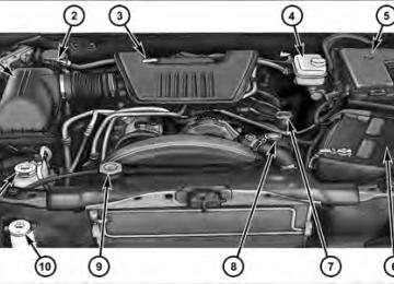
UNDERSTANDING YOUR INSTRUMENT PANEL 177
1 — Headlight Switch 2 — Air Outlets 3 — Demister Outlets 4 — Instrument Cluster 5 — Airbags
6 — Glove Compartment 7 — Radio 8 — Climate Controls 9 — Power Outlet 10 — Heated Seat Switches*
11 — Transfer Case Switch* 12 — Speed Control Switches 13 — Hood Release 14 — Parking Brake Release * If Equipped
178 UNDERSTANDING YOUR INSTRUMENT PANEL INSTRUMENT CLUSTER
INSTRUMENT CLUSTER DESCRIPTIONS
1. Fuel Gauge The fuel gauge shows the level of fuel in the fuel tank when ignition switch is in the ON/RUN position. 2. Temperature Gauge The temperature gauge shows engine coolant tempera- ture. Any reading within the normal range indicates that the engine cooling system is operating satisfactorily. The gauge pointer will likely indicate a higher temperature when driving in hot weather, up mountain grades, or when towing a trailer. It should not be allowed to exceed the upper limits of the normal operating range.
CAUTION!
Do not leave your vehicle unattended with the en- gine running as you would not be able to react to the temperature gauge if the engine overheats.
UNDERSTANDING YOUR INSTRUMENT PANEL 179
3. Turn Signal Indicators
When a turn signal is activated, a right-pointing or left-pointing arrow lights up and flashes to indicate the direction of the turn. These indicators also indicate proper operation of the front and rear turn signal lights. If either indicator flashes at a faster rate than normal, check for a defective bulb. If either indicator fails to light up when the lever is moved, check for a defective fuse or turn signal LED. A single chime is activated when the left/right turn signal is left on, with the vehicle speed greater than 15 mph (24 km/h) for more than 1 mile (1.6 km). 4. Low Fuel Warning Light
The low fuel warning light will illuminate when the fuel gauge reads 1/8 of a tank or less. There is a pointer on the side of this symbol that indicates the
side that your fuel filler door is located.
180 UNDERSTANDING YOUR INSTRUMENT PANEL 5. High Beam Indicator
The high beam indicator will illuminate if the headlights are on high beam.
6. Seat Belt Reminder Light
When the ignition switch is first turned to ON/ RUN, this light will turn on for four to eight seconds as a bulb check. During the bulb check, if the driver’s seat belt is unbuckled, a chime will sound. After the bulb check or when driving, if the driver seat belt remains unbuckled, the Seat Belt Warning Light will flash or remain on continuously. Refer to “Occupant Restraints” in “Things To Know Before Starting Your Vehicle” for further information. 7. Engine Temperature Warning Light
This light warns of an overheated engine condi- tion. As temperatures rise and the gauge ap- proaches H (Hot), this indicator will illuminate and a single chime will sound after reaching a set
threshold. Further overheating will cause the tempera- ture gauge to pass H (Hot), the indicator will continu- ously flash and a continuous chime will occur until the engine is allowed to cool.
CAUTION!
Driving with a hot engine cooling system could damage your vehicle. If the temperature light is on, safely pull over and stop the vehicle. Idle the vehicle in neutral with the air conditioner turned off until the light turns off. If the light remains on, turn the engine off immediately, and call for service.
WARNING!
A hot engine cooling system is dangerous. You or others could be badly burned by steam or boiling coolant. You may want to call a service center if your vehicle overheats. If you decide to look under the hood yourself, see “Maintaining Your Vehicle”. Fol- low the warnings under the Cooling System Pressure Cap paragraph.
8. Speedometer The speedometer shows the vehicle’s speed. 9. Charging System Light
This light shows the status of the electrical charg- ing system. The light should come on when the ignition switch is first turned to ON/RUN and remain on briefly as a bulb check. If the light stays on or comes on while driving, turn off some of the vehicle’s non-essential electrical devices or increase engine speed (if at idle). If
UNDERSTANDING YOUR INSTRUMENT PANEL 181
the charging system light remains on, it means that the vehicle is experiencing a problem with the charging system. Obtain SERVICE IMMEDIATELY. See an autho- rized dealer. If jump starting is required, refer to “Jump Starting Procedures” in “What To Do In Emergencies”. 10. Vehicle Security LightThe vehicle security light will flash rapidly for approximately 15 seconds when the vehicle security alarm is arming. The light will flash at a slower speed continuously after the alarm is set. The security light will also come on for about three seconds when the ignition is first turned to ON/RUN. 11. Anti-Lock Brake (ABS) Light
This light monitors the Anti-Lock Brake System (ABS). The light will illuminate when the igni- tion switch is turned to the ON/RUN position and may stay on for as long as four seconds.
182 UNDERSTANDING YOUR INSTRUMENT PANEL If the ABS light remains on or turns on while driving, it indicates that the Anti-Lock portion of the brake system is not functioning and that service is required. However, the conventional brake system will continue to operate normally if the BRAKE warning light is not on. If the ABS light is on, the brake system should be serviced as soon as possible to restore the benefits of Anti-Lock brakes. If the ABS light does not illuminate when the ignition switch is turned to the ON/RUN position, have the light inspected by an authorized dealer. 12. Oil Pressure Warning Light
The Oil Pressure Warning Light illuminates when the engine oil pressure has become too low. For a bulb check, this light will come on momentarily when the ignition is turned to ON/RUN. If the light turns on while driving, stop the vehicle and shut off the engine as soon as possible. Immediate service should be obtained.
13. Tachometer The tachometer gauge measures engine revolutions-per- minute (RPM x 1000). 14. Shift Lever Indicator The electronic shift lever indicator is self-contained within the instrument cluster. It displays the position of the automatic transmission shift lever, and the relation of each position to all other positions. The display will place a box around the selected transmission range (PRND21). If the PRNDL displays only the characters PRND21 (no boxes), have the system checked by an authorized dealer. 15. Trip Odometer The trip odometer shows individual trip mileage. To switch from odometer to trip odometer, press and release the trip odometer button. To reset a trip odometer, display the trip odometer then push and hold the button until the display resets (ap- proximately two seconds).
Vehicle Odometer Messages When the appropriate conditions exist, the following messages will display in the odometer:
door . . . . . . . . . . . . . . . . . . . . . . . . . . . . . Door Ajar gASCAP . . . . . . . . . . . . . . . . . . . . . . . Fuel Cap Fault LoW tirE. . . . . . . . . . . . . . . . . . . . . Low Tire Pressure noFUSE . . . . . . . . . . . . . . . . . . . . . . . . . . Fuse Fault CHAngE OIL . . . . . . . . . . . . . . . Oil Change Required On vehicles equipped with a Overhead Console with Compass/Temperature Mini-Trip Computer, some ve- hicle messages may display in the Overhead Console with Compass/Temperature Mini-Trip Computer when the appropriate conditions exist. Refer to Overhead Con- sole with Compass/Temperature Mini-Trip Computer in “Understanding The Features Of Your Vehicle” for fur- ther information.
UNDERSTANDING YOUR INSTRUMENT PANEL 183
gASCAP If the vehicle diagnostic system determines that the fuel filler cap is loose, improperly installed, or damaged, a “gASCAP” message will display in the odometer display area. Tighten the fuel filler cap properly and press the TRIP ODOMETER button to turn off the message. If the problem continues, the message will appear the next time the vehicle is started. LoW tirE When the appropriate condition exists, the odometer display will toggle between LoW and tirE for three cycles. noFUSE If the vehicle diagnostic system determines that the Ignition Off Draw (IOD) fuse is improperly installed, or
184 UNDERSTANDING YOUR INSTRUMENT PANEL damaged, a “noFUSE” message will display in the odom- eter display area. For further information on fuses and fuse locations refer to “Fuses” in “Maintaining Your Vehicle”. CHAngE OIL Message Your vehicle is equipped with an engine oil change indicator system. The “CHAngE OIL” message will flash in the instrument cluster odometer for approximately 12 seconds after a single chime has sounded, to indicate the next scheduled oil change interval. The engine oil change indicator system is duty cycle based, which means the engine oil change interval may fluctuate dependent upon your personal driving style. Unless reset, this message will continue to display each time you turn the ignition switch to the ON/RUN position. To turn off the message temporarily, press and release the Trip Odometer button on the instrument
cluster. To reset the oil change indicator system (after performing the scheduled maintenance), refer to the following procedure:
1. Turn the ignition switch to the ON/RUN position (do not start the engine). 2. Fully depress the accelerator pedal slowly three times within 10 seconds. 3. Turn the ignition switch to the OFF/LOCK position. If the indicator message illuminates when you NOTE: start the vehicle, the oil change indicator system did not reset. If necessary, repeat this procedure. 16. Odometer Display The odometer display shows the total distance the ve- hicle has been driven. U.S. Federal regulations require that upon transfer of vehicle ownership, the seller certify to the purchaser the
correct mileage that the vehicle has been driven. If your odometer needs to be repaired or serviced, the repair technician should leave the odometer reading the same as it was before the repair or service. If s/he cannot do so, then the odometer must be set at zero, and a sticker must be placed in the door jamb stating what the mileage was before the repair or service. It is a good idea for you to make a record of the odometer reading before the repair/ service, so that you can be sure that it is properly reset, or that the door jamb sticker is accurate if the odometer must be reset at zero. 17. Front Fog Light Indicator — If Equipped
The fog light indicator illuminates when the front fog lights are on.
18. Transmission Temperature Warning Light
This light indicates that there is excessive trans- mission fluid temperature, that might occur with severe usage such as trailer towing. If this
UNDERSTANDING YOUR INSTRUMENT PANEL 185
light comes on, stop the vehicle and run the engine at idle or faster with the transmission in NEUTRAL, until the light goes off.CAUTION!
Continuous driving with the Transmission Tempera- ture Warning Light illuminated will eventually cause severe transmission damage or transmission failure.
WARNING!
If the Transmission Temperature Warning Light is illuminated and you continue operating the vehicle, in some circumstances you could cause the fluid to boil over, come in contact with hot engine or exhaust components and cause a fire.
186 UNDERSTANDING YOUR INSTRUMENT PANEL 19. Electronic Throttle Control (ETC) – If Equipped
The Electronic Throttle Control (ETC) light informs you of a problem with the ETC system. If a problem is detected, the light will come on while the engine is running. If the light remains lit with the engine running, your vehicle will usually be drivable; however, see an authorized dealer for service as soon as possible. If the light is flashing when the engine is running, immediate service is required and you may experience reduced performance, an elevated/rough idle or engine stall, and your vehicle may require towing. The light will come on when the ignition is first turned to ON/RUN and remain on for 15 seconds as a bulb check. If the light does not come on during starting, have the system checked by an authorized dealer.
20. Brake Warning Light
This light monitors various brake functions, including brake fluid level and parking brake application. If the brake light turns on it may indicate that the parking brake is applied, that the brake fluid level is low, or that there is a problem with the anti-lock brake system reservoir. If the light remains on when the parking brake has been disengaged, and the fluid level is at the full mark on the master cylinder reservoir, it indicates a possible brake hydraulic system malfunction or that a problem with the Brake Booster has been detected by the Anti-Lock Brake System (ABS) / Electronic Stability Program (ESP) sys- tem. In this case, the light will remain on until the condition has been corrected. If the problem is related to the brake booster, the ABS pump will run when applying the brake and a brake pedal pulsation may be felt during each stop.
The dual brake system provides a reserve braking capac- ity in the event of a failure to a portion of the hydraulic system. A leak in either half of the dual brake system is indicated by the Brake Warning Light which will turn on when the brake fluid level in the master cylinder has dropped below a specified level. The light will remain on until the cause is corrected. NOTE: The light may flash momentarily during sharp cornering maneuvers which change fluid level condi- tions. The vehicle should have service performed, and the brake fluid level checked. If brake failure is indicated, immediate repair is neces- sary.
UNDERSTANDING YOUR INSTRUMENT PANEL 187
WARNING!
Driving a vehicle with the red brake light on is dangerous. Part of the brake system may have failed. It will take longer to stop the vehicle. You could have a collision. Have the vehicle checked immediately.
Vehicles equipped with the Anti-Lock Brake System (ABS), are also equipped with Electronic Brake Force Distribution (EBD). In the event of an EBD failure, the Brake Warning Light will turn on along with the ABS Light. Immediate repair to the ABS system is required. Operation of the Brake Warning Light can be checked by turning the ignition switch from the OFF position to the ON/RUN position. The light should illuminate for ap- proximately two seconds. The light should then turn off unless the parking brake is applied or a brake fault is detected. If the light does not illuminate, have the light inspected by an authorized dealer.
188 UNDERSTANDING YOUR INSTRUMENT PANEL The light also will turn on when the parking brake is applied with the ignition switch in the ON/RUN posi- tion. NOTE: This light shows only that the parking brake is applied. It does not show the degree of brake application. 21. Malfunction Indicator Light (MIL)
The Malfunction Indicator Light (MIL) is part of an Onboard Diagnostic system (OBD II) that monitors the emissions and engine control sys- tem. If the vehicle is ready for emissions testing, the light will come on when the ignition is first turned to ON/ RUN and remain on, as a bulb check, until the engine is started. If the vehicle is not ready for emissions testing, the light will come on when the ignition is first turned to ON/RUN and remain on for 15 seconds, then blink for 5 seconds, and remain on until the vehicle is started. If the bulb does not come on during starting, have the condition investigated promptly.
If this light comes on and remains on while driving, it suggests a potential engine control problem and the need for system service. Although your vehicle will usually be drivable and not need towing, see an authorized dealer for service as soon as possible.
CAUTION!
Prolonged driving with the MIL on could cause damage to the engine control system. It also could affect fuel economy and drivability. If the MIL is flashing, severe catalytic converter damage and power loss will soon occur. Immediate service is required.
WARNING!
A malfunctioning catalytic converter, as referenced above, can reach higher temperatures than in normal operating conditions. This can cause a fire if you drive slowly or park over flammable substances such as dry plants, wood, cardboard, etc. This could result in death or serious injury to the driver, occupants or others.
22. Tire Pressure Monitoring Telltale Light
Each tire, including the spare (if provided), should be checked monthly when cold and inflated to the inflation pressure recommended by the vehicle manufacturer on the vehicle placard or tire inflation pressure label. (If your vehicle has tires of a different size than the size indicated on the
UNDERSTANDING YOUR INSTRUMENT PANEL 189
vehicle placard or tire inflation pressure label, you should determine the proper tire inflation pressure for those tires.) As an added safety feature, your vehicle has been equipped with a Tire Pressure Monitoring System (TPMS) that illuminates a low tire pressure telltale when one or more of your tires is significantly under-inflated. Accordingly, when the low tire pressure telltale illumi- nates, you should stop and check your tires as soon as possible, and inflate them to the proper pressure. Driving on a significantly under-inflated tire causes the tire to overheat and can lead to tire failure. Under-inflation also reduces fuel efficiency and tire tread life, and may affect the vehicle’s handling and stopping ability. Please note that the TPMS is not a substitute for proper tire maintenance, and it is the driver’s responsibility to190 UNDERSTANDING YOUR INSTRUMENT PANEL maintain correct tire pressure, even if under-inflation has not reached the level to trigger illumination of the TPMS low tire pressure telltale. Your vehicle has also been equipped with a TPMS malfunction indicator to indicate when the system is not operating properly. The TPMS malfunction indicator is combined with the low tire pressure telltale. When the system detects a malfunction, the telltale will flash for approximately one minute and then remain continuously illuminated. This sequence will continue upon subse- quent vehicle start-ups as long as the malfunction exists. When the malfunction indicator is illuminated, the sys- tem may not be able to detect or signal low tire pressure as intended. TPMS malfunctions may occur for a variety of reasons, including the installation of replacement or alternate tires or wheels on the vehicle that prevent the TPMS from functioning properly. Always check the TPMS malfunction telltale after replacing one or more
tires or wheels on your vehicle, to ensure that the replacement or alternate tires and wheels allow the TPMS to continue to function properly.
CAUTION!
The TPMS has been optimized for the original equipment tires and wheels. TPMS pressures and warning have been established for the tire size equipped on your vehicle. Undesirable system opera- tion or sensor damage may result when using re- placement equipment that is not of the same size, type, and/or style. Aftermarket wheels can cause sensor damage. Do not use tire sealant from a can or balance beads if your vehicle is equipped with a TPMS, as damage to the sensors may result.
23. Airbag Warning Light
This light will turn on for four to eight seconds as a bulb check when the ignition switch is first turned to ON/RUN. If the light is either not on during starting, stays on, or turns on while driving, then have the system inspected at an authorized dealer as soon as possible. Refer to “Occupant Restraints” in “Things To Know Before Starting Your Vehicle” for further information. 24. 4WD Indicator
This light indicates the vehicle is in four-wheel drive and 4LOCK. 4WD allows all four wheels to receive torque from the engine simultane- ously.
25. SVC (Service) 4WD Indicator The SVC 4WD illuminates when the ignition key is turned to the ON/RUN position and will stay on for two
UNDERSTANDING YOUR INSTRUMENT PANEL 191
seconds. If the light stays on or illuminates during driving, it means that the 4WD system is not functioning properly and that service is required. 26. Cruise Indicator The cruise indicator illuminates when the electronic speed control system is turned on. 27. Cargo LampThe Cargo Lamp indicator will illuminate when the Cargo Lamp is activated by pressing the CARGO button, located on the headlight switch. 28. TOW/HAUL The TOW/HAUL button is located at the end of the gear shift lever. This light will illuminate when the TOW/ HAUL button has been selected.
192 UNDERSTANDING YOUR INSTRUMENT PANEL 29. 4WD LOW Indicator
This light alerts the driver that the vehicle is in the four-wheel drive LOW mode. The front and rear driveshafts are mechanically locked to- gether forcing the front and rear wheels to rotate at the same speed. Low range provides a greater gear reduction ratio to provide increased torque at the wheels. 30. Odometer/Trip Odometer Button Press the ODOMETER/TRIP ODOMETER button to toggle between the odometer and the trip odometer display. Holding the button in, resets the trip odometer reading.
MEDIA CENTER 230 (REQ) — AM/FM STEREO RADIO AND 6–DISC CD/DVD CHANGER (MP3/WMA AUX JACK)
NOTE: The radio sales code is located on the lower right side of the radio faceplate.
Media Center 230 (REQ) Operating Instructions - Radio Mode
NOTE: The ignition switch must be in the ON or ACC position to operate the radio.
Power Switch/Volume Control (Rotary) Push the ON/VOLUME control knob to turn on the radio. Press the ON/VOLUME control knob a second time to turn off the radio. Electronic Volume Control The electronic volume control turns continuously (360
degrees) in either direction without stopping. Turning the ON/VOLUME control knob to the right increases the volume and to the left decreases it. When the audio system is turned ON, the sound will be set at the same volume level as last played. SEEK Buttons Press and release the SEEK buttons to search for the next listenable station in AM/FM mode. Press the right switch to seek up and the left switch to seek down. The radio will remain tuned to the new station until you make another selection. Holding either button will bypass stations without stopping until you release it.UNDERSTANDING YOUR INSTRUMENT PANEL 193
SCAN Button Pressing the SCAN button causes the tuner to search for the next listenable station in AM, FM or Satellite (if equipped) frequencies, pausing for five seconds at each listenable station before continuing to the next. To stop the search, press the SCAN button a second time. Voice Command Button Uconnect™ Phone — If Equipped Press this button to operate the Uconnect™ Phone feature (if equipped). Refer to “Voice Command in the Uconnect™ User Manual located on the DVD for further details. If your vehicle is not equipped with or this feature is not available on your vehicle, a “Not Equipped With Uconnect Phone” message will display on the radio screen.
194 UNDERSTANDING YOUR INSTRUMENT PANEL Phone Button Uconnect™ Phone — If Equipped Press this button to operate the Uconnect™ Phone feature (if equipped). Refer to “Uconnect™ Phone” in the Uconnect™ User Manual located on the DVD for further details. If your vehicle is not equipped with or this feature is not available on your vehicle, a “Not Equipped With Uconnect Phone” message will display on the radio screen. TIME Button Press the TIME button to alternate locations of the time and frequency display. Clock Setting Procedure 1. Press and hold the TIME button until the hours blink. 2. Adjust the hours by turning the right side TUNE/ SCROLL control knob.
3. After adjusting the hours, press the right side TUNE/ SCROLL control knob to set the minutes. The minutes will begin to blink. the minutes using the right side TUNE/ 4. Adjust SCROLL control knob. Press the TUNE/SCROLL control knob to save the time change. 5. To exit, press any button/knob or wait five seconds. The clock can also be set by pressing the SETUP button and selecting the “SET HOME CLOCK” entry. Once in this display follow the above procedure, starting at step 2. INFO Button Press the INFO button for an RDS station (one with call letters displayed). The radio will return a Radio Text message broadcast from an FM station (FM mode only).
RW/FF Pressing the RW (Rewind) or FF (Fast Forward) buttons causes the tuner to search for the next frequency in the direction of the arrows. This feature operates in AM, FM or Satellite (if equipped) frequencies. TUNE Control Turn the rotary TUNE/SCROLL control knob clockwise to increase or counterclockwise to decrease the frequency. Setting the Tone, Balance, and Fade Push the rotary TUNE/SCROLL control knob and BASS will display. Turn the TUNE/SCROLL control knob to the right or left to increase or decrease the bass tones. Push the rotary TUNE/SCROLL control knob a second time and MID will display. Turn the TUNE/SCROLL control knob to the right or left to increase or decrease the mid-range tones.
UNDERSTANDING YOUR INSTRUMENT PANEL 195
Push the rotary TUNE/SCROLL control knob a third time and TREBLE will display. Turn the TUNE/SCROLL control knob to the right or left to increase or decrease the treble tones. Push the rotary TUNE/SCROLL control knob a fourth time and BALANCE will display. Turn the TUNE/ SCROLL control knob to the right or left to adjust the sound level from the right or left side speakers. Push the rotary TUNE/SCROLL control knob a fifth time and FADE will display. Turn the TUNE/SCROLL control knob to the left or right to adjust the sound level between the front and rear speakers. Push the rotary TUNE/SCROLL control knob again to exit setting tone, balance, and fade. MUSIC TYPE Button Pressing this button once will turn on the Music Type mode for five seconds. Pressing the MUSIC TYPE button196 UNDERSTANDING YOUR INSTRUMENT PANEL or turning the TUNE/SCROLL control knob within five seconds will allow the program format type to be se- lected. Many radio stations do not currently broadcast Music Type information. Toggle the MUSIC TYPE button to select the following format types:
Program Type
No program type or un-
defined
Adult Hits Classical
Classic Rock
College Country
Foreign Language
Information
16-Digit Character
Display
None
Adlt Hit Classicl Cls Rock College Country Language
Inform
Program Type
Jazz News
Nostalgia
Oldies
Personality
Public
Rhythm and Blues Religious Music Religious Talk
Rock Soft
Soft Rock
Soft Rhythm and Blues
Sports Talk
16-Digit Character
Display
Jazz News
Nostalga Oldies Persnlty Public R & B
Rel Musc Rel Talk
Rock Soft
Soft Rck Soft R & B
Sports Talk
Program Type
Top 40
Weather16-Digit Character
Display Top 40
WeatherBy pressing the SEEK button when the Music Type icon is displayed, the radio will be tuned to the next frequency station with the same selected Music Type name. The Music Type function only operates when in the FM mode. If a preset button is activated while in the Music Type (Program Type) mode, the Music Type mode will be exited and the radio will tune to the preset station. SETUP Button Pressing the SETUP button allows you to select between the following items:
UNDERSTANDING YOUR INSTRUMENT PANEL 197
NOTE: Turn the TUNE/SCROLL control knob to scroll through the entries. Push the AUDIO/SELECT button to select an entry and make changes. • DVD Enter - When the disc is in DVD Menu mode, selecting DVD Enter will allow you to play the current highlighted selection. Use the remote control to scroll up and down the menu (if equipped). • DISC Play/Pause - You can toggle between playing the DVD and pausing the DVD by pushing the SELECT button (if equipped). • DVD Play Options - Selecting the DVD Play Options will display the following: • Subtitle – Repeatedly pressing SELECT will switch subtitles to different subtitle languages that are available on the disc (if equipped).198 UNDERSTANDING YOUR INSTRUMENT PANEL
• Audio Stream – Repeatedly pressing SELECT will switch to different audio languages (if supported on the disc) (if equipped). • Angle – Repeatedly pressing SELECT will change the viewing angle if supported by the DVD disc (if equipped).
varies depending upon the disc.
NOTE: • The available selections for each of the above entries • These selections can only be made while playing a • VES™ Power - Allows you to turn VES™ ON and • VES™ Lock - Locks out rear VES™ remote controls (if
OFF (if equipped).
DVD.
equipped).
• VES™ CH1/CH2 - Allows the user to change the mode of either the IR1 or IR2 wireless headphones by pressing the AUDIO/SELECT button (if equipped). • Set Home Clock - Pressing the SELECT button allows you to set the clock. Turn the TUNE/SCROLL control knob to adjust the hours and then press and turn the TUNE/SCROLL control knob to adjust the minutes. Press the TUNE/SCROLL control knob again to save changes. • Player Defaults - Selecting this item will allow the user to scroll through the following items and set defaults according to customer preference.
Menu Language — If Equipped Selecting this item will allow the user to choose the default startup DVD menu language (effective only if language supported by disc). If you want to select a language not listed, then scroll down and select ⬙other.⬙
Enter the four-digit country code using the TUNE/ SCROLL control knob to scroll up and down to select the number and then push to select. Audio Language — If Equipped Selecting this item allows you to choose a default audio language (effective only if the language is supported by the disc). You can select a language not listed by scrolling down and selecting ⬙other.⬙ Enter the country code using the TUNE/SCROLL control knob to scroll up and down to select the number and then push to select. Subtitle Language — If Equipped Selecting this item allows you to choose a default subtitle language (effective only if the language is supported by the disc). You can select a language not listed by scrolling down and selecting ⬙other.⬙ Enter the country code using the TUNE/SCROLL control knob to scroll up and down to select the number and then push to select.
UNDERSTANDING YOUR INSTRUMENT PANEL 199
Subtitles — If Equipped Selecting this item allows you to choose between subtitle Off or On. Audio DRC — If Equipped Selecting this item allows you to limit maximum audio dynamic range. The default is set to ⬙High,⬙ and under this setting, dialogues will play at 11 db higher than if the setting is ⬙Normal.⬙ Aspect Ratio — If Equipped Selecting this item allows you to choose between wide screen, pan scan, and letter box. AutoPlay — If Equipped When this is set to On and a DVD video is inserted, it will bypass the DVD menu screen and automatically play the movie. In some rare cases, the DVD player may not auto-play the main title. In such cases, use the MENU button on the remote control to select desired title to play.
200 UNDERSTANDING YOUR INSTRUMENT PANEL NOTE: The user will have to set these defaults before loading a disc. If changes are made to these settings after a disc is loaded, changes will not be effective. Also, the defaults are effective only if the disc supports the customer-preferred settings. AM and FM Buttons Press the buttons to select AM or FM mode. SET Button — To Set the Pushbutton Memory When you are receiving a station that you wish to commit to pushbutton memory, press the SET button. The symbol SET 1 will now show in the display window. Select the button (1-6) you wish to lock onto this station and press and release that button. If a button is not selected within five seconds after pressing the SET but- ton, the station will continue to play but will not be stored into pushbutton memory. You may add a second station to each pushbutton by repeating the above procedure with this exception: Press
the SET button twice and SET 2 will show in the display window. Each button can be set for SET 1 and SET 2 in both AM and FM. This allows a total of 12 AM, 12 FM, and 12 Satellite (if equipped) stations to be stored into pushbutton memory. The stations stored in SET 2
memory can be selected by pressing the pushbutton twice. Every time a preset button is used, a corresponding button number will display. Buttons 1 - 6
These buttons tune the radio to the stations that you commit to pushbutton memory {12 AM, 12 FM, and 12
Satellite (if equipped) stations}. DISC Button Pressing the DISC button will allow you to switch from AM/FM modes to Disc modes.Operation Instructions - (DISC MODE for CD and MP3/WMA Audio Play, DVD-VIDEO) The radio DVD player and many DVD discs are coded by geographic region. These region codes must match in order for the disc to play. If the region code for the DVD disc does not match the region code for the radio DVD player, it will not play the disc. Customers may take their vehicle to an authorized dealer to change the region code of the player a maximum of five times.
CAUTION!
The radio may shut down during extremely hot conditions. When this occurs, the radio will indicate “Disc Hot” and shut off until a safe temperature is reached. This shutdown is necessary to protect the optics of the DVD player and other radio internal components.
UNDERSTANDING YOUR INSTRUMENT PANEL 201
NOTE: The ignition switch must be in the ON or ACC position to operate the radio. LOAD Button — Loading Compact Disc(s) Press the LOAD button and the pushbutton with the corresponding number (1-6) where the CD is being loaded. The radio will display PLEASE WAIT and prompt when to INSERT DISC. After the radio displays ⬙INSERT DISC,⬙ insert the CD into the player. Radio display will show ⬙LOADING DISC⬙ when the disc is loading and “READING DISC” when the radio is reading the disc.CAUTION!
This CD player will accept 4–3/4 in (12 cm) discs only. The use of other sized discs may damage the CD player mechanism.
202 UNDERSTANDING YOUR INSTRUMENT PANEL Eject Button — Ejecting Compact Disc(s)
Press the EJECT button and the pushbutton with the corresponding number (1-6) where the CD was loaded and the disc will unload and move to the entrance for easy removal. Radio display will show ⬙EJECTING DISC⬙ when the disc is being ejected and prompt the user to remove the disc. Press and hold the EJECT button for five seconds and all CDs will be ejected from the radio. The disc can be ejected with the radio and ignition OFF. SEEK Button (CD MODE) Press the right SEEK button for the next selection on the CD. Press the left SEEK button to return to the beginning of the current selection, or return to the beginning of the previous selection if the CD is within the first second of the current selection. Pressing and holding the SEEK button will allow you to scroll through the tracks faster in CD and MP3/MWA modes.
SCAN Button (CD MODE) Press the SCAN button to scan through each track on the CD currently playing. TIME Button (CD MODE) Press this button to change the display from a large CD playing time display to a small CD playing time display. RW/FF (CD MODE) Press and hold FF (Fast Forward) and the CD player will begin to fast forward until FF is released, or RW or another CD button is pressed. The RW (Rewind) button works in a similar manner. AM or FM Button (CD MODE) Switches the radio into the AM or FM radio mode.
Notes On Playing MP3/WMA Files The radio can play MP3/WMA files; however, acceptable MP3/WMA file recording media and formats are limited. When writing MP3/WMA files, pay attention to the following restrictions. Supported Media (Disc Types) The MP3/WMA file recording media supported by the radio are CDDA, CD-R, CD-RW, MP3,WMA, DVD Video, DVD-R, DVD-RW, DVD+R, DVD+RW, and CDDA+MP3. Supported Medium Formats (File Systems) The medium formats supported by the radio are ISO 9660
Level 1 and Level 2 and includes the Joliet extension. When reading discs recorded using formats other than ISO 9660 Level 1 and Level 2, the radio may fail to read files properly and may be unable to play the file nor- mally. UDF and Apple HFS formats are not supported.UNDERSTANDING YOUR INSTRUMENT PANEL 203
The radio uses the following limits for file systems: • Maximum number of directory levels: 8
• Maximum number of files: 255
• Maximum number of folders: 100
• Maximum number of characters in file/folder names: • Level 1: 12 (including a separator ⬙.⬙ and a three- • Level 2: 31 (including a separator ⬙.⬙ and a three-character extension)
character extension)
Multisession disc formats are supported by the radio. Multisession discs may contain combinations of normal CD audio tracks and computer files (including MP3/ WMA files). Discs created with an option such as ⬙keep disc open after writing⬙ are most likely multisession discs. The use of multisession for CD audio or MP3/ WMA playback may result in longer disc loading times.
204 UNDERSTANDING YOUR INSTRUMENT PANEL If a disc contains multi-formats, such as CD audio and MP3/WMA tracks, the radio will only play the MP3/ WMA tracks on that disc. Supported MP3/WMA File Formats The radio will recognize only files with the *.MP3/WMA extension as MP3/WMA files. Non-MP3/WMA files named with the *.MP3/WMA extension may cause play- back problems. The radio is designed to recognize the file as an invalid MP3/WMA and will not play the file. When using the MP3/WMA encoder to compress audio data to an MP3/WMA file, the bit rate and sampling frequencies in the following table are supported. In addition, variable bit rates (VBR) are also supported. The majority of MP3/WMA files use a 44.1 kHz sampling rate and a 192, 160, 128, 96 or VBR bit rates.
MPEG
Specification
Sampling Fre- quency (kHz)
MPEG-1 Audio
Layer 3
48, 44.1, 32
MPEG-2 Audio
Layer 3
24, 22.05, 16
WMA
Specification
Sampling Fre- quency (kHz)
WMA
44.1 and 48
Bit Rate (kbps)
320, 256, 224, 192, 160, 128, 112, 96, 80, 64,
56, 48
160, 128, 144, 112, 96, 80, 64,
56, 48
Bit Rate (kbps)
48, 64, 96, 128, 160, 192 VBR
ID3 Tag information for artist, song title, and album title are supported for ID3 version 1 tags. ID3 version 2 is not supported by the radios. Playlist files are not supported. MP3 Pro files are not supported.
Playback of MP3/WMA Files When a medium containing MP3/WMA data is loaded, the radio checks all files on the medium. If the medium contains a lot of folders or files, the radio will take more time to start playing the MP3/WMA files. Loading times for playback of MP3/WMA files may be affected by the following: • Media - CD-RW media may take longer to load than • Medium formats - Multisession discs may take longer • Number of files and folders - Loading times will
to load than non-multisession discs
CD-R media
increase with more files and folders
To increase the speed of disc loading, it is recommended to use CD-R media and single-session discs. To create a single-session disc, enable the “Disc at Once” option before writing to the disc.
UNDERSTANDING YOUR INSTRUMENT PANEL 205
LIST Button (DISC Mode for MP3/WMA Play) Pressing the LIST button will bring up a list of all folders on the disc. Scrolling up or down the list is done by turning the TUNE/SCROLL control knob. Selecting a folder by pressing the TUNE/SCROLL control knob will begin playing the files contained in that folder (or the next folder in sequence if the selection does not contain playable files). The folder list will time out after five seconds. INFO Button (DISC Mode for MP3/WMA Play) Pressing the INFO button repeatedly will scroll through the following TAG information: Song Title, Artist, File Name, and Folder Name (if available). Press the INFO button once more to return to ⬙elapsed time⬙ priority mode. Press and hold the INFO button for three seconds or more and radio will display song titles for each file.
206 UNDERSTANDING YOUR INSTRUMENT PANEL Press and hold the INFO button again for three seconds to return to ⬙elapsed time⬙ display. Operation Instructions - Auxiliary Mode The auxiliary (AUX) jack is an audio input jack which allows the user to plug in a portable device such as an MP3/WMA player, cassette player, or microphone and utilize the vehicle’s audio system to amplify the source and play through the vehicle speakers. Pressing the AUX button will change the mode to auxil- iary device if the AUX jack is connected. NOTE: The AUX device must be turned on and the device’s volume set to the proper level. If the AUX audio is not loud enough, turn the device’s volume up. If the AUX audio sounds distorted, turn the device’s volume down. SEEK Button (Auxiliary Mode) No function.
SCAN Button (Auxiliary Mode) No function. EJECT Button (Auxiliary Mode)
No function.
TIME Button (Auxiliary Mode) Press the TIME button to change the display from elapsed playing time to time of day. The time of day will display for five seconds. RW/FF (Auxiliary Mode) No function. SET Button (Auxiliary Mode) No function.
Operating Instructions — Voice Command System (If Equipped) For the radio, Refer to “Voice Command” in the Uconnect™ User Manual located on the DVD for further details. Operating Instructions - Uconnect™ Phone (If Equipped) Refer to “Uconnect™ Phone” in the Uconnect™ User Manual located on the DVD for further details. Operating Instructions - Video Entertainment System (VES)™ (If Equipped) Refer to “Video Entertainment System (VES)™” in the Uconnect™ User Manual located on the DVD for further details. Dolby威 Manufactured under license from Dolby威 Laboratories. ⬙Dolby威⬙ and the double-D symbol are trademarks of Dolby威 Laboratories.
UNDERSTANDING YOUR INSTRUMENT PANEL 207
Macrovision This product incorporates copyright protection technol- ogy that is protected by U.S. patents and other intellec- tual property rights. Use of this copyright protection technology must be authorized by Macrovision, and is intended for home and other limited viewing uses only, unless otherwise authorized by Macrovision. Reverse engineering or disassembly is prohibited. DTS™ ⬙DTS™⬙ and ⬙DTS™ 2.0⬙ are trademarks of Digital The- ater Systems, Inc. Uconnect™ Multimedia (Satellite Radio) — If Equipped Satellite radio uses direct satellite-to-receiver broadcast- ing technology to provide clear digital sound, coast to coast. The subscription service provider is Sirius Satellite Radio. This service offers over 130 channels of music,
208 UNDERSTANDING YOUR INSTRUMENT PANEL sports, news, entertainment, and programming for chil- dren, directly from its satellites and broadcasting studios. NOTE: Sirius service is not available in Hawaii and has limited coverage in Alaska. System Activation Sirius Satellite Radio service is pre-activated, and you may begin listening immediately to the one year of audio service that is included with the factory-installed satellite radio system in your vehicle. Sirius will supply a wel- come kit that contains general information, including how to setup your on-line listening account. For further information, call the toll-free number 888-539-7474, or visit the Sirius web site at www.sirius.com, or at www- .siriuscanada.ca for Canadian residents. Electronic Serial Number/Sirius Identification Number (ESN/SID) Please have the following information available when calling:
1. The Electronic Serial Number/Sirius Identification Number (ESN/SID). 2. Your Vehicle Identification Number. To access the ESN/SID, refer to the following steps: ESN/SID Access With the ignition switch in the ON/RUN or ACC posi- tion and the radio on, press the SETUP button and scroll using the TUNE/SCROLL control knob until Sirius ID is selected. Press the TUNE/SCROLL control knob and the Sirius ID number will display. The Sirius ID number display will time out in two minutes. Press any button on the radio to exit this screen. Selecting Uconnect™ Multimedia (Satellite) Mode Press the SAT button until ⬙SAT⬙ appears in the display. A CD may remain in the radio while in the Satellite radio mode.
Satellite Antenna To ensure optimum reception, do not place items on the roof around the rooftop antenna location. Metal objects placed within the line of sight of the antenna will cause decreased performance. Larger luggage items such as bikes should be placed as far rearward as possible, within the loading design of the rack. Do not place items directly on or above the antenna. Reception Quality Satellite reception may be interrupted due to one of the following reasons: • The vehicle is parked in an underground parking • Dense tree coverage may interrupt reception in the • Driving under wide bridges or along tall buildings can
structure or under a physical obstacle.
form of short audio mutes.
cause intermittent reception.
UNDERSTANDING YOUR INSTRUMENT PANEL 209
• Placing objects over or too close to the antenna can
cause signal blockage.
Operating Instructions - Uconnect™ Multimedia (Satellite) Mode NOTE: The ignition switch must be in the ON/RUN or ACC position to operate the radio. SEEK Buttons Press and release the SEEK buttons to search for the next channel in Satellite mode. Press the right switch to seek up and the left switch to seek down. The radio will remain tuned to the new channel until you make another selection. Holding either button will bypass channels without stopping until you release it.
210 UNDERSTANDING YOUR INSTRUMENT PANEL SCAN Button Pressing the SCAN button causes the tuner to search for the next channel, pausing for eight seconds before con- tinuing to the next. To stop the search, press the SCAN button a second time. INFO Button Pressing the INFO button will cycle the display informa- tion between Artist, Song Title, and Composer (if avail- able). Also, pressing and holding the INFO button for an additional three seconds will make the radio display the Song Title all of the time (press and hold again to return to normal display). RW/FF Pressing the RW (Rewind) or FF (Fast Forward) buttons causes the tuner to search for the next channel in the direction of the arrows.
TUNE Control (Rotary) Turn the rotary TUNE/SCROLL control knob clockwise to increase or counterclockwise to decrease the channel. MUSIC TYPE Button Pressing this button once will turn on the Music Type mode for five seconds. Pressing the MUSIC TYPE button or turning the TUNE/SCROLL control knob within five seconds will allow the program format type to be se- lected. Toggle the MUSIC TYPE button again to select the music type. By pressing the SEEK button when the Music Type function is active, the radio will be tuned to the next channel with the same selected Music Type name. If a preset button is activated while in the Music Type (Program Type) mode, the Music Type mode will be exited and the radio will tune to the preset channel.
SETUP Button Pressing the SETUP button allows you to select the following items: • Display Sirius ID number — Press the AUDIO/ SELECT button to display the Sirius ID number. This number is used to activate, deactivate, or change the Sirius subscription.
SET Button – To Set the Pushbutton Memory When you are receiving a channel that you wish to commit to pushbutton memory, press the SET button. The symbol SET 1 will now show in the display window. Select the button (1-6) you wish to lock onto this channel and press and release that button. If a button is not selected within five seconds after pressing the SET but- ton, the channel will continue to play but will not be stored into pushbutton memory.
UNDERSTANDING YOUR INSTRUMENT PANEL 211
You may add a second channel to each pushbutton by repeating the above procedure with this exception: Press the SET button twice and SET 2 will show in the display window. Each button can be set for SET 1 and SET 2. This allows a total of 12 Satellite channels to be stored into pushbutton memory. The channels stored in SET 2
memory can be selected by pressing the pushbutton twice. Every time a preset button is used, a corresponding button number will display. Buttons 1 - 6
These buttons tune the radio to the channels that you commit to pushbutton memory (12 Satellite stations).212 UNDERSTANDING YOUR INSTRUMENT PANEL MEDIA CENTER 130 (SALES CODE RES)
NOTE: The radio sales code is located on the lower right side of the radio faceplate.
Media Center 130 (RES)
Operating Instructions — Radio Mode
NOTE: The ignition switch must be in the ON or ACC position to operate the radio. Power Switch/Volume Control (Rotary) Push the ON/VOLUME control knob to turn on the radio. Push the ON/VOLUME control knob a second time to turn off the radio. Electronic Volume Control The electronic volume control turns continuously (360
degrees) in either direction, without stopping. Turning the ON/VOLUME control knob to the right increases the volume, and to the left decreases it. When the audio system is turned on, the sound will be set at the same volume level as last played. SEEK Buttons Press and release the SEEK buttons to search for the next listenable station in AM/FM mode. Press the right switchto seek up and the left switch to seek down. The radio will remain tuned to the new station until you make another selection. Holding either button will bypass stations without stopping, until you release it. TIME Button Press the TIME button to alternate display of the time and radio frequency. Clock Setting Procedure 1. Press and hold the TIME button until the hours blink. 2. Adjust the hours by turning the right side TUNE/ SCROLL control knob. 3. After adjusting the hours, press the right side TUNE/ SCROLL control knob to set the minutes. The minutes will begin to blink.
UNDERSTANDING YOUR INSTRUMENT PANEL 213
the minutes using the right side TUNE/ 4. Adjust SCROLL control knob. Press the TUNE/SCROLL control knob to save time change. 5. To exit, press any button/knob, or wait five seconds. RW/FF Pressing the RW (Rewind) or FF (Fast Forward) buttons causes the tuner to search for the next frequency in the direction of the arrows. This feature operates in either AM or FM frequencies. TUNE Control Turn the rotary TUNE/SCROLL control knob clockwise to increase or counterclockwise to decrease the frequency. Setting the Tone, Balance, and Fade Push the rotary TUNE/SCROLL control knob and BASS will display. Turn the TUNE/SCROLL control knob to the right or left to increase or decrease the bass tones.214 UNDERSTANDING YOUR INSTRUMENT PANEL Push the rotary TUNE/SCROLL control knob a second time and MID will display. Turn the TUNE/SCROLL control knob to the right or left to increase or decrease the mid-range tones. Push the rotary TUNE/SCROLL control knob a third time and TREBLE will display. Turn the TUNE/SCROLL control knob to the right or left to increase or decrease the treble tones. Push the rotary TUNE/SCROLL control knob a fourth time and BALANCE will display. Turn the TUNE/ SCROLL control knob to the right or left to adjust the sound level from the right or left side speakers. Push the rotary TUNE/SCROLL control knob a fifth time and FADE will display. Turn the TUNE/SCROLL control knob to the left or right to adjust the sound level between the front and rear speakers.
Push the rotary TUNE/SCROLL control knob again to exit setting tone, balance, and fade. AM/FM Button Press the buttons to select either AM or FM mode. SET/RND Button — To Set the Pushbutton Memory When you are receiving a station that you wish to commit to pushbutton memory, press the SET/RND button. The symbol SET 1 will now show in the display window. Select the button (1 to 6) you wish to lock onto this station and press and release that button. If a button is not selected within five seconds after pressing the SET/RND button, the station will continue to play but will not be stored into pushbutton memory. You may add a second station to each pushbutton by repeating the above procedure with this exception: Press the SET/RND button twice and SET 2 will show in the display window. Each button can be set for SET 1 and
SET 2 in both AM and FM. This allows a total of 12 AM and 12 FM stations to be stored into pushbutton memory. The stations stored in SET 2 memory can be selected by pressing the pushbutton twice. Every time a preset button is used, a corresponding button number will display. Buttons 1 - 6
These buttons tune the radio to the stations that you commit to pushbutton memory (12 AM and 12 FM stations). DISC Button Pressing the DISC button will allow you to switch from AM/FM modes to Disc modes.UNDERSTANDING YOUR INSTRUMENT PANEL 215
Operation Instructions — CD MODE For CD And MP3 Audio Play NOTE: • The ignition switch must be in the ON or ACC • This radio is capable of playing compact discs (CD), recordable compact discs (CD-R), rewritable compact discs (CD-RW), compact discs with MP3 tracks and multisession compact discs with CD and MP3 tracks.
position to operate the radio.
Inserting Compact Disc(s) Gently insert one CD into the CD player with the CD label facing up. The CD will automatically be pulled into the CD player and the CD icon will illuminate on the radio display. If a CD does not go into the slot more than 1.0 in (2.5 cm), a disc may already be loaded and must be ejected before a new disc can be loaded.
216 UNDERSTANDING YOUR INSTRUMENT PANEL If you insert a disc with the ignition ON and the radio ON, the unit will switch from radio to CD mode and begin to play when you insert the disc. The display will show the track number, and index time in minutes and seconds. Play will begin at the start of track 1.
CAUTION!
away and jam the player mechanism.
• This CD player will accept 4-3/4 in (12 cm) discs only. The use of other sized discs may damage the CD player mechanism.