- 2010 Dodge Dakota Owners Manuals
- Dodge Dakota Owners Manuals
- 2008 Dodge Dakota Owners Manuals
- Dodge Dakota Owners Manuals
- 2006 Dodge Dakota Owners Manuals
- Dodge Dakota Owners Manuals
- 2009 Dodge Dakota Owners Manuals
- Dodge Dakota Owners Manuals
- 2004 Dodge Dakota Owners Manuals
- Dodge Dakota Owners Manuals
- 2011 Dodge Dakota Owners Manuals
- Dodge Dakota Owners Manuals
- 2005 Dodge Dakota Owners Manuals
- Dodge Dakota Owners Manuals
- 2007 Dodge Dakota Owners Manuals
- Dodge Dakota Owners Manuals
- Download PDF Manual
-
as safe as possible: Make certain that the load is secured in the trailer and will not shift during travel. When trailering cargo that is not fully secured, dynamic load shifts can occur that may be difficult for the driver to control. You could lose control of your vehicle and have an accident. • When hauling cargo or towing a trailer, do not over- load your vehicle or trailer. Overloading can cause a loss of control, poor performance or damage to brakes, axle, engine, transmission, steering, suspension, chas- sis structure or tires.
STARTING AND OPERATING 259
• Safety chains must always be used between your vehicle and trailer. Always connect the chains to the frame or hook retainers of the vehicle hitch. Cross the chains under the trailer tongue and allow enough slack for turning corners. • Vehicles with trailers should not be parked on a grade. When parking, apply the parking brake on the tow vehicle. Put the tow vehicle automatic transmission in P for Park. With a manual transmission, shift the transmission into reverse. And with four-wheel-drive vehicles, make sure the transfer case is not in neutral. Always, block or ⬙chock⬙ the trailer wheels.
• GCWR must not be exceeded. • Total weight must be distributed between the tow vehicle and the trailer such that the following four ratings are not exceeded: 1. GVWR
260 STARTING AND OPERATING
2. GTW 3. GAWR 4. Tongue weight rating for the trailer hitch utilized (This requirement may limit the ability to always achieve the 10% to 15% range of tongue weight as a percentage of total trailer weight).
Towing Requirements — Tires − Do not attempt to tow a trailer while using a compact
spare tire.
− Proper tire inflation pressures are essential to the safe and satisfactory operation of your vehicle. Refer to the Tires–General Information section of this manual on Tire Pressures for proper tire inflation procedures.
− Check for signs of tire wear or visible tire damage before towing a trailer. Refer to the Tires–General Information section of this manual on Tread Wear Indicators for the proper inspection procedure.
− When replacing tires refer to the Tires–General Infor- mation section of this manual on Replacement Tires for proper tire replacement procedures. Replacing tires with a higher load carrying capacity will not increase the vehicle’s GVWR and GAWR limits. Towing Requirements — Trailer Brakes − Do not interconnect the hydraulic brake system or vacuum system of your vehicle with that of the trailer. This could cause inadequate braking and possible personal injury.
− Also, check the trailer tires for proper tire inflation
pressures before trailer usage.
− An electronically actuated trailer brake controller is required when towing a trailer with electronically
actuated brakes. When towing a trailer equipped with a hydraulic surge actuated brake system, an electronic brake controller is not required.
− Trailer brakes are recommended for trailers over 1,000
lbs (454 kg) and required for trailers in excess of 2,000
lbs (907 kg).CAUTION!
If the trailer weighs more than 1,000 lbs (454 kg) loaded, it should have its own brakes and they should be of adequate capacity. Failure to do this could lead to accelerated brake lining wear, higher brake pedal effort, and longer stopping distances.
STARTING AND OPERATING 261
WARNING!
Do not connect trailer brakes to your vehicle’s hy- draulic brake lines. It can overload your brake sys- tem and cause it to fail. You might not have brakes when you need them and could have an accident. Towing any trailer will increase your stopping dis- tance. When towing you should allow for additional space between your vehicle and the vehicle in front of you. Failure to do so could result in an accident.
Towing Requirements — Trailer Lights & Wiring Whenever you pull a trailer, regardless of the trailer size, stop lights and turn signals on the trailer are required for motoring safety. The Trailer Tow Package may include a 4 and 7 pin wiring harness. Use a factory approved trailer harness and connector.
262 STARTING AND OPERATING
NOTE: Do not cut or splice wiring into the vehicles wiring harness. The electrical connections are all complete to the vehicle but you must mate the harness to a trailer connector. Refer to the following illustrations.
7- Pin Connector
Towing Tips Before setting out on a trip, practice turning, stopping and backing the trailer in an area away from heavy traffic.
4 - Pin Connector
If using a manual transmission vehicle for trailer towing, all starts must be in FIRST gear to avoid excessive clutch slippage. Towing Tips — Automatic Transmission The “D” range can be selected when towing. However, if frequent shifting occurs while in this range, the “TOW HAUL” feature should be selected. NOTE: Using the “TOW HAUL” feature while operat- ing the vehicle under heavy operating conditions will improve performance and extend transmission life by reducing excessive shifting and heat build up. This action will also provide better engine braking. The automatic transmission fluid and filter should be changed if you REGULARLY tow a trailer for more than 45 minutes of continuous operation. See Schedule “B” in section 8 of this manual for transmission fluid change intervals.
STARTING AND OPERATING 263
NOTE: Check the automatic transmission fluid level before towing. Towing Tips — Tow/Haul (If Equipped) To reduce potential for automatic transmission overheat- ing, turn the “TOW HAUL” feature ON when driving in hilly areas or shift the transmission to Drive position 2 on more severe grades. Towing Tips — Electronic Speed Control (If Equipped) − Don’t use in hilly terrain or with heavy loads. − When using the speed control, if you experience speed drops greater than 10 mph (16 km/h), disengage until you can get back to cruising speed.
− Use speed control in flat terrain and with light loads to
maximize fuel efficiency.
264 STARTING AND OPERATING
Towing Tips — Cooling System To reduce potential for engine and transmission over- heating, take the following actions: − City Driving When stopped for short periods of time, put transmission in neutral and increase engine idle speed. − Highway Driving Reduce speed. − Air Conditioning Turn off temporarily. − refer to Cooling System Operating information in the Maintenance section of this manual for more informa- tion.
SNOWPLOW
Dodge Dakota Models
NOTE: Do not use Dodge Dakota Models for snowplow applications.
WARNING!
Snowplows, winches, and other aftermarket equip- ment should not be added to the front end of your vehicle. The airbag crash sensors may be affected by the change in the front end structure. The airbags could deploy unexpectedly or could fail to deploy during a collision resulting in serious injury or death.
CAUTION!
RECREATIONAL TOWING (BEHIND MOTORHOME, ETC.)
STARTING AND OPERATING 265
Using this vehicle for snowplow applications can cause damage to the vehicle.
WARNING!
Attaching a snowplow to this vehicle could ad- versely affect performance of the airbag system in an accident. Do not expect that the airbag will perform as described earlier in this manual
Recreational Towing 2WD Models Recreational towing of 2WD models is not allowable. Towing the vehicle with the transmission in Neutral can cause severe transmission damage. Removal of the drive- shaft for towing is not recommended, since this would allow fluid to drain from the transmission. Recreational Towing 4WD Models
CAUTION!
Internal damage to the transfer case will occur if a front or rear wheel lift is used when recreational towing.
266 STARTING AND OPERATING
CAUTION!
The transfer case must be shifted into Neutral (N) for recreational towing. The Neutral (N) selection but- ton is located on the lower left hand corner of the 4WD Control Switch. Shifts into and out of transfer case Neutral (N) can take place with the selector switch in any mode position. Automatic Transmissions must be placed in P (Park) position for recreational towing. Manual Transmissions must be placed in gear (for example, 4th gear) for recreational towing. Failure to follow these procedures can cause severe transmis- sion and/or transfer case damage.
Recreational Towing Procedure Use the following procedure to prepare your vehicle for recreational towing.
CAUTION!
It is necessary to follow these steps to be certain that the transfer case is fully in Neutral (N) before recreational towing to prevent damage to internal parts.
1. Bring vehicle to a complete stop. 2. Shut engine OFF. 3. Place ignition key in the ON position. 4. Depress brake pedal. 5. Shift automatic transmission to Neutral (N) or depress clutch on manual transmission.
6. Using the point of a ballpoint pen or similar object, depress the recessed transfer case Neutral (N) button for 4 seconds.
7. After shift is completed and the Neutral (N) light comes on release Neutral (N) button. 8. Start engine.
STARTING AND OPERATING 267
9. Shift automatic transmission into Reverse (R). 10. Release brake pedal for five seconds and ensure that there is no vehicle movement. 11. Repeat steps 9 and 10 with the transmission in Drive (D). 12. Shut engine OFF and place ignition key to the unlocked OFF position. 13. Shift automatic transmission into Park (P). Shift Manual transmissions into 4th gear. 14. Attach vehicle to tow vehicle with tow bar. 15. Disconnect the negative battery cable. Items 1 through 5 are requirements that must be NOTE: met prior to depressing the Neutral (N) selection button, and must continue to be met until the 4 seconds elapse and the shift has been completed. If any of these requirements (with the exception of 3 - Key ON) are not met prior to depressing the Neutral (N) button or are no longer met
268 STARTING AND OPERATING
during the 4 second timer, then the Neutral (N) indicator light will flash continuously until all requirements are met or until the Neutral (N) button is released. NOTE: The ignition key must be ON for a shift to take place and for the position indicator lights to be operable. If the key in not ON, the shift will not take place and no position indicator lights will be on or flashing. NOTE: Flashing neutral (N) position indicator light indicates that shift requirements have not been met.
CAUTION!
Damage to the transmission may occur if the trans- mission is shifted into Park (P) with the transfer case in Neutral (N) and the engine RUNNING. With the transfer case in Neutral (N), ensure that the engine is OFF prior to shifting the transmission into Park (P).
Returning to Normal Operation Use the following procedure to prepare your vehicle for normal usage. 1. Reconnect the negative battery cable. 2. The vehicle must be at a complete stop. 3. Place the ignition if the Off position (if it has been moved or the engine has been started). 4. Place ignition key in the ON position (engine Off). 5. Depress brake pedal. 6. Shift automatic transmission to Neutral (N) or depress clutch on manual transmission. 7. Using the point of a ballpoint pen or similar object, depress the recessed transfer case Neutral (N) button for 1 second.
8. After the Neutral (N) indicator light turns off release the Neutral (N) button. 9. After the Neutral (N) button has been released the transfer case will shift to the position identified by the selector switch. 10. Start the engine. Shift the automatic transmission into Drive (D), or place the manual transmission in 1st gear and momentarily release the clutch, to verify that the transfer case has engaged. 11. Set parking brake. Shift automatic transmission to Park (P) or shift manual transmission to Neutral. Items 1 through 5 are requirements that must be NOTE: met prior to depressing the Neutral (N) selection button,
STARTING AND OPERATING 269
and must continue to be met until 1 second elapses and the shift has been completed. If any of these requirements (with the exception of 3 - key ON) are not met prior to depressing the Neutral (N) button or are no longer met during the 1 second time, then all of the mode position indicator lights will flash continuously until all require- ments are met or until the Neutral (N) button is released. NOTE: The ignition key must be ON for a shift to take place and for the position indicator lights to be operable. If the key is not ON, the shift will not take place and no position indicator lights will be on or flashing. NOTE: Flashing neutral (N) position indicator light indicates that shift requirements have not been met.
270 STARTING AND OPERATING
WARNING!
You or others could be injured if you leave the vehicle unattended with the transfer case in the Neutral (N) position without first fully engaging the parking brake. The transfer case Neutral (N) position disengages both the front and rear driveshafts from the powertrain and will allow the vehicle to move despite the transmission position. The parking brake should always be applied when the driver is not in the vehicle.
CAUTION!
• Do not use a bumper mounted clamp-on tow bar on your vehicle. The bumper face bar will be damaged. • Do not disconnect the rear driveshaft because fluid will leak from the transfer case and damage internal parts.
EQUIPMENT IDENTIFICATION PLATE The equipment Identification Plate is located on the hood inner surface. The following information about your vehicle is dis- played on this plate: Model, Wheelbase, Vehicle Identifi- cation Number, Truck Order Number, and code numbers with descriptions of all production and special equip- ment on the truck as shipped from the factory. NOTE: Always refer to the equipment identification plate when ordering parts.
WHAT TO DO IN EMERGENCIES
CONTENTS
䡵 Hazard Warning Flasher . . . . . . . . . . . . . . . . . . 272
䡵 Adding Fuel . . . . . . . . . . . . . . . . . . . . . . . . . . 272
䡵 Changing A Flat Tire . . . . . . . . . . . . . . . . . . . . 273
▫ Jack Location . . . . . . . . . . . . . . . . . . . . . . . . 273
▫ Removing The Spare Tire . . . . . . . . . . . . . . . . 275
▫ Tire Changing Procedure . . . . . . . . . . . . . . . . 278䡵 Jump Starting . . . . . . . . . . . . . . . . . . . . . . . . . 283
䡵 Emergency Tow Hooks — If Equipped . . . . . . . . 285
䡵 Towing A Disabled Vehicle . . . . . . . . . . . . . . . . 286
▫ Four-Wheel Drive Vehicles . . . . . . . . . . . . . . . 286
▫ Two-Wheel Drive Vehicles . . . . . . . . . . . . . . . 287272 WHAT TO DO IN EMERGENCIES
HAZARD WARNING FLASHER The flasher switch is on the top of the steering column, just behind the steering wheel. Press the flasher switch and all front and rear directional signals will flash intermittently. Press the switch a second time to turn off the emergency flashers.
This is an emergency warning system and should not be used when the vehicle is in motion. Use it when your vehicle is disabled and is creating a safety hazard for other motorists. If it is necessary to leave the vehicle to go for service, the flasher system will continue to operate with the ignition key removed and the vehicle locked.
ADDING FUEL If using a portable fuel container, it should have a flexible nozzle long enough to reach past the restriction in the fuel filler tube.
WARNING!
• Never allow any lit smoking materials near the vehicles while removing the cap or filling the tank. • Never add fuel to the vehicle when the engine is • A fire may result if gasoline is pumped into a portable container that is in a vehicle or on a truck bed. You could be burned. Always place gas containers on the ground while filling.
running.
WHAT TO DO IN EMERGENCIES 273
CHANGING A FLAT TIRE
Jack Location In the Dakota, the scissor jack and tire changing tools for Club Cab models are stowed in a compartment under the rear passenger seat. Quad Cab model scissor jack and tire changing tools are accessed by lifting up the rear passen- ger seat. The jack is secured in place by turning the jack screw until the jack is secured into place. A finger operated helper tool is provided to assist re- moval and stowage of the jack. This tool must be removed to operate the jack for changing the spare tire.
274 WHAT TO DO IN EMERGENCIES
Jack Stowage Location Extended Cab
Jack Stowage Location Extended Cab
WHAT TO DO IN EMERGENCIES 275
WARNING!
The jack is designed as a tool for changing tires only. The jack should not be used to lift the vehicle for service purposes, unless suitable supports are placed under the vehicle as a safety measure. The vehicle should be jacked on a firm level surface only. Avoid ice or slippery areas.
Removing The Spare Tire Remove the spare tire before attempting to jack the truck. Attach the wheel wrench to the jack extension tube. Insert the tube through the access hole in the rear bumper and into the winch mechanism tube. Rotate the wheel wrench handle counterclockwise until the spare tire is on the ground with enough cable slack to allow you to pull it out from under the vehicle. When the spare is clear, tilt the retainer at the end of the cable and pull it through the center of the wheel.
Jack Stowage Location Double Cab
276 WHAT TO DO IN EMERGENCIES
until jack is stowed.
the supplied finger assist tool.
Steps for Removing the Spare Tire • Remove the jack from the stowage compartment using • Remove the finger assist tool from jack and set aside • Assemble the jack tools. • Locate the tire carrier access hole on the rear bumper. • Place assembled jack tool extension rod into the access hole in the direction of the arrow on the bumper trim. • Rotate the tool counterclockwise to release and lower the spare tire to the ground so that it can be pulled from under the vehicle.
• Rotate clockwise to stow the spare tire.
Inserting Lug Wrench and Extension
WHAT TO DO IN EMERGENCIES 277
Turning Lug Wrench and Extension
Spare Tire Stowage Location
It is recommended that you stow the flat or spare to avoid tangling the loose cable.
NOTE: The winch mechanism is designed for use with the jack extension tube only. Use of an air wrench or other power tools is not recommended and can damage the winch.
278 WHAT TO DO IN EMERGENCIES
Tire Changing Procedure
WARNING!
Getting under a jacked-up vehicle is dangerous. The vehicle could slip off the jack and fall on you. You could be crushed. Never get any part of your body under a vehicle that is on a jack. Never start or run the engine while the vehicle is on a jack. If you need to get under a raised vehicle, take it to a service center where it can be raised on a lift.
Do not raise this vehicle using a bumper jack. The scissor jack is designed as a tool for changing tires on this vehicle only. It is not recommended that the jack be used for service purposes or to lift more than one wheel at a time.
Preparations Park the vehicle on a firm level surface, avoiding ice or slippery areas. Set the parking brake and place the gear selector in PARK (automatic transmission). On Four Wheel Drive vehicles, shift the transfer case to the “4L” position.
WARNING!
Do not attempt to change a tire on the side of the vehicle close to moving traffic. Pull far enough off the road to avoid the danger of being hit when operating the jack or changing the wheel. • Turn on the Hazard Warning Flasher.
• Block both the front and rear of the wheel diagonally oppo- site the jacking position. For example, front wheel is being changed, block the left rear wheel. • Passengers should not remain in the vehicle when the
the right
if
vehicle is being jacked.
WHAT TO DO IN EMERGENCIES 279
to inboard transition, as shown. Operate the jack using the jack drive tube and the wheel wrench - the tube extension, may be used but is not required.
Instructions 1. Lower and remove the spare wheel, jack, and tools from stowage. 2. Using the wheel wrench, loosen, but do not remove, the wheel nuts by turning them counterclockwise one turn while the wheel is still on the ground. 3. When changing a front wheel, place the jack under the frame rail behind the wheel. Locate the jack as far forward as possible on the straight part of the frame prior
Positioning of the Jack Front Wheels
When changing a rear wheel, assemble the jack drive tube to the jack and connect the drive tube to the extension tube. Place the jack under the axle in the
280 WHAT TO DO IN EMERGENCIES
positions shown with the drive tubes extending to the rear. Connect the jack tube extension and wheel wrench.
Left Rear Jacking Location
Right Rear Jacking Location
NOTE: Before raising the wheel off the ground, make sure that the jack will not damage surrounding truck parts and adjust the jack position as required. 4. By rotating the wheel wrench clockwise, raise the vehicle until the wheel just clears the surface.
WARNING!
WARNING!
Raising the vehicle higher than necessary can make the vehicle unstable and cause an accident. It could slip off the jack and hurt someone near it. Raise the vehicle only enough to remove the tire.
A loose tire or jack thrown forward in a collision or hard stop could injure someone in the vehicle. Always stow the jack, tools and the extra tire and wheel in the places provided.
WHAT TO DO IN EMERGENCIES 281
5. Remove the wheel nuts and pull the wheel off. Install the spare wheel and wheel nuts with the cone shaped end of the nuts toward the wheel. Lightly tighten the nuts. To avoid risk of forcing the vehicle off the jack, do not fully tighten the nuts until the vehicle has been lowered. 6. Using the wheel wrench, finish tightening the nuts in a crisscross pattern. Correct nut tightness is 130-160 ft. lbs. (177-217 N·m). If in doubt about the correct tightness, have them checked with a torque wrench by your dealer or at a service station.
7. Lower the jack to its fully closed position. Stow the replaced tire, jack, and tools as previously described. 8. Adjust the tire pressure when possible. NOTE: Do not oil wheel studs. For chrome wheels, do not substitute with chrome plated wheel nuts.
282 WHAT TO DO IN EMERGENCIES
WARNING!
raised.
Carefully follow these tire changing warnings to help prevent personal injury or damage to your vehicle: • Always park on a firm, level surface as far from the edge of the roadway as possible before raising the vehicle. • Block the wheel diagonally opposite the wheel to be • Apply the parking brake firmly before jacking. • Never start the engine with the vehicle on a jack. • Do not let anyone sit in the vehicle when it is on a • Do not get under the vehicle when it is on a jack. • Only use the jack in the positions indicated. • If working on or near a roadway, be extremely • To assure that spare tires, flat or inflated are securely stowed, spares must be stowed with the value stem facing the ground.
careful of motor traffic.
jack.
To Stow The Flat Or Spare Turn the wheel so that the valve stem is down. Slide the wheel retainer through the center of the wheel and position it properly across the wheel opening. For convenience in checking the spare tire inflation, stow with the valve stem toward the rear of the vehicle. Rotate the winch mechanism until the wheel is drawn into place against the underside of the vehicle. Continue to rotate until you feel the winch mechanism slip or click 3 times. It cannot be overtightened. Push against the tire several times to be sure it is firmly in place. To Stow the Flat or Spare: Wheel retainer does not fit through the center of the aluminum wheel. The tire must be stored in a safe manner in the bed of the truck.
JUMP STARTING
WARNING!
• Battery fluid is a corrosive acid solution; do not allow battery fluid to contact eyes, skin or cloth- ing. Don’t lean over battery when attaching clamps or allow the clamps to touch each other. If acid splashes in eyes or on skin, flush the con- taminated area immediately with large quantities of water. • A battery generates hydrogen gas which is flam- mable and explosive. Keep flame or spark away from the vent holes. Do not use a booster battery or any other booster source with an output that exceeds 12 volts.
WHAT TO DO IN EMERGENCIES 283
Check the Battery Test Indicator (if equipped). If a light or bright colored dot is visible in the indicator (if equipped), DO NOT jump-start the battery. If the indicator (if equipped) is dark or shows a green dot, proceed as follows: 1. Wear eye protection and remove all metal jewelry such as watch bands or bracelets which might make an unintended electrical contact. 2. Park the booster vehicle within cable reach but with- out letting the vehicles touch. Set the parking brake, place the automatic transmission in PARK and turn the ignition OFF on both vehicles. 3. Turn OFF heater, radio and all unnecessary electrical loads.
284 WHAT TO DO IN EMERGENCIES
4. Connect one end of a jumper cable to the positive terminal of the booster battery. Connect the other end of the same cable to the positive terminal of the discharged battery.
WARNING!
Do not permit vehicles to touch each other as this could establish a ground connection and personal injury could result.
5. Connect the other cable, first to the negative terminal of the booster battery and then to the engine of the vehicle with the discharged battery. Make sure you have a good contact on the engine.
WARNING!
Do not connect the cable to the negative post of the discharge battery. The resulting electrical spark could cause the battery to explode. During cold weather when temperatures are below freezing point, electrolyte in a discharged battery may freeze. Do not attempt jump starting because the battery could rupture or explode. The battery temperature must be brought up above freezing point before attempting jump start.
6. Start the engine in the vehicle which has the booster battery, let the engine idle a few minutes, then start the engine in the vehicle with the discharged battery. 7. When removing the jumper cables, reverse the above sequence exactly. Be careful of the moving belts and fan.
WARNING!
Any procedure other than above could result in: 1. Personal injury caused by electrolyte squirting out the battery vent; 2. Personal injury or property damage due to battery explosion; 3. Damage to charging system of booster vehicle or of immobilized vehicle.
EMERGENCY TOW HOOKS — IF EQUIPPED Your vehicle may be equipped with emergency tow hooks.
WHAT TO DO IN EMERGENCIES 285
WARNING!
Chains are not recommended for freeing a stuck vehicle. Chains may break, causing serious injury or death.
286 WHAT TO DO IN EMERGENCIES
WARNING!
Stand clear of vehicles when pulling with tow hooks. Tow straps and chains may break, causing serious injury.
CAUTION!
Tow hooks are for emergency use only, to rescue a vehicle stranded off road. Do not use tow hooks for tow truck hookup or highway towing. You could damage your vehicle.
TOWING A DISABLED VEHICLE Proper towing or lifting equipment is required to prevent damage to your vehicle. Use of safety chains is recom- mended. Attach towing device to main structural mem- bers of the vehicle — not to bumpers or associated brackets. State and local laws applying to vehicles under tow must be observed. Four-Wheel Drive Vehicles The manufacturer recommends towing with all wheels OFF the ground. Acceptable methods are to tow the vehicle on a flatbed or with one end of the vehicle raised and the opposite end on a towing dolly.
Two-Wheel Drive Vehicles
Provided that the transmission is operable, tow with the transmission in Neutral and the ignition key in the OFF position along with the front wheels raised and the rear wheels on the ground. The speed must not exceed 30
mph (50 km/h) and the distance must not exceed 15
miles (25 km).WHAT TO DO IN EMERGENCIES 287
If the vehicle is to be towed more than 15 miles (25 km ) or faster than 30 mph, it must be towed on a flatbed, or with the rear wheels raised and the front wheels on the ground, or with the front end raised and the rear wheels on a towing dolly. NOTE: Towing the vehicle, with the rear wheels on the ground, at more than 30 mph (50 km/h) or for more than 15 miles (25 km ) can cause severe transmission damage.
MAINTAINING YOUR VEHICLE
CONTENTS
䡵 3.7L/4.7L Engine Compartment . . . . . . . . . . . . . 292
䡵 Onboard Diagnostic System — OBD II . . . . . . . . 293
▫ Loose Fuel Filler Cap Message . . . . . . . . . . . . 293䡵 Emissions Inspection And Maintenance
Programs
. . . . . . . . . . . . . . . . . . . . . . . . . . . . 294
䡵 Replacement Parts . . . . . . . . . . . . . . . . . . . . . . 295
䡵 Dealer Service . . . . . . . . . . . . . . . . . . . . . . . . . 296
䡵 Maintenance Procedures . . . . . . . . . . . . . . . . . . 296
. . . . . . . . . . . . . . . . . . . . . . . . . . 297▫ Engine Oil
▫ Engine Oil Filter . . . . . . . . . . . . . . . . . . . . . . 300
▫ Drive Belts — Check Condition And Tension . . 301
▫ Spark Plugs . . . . . . . . . . . . . . . . . . . . . . . . . 301
▫ Engine Air Cleaner Filter . . . . . . . . . . . . . . . . 302
▫ Engine Fuel Filter . . . . . . . . . . . . . . . . . . . . . 302
▫ Catalytic Converter . . . . . . . . . . . . . . . . . . . . 302
▫ Maintenance Free Battery . . . . . . . . . . . . . . . . 304
▫ Air Conditioner Maintenance . . . . . . . . . . . . . 305
▫ Power Steering — Fluid Check . . . . . . . . . . . . 306290 MAINTAINING YOUR VEHICLE
▫ Front Suspension Ball Joints . . . . . . . . . . . . . . 306
▫ Drive Shaft Constant Velocity Joints . . . . . . . . 307
▫ Body Lubrication . . . . . . . . . . . . . . . . . . . . . 307
▫ Windshield Wiper Blades . . . . . . . . . . . . . . . . 307
▫ Windshield Washers . . . . . . . . . . . . . . . . . . . 308
▫ Exhaust System . . . . . . . . . . . . . . . . . . . . . . 309
▫ Cooling System . . . . . . . . . . . . . . . . . . . . . . . 310
▫ Emission Related Components . . . . . . . . . . . . 315
▫ Brake System . . . . . . . . . . . . . . . . . . . . . . . . 316
▫ Clutch Hydraulic System . . . . . . . . . . . . . . . . 318
▫ Manual Transmission . . . . . . . . . . . . . . . . . . 318
▫ Automatic Transmission . . . . . . . . . . . . . . . . 318
▫ Transfer Case . . . . . . . . . . . . . . . . . . . . . . . . 321▫ Axles . . . . . . . . . . . . . . . . . . . . . . . . . . . . . . 321
▫ Selection Of Lubricating Grease . . . . . . . . . . . 322
▫ Appearance Care And ProtectionFrom Corrosion . . . . . . . . . . . . . . . . . . . . . . 323
䡵 Fuses (Power Distribution Center) . . . . . . . . . . . 327
䡵 Vehicle Storage . . . . . . . . . . . . . . . . . . . . . . . . 332
䡵 Replacement Light Bulbs . . . . . . . . . . . . . . . . . 332
䡵 Bulb Replacement . . . . . . . . . . . . . . . . . . . . . . 333
▫ Headlamps . . . . . . . . . . . . . . . . . . . . . . . . . . 333
▫ Front Park And Turn Signal Lamp. . . . . . . . . . 337
▫ Rear Side Marker, Taillamps/Stoplamp, AndTurn Signal Bulbs — Replacement
. . . . . . . . . 338
▫ Center High-Mounted Stoplamp And
Cargo Lamp . . . . . . . . . . . . . . . . . . . . . . . . . 341
▫ License Lamps . . . . . . . . . . . . . . . . . . . . . . . 343
▫ Fog Lamps . . . . . . . . . . . . . . . . . . . . . . . . . . 345
. . . . . . . . . . . . . . . . . . . 345䡵 Fluids And Capacities
䡵 Fluids, Lubricants And Genuine Parts . . . . . . . . 346
▫ Engine . . . . . . . . . . . . . . . . . . . . . . . . . . . . . 346
▫ Chassis . . . . . . . . . . . . . . . . . . . . . . . . . . . . 347MAINTAINING YOUR VEHICLE 291
292 MAINTAINING YOUR VEHICLE
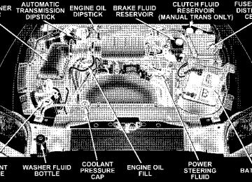
3.7L/4.7L ENGINE COMPARTMENT
ONBOARD DIAGNOSTIC SYSTEM — OBD II Your vehicle is equipped with a sophisticated onboard diagnostic system called OBD II. This system monitors the performance of the emissions, engine, and automatic transmission control systems. When these systems are operating properly, your vehicle will provide excellent performance and fuel economy, as well as engine emis- sions well within current government regulations. If any of these systems require service, the OBD II system will turn on the “Malfunction Indicator Light.” It will also store diagnostic codes and other information to assist your service technician in making repairs. Al- though your vehicle will usually be drivable and not need towing, see your dealer for service as soon as possible.
MAINTAINING YOUR VEHICLE 293
CAUTION!
• Prolonged driving with the “Malfunction Indica- tor Light” on could cause further damage to the emission control system. It could also affect fuel economy and driveability. The vehicle must be serviced before any emissions tests can be per- formed. • If the “Malfunction Indicator Light” is flashing while the engine is running, severe catalytic con- verter damage and power loss will soon occur. Immediate service is required.
Loose Fuel Filler Cap Message After fuel is added, the vehicle diagnostic system can determine if the fuel filler cap is loose, improperly installed, or damaged. A loose fuel filler cap message will be displayed in the instrument cluster. Tighten the gas
294 MAINTAINING YOUR VEHICLE
cap until a ⬙clicking⬙ sound is heard. This is an indication that the gas cap is properly tightened. Press the odometer reset button to turn the message off. If the problem persists, the message will appear the next time the vehicle is started. This might indicate a damaged cap. If the problem is detected twice in a row, the system will turn on the Malfunction Indicator Light (MIL). Resolving the problem will turn the MIL light off.
EMISSIONS INSPECTION AND MAINTENANCE PROGRAMS In some localities, it may be a legal requirement to pass an inspection of your vehicle’s emissions control system. Failure to pass could prevent vehicle registration.
For states which have an I/M (Inspection and Maintenance) requirement, this check verifies the following: the MIL (Malfunction Indicator Lamp)
is functioning and is not on when the engine is running, and that the OBD (On Board Diagnostic) system is ready for testing. Normally, the OBD system will be ready. The OBD system may not be ready if your vehicle was recently serviced, if you recently had a dead battery, or a battery replacement. If the OBD system is determined not ready for the I/M test, your vehicle may fail the test. Your vehicle has a simple ignition key actuated test which you can use prior to going to the test station. To check if your vehicle’s OBD system is ready, you must do the following: 1. Insert your ignition key into the ignition switch. 2. Turn the ignition to the ON position, but do not crank or start the engine. If you crank or start the engine, you will have to start this test over.
3. As soon as you turn your key to the ON position, you will see your MIL symbol come on as part of a normal bulb check. 4. Approximately 15 seconds later, one of two things will happen:
a. The MIL light will blink for approximately 5 sec- onds and then remain on until the first engine crank or the key is turned off. This means that your vehicle’s OBD system is not ready and you should not proceed to the I/M station. b. The MIL light will remain fully illuminated until the first engine crank or the key is turned off. This means that your vehicle’s OBD system is ready and you can proceed to the I/M station.
If your OBD system is not ready you should see your dealer or repair facility. If your vehicle was recently serviced or had a battery failure or replacement, you may
MAINTAINING YOUR VEHICLE 295
need to do nothing more than drive your vehicle as you normally would in order for your OBD system to update. A recheck with the above test routine may then indicate that the system is now ready. Regardless of whether your vehicle’s OBD system is ready or not ready, if the MIL symbol is illuminated during normal vehicle operation, you should have your vehicle serviced before going to the I/M station. The I/M station can fail your vehicle because the MIL symbol is on with the engine running.
REPLACEMENT PARTS Use of genuine Mopar威 parts for normal/scheduled maintenance and repairs is highly recommended to in- sure the designed performance. Damage or failures caused by the use of non-Mopar威 parts for maintenance and repairs will not be covered by the manufacturer’s warranty.
296 MAINTAINING YOUR VEHICLE
DEALER SERVICE Your dealer has the qualified service personnel, special tools and equipment to perform all service operations in an expert manner. Service manuals are available which include detailed service information for your vehicle. Refer to these manuals before attempting any procedure yourself. NOTE: systems can result against you.
Intentional tampering with emissions control in civil penalties being assessed
WARNING!
You can be badly injured working on or around a motor vehicle. Do only that service work for which you have the knowledge and the proper equipment. If you have any doubt about your ability to perform a service job, take your vehicle to a competent mechanic.
MAINTENANCE PROCEDURES The pages that follow contain the required maintenance services determined by the engineers who designed your vehicle. Besides the maintenance items for which there are fixed maintenance intervals, there are other items that should operate satisfactorily without periodic maintenance. However, if a malfunction of these items does occur, it
could adversely affect the engine or vehicle performance. These items should be inspected if a malfunction is observed or suspected. Engine Oil
Checking Engine Oil Level To assure proper lubrication of your vehicle’s engine, the engine oil must be maintained at the correct level. The best time to check the engine oil level is about 5 minutes after a fully warmed up engine is shut off or before starting the engine after it has sat overnight. Checking the oil while the vehicle is on level ground will improve the accuracy of the oil level readings. Always maintain the oil level within the SAFE zone on the dipstick. Adding one quart of oil when the reading is at the bottom of the SAFE zone will result in a reading at the top of the safe zone on these engines.
MAINTAINING YOUR VEHICLE 297
CAUTION!
Overfilling or underfilling the crankcase will cause oil aeration or loss of oil pressure. This could dam- age your engine.
298 MAINTAINING YOUR VEHICLE
Change Engine Oil Road conditions and your style of driving affect the interval at which your oil should be changed. Check the following to determine if ANY apply to you: • Day or night temperatures are below 32°F (0°C). • Stop and Go driving. • Extensive engine idling. • Driving in dusty conditions. • Short trips of less than 10 miles (16.2 km). • More than 50% of your driving is at sustained high • Trailer towing, Taxi, Police or delivery service (com- • Off-Road or desert operation.
speeds during hot weather, above 90°F (32°C).
mercial service).
• If equipped for and operating with E-85 (ethanol)
fuel.
If ANY of these apply to you then change your NOTE: engine oil every 3,000 miles (5 000 km) or 3 months, whichever comes first and follow schedule “B” of the ⬙Maintenance Schedules⬙ section of this manual. If NONE of these apply to you, then change your engine oil every 6,000 miles (10 000 km) or 6 months, whichever comes first and follow schedule ⬙A⬙ of the ⬙Maintenance Schedules⬙ section of this manual. NOTE: Under no circumstances should oil change in- tervals exceed 6,000 miles (10 000 km) or 6 months whichever comes first. 4x4 Models, If Used Primarily For Off-Road Operation Every 50 hours of use.
Dusty Conditions Driving through dust-laden air increases the problems of keeping abrasive materials out of the engine. Under these conditions, special attention should be given to the engine air cleaner. The crankcase ventilation system should also be checked periodically. Make sure that these units are always clean. This will tend to reduce to a minimum the amount of abrasive material that may enter the engine. Engine Oil Selection For best performance and maximum protection under all types of operating conditions, the manufacture only recommends engine oils that are API certified and meet the requirements of DaimlerChrysler Material Standard MS-6395.
MAINTAINING YOUR VEHICLE 299
American Petroleum Institute (API) Engine Oil Identification Symbol
This symbol means that the oil has been certified by the American Petroleum Institute (API). The manufacture only recommends API Certified engine oils.
Engine Oil Viscosity (SAE Grade) SAE 5W-20 engine oil is recommended for all operating temperatures. This engine oil improves low tempera- ture starting and vehicle fuel economy. Your engine oil filler cap also shows the recommended engine oil viscosity for your vehicle. For information on engine oil filler cap location, see the Engine Compartment illustration in this section.
300 MAINTAINING YOUR VEHICLE
Lubricants which do not have both, the engine oil certi- fication mark and the correct SAE viscosity grade num- ber should not be used. Synthetic Engine Oils You may use synthetic engine oils provided the recom- mended oil quality requirements are met, and the recom- mended maintenance intervals for oil and filter changes are followed. Materials Added to Engine Oils The manufacture strongly recommends against the addi- tion of any additives (other than leak detection dyes) to the engine oil. Engine oil is an engineered product and it’s performance may be impaired by supplemental ad- ditives. Disposing of Used Engine Oil And Oil Filters Care should be taken in disposing of used engine oil and oil filters from your vehicle. Used oil and oil filters, indiscriminately discarded, can present a problem to the
environment. Contact your dealer, service station, or governmental agency for advice on how and where used oil and oil filters can be safely discarded in your area. Engine Oil Filter The engine oil filter should be replaced at every engine oil change. Engine Oil Filter Selection The manufacturer’s engines have a full-flow type oil filter. Use a filter of this type for replacement. The quality of replacement filters varies considerably. Only high quality filters should be used to assure most efficient service. Mopar威 Engine Oil Filters are a high quality oil filter and are recommended.
Drive Belts — Check Condition and Tension Belt tension is controlled by means of an automatic tensioner. No belt tension adjustments are required. However, belt and belt tensioner condition should be inspected at the specified intervals, and replaced if re- quired. See your authorized dealer for service At the mileage indicated in the maintenance schedule, all belts and tensioner should be checked for condition. Improper belt tension can cause belt slippage and failure. Belts should be inspected for evidence of cuts, cracks, glazing, or frayed cords and replaced if there is indication of damage which could result in belt failure. Low gen- erator belt tension can cause battery failure. Also check belt routing to make sure there is no interfer- ence between the belts and other engine components.
MAINTAINING YOUR VEHICLE 301
Spark Plugs Spark plugs must fire properly to assure proper engine performance and emission control. The plugs installed in your vehicle should operate satisfactorily in normal service for the mileage indicated in the Maintenance Chart. New plugs should be installed at this mileage. The entire set should be replaced if there is any malfunction due to a faulty spark plug. Check the Vehicle Emissions Control Information label for the proper type of spark plug for your vehicle.
CAUTION!
When replacing plugs, do not overtighten. You could damage them and cause them to leak.
302 MAINTAINING YOUR VEHICLE
Engine Air Cleaner Filter Under normal driving conditions, replace the air filter at the intervals shown on Schedule “A”. If, however, you drive the vehicle frequently under dusty or severe con- ditions, the filter element should be inspected periodi- cally and replaced if necessary at the intervals shown on Schedule “B”.
WARNING!
The air cleaner can provide a measure of protection in the case of engine backfire. Do not remove the air cleaner unless such removal is necessary for repair or maintenance. Make sure that no one is near the engine compartment before starting the vehicle with the air cleaner removed. Failure to do so can result in serious personal injury.
Engine Fuel Filter A plugged fuel filter can cause stalling, limit the speed at which a vehicle can be driven or cause hard starting. Should an excessive amount of dirt accumulate in the fuel tank, frequent filter replacement may be necessary. Catalytic Converter The catalytic converter requires the use of unleaded fuel only. Leaded gasoline will destroy the effectiveness of the catalyst as an emission control device. Under normal operating conditions, the catalytic con- verter will not require maintenance. However, it is im- portant to keep the engine properly tuned to assure proper catalyst operation and prevent possible catalyst damage.
CAUTION!
Damage to the catalytic converter can result if your vehicle is not kept in proper operating condition. In the event of engine malfunction, particularly involv- ing engine misfire or other apparent loss of perfor- mance, have your vehicle serviced promptly. Contin- ued operation of your vehicle with a severe malfunction could cause the converter to overheat, resulting in possible damage to the converter and the vehicle.
NOTE: systems can result against you.
Intentional tampering with emissions control in civil penalties being assessed
MAINTAINING YOUR VEHICLE 303
WARNING!
A hot exhaust system can start a fire if you park over materials that can burn. Such materials might be grass or leaves coming into contact with your ex- haust system. Do not park or operate your vehicle in areas where your exhaust system can contact any- thing that can burn.
In unusual situations involving grossly malfunctioning engine operation, a scorching odor may indicate severe and abnormal catalyst overheating. If this occurs, the vehicle should be stopped, the engine shut off and the vehicle allowed to cool. Thereafter, service, including a tune-up to manufacturer’s specifications, should be ob- tained immediately.
304 MAINTAINING YOUR VEHICLE
To minimize the possibility of catalyst damage: • Do not shut off the engine or interrupt the ignition when the transmission is in gear and the vehicle is in motion. • Do not try to start engine by pushing or towing the • Do not idle the engine with any spark plug wires disconnected or removed, such as when diagnostic testing, or for prolonged periods during very rough idling or malfunctioning operating conditions.
vehicle.
Maintenance Free Battery The top of the maintenance free battery is permanently sealed. You will never have to add water, nor is periodic maintenance required.
WARNING!
• Battery fluid is a corrosive acid solution and can burn or even blind you. Don’t allow battery fluid to contact your eyes, skin or clothing. Don’t lean over a battery when attaching clamps. If acid splashes in eyes or on skin, flush the area imme- diately with large amounts of water. • Battery gas is flammable and explosive. Keep flame or sparks away from the battery. Don’t use a booster battery or any other booster source with an output greater than 12 volts. Don’t allow cable clamps to touch each other. • Battery posts, terminals and related accessories contain lead and lead compounds. Wash hands after handling.
CAUTION!
• It is essential when replacing the cables on the battery that the positive cable is attached to the positive post and the negative cable is attached to the negative post. Battery posts are marked (+) positive and negative (-) and identified on the battery case. • If a “fast charger” is used while battery is in vehicle, disconnect both vehicle battery cables before con- necting the charger to battery. Do not use a “fast charger” to provide starting voltage.
Air Conditioner Maintenance For best possible performance, your air conditioner should be checked and serviced by an Authorized Dealer at the start of each warm season. This service should include cleaning of the condenser fins and a performance test. Drive belt tension should also be checked at this time.
MAINTAINING YOUR VEHICLE 305
WARNING!
• Use only refrigerants and compressor lubricants approved by the manufacturer for your air condi- tioning system. Some unapproved refrigerants are flammable and can explode, injuring you. Other unapproved refrigerants or lubricants can cause the system to fail, requiring costly repairs. Refer to Section 3 of the Warranty Information book for further warranty information. • The air conditioning system contains refrigerant under high pressure. To avoid risk of personal injury or damage to the system, adding refrigerant or any repair requiring lines to be disconnected should be done by an experienced repairman.
306 MAINTAINING YOUR VEHICLE
Refrigerant Recovery and Recycling R-134a Air Conditioning Refrigerant is a hydrofluorocar- bon (HFC) that is endorsed by the Environmental Pro- tection Agency and is an ozone-saving product. How- ever, the manufacturer recommends that air conditioning service be performed by dealers or other service facilities using recovery and recycling equipment. Power Steering — Fluid Check Checking the power steering fluid level at a defined service interval is not required. The fluid should only be checked if a leak is suspected, abnormal noises are apparent, and/or the system is not functioning as antici- pated. Coordinate inspection efforts through a certified DaimlerChrysler Dealership.⬙
WARNING!
Fluid level should be checked on a level surface and with the engine off to prevent injury from moving parts and to insure accurate fluid level reading. Do not overfill. Use only manufacturers recommended power steering fluid.
If necessary, add fluid to restore to the proper indicated level. With a clean cloth, wipe any spilled fluid from all surfaces. Refer to Fluids, Lubricants, and Genuine Parts for correct fluid type. Front Suspension Ball Joints The ball joints and seals should be inspected whenever the vehicle is serviced for other reasons. Damaged seals should be replaced to prevent leakage or contamination of the grease.
Drive Shaft Constant Velocity Joints All four wheel drive models are equipped with four constant velocity joints. Periodic lubrication of these joints is not required. However, the joint boot should be inspected for external leakage or damage periodically. If external leakage or damage is evident, the joint boot and grease should be replaced immediately. Continued op- eration could result in failure of the joint due to water and dirt contamination of the grease. This would require complete replacement of the joint assembly. Refer to the Service Manual for the detailed replacement procedure. Body Lubrication Locks and all body pivot points, including such items as seat tracks, doors and hood hinges, should be lubricated periodically to assure quiet, easy operation and to protect against rust and wear. Prior to the application of any lubricant, the parts concerned should be wiped clean to remove dust and grit; after lubricating excess oil and grease should be removed. Particular attention should
MAINTAINING YOUR VEHICLE 307
also be given to hood latching components to insure proper function. When performing other underhood ser- vices, the hood latch, release mechanism and safety catch should be cleaned and lubricated. The external lock cylinders should be lubricated twice a year, preferably in the fall and spring. Apply a small amount of a high quality lubricant such as Mopar威 Lock Cylinder Lubricant directly into the lock cylinder. Windshield Wiper Blades The rubber edges of the wiper blades and the windshield should be cleaned periodically with a sponge or soft cloth and a mild nonabrasive cleaner. This will remove accu- mulations of salt or road film. Operation of the wipers on dry glass for long periods may cause deterioration of the wiper blades. Always use washer fluid when using the wipers to remove salt or dirt from a dry windshield.
308 MAINTAINING YOUR VEHICLE
Avoid using the wiper blades to remove frost or ice from the windshield. Keep the blade rubber out of contact with petroleum products such as engine oil, gasoline, etc. Windshield Washers The fluid reservoir should be checked for fluid level at regular intervals. When freezing weather is anticipated, flush out the water in the reservoir by operating the system. Fill the reservoir with windshield washer anti- freeze (not radiator antifreeze), and operate the system for a few seconds to flush out the residual water. To prevent freeze-up of your windshield washer system in cold weather, select a solution or mixture that meets or exceeds the temperature range of your climate. This rating information can be found on most washer fluid containers.
WARNING!
Commercially available windshield washer solvents are flammable. They could ignite and burn you. Care must be exercised when filling or working around the washer solution.
After the engine has warmed, operate the defroster for a few minutes to reduce the possibility of smearing or freezing the fluid on the cold windshield. Mopar威 All Weather Windshield Washer Solution used with water as directed on the container, aids cleaning action, reduces freezing point to avoid line clogging, and is not harmful to paint or trim.
Exhaust System The best protection against carbon monoxide entry into the vehicle body is a properly maintained engine exhaust system. Whenever a change is noticed in the sound of the exhaust system, when exhaust fumes can be detected inside the vehicle, or when the underside or rear of the vehicle is damaged, have a competent mechanic inspect the com- plete exhaust system and adjacent body areas for broken, damaged, deteriorated, or mispositioned parts. Open seams or loose connections could permit exhaust fumes to seep into the passenger compartment. In addition, inspect the exhaust system each time the vehicle is raised for lubrication or oil change. Replace as required.
MAINTAINING YOUR VEHICLE 309
WARNING!
Exhaust gases can injure or kill. They contain carbon monoxide (CO) which is colorless and odorless. Breathing it can make you unconscious and can eventually poison you. To avoid breathing CO, fol- low the preceding safety tips.
310 MAINTAINING YOUR VEHICLE
Cooling System
WARNING!
You or others can be badly burned by hot coolant or steam from your radiator. If you see or hear steam coming from under the hood, don’t open the hood until the radiator has had time to cool. Never try to open a cooling system pressure cap when the radia- tor is hot.
Engine Coolant Checks Check the engine coolant (antifreeze) protection every 12
months (before the onset of freezing weather, where applicable). If coolant is dirty or rusty in appearance, the system should be drained, flushed and refilled with fresh coolant. Check the front of the A/C condenser for anyaccumulation of bugs, leaves, etc. If dirty, clean by gently spraying water from a garden hose vertically down the face of the condenser. Check the coolant recovery bottle tubing for brittle rub- ber, cracking, tears, cuts and tightness of the connection at the bottle and radiator. Inspect the entire system for leaks. With the engine at normal operating temperature (but not running), check the cooling system pressure cap for proper vacuum sealing by draining a small amount of coolant from the radiator drain cock. If the cap is sealing properly, the engine coolant (antifreeze) will begin to drain from the coolant recovery bottle. DO NOT RE- MOVE THE COOLANT PRESSURE CAP WHEN THE COOLING SYSTEM IS HOT.
Cooling System — Drain, Flush and Refill At the intervals shown on the Maintenance Schedules, the system should be drained, flushed and refilled. If the solution is dirty or contains a considerable amount of sediment, clean and flush with a reliable cooling system cleaner. Follow with a thorough rinsing to remove all deposits and chemicals. Properly dispose of old antifreeze solution. Selection Of Coolant Use only the manufacturers recommended coolant, refer to Fluids, Lubricants and Genuine Parts for correct coolant type.
MAINTAINING YOUR VEHICLE 311
CAUTION!
Mixing of coolants other than specified HOAT en- gine coolants, may result in engine damage and may decrease corrosion protection. If a non-HOAT cool- ant is introduced into the cooling system in an emergency, it should be replaced with the specified coolant as soon as possible. Do not use plain water alone or alcohol base engine coolant (antifreeze) products. Do not use additional rust inhibitors or antirust products, as they may not be compatible with the radiator engine coolant and may plug the radiator. This vehicle has not been designed for use with Propylene Glycol based coolants. Use of Propylene Glycol based coolants is not recommended.
312 MAINTAINING YOUR VEHICLE
Adding Coolant Your vehicle has been built with an improved engine coolant that allows extended maintenance intervals. This coolant can be used up to 5 Years or 100,000 miles before replacement. To prevent reducing this extended mainte- nance period, it is important that you use the same coolant throughout the life of your vehicle. Please review these recommendations for using Hybrid Organic Addi- tive Technology (HOAT) coolant. When adding coolant, a minimum solution of 50% rec- ommended Mopar Antifreeze/ Coolant 5 Year/100,000
Mile Formula HOAT (Hybrid Organic Additive Technol- ogy), or equivalent, in water should be used. Use higher concentrations (not to exceed 70%) if temperatures below ⫺34°F (⫺37°C ) are anticipated. Use only high purity water such as distilled or deionized water when mixing the water/engine coolant solution.The use of lower quality water will reduce the amount of corrosion protection in the engine cooling system. Please note that it is the owner’s responsibility to main- tain the proper level of protection against freezing ac- cording to the temperatures occurring in the area where the vehicle is operated. NOTE: Mixing coolant types will decrease the life of the engine coolant and will require more frequent coolant changes. Cooling System Pressure Cap The cap must be fully tightened to prevent loss of coolant, and to insure that coolant will return to the radiator from the coolant recovery bottle. The cap should be inspected and cleaned if there is any accumulation of foreign material on the sealing surfaces.
WARNING!
• The warning words “DO NOT OPEN HOT” on the cooling system pressure cap are a safety pre- caution. Never add coolant when the engine is overheated. Do not loosen or remove the cap to cool an overheated engine. Heat causes pressure to build up in the cooling system. To prevent scalding or injury, do not remove the pressure cap while the system is hot or under pressure. • Do not use a pressure cap other than the one specified for your vehicle. Personal injury or engine damage may result.
Disposal of Used Engine Coolant Used ethylene glycol based engine coolant is a regulated substance requiring proper disposal. Check with your local authorities to determine the disposal rules for your community. To prevent ingestion by animals or children
MAINTAINING YOUR VEHICLE 313
do not store ethylene glycol based engine coolant in open containers or allow it to remain in puddles on the ground. If ingested by a child, contact a physician immediately. Clean up any ground spills immediately. Coolant Level The coolant bottle provides a quick visual method for determining that the coolant level is adequate. With the engine cold, the level of the coolant in the coolant recovery bottle should be between the ranges indicated on the bottle. The radiator normally remains completely full, so there is no need to remove the radiator cap unless checking for coolant freeze point or replacing coolant. Advise your service attendant of this. As long as the engine operating temperature is satisfactory, the coolant bottle need only be checked once a month.
314 MAINTAINING YOUR VEHICLE
When additional coolant is needed to maintain the proper level, it should be added to the coolant bottle. Do not overfill. Points To Remember NOTE: When the vehicle is stopped after a few miles (a few kilometers) of operation, you may observe vapor coming from the front of the engine compartment. This is normally a result of moisture from rain, snow, or high humidity accumulating on the radiator and being vapor- ized when the thermostat opens, allowing hot coolant to enter the radiator. If an examination of your engine compartment shows no evidence of radiator or hose leaks, the vehicle may be safely driven. The vapor will soon dissipate. • Do not overfill the coolant recovery bottle.
• Check coolant freeze point in the radiator and in the coolant recovery bottle. If antifreeze needs to be added, contents of coolant recovery bottle must also be protected against freezing. • If frequent coolant additions are required, or if the level in the coolant recovery bottle does not drop when the engine cools, the cooling system should be pres- sure tested for leaks. • Maintain coolant concentration at 50% HOAT engine coolant (minimum) and distilled water for proper corrosion protection of your engine which contains aluminum components. • Make sure that the radiator and coolant recovery bottle overflow hoses are not kinked or obstructed. • Keep the front of the radiator clean. If your vehicle is equipped with air conditioning, keep the front of the condenser clean, also.
• Do not change the thermostat for summer or winter operation. If replacement is ever necessary, install ONLY the correct type thermostat. Other designs may result in unsatisfactory coolant performance, poor gas mileage, and increased emissions.
Emission Related Components
Fuel System Hoses And Vapor/Vacuum Harnesses When the vehicle is serviced for scheduled maintenance, inspect surface of hoses and nylon tubing for evidence of heat and mechanical damage. Hard and brittle rubber, cracking, checking, tears, cuts, abrasions, and excessive swelling suggest deterioration of the rubber. Particular attention should be given to examining hose surfaces nearest to high heat sources, such as the exhaust mani- fold. Insure nylon tubing in these areas has not melted or collapsed.
MAINTAINING YOUR VEHICLE 315
Inspect all hose clamps and couplings to make sure they are secure and no leaks are present. You are urged to use only the manufacturer’s specified hoses and clamps, or their equivalent in material and specification, in any fuel system servicing. It is manda- tory to replace all clamps that have been loosened or removed during service. Care should be taken in install- ing new clamps to insure they are properly torqued. Positive Crankcase Ventilation (PCV) Valve Proper operation of the crankcase ventilation system requires that the PCV valve be free of sticking or plug- ging because of deposits. Deposits can accumulate in the PCV valve and passage with increasing mileage. Have the PCV valve, hoses, and passages checked for proper operation at the valve is plugged or sticking, replace with a new valve – Do not
the intervals specified.
If
316 MAINTAINING YOUR VEHICLE
attempt to clean the oil PCV valve! Check ventilating hose for indication of damage or plugging with deposits. Replace if necessary. Brake System
Power Disc Brakes (Front) Disc brakes do not require adjustment; however, several hard stops during the break-in period are recommended to seat the linings and wear off any foreign material. Brake Master Cylinders The fluid level in the master cylinders should be checked whenever the vehicle is serviced, or immediately if the brake system warning light is on. If necessary, add fluid to bring level to the full mark on the side of the reservoir of the brake master cylinder. Be sure to clean the top of the master cylinder area before removing the cap. With disc brakes, fluid level can be expected to fall as the brake
pads wear. Brake fluid level should be checked when pads are replaced. If the brake fluid level is abnormally low, check system for leaks. Refer to Fluids, Lubricants and Genuine Parts for correct fluid type.
WARNING!
Use of brake fluid that may have a lower initial boiling point, or is unidentified as to specifications, may result in sudden brake failure during hard prolonged braking. You could have an accident.
WARNING!
Overfilling the brake fluid reservoir can result in spilling brake fluid on hot engine parts and the brake fluid catching fire.
Use only brake fluid that has been in a tightly closed container to avoid contamination from foreign matter or moisture.
CAUTION!
Do not allow a petroleum-base fluid to contaminate the brake fluid. Seal damage may result.
Brake Linings Your vehicle is equipped with self-adjusting brakes. During normal driving, a few brake applications while
MAINTAINING YOUR VEHICLE 317
moving in reverse will maintain your brakes at the specified adjustment. Adjustment will continue until the brake linings are worn. To avoid brake failure, brake pull or damage to the rotors or drums, inspect the brake linings as specified in the maintenance schedule. If excessively worn, the brake linings must be replaced. Brake Hoses Inspection should be performed whenever the brake system is serviced or at intervals specified. Inspect hy- draulic brake hoses for surface cracking, scuffing or worn spots. If there is any evidence of cracking, scuffing, or worn spots, the hose should be replaced immediately! Eventual deterioration of the hose can take place with possible burst failure.
318 MAINTAINING YOUR VEHICLE
WARNING!
Worn brake hoses can burst and cause brake failure. You could have an accident. If you see any sign of cracking, scuffing, or worn spots, have the brake hoses replaced immediately.
Clutch Hydraulic System The clutch hydraulic system is a sealed maintenance free system. In the event of leakage or other malfunction, the system must be replaced. Manual Transmission
Fluid Level Check This fluid should be checked whenever other underhood services are performed. The fluid level is checked by removing the fill plug. If the level of the lubricant is more than 1/4⬙ (6.35 mm) below the bottom of the filler hole while the vehicle is level, enough lubricant should be
added to bring the level to the bottom of the filler hole. This fluid does not require periodic changing. However, if it becomes necessary to add or replace the fluid in these transmissions, refer to Fluids, Lubricants and Genuine Parts for correct fluid type. Automatic Transmission
Fluid Level Check Check the fluid level while the transmission is at normal operating temperature 180°F (82°C). This occurs after at least 15 miles (24 km) of driving. At normal operating temperature the fluid cannot be held comfortably be- tween the fingertips. To check the automatic transmission fluid level properly, the following procedure must be used: 1. Operate the engine at idle speed and normal operating temperature. 2. The vehicle must be on level ground.
3. Fully apply the parking brake and press the brake pedal. 4. Place the gear selector momentarily in each gear position ending with the lever in P (Park). 5. Remove the dipstick, wipe it clean and reinsert it until seated. 6. Remove the dipstick again and note the fluid level on both sides. The fluid level should be between the “HOT” (upper) reference holes on the dipstick at normal operat- ing temperature. Verify that solid coating of oil is seen on both sides of the dipstick. If the fluid is low, add as required into the dipstick tube. Do not overfill. After adding any quantity of oil through the oil fill tube, wait a minimum of two (2) minutes for the oil to fully drain into the transmission before rechecking the fluid level. If it is necessary to check the transmission below NOTE: the operating temperature, the fluid level should be
MAINTAINING YOUR VEHICLE 319
between the two “COLD” (lower) holes on the dipstick with the fluid at approximately 70°F ( 21°C) (room temperature). If the fluid level is correctly established at room temperature, it should be between the “HOT” (upper) reference holes when the transmission reaches 180°F ( 82°C). Remember it is best to check the level at the normal operating temperature.
CAUTION!
Be aware that if the fluid temperature is below 50°F (10°C) it may not register on the dipstick. Do not add fluid until the temperature is elevated enough to produce an accurate reading.
7. Check for leaks. Release parking brake. To prevent dirt and water from entering the transmission after checking or replenishing fluid, make certain that the
320 MAINTAINING YOUR VEHICLE
dipstick cap is properly reseated. It is normal for the dipstick cap to spring back slightly from its fully seated position, as long as its seal remains engaged in the dipstick tube. Automatic Transmission Fluid And Filter Change To obtain best performance and long life for automatic transmissions, the manufacturer recommends that they be given regular maintenance service by an Authorized Dodge Dealer or Service Center. It is important that the transmission fluid be maintained at the correct level and that it be drained and refilled as specified. Follow the proper Maintenance Schedule for your type of driving. It is important that proper lubricant is used in the transmission. Refer to Fluids, Lubricants and Genuine Parts for correct fluid type. It is important that the transmission fluid be maintained at the prescribed level using the recommended fluid.
CAUTION!
Using a transmission fluid other than the manufac- turers recommended fluid may cause deterioration in transmission shift quality and/or torque converter shudder. Using a transmission fluid other than the manufacturers recommended fluid will result in more frequent fluid and filter changes. Refer to Fluids, Lubricants and Genuine Parts for correct fluid type.
Special Additives The manufacturer strongly recommends against the ad- dition of any additives to the transmission. Exception to this policy is the use of special dyes to aid in detecting fluid leaks. The use of transmission sealers should be avoided, since they may adversely affect seals.
Transfer Case Inspect the transfer case for fluid leaks. If a fluid leak is evident the transfer case fluid level may be low. Have the transfer case serviced immediately.
CAUTION!
Damage may result from operation of the vehicle with low transfer case fluid.
The transfer case fluid should be drained and refilled at the intervals specified. Lubricant Selection Refer to Fluids, Lubricants and Genuine Parts for correct fluid type.
MAINTAINING YOUR VEHICLE 321
Axles Refer to Fluids, Lubricants and Genuine Parts for correct fluid type. The manufacturer does not recommend regularly sched- uled oil changes for axles in vehicles whose operation is classified as normal truck service. NOTE: The presence of water in the gear lubricant will result in corrosion and possible failure of differential components. Operation of the vehicle in water, as may be encountered in some off-highway types of service, will require draining and refilling the axle to avoid damage. Rear Axle Rear Axle Limited-slip differentials require the use of Mopar limited-slip additive. Refer to Recommended Flu- ids, Lubricants and Genuine Parts for correct fluid type. This should be added to the gear lubricant whenever a fluid change is made, when equipped with limited-slip
322 MAINTAINING YOUR VEHICLE
differential. Rear axle fluid level should be 1/4⬙ (6.4mm) below filler plug for 8 1/4”, and 9 1/4⬙ axles. Front Axle Front Axle fluid level should be at the bottom of the fill plug. Selection of Lubricating Grease The National Lubricating Grease Institute (NLGI) has developed a symbol (Certification Mark) to aid the vehicle owner in the proper selection of grease for chassis components. This symbol, an example shown below, is located on the grease container and identifies the appli- cation and quality of the grease.
are
There two groups identified, those for wheel bearings (Letter “G”) and those for chassis (Letter “L”) lubrication. Perfor- mance categories within these groups result in dual letter for each group. The letter des- ignations shown in the ex- ample the highest quality level available and when combined as shown can be used for chassis lubrication. Use only those greases that have the NLGI symbol on the container along with the proper quality level for your application.
designations
are
Appearance Care and Protection from Corrosion
Protection of Body and Paint from Corrosion Vehicle body care requirements vary according to geo- graphic locations and usage. Chemicals that make roads passable in snow and ice, and those that are sprayed on trees and road surfaces during other seasons, are highly corrosive to the metal in your vehicle. Outside parking, which exposes your vehicle to airborne contaminants, road surfaces on which the vehicle is operated, extreme hot or cold weather and other extreme conditions will have an adverse effect on paint, metal trim, and under- body protection. The following maintenance recommendations will enable you to obtain maximum benefit from the corrosion resistance built into your vehicle. What Causes Corrosion? Corrosion is the result of deterioration or removal of paint and protective coatings from your vehicle.
MAINTAINING YOUR VEHICLE 323
The most common causes are: • Road salt, dirt and moisture accumulation. • Stone and gravel impact. • Insects, tree sap and tar. • Salt in the air near seacoast localities. • Atmospheric fallout/industrial pollutants. Washing • Wash your vehicle regularly. Always wash your ve- hicle in the shade using a mild car wash soap, and rinse the panels completely with clear water. • If insects, tar or other similar deposits have accumu- • Use Mopar威 auto polish to remove road film and stains and to polish your vehicle. Take care never to scratch the paint.
lated on your vehicle, wash it as soon as possible.
324 MAINTAINING YOUR VEHICLE
• Avoid using abrasive compounds and power buffing that may diminish the gloss or thin out the paint finish.
CAUTION!
Do not use abrasive or strong cleaning materials such as steel wool or scouring powder, which will scratch metal and painted surfaces.
Special Care • If you drive on salted or dusty roads or if you drive near the ocean, hose off the undercarriage at least once a month. • It is important that the drain holes in the lower edges
of the doors, rocker panels be kept clear and open.
• If you detect any stone chips or scratches in the paint, touch them up immediately. The cost of such repairs is considered the responsibility of the owner. • If your vehicle is damaged due to an accident or similar cause which destroys the paint and protective coating have your vehicle repaired as soon as possible. The cost of such repairs is considered the responsibil- ity of the owner. • If you carry special cargo such as chemicals, fertilizers, de-icer salt, etc., be sure that such materials are well packaged and sealed. • If a lot of driving is done on gravel roads, consider • Use Mopar威 touch up paint on scratches as soon as possible. Your dealer has touch up paint to match the color of your vehicle.
mud or stone shields behind each wheel.
Wheel and Wheel Trim Care All wheels and wheel trim, especially aluminum and chrome plated wheels should be cleaned regularly with a mild soap and water to prevent corrosion. To remove heavy soil, use Mopar Wheel Cleaner or select a nonabra- sive, non-acidic cleaner. Do not use scouring pads, steel wool, a bristle brush or metal polishes. Only Mopar cleaners are recommended. Do not use oven cleaner. Avoid automatic car washes that use acidic solutions or harsh brushes that may damage the wheels’ protective finish. YES Essentials威 Fabric Cleaning Procedure – If Equipped YES Essentials威 seats may be cleaned in the following manner: • Remove as much of the stain as possible by blotting • Blot any remaining stain with a clean, damp towel.
with a clean, dry towel.
MAINTAINING YOUR VEHICLE 325
• For tough stains, apply Mopar Total Clean or a mild soap solution to a clean, damp cloth and remove stain. Use a fresh, damp towel to remove soap residue. • For grease stains, apply Mopar Multi-purpose cleaner to a clean, damp cloth and remove stain. Use a fresh, damp towel to remove soap residue. • Do not use any solvents or protectants on Yes Essen-
tials products.
Interior Care Use Mopar威 Fabric Cleaner to clean fabric upholstery and carpeting. Use Mopar威 Vinyl Cleaner to clean vinyl upholstery and trim. Mopar威 Total Clean is specifically recommended for leather upholstery.
326 MAINTAINING YOUR VEHICLE
Your leather upholstery can be best preserved by regular cleaning with a damp soft cloth. Small particles of dirt can act as an abrasive and damage the leather upholstery and should be removed promptly with a damp cloth. Stubborn soils can be removed easily with a soft cloth and Mopar威 Total Clean. Care should be taken to avoid soaking your leather upholstery with any liquid. Please do not use polishes, oils, cleaning fluids, solvents, deter- gents, or ammonia based cleaners to clean your leather upholstery. Application of a leather conditioner is not required to maintain the original condition.
WARNING!
Do not use volatile solvents for cleaning purposes. Many are potentially flammable, and if used in closed areas they may cause respiratory harm.
Glass Surfaces All glass surfaces should be cleaned on a regular basis with any commercial household-type glass cleaner. Never use an abrasive type cleaner. Use caution when cleaning inside rear windows equipped with electric defrosters or windshields equipped with a windshield wiper de-icer. Do not use scrapers or other sharp instru- ments which may scratch the elements. When cleaning the rear view mirror, spray cleaner on the towel or rag that you are using. Do not spray cleaner directly on the mirror. Cleaning Plastic Instrument Cluster Lenses The lenses in front of the instruments in this vehicle are molded in clear plastic. When cleaning the lenses, care must be taken to avoid scratching the plastic.
1. Clean with a wet soft rag. A mild soap solution may be used, but do not use high alcohol content or abrasive cleaners. If soap is used, wipe clean with a clean damp rag. 2. Dry with a soft tissue. Seat Belt Maintenance Do not bleach, dye or clean the belts with chemical solvents or abrasive cleaners. This will weaken the fabric. Sun damage will also weaken the fabric. If the belts need cleaning, use a mild soap solution or lukewarm water. Do not remove the belts from the car to wash them. Replace the belts if they appear frayed or worn or if the buckles do not work properly.
MAINTAINING YOUR VEHICLE 327
FUSES (POWER DISTRIBUTION CENTER) Your vehicle is equipped with an electrical power distri- bution center located on the left side of the engine compartment.
Power Distribution Center
328 MAINTAINING YOUR VEHICLE
These power distribution centers house new plug-in “Cartridge” fuses which replace all the in-line fusible links previously used. The power distribution centers also contain “Mini”fuses and plug-in “ISO” relays. These fuses and relays can be obtained from your dealer. Cavity Cartridge
Description
Mini Fuse
Fuse
Spare Ignition Accessory (ACC) Electric Brake
40 Amp Green 30 Amp Pink 50 Amp Red 40 Amp Green
Power Seat
Ignition Run Only
20 Amp Yellow
Ignition Off Draw (IOD) Cabin Compartment Node (CCN), Radio
Cavity Cartridge
Fuse
10
1112
13
14
15
Mini Fuse 10 Amp Red
10 Amp Red 10 Amp Red
10 Amp Red 15 Amp Blue 15 Amp Blue 20 Amp Yellow 25 Amp Natural
Description
Powertrain Control Mod- ule (PCM)/Fuel/ RAD/AC Coils Cabin Compartment Node (CCN)/Mirror/4x4
Airbag System #3Spare AC Clutch
T Tow Lt Stop/Turn
Trailer Tow Rt Stop/ Turn Ignition Off Draw (IOD) #2
Trans/Powertrain Con- trol Module (PCM)Cavity Cartridge 16
Fuse
17
18
19
20
21
22
23
Mini Fuse 20 Amp Yellow 20 Amp Yellow 20 Amp Yellow 15 Amp Blue 20 Amp Yellow
25 Amp Natural 20 Amp Yellow 20 Amp Yellow
Description
Horn
ABS Feed (Valves)
Fuel Pump
Center High Mounted Stop Lamp (CHMSL) Cabin Compartment Node (CCN) Door Locks/Brake Transmis- sion Shift Interlock (BTSI) Audio Amp
Power Outlet (Switch- able) Fog Lamps
MAINTAINING YOUR VEHICLE 329
Mini Fuse 20 Amp Yellow 15 Amp Blue
10 Amp Red 20 Amp Yellow 20 Amp Yellow
Description
Powertrain Control Mod- ule (PCM) B+ Cabin Compartment Node (CCN) Illumina- tion Spare Power Mirror
Power Outlet
Front Control Module (FCM) 4 (Wipers) Spare Spare Front Control Module (FCM) 1 (Ext. Lights # 1) Auto Shut Down (ASD)
Cavity Cartridge 24
Fuse
25
26
2728
29
30
31
3233
30 Amp Pink 30 Amp Pink
330 MAINTAINING YOUR VEHICLE
Cavity Cartridge 34
Fuse