- 2010 Dodge Dakota Owners Manuals
- Dodge Dakota Owners Manuals
- 2008 Dodge Dakota Owners Manuals
- Dodge Dakota Owners Manuals
- 2006 Dodge Dakota Owners Manuals
- Dodge Dakota Owners Manuals
- 2009 Dodge Dakota Owners Manuals
- Dodge Dakota Owners Manuals
- 2004 Dodge Dakota Owners Manuals
- Dodge Dakota Owners Manuals
- 2011 Dodge Dakota Owners Manuals
- Dodge Dakota Owners Manuals
- 2005 Dodge Dakota Owners Manuals
- Dodge Dakota Owners Manuals
- 2007 Dodge Dakota Owners Manuals
- Dodge Dakota Owners Manuals
- Download PDF Manual
-
fuel in case the engine is flooded.
CAUTION!
To prevent damage to the starter, do not crank the engine for more than 15 seconds at a time. Wait 10 to 15 seconds before trying again.
WARNING!
Never pour fuel or other flammable liquids into the throttle body air inlet opening in an attempt to start the vehicle. This could result in a flash fire causing serious personal injury.
WARNING!
Do not attempt to push or tow your vehicle to get it started. Vehicles equipped with an automatic trans- mission cannot be started this way. Unburned fuel could enter the catalytic converter and once the engine has started, ignite and damage the converter and vehicle. If the vehicle has a discharged battery, booster cables may be used to obtain a start from a booster battery or the battery in another vehicle. This type of start can be dangerous if done improperly. See section 6 of this manual for the proper jump starting procedures and follow them carefully.
If the engine has been flooded, it may start to run, but not have enough power to continue running when the key is
STARTING AND OPERATING 189
released. If this occurs, continue cranking with the accel- erator pedal pushed all the way to the floor. Release the accelerator pedal and the key once the engine is running smoothly. If the engine shows no sign of starting after two 15
second periods of cranking with the accelerator pedal held to the floor, the normal starting procedure should be repeated. After Starting The idle speed is automatically controlled and will de- crease as the engine warms up.Engine Block Heater — If Equipped The engine block heater warms engine coolant and permits quicker starts in cold weather. Connect the cord to a standard 110-115 volt AC electrical outlet with a grounded, three wire extension cord.
190 STARTING AND OPERATING
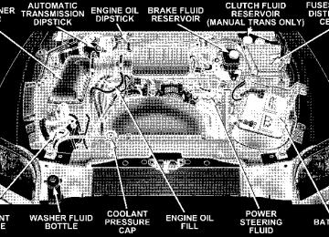
The engine block heater cord is located at the right front of the engine compartment for all engine applications.
AUTOMATIC TRANSMISSION
WARNING!
Remember to disconnect the cord before driving. Damage to the 110-115 volt electrical cord could cause electrocution.
CAUTION!
a complete stop.
Damage to the transmission may occur if the follow- ing precautions are not observed: • Shift into PARK only after the vehicle has come to • Shift into or out of REVERSE only after the vehicle has come to a complete stop and the engine is at idle speed. • Do not shift from REVERSE, PARK, or NEUTRAL into any forward gear when the engine is above idle speed. • Before shifting into any gear, make sure your foot
is firmly on the brake pedal.
WARNING!
It is dangerous to shift the selector lever out of “P” or “N” if the engine speed is higher than idle speed. If your foot is not firmly on the brake pedal, the vehicle could accelerate quickly forward or in re- verse. You could lose control of the vehicle and hit someone or something. Only shift into gear when the engine is idling normally and when your right foot is firmly on the brake pedal.
Brake/Transmission Interlock System This system prevents you from moving the gear shift out of Park and into any gear unless the brake pedal is pressed. This system is active only while the ignition switch is in the ON position. Always depress the brake pedal first, before moving the gear selector out of PARK.
STARTING AND OPERATING 191
Automatic Transmission The electronic PRNDL on the instrument cluster indicates the transmission gear selected. The selector lever is mounted on the right side of the steering column. To drive, move the selector lever from Park or Neutral to the desired drive position. Pull selector lever toward you when shifting into Reverse, Second, First or Park, or when shifting out of Park. Gear Ranges DO NOT race the engine when shifting from Park or Neutral position into another gear range. “P” Park Supplements parking brake by locking the transmission. Engine can be started in this range. Never use Park while vehicle is in motion. Apply parking brake when leaving vehicle in this range. Always apply parking brake first, then place selector in Park position.
192 STARTING AND OPERATING
WARNING!
WARNING!
Your vehicle could move and injure you and others if it is not completely in P (Park). Check by trying to move the gearshift lever back and forth without first pulling the lever toward you, after you have set it in P (Park). Make sure it is in Park before leaving the vehicle.
WARNING!
Never use Park position on an automatic transmis- sion as a substitute for the parking brake. Always apply parking brake fully when parked to guard against vehicle movement and possible injury or damage.
It is dangerous to shift the selector lever out of “P” or “N” if the engine speed is higher than idle speed. If your foot is not firmly on the brake pedal, the vehicle could accelerate quickly forward or in re- verse. You could lose control of the vehicle and hit someone or something. Only shift into gear when the engine is idling normally and when your right foot is firmly on the brake pedal.
“R” Reverse Use this range only after the vehicle has come to a complete stop. “N” Neutral Shift to Neutral when vehicle is standing for prolonged periods with engine running. Engine may be started in this range. Set the parking brake if you must leave the vehicle. “D” Drive For most city and highway driving. “2” Second For driving slowly in heavy city traffic or on mountain roads where more precise speed control is desirable. Use it also when climbing long grades, and for engine brak- ing when descending moderately steep grades. To pre- vent excessive engine speed do not exceed 45 miles per hour (72 km/h) in this range.
STARTING AND OPERATING 193
“1” First For driving up very steep hills and for engine braking at low speeds 25 mph (40 km/h) or less when going down hill. To prevent excessive engine speed do not exceed 25
mph (40 km/h) in this range. Overdrive Operation The overdrive automatic transmission contains an elec- tronically controlled fourth and fifth (if equipped) speed (Overdrive). The transmission will automatically shift from Drive to Overdrive if the following conditions are present: • the transmission selector is in Drive; • the engine coolant has reached normal operating tem- • vehicle speed is above approximately 30 mph (48
• the “TOW/HAUL” switch has not been activated;perature;
km/h);
194 STARTING AND OPERATING
• transmission has reached normal operating tempera-
ture. If the vehicle is started in extremely cold tem- NOTE: peratures, the transmission may not shift into Overdrive and will automatically select the most desirable gear for operation at this temperature. Normal operation will resume when the transmission fluid temperature has risen to a suitable level. Refer also to the Note under torque converter clutch, later in this section. If the transmission temperature gets extremely hot, the transmission will automatically select the most desirable gear for operation at this temperature. If the transmission temperature becomes hot enough the TRANS TEMP light may illuminate and the transmission may downshift out of Overdrive until the transmission cools down. After cooldown, the transmission will resume normal opera- tion.
The transmission will downshift from Overdrive to Drive if the accelerator pedal is fully depressed at vehicle speeds above approximately 35 mph (56 km/h). When To Use “TOW/HAUL” Mode
When driving in hilly areas, towing a trailer, carrying a heavy load, etc., and frequent transmission shifting oc- curs, press the “TOW/HAUL” button. This will improve
5th gear
performance and reduce the potential for transmission overheating or failure due to excessive shifting. When operating in “TOW/HAUL” mode, (if equipped) is disabled and 2-3 and 3-4 shift patterns are modified. Shifts into Overdrive (4th gear) are allowed during steady cruise (for improved fuel economy) and automatic closed-throttle downshifts to 3rd gear (for improved braking) will occur during steady braking. The “TOW/HAUL” light will illuminate in the instru- ment cluster to indicate when the switch has been activated. Pressing the switch a second time restores normal operation. If the “TOW/HAUL” mode is desired, the button must be pressed each time the engine is started. Torque Converter Clutch A feature designed to improve fuel economy is included in all automatic transmissions. A clutch within the torque converter engages automatically at a calibrated speed at
STARTING AND OPERATING 195
the
light throttle. It engages at higher speeds under heavier acceleration. This may result in a slightly different feeling or response during normal operation in high gear. When the vehicle speed drops below a calibrated speed, or during acceleration, clutch automatically and smoothly disengages. The feature is operational in Over- drive and in Drive. NOTE: The torque converter clutch will not engage until the transmission fluid and engine coolant are warm [usually after 1-3 miles (1.6 - 4.8 km) of driving]. Because the engine speed is higher when the torque converter clutch is not engaged, it may seem as if the transmission is not shifting into Overdrive when cold. This is normal. Pressing the⬙TOW/HAUL⬙ button, when the transmis- sion is sufficiently warm, will demonstrate that the transmission is able to shift into and out of Overdrive. If the vehicle has not been driven in several NOTE: days, the first few seconds of operation after shifting the
196 STARTING AND OPERATING
transmission into gear may seem sluggish. This is due to the fluid partially draining from the torque converter into the transmission. This condition is normal and will not cause damage to the transmission. The torque converter will refill within five seconds of shifting from Park into any other gear position.
MANUAL TRANSMISSION
WARNING!
You or others could be injured if you leave the vehicle unattended without having the parking brake fully applied. The parking brake should al- ways be applied when the driver is not in the vehicle, especially on an incline.
This model is equipped with a clutch interlocking igni- tion system. The clutch pedal must be fully depressed to start the vehicle. Fully depress the clutch pedal before shifting gears. As you release the clutch pedal, lightly depress the accelera- tor pedal. When launching a stationary vehicle, keep the engine speed low until the clutch is fully engaged. NOTE: Always launch in first gear. Damage to the clutch can result from launching in 2nd gear or 3rd gear. Use each gear in numerical order, do not skip a gear. When shifting from 5th to 6th gear, do not apply exces- sive knob load toward the Reverse gear gate, as you may overpower Reverse crash-through load and unintention- ally clash into Reverse gear. Also, when shifting from 6th to 5th gear, excessive knob load toward the Reverse gear gate will result in blocking of the shift.
STARTING AND OPERATING 197
Higher upshift speeds may be used to obtain a desired acceleration rate.
6 Speed Manual Transmission Shift Speed in mph
En- gine Model Axle
3.7L ALL
4.7L
All
3.21
3.553.21
3.55(km/h) 1 to
Accel- eration Rate
ACCEL
CRUISE
ACCEL
CRUISE
15
(24) 10
(16)15
(24)2 to
24
(39) 19
(31)25
(40)3 to
34
(55) 27
(44)40
(65)4 to
47
(76) 37
(60)45
(72)5 to
56
(90) 41
(66)50
(81)To shift into Reverse, come to a complete stop. Depress the clutch and pause briefly to allow the gear train to stop. Reverse has a ⬙crash-through⬙ lockout feature. In order to get into the reverse gate you should start in neutral 3/4 and move rapidly into the reverse gate in one swift motion. If you move slowly toward reverse you will encounter a very high load which makes it difficult to enter the gate. Never drive with your foot resting on the clutch pedal, or attempt to hold the vehicle on a hill with the clutch pedal partially engaged, as this will cause abnormal wear on the clutch. Recommended Shift Speeds To use your manual transmission for fuel economy it should be upshifted as listed below. Shift at the vehicle speeds listed for acceleration. Earlier upshifts during cruise conditions (relatively steady speeds) will result in increased fuel economy, and may be used as indicated.
198 STARTING AND OPERATING
Downshifting Moving from a high gear down to a lower gear is recommended to preserve brakes when driving down steep hills. In addition, downshifting at the right time provides better acceleration when you desire to resume speed. For acceleration at speeds less than 20 mph (30
km/h), 2nd gear is recommended.1st
Maximum Recommended Downshifting Speeds Gear Selec- tion Maxi- mum Speed
(120
km/h)20 mph
35 mph
55 mph
75 mph
km/h)
km/h)
km/h)
2nd
3rd
4th
(32
(56
(88
5th
85 mph
(135
km/h)CAUTION!
CAUTION!
When descending a hill, be very careful to downshift one gear at a time to prevent overspeeding the engine which can cause valve damage.
Failure to follow the recommended downshifting speeds may cause the engine to over speed and / or damage the clutch disc even if the clutch pedal is depressed.
To prevent clutch and transmission damage, your vehicle should be downshifted at speeds no greater than those listed in the Maximum Recommended Downshifting Speed chart.
FOUR-WHEEL DRIVE OPERATION
NV233/243 GII Transfer Case Operating Information/Precautions The NV233/243 is an electric shift transfer case and is operated by the 4WD Control Switch (Transfer Case Switch), which is located on the instrument panel. The NV233/243 transfer case provides 4 mode positions: 2 (rear) wheel drive high range, 4 wheel drive high range, 4 wheel drive low range, and neutral. The NV233/243 transfer case is designed to be driven in the 2 wheel drive position (2WD) for normal street and highway conditions (dry hard surfaced roads). When additional traction is required, the transfer case 4WD LOCK and 4WD LOW positions can be used to lock the front and rear driveshafts together and force the front and rear wheels to rotate at the same speed. This is accomplished by rotating the 4WD Control Switch to the
STARTING AND OPERATING 199
desired position - see Shifting Procedure section for specific shifting instructions. The 4WD LOCK and 4WD LOW positions are designed for loose or slippery road surfaces only. Driving in the 4WD LOCK and 4WD LOW positions on dry hard-surfaced roads may cause in- creased tire wear and damage to the driveline compo- nents. The transfer case Neutral (N) position is selected by depressing the recessed button located on the lower left hand corner of the 4WD Control Switch. NOTE: The transfer case Neutral (N) position is to be used for recreational towing only. See Recreational Tow- ing section for specific procedures on shifting into and out of Neutral (N). Transfer Case Position Indicator Lights Transfer case position indicator lights are located on the instrument cluster. If there is no indicator light on or flashing, the transfer case position is two-wheel drive
200 STARTING AND OPERATING
(2WD). If the indicator light is on, the desired position (4WD LOCK and 4WD LOW) has been obtained. If One or More Shift Requirements are not Met: 1. An indicator light will flash. 2. The transfer case will not shift. NOTE: Before retrying a selection, make certain that all the necessary requirements for selecting a new transfer case position have been met. To retry the selection, turn the control knob back to the current position, wait five (5) seconds, and retry selection. To find the shift require- ments, refer to the ⬙Shifting Procedure⬙ for your transfer case, located in this section of the owner’s manual. The “SVC 4WD” warning light monitors the electric shift 4WD system. If this light remains on after engine start up or illuminates during driving, it means that the 4WD system is not functioning properly and that service is required.
WARNING!
Always engage the parking brake when powering down the vehicle if the ⴖSVC 4WDⴖ light is illumi- nated. Not engaging the parking brake may allow the vehicle to roll, which may cause personal injury.
NOTE: Do not attempt to make a shift while only the front or rear wheels are spinning. The NV233/243 trans- fer case is not equipped with a synchronizer and there- fore the front and rear driveshaft speeds must be equal for the shift to take place. Shifting while only the front or rear wheels are spinning can cause damage to the trans- fer case. When operating your vehicle in 4WD LOW, the engine speed is approximately three times that of the 2WD or
4WD LOCK positions at a given road speed. Take care not to overspeed the engine and do not exceed 25 mph (40 km/h). Proper operation of 4 wheel drive vehicles depends on tires of equal size, type and circumference on each wheel. Any difference in tire size can cause damage to the transfer case. Because 4 wheel drive provides improved traction, there is a tendency to exceed safe turning and stopping speeds. Do not go faster than road conditions permit.
STARTING AND OPERATING 201
WARNING!
You or others could be injured if you leave the vehicle unattended with the transfer case in the Neutral (N) position without first fully engaging the parking brake. The transfer case Neutral (N) position disengages both the front and rear driveshafts from the powertrain and will allow the vehicle to move regardless of the transmission position. The parking brake should always be applied when the driver is not in the vehicle.
For additional information on the appropriate use of each transfer case mode position see the information below: 2WD Rear Wheel Drive High Range - Normal street and highway driving. Dry hard surfaced roads.
202 STARTING AND OPERATING
4WD LOCK 4 Wheel Drive Lock (4WD LOCK) Range - Locks the front and rear driveshafts together. Forces the front and rear wheels to rotate at the same speed. Additional traction for loose or slippery road surfaces only. 4WD LOW 4 Wheel Drive Low (4WD LOW) Range - Low speed 4
wheel drive. Locks the front and rear driveshafts to- gether. Forces the front and rear wheels to rotate at the same speed. Additional traction and maximum pulling power for loose or slippery road surfaces only. Do not exceed 25 mph (40 km/h). Neutral - Disengages both the front and rear driveshafts from the powertrain. To be used for flat towing behind another vehicle. See Recreational Towing for more infor- mation.Shifting Procedure - NV233/243 Transfer Case
If any of the requirements to select a new NOTE: transfer case position have not been met, the transfer case will not shift, the indicator light for the previous position will remain ON, and the newly selected position indica- tor light will continue to flash until all the requirements for the selected position have been met. To retry a shift:
return the control knob back to the original position, make certain all shift requirements have been met, wait five (5) seconds and try the shift again. 2WD to 4WD LOCK or 4WD LOCK to 2WD Rotate the 4WD Control Switch to the desired position. Shifts between 2WD and 4WD LOCK can be done with the vehicle stopped or in motion. With the vehicle in motion, the transfer case will engage / disengage faster if you momentarily release the accelerator pedal after turn- ing the control switch. If the vehicle is stopped, the ignition key must be in the ON position with the engine either RUNNING or OFF. This shift cannot be completed if the key is in the accessory position. NOTE: On vehicles equipped with Anti-Lock Brake Systems, the 4x4 system will not allow shifts between 2WD/ 4WD LOCK if the rear wheels are spinning (no traction). In this situation the selected position indicator light will flash and the original position indicator light
STARTING AND OPERATING 203
will remain ON. At this time, reduce speed and stop spinning the wheels to complete the shift. There may be a delay up to 10 seconds for the shift to complete after the wheels have stopped spinning. 4WD LOCK to 4WD LOW or 4WD LOW to 4WD LOCK NOTE: When shifting into or out of 4WD LOW, some gear noise may be heard. This noise is normal and is not detrimental to the vehicle or occupants. Shifting can be performed with the vehicle rolling 2-3
mph (3-5 km/h) or completely stopped. USE EITHER OF THE FOLLOWING PROCEDURES: Preferred Procedure 1. With engine RUNNING, slow vehicle to 2-3 mph (3-5
km/h).204 STARTING AND OPERATING
2. Shift the transmission into NEUTRAL (depress clutch on manual transmissions). 3. While still rolling, rotate the transfer case control switch to the desired position. 4. After the desired position indicator light is ON (not flashing), shift transmission back into gear (release clutch on manual transmissions). Alternate Procedure 1. Bring the vehicle to complete stop. 2. With the key ON and the engine either OFF or RUNNING, shift the transmission into NEUTRAL (de- press clutch on manual transmissions). 3. Rotate the transfer case control switch to the desired position.
4. After the desired position indicator light is ON (not flashing), shift transmission back into gear (release clutch on manual transmissions). If steps 1 or 2 of either the Preferred or Alternate NOTE: Procedure are not satisfied prior to attempting the shift or if they no longer are being met while the shift attempt is in process, then the indicator light will flash and the current transfer case position will be maintained. To retry the selection, turn the control knob back to the current position, wait five (5) seconds, and retry shift. NOTE: The ignition key must be ON for a shift to take place and for the position indicator lights to be operable. If the key is not ON then the shift will not take place and no position indicator lights will be on or flashing.
NV 244 Generation II Transfer Case Operating Information / Precautions The NV 244 Generation II is an electric shift transfer case and is operated by the 4WD Control Switch, which is located on the instrument panel. The NV 244 Generation II transfer case provides 4 mode positions - Normal four-wheel-drive (4WD) high range, four-wheel-drive lock (4WD LOCK), four-wheel-drive low (4WD LOW) range, and neutral (N). This transfer case is equipped with an inter-axle differ- ential that allows driving the vehicle in the normal all-wheel-drive position (4WD) at all times on any given road surface, including dry hard surfaced roads. The 4WD mode allows the front and rear wheels to rotate at different speeds. This eliminates driveline binding and component wear normally associated with driving the vehicle in the 4WD LOCK position on dry hard surfaced
STARTING AND OPERATING 205
roads. This feature provides the safety, security, and convenience of operating in all-wheel drive at all times regardless of road conditions. When additional traction is required, the 4WD LOCK and 4WD LOW positions can be used to lock the front and rear driveshafts together through the transfer case inter-axle differential and force the front and rear wheels to rotate at the same speed. This is accomplished by rotating the 4WD Control Switch to these positions. The 4WD LOCK and 4WD LOW positions are intended for loose, slippery road surfaces only. Driving in the 4WD LOCK and 4WD LOW positions on dry hard surfaced roads may cause increased tire wear and damage to the driveline components. The transfer case Neutral (N) position is selected by depressing the recessed button located on the lower left hand corner of the 4WD Control Switch.
206 STARTING AND OPERATING
NOTE: The transfer case Neutral (N) position is to be used for recreational towing only. See Recreational Tow- ing section for specific procedures on shifting into and out of Neutral (N). Transfer Case Position Indicator Lights Transfer case position indicator lights are located on the instrument cluster. If there are no indicator lights on or flashing the transfer case position is Four-Wheel Drive (4WD) and indicate the current and desired transfer case selection (4WD ⇔ 4WD LOCK). The “SVC 4WD” warning light monitors the electric shift 4WD system. If this light remains on after engine start up or illuminates during driving, it means that the 4WD system is not functioning properly and that service is required.
WARNING!
Always engage the parking brake when powering down the vehicle if the ⴖService 4WDⴖ light is illuminated. Not engaging the parking brake may allow the vehicle to roll which may cause personal injury.
NOTE: Do not attempt to make a shift while only the front or rear wheels are spinning. The NV 244 Generation II transfer case is not equipped with a synchronizer and therefore the front and rear driveshaft speeds must be equal for the shift to take place. Shifting while only the front or rear wheels are spinning can cause damage to the transfer case. When operating your vehicle in 4WD LOW, the engine speed is approximately three times that of the 4WD or
4WD LOCK positions at a given road speed. Take care not to overspeed the engine and do not exceed 40 km/h (25 mph). Proper operation of four-wheel-drive vehicles depends on tires of equal size, type and circumference on each wheel. Any difference in tire size can cause damage to the transfer case. Because four-wheel drive provides improved traction, there is a tendency to exceed safe turning and stopping speeds. Do not go faster than road conditions permit.
STARTING AND OPERATING 207
WARNING!
You or others could be injured if you leave the vehicle unattended with the transfer case in the Neutral (N) position without first fully engaging the parking brake. The transfer case Neutral (N) position disengages both the front and rear driveshafts from the powertrain and will allow the vehicle to move regardless of the transmission position. The parking brake should always be applied when the driver is not in the vehicle.
208 STARTING AND OPERATING
For additional information on the appropriate use of each transfer case mode position see the following informa- tion: 4WD Normal Four-Wheel-Drive High Range - Employs inter- axle differential. Allows front and rear wheels to rotate at different speeds. All road surfaces. 4WD LOCK Four-Wheel-Drive Lock (4WD LOCK)- Locks the transfer case inter-axle differential. Forces front and rear wheels to rotate at the same speed. Additional traction for loose, slippery road surfaces only.
4WD LOW Four-Wheel-Drive Low Range (4WD LOW)- Low speed 4
wheel drive. Locks the transfer case inter-axle differen- tial. Forces the front and rear wheels to rotate at the same speed. Additional traction and maximum pulling power for loose, slippery road surfaces only. Do not exceed 25
mph (40 km/h). Neutral - Disengages both the front and rear driveshafts from the powertrain. To be used for flat towing behind another vehicle. See Recreational Towing for more infor- mation.Shifting Procedure - NV 244 Generation II Transfer Case
NOTE: The 4x4 system will not allow shifts between 4WD/ 4WD LOCK if the rear wheels are spinning (no traction). In this situation a position indicator light will flash and the original position indicator light will remain ON. At this time, reduce speed and stop spinning the
STARTING AND OPERATING 209
wheels to complete the shift. There may be a delay up to 13 seconds for the shift to complete after the wheels have stopped spinning. NOTE: Delayed shifting out of the 4WD LOCK position may be experienced due to uneven tire wear, low tire pressure, or excessive loading. NOTE: When shifting into or out of 4WD LOW some gear noise may be heard. This noise is normal and is not detrimental to the vehicle or occupants. Shifting can be performed with the vehicle rolling 2 to 3
mph (3 to 5 km/h) or completely stopped. USE EITHER OF THE FOLLOWING PROCEDURES: Preferred Procedure 1. With the engine RUNNING, slow vehicle to 2 to 3
mph (3 to 5 km/h). 2. Shift the transmission into NEUTRAL.210 STARTING AND OPERATING
3. While still rolling, rotate the transfer case control switch to the desired position. 4. After the position indicator light has stopped flashing, shift the transmission back into gear. Alternate Procedure 1. Bring the vehicle to complete stop. 2. With the key ON and the engine either OFF or RUNNING, shift the transmission into NEUTRAL. 3. Rotate the transfer case control switch to the desired position. 4. After the position indicator light has stopped flashing, shift the transmission back into gear. NOTE: The ignition key must be ON for a shift to take place and for the position indicator lights to be operable. If the key is not ON then the shift will not take place and no position indicator lights will be on or flashing.
If any of the requirements to select a new NOTE: transfer case position have not been met, the transfer case will not shift. The indicator light will flash and the current transfer case position will be maintained. To retry the selection, turn the control knob back to the current position, wait five (5) seconds, and retry the shift.
LIMITED-SLIP REAR AXLE DIFFERENTIAL— IF EQUIPPED The limited-slip differential provides additional traction on snow, ice, mud, sand and gravel. It improves traction when there is a difference between the characteristics of the surface under the right and left rear wheels. During normal driving and cornering, the limited-slip unit is similar to a conventional differential. But on a slippery surface, the differential delivers more of the driving effort to the wheel having the better traction.
WARNING!
On vehicles equipped with a limited-slip differen- tial, never run the engine with one rear wheel off the ground. The vehicle may drive through the rear wheel remaining on the ground and cause you to lose control of the vehicle.
Care should be taken to avoid sudden accelerations when both rear wheels are on a slippery surface. This could cause both rear wheels to spin, and allow the vehicle to slide sideways on the crowned surface of a road or in a turn.
STARTING AND OPERATING 211
DRIVING ON SLIPPERY SURFACES When driving on wet or slushy roads, it is possible for a wedge of water to build up between the tire and road surface. This is known as hydroplaning and may cause partial or complete loss of vehicle control and stopping ability. To reduce this possibility, the following precau- tions should be observed: 1. Slow down during rainstorms or when roads are slushy. 2. Slow down if road has standing water or puddles. 3. Replace tires when tread wear indicators first become visible. 4. Keep tires properly inflated. 5. Maintain sufficient distance between your vehicle and the car in front to avoid a collision in a sudden stop.
212 STARTING AND OPERATING
PARKING BRAKE The foot operated parking brake is positioned below the lower left corner of the instrument panel. To release the parking brake, pull the parking brake release handle.
Be sure the parking brake is firmly set when parked and the gear-shift lever is in the PARK position. When parking on a hill you should apply the parking brake before placing the gear shift lever in PARK; otherwise the load on the transmission locking mechanism may make it difficult to move the selector out of PARK. NOTE: The instrument cluster brake warning light indicates only that the parking brake is applied. You must be sure the parking brake is fully applied before leaving the vehicle. When parking on a hill, turn the front wheels toward the curb on a downhill grade and away from the curb on an uphill grade. The parking brake should be applied whenever the driver is not in the vehicle.
WARNING!
• Always fully apply the parking brake when leav- ing your vehicle, or the vehicle may roll and cause damage or injury. Also be certain to leave an automatic transmission in Park. Failure to do so may cause the vehicle to roll and cause damage or injury. • Be sure the parking brake is fully disengaged before driving. Failure to do so can lead to brake failure and an accident. • Never leave children alone in a vehicle. Leaving children in a vehicle unattended is dangerous for a number of reasons. A child or others could be seriously or fatally injured. Don’t leave the keys in the ignition. A child could operate power windows, other controls, or move the vehicle.
STARTING AND OPERATING 213
BRAKE SYSTEM In the event power assist is lost for any reason (for example, repeated brake applications with the engine off), the brakes will still function. The effort required to brake the vehicle will be significantly more than that required with the power system operating. If either the front or rear hydraulic system loses normal capability, the remaining system will still function with some loss of braking effectiveness. This will be evident by increased pedal travel during application, greater pedal force required to slow or stop, and activation of the Brake Warning light and the ABS light during brake use. Rear Wheel Anti-Lock Brake System – If Equipped This Anti-Lock Brake System provides increased vehicle stability and brake performance under most braking conditions. The system automatically controls the opera- tion of the rear brakes to prevent rear wheel lockup.
214 STARTING AND OPERATING
The system remains operational in the four-wheel drive mode. The level of performance is reduced when the front brakes are locked up. This will cause the rear brakes to lock-up through the drivetrain, which may reduce the effectiveness of the anti-lock system. During severe braking conditions, particularly with changing road surfaces, such as ice to concrete, a slight drop or minor pulsation may be felt in the brake pedal.
WARNING!
Both Anti-Lock Brake Systems contain sophisticated electronic equipment. It may be susceptible to inter- ference caused by improperly installed or high out- put radio transmitting equipment. This interference can cause possible loss of anti-lock braking capabil- ity. Installation of such equipment should be done by qualified professionals.
Four-Wheel Anti-Lock Brake System This Anti-Lock Brake System is designed to aid the driver in maintaining vehicle control under adverse braking conditions. The system operates with a separate com- puter to modulate hydraulic pressure to prevent wheel lock-up and help avoid skidding on slippery surfaces. The system’s pump motor runs during an ABS stop to provide regulated hydraulic pressure. The pump motor makes a low humming noise during operation, which is normal. The Anti-Lock Brake System includes an amber ABS warning light. When the light is illuminated, the Anti- Lock Brake System is not functioning. The system reverts to standard non-anti-lock brakes. Turning the ignition OFF and ON again may reset the Anti-Lock Brake System if the fault detected was only momentary.
WARNING!
WARNING!
STARTING AND OPERATING 215
Pumping of the Anti-Lock Brakes will diminish their effectiveness and may lead to an accident. Pumping makes the stopping distance longer. Just press firmly on your brake pedal when you need to slow down or stop.
• Anti-lock Brake Systems (ABS) cannot prevent the natural laws of physics from acting on the vehicle, nor can it increase braking or steering efficiency beyond that afforded by the condition of the vehicle brakes and tires or the traction afforded.
• The ABS cannot prevent accidents,
including those resulting from excessive speed in turns, following another vehicle too closely, or hydro- planing. Only a safe, attentive, and skillful driver can prevent accidents. • The capabilities of an ABS equipped vehicle must never be exploited in a reckless or dangerous manner which could jeopardize the user’s safety or the safety of others.
216 STARTING AND OPERATING
When you are in a severe braking condition involving use of the Anti-lock Brake System, you will experience some pedal drop as the vehicle comes to a stop. This is the result of the system reverting to the base brake system. Engagement of the Anti-lock Brake System may be accompanied by a pulsing sensation. You may also hear a clicking noise. These occurrences are normal, and indi- cate that the system is functioning properly.
POWER STEERING The standard power steering system will give you good vehicle response and increased ease of maneuverability in tight spaces. The system will provide mechanical steering capability if power assist is lost.
If for some reason, the power assist is interrupted, it will still be possible to steer your vehicle. Under these condi- tions you will observe a substantial increase in steering effort, especially at very low vehicle speeds and during parking maneuvers. Increased noise levels at the end of the steering NOTE: wheel travel are considered normal and does not indicate that there is a problem with the power steering system. Upon initial start-up in cold weather, the power steering pump may make noise for a short period of time. This is due to the cold, thick fluid in the steering system. This noise should be considered normal, and does not in any way damage the steering system.
WARNING!
Continued operation with reduced power steering assist could pose a safety risk to yourself and others. Service should be obtained as soon as possible.
CAUTION!
Prolonged operation of the steering system at the end of the steering wheel travel will increase the steering fluid temperature and should be avoided when possible. Damage to the power steering pump may occur.
STARTING AND OPERATING 217
ROCKING THE VEHICLE If vehicle becomes stuck in snow, sand, or mud, it can often be moved by a rocking motion. Move the gear selector rhythmically between FIRST and REVERSE, while applying slight pressure to the accelerator. The least amount of accelerator pedal pressure to main- tain the rocking motion without spinning the wheels or racing the engine is most effective. Allow the engine to idle with the transmission selector in NEUTRAL for at least one minute after every five rocking-motion cycles. This will minimize overheating and reduce the risk of transmission failure during prolonged efforts to free a stuck vehicle.
218 STARTING AND OPERATING
TIRE SAFETY INFORMATION
Tire Markings
NOTE: • P (Passenger)-Metric tire sizing is based on U.S. design standards. P-Metric tires have the letter “P” molded into the sidewall preceding the size designation. Ex- ample: P215/65R15 95H.
• European Metric tire sizing is based on European design standards. Tires designed to this standard have the tire size molded into the sidewall beginning with the section width. The letter ⬙P⬙ is absent from this tire size designation. Example: 215/65R15 96H • LT (Light Truck)-Metric tire sizing is based on U.S. design standards. The size designation for LT-Metric tires is the same as for P-Metric tires except for the letters “LT” that are molded into the sidewall preced- ing the size designation. Example: LT235/85R16. • Temporary Spare tires are high-pressure compact spares designed for temporary emergency use only. Tires designed to this standard have the letter “T” molded into the sidewall preceding the size designa- tion. Example: T145/80D18 103M. • High Flotation tire sizing is based on U.S. design standards and it begins with the tire diameter molded into the sidewall. Example: 31x10.5 R15 LT.
Tire Sizing Chart
Size Designation:
EXAMPLE:
P = Passenger car tire size based on U.S. design standards ⴖ....blank....ⴖ = Passenger car tire based on European design standards LT = Light Truck tire based on U.S. design standards T = Temporary Spare tire 31 = Overall Diameter in Inches (in) 215 = Section Width in Millimeters (mm) 65 = Aspect Ratio in Percent (%)
—Ratio of section height to section width of tire.
10.5 = Section Width in Inches (in) R = Construction Code
—⬙R⬙ means Radial Construction. —⬙D⬙ means Diagonal or Bias Construction.
15 = Rim Diameter in Inches (in)
STARTING AND OPERATING 219
220 STARTING AND OPERATING
Service Description:
95 = Load Index
EXAMPLE:
—A numerical code associated with the maximum load a tire can carry.
H = Speed Symbol
—A symbol indicating the range of speeds at which a tire can carry a load corresponding to its load index under certain operating conditions. —The maximum speed corresponding to the Speed Symbol should only be achieved un- der specified operating conditions. (i.e. tire pressure, vehicle loading, road conditions, and posted speed limits).
Load Identification:
ⴖ....blank....ⴖ = Absence of any text on sidewall of the tire indicates a Standard Load (SL) Tire Extra Load (XL) = Extra Load (or Reinforced) Tire Light Load = Light Load Tire C,D,E = Load range associated with the maximum load a tire can carry at a specified pressure
Maximum Load — Maximum Load indicates the maximum load this tire is designed to carry. Maximum Pressure — Maximum Pressure indicates the maximum permissible cold tire inflation pressure for this tire.
Tire Identification Number (TIN) The TIN may be found on one or both sides of the tire; however, the date code may only be on one side. Tires with white sidewalls will have the full TIN including date code
located on the white sidewall side of the tire. Look for the TIN on the outboard side of black sidewall tires as mounted on the vehicle. If the TIN is not found on the outboard side then you will find it on the inboard side of the tire.
STARTING AND OPERATING 221
DOT = Department of Transportation
—This symbol certifies that the tire is in compliance with the U.S. Department of Transportation tire safety standards, and is approved for highway use.
EXAMPLE:
DOT MA L9 ABCD 0301
MA = Code representing the tire manufacturing location. (2 digits) L9 = Code representing the tire size. (2 digits) ABCD = Code used by tire manufacturer. (1 to 4 digits) 03 = Number representing the week in which the tire was manufactured. (2 digits)
—03 means the 3rd week.
01 = Number representing the year in which the tire was manufactured. (2 digits)
—01 means the year 2001. —Prior to July 2000, tire manufacturers were only required to have 1 number to represent the year in which the tire was manufactured. Example: 031 could represent the 3rd week of 1981 or 1991.
222 STARTING AND OPERATING
Tire Loading and Tire Pressure
Tire Placard Location NOTE: The proper cold tire inflation pressure is listed on either the face of the driver’s door or the driver’s side “B” pillar.
Tire and Loading Information Placard
Tire and Loading Information
This placard tells you important information about the: 1) number of people that can be carried in the vehicle 2) the total weight your vehicle can carry 3) the tire size designed for your vehicle 4) the cold tire inflation pressures for the front, rear and spare tires.
Tire Placard Location
Loading The vehicle maximum load on the tire must not exceed the load carrying capacity of the tire on your vehicle. You will not exceed the tire’s load carrying capacity if you adhere to the loading conditions, tire size, and cold tire inflation pressures specified on the “Tire and Loading Information” placard and in the “Vehicle Loading” sec- tion of this manual. NOTE: Under a maximum loaded vehicle condition, gross axle weight ratings (GAWR’s) for the front and rear axles must not be exceeded. For further information on GAWR’s, vehicle loading, and trailer towing, refer to the “Vehicle Loading” section of this manual. To determine the maximum loading conditions of your vehicle, locate the statement “The combined weight of occupants and cargo should never exceed XXX kg or XXX lbs.” on the Tire and Loading Information placard. The
STARTING AND OPERATING 223
combined weight of occupants, cargo/luggage and trailer tongue weight (if applicable) should never exceed the weight referenced here. Steps for Determining Correct Load Limit 1. Locate the statement “The combined weight of occu- pants and cargo should never exceed XXX pounds” on your vehicle’s placard. 2. Determine the combined weight of the driver and passengers that will be riding in your vehicle. 3. Subtract the combined weight of the driver and pas- sengers from XXX kilograms or XXX pounds. 4. The resulting figure equals the available amount of cargo and luggage load capacity. For example, if “XXX” amount equals 1400 lbs. and there will be five 150 lb.
224 STARTING AND OPERATING
passengers in your vehicle, the amount of available cargo and luggage load capacity is 650 lbs. (since 5 x 150 = 750, and 1400 – 750 = 650 lbs.) 5. Determine the combined weight of luggage and cargo being loaded on the vehicle. That weight may not safely exceed the available cargo and luggage load capacity calculated in Step 4. 6. If your vehicle will be towing a trailer, load from your trailer will be transferred to your vehicle. Consult this manual to determine how this reduces the available cargo and luggage load capacity of your vehicle.
NOTE: The following table shows examples on how to calculate total load, cargo/luggage, and towing capaci- ties of your vehicle with varying seating configurations and number and size of occupants. This table is for illustration purposes only and may not be accurate for the seating and load carry capacity of your vehicle. NOTE: For the following example, the combined weight of occupants and cargo should never exceed 865 lbs. (392
Kg).STARTING AND OPERATING 225
226 STARTING AND OPERATING
WARNING!
1. Safety—
Overloading of your tires is dangerous. Overloading can cause tire failure, affect vehicle handling, and increase your stopping distance. Use tires of the recommended load capacity for your vehicle. Never overload them.
TIRES — GENERAL INFORMATION
Tire Pressure Proper tire inflation pressure is essential to the safe and satisfactory operation of your vehicle. Three primary areas are affected by improper tire pressure:
WARNING!
accidents.
• Improperly inflated tires are dangerous and can cause • Under inflation increases tire flexing and can result in • Over inflation reduces a tire’s ability to cushion shock.
tire failure.
Objects on the road and chuckholes can cause damage that result in tire failure.
• Unequal tire pressures can cause steering problems. You • Over inflated or under inflated tires can affect vehicle
could lose control of your vehicle.
handling and can fail suddenly, resulting in loss of vehicle control.
• Unequal tire pressures from one side of the vehicle to the • Always drive with each tire inflated to the recommended
other can cause the vehicle to drift to the right or left.
cold tire inflation pressure.
2. Economy— Improper inflation pressures can cause uneven wear patterns to develop across the tire tread. These abnormal wear patterns will reduce tread life resulting in a need for earlier tire replacement. Under inflation, also increases tire rolling resistance and results in higher fuel consump- tion. 3. Ride Comfort and Vehicle Stability— Proper tire inflation contributes to a comfortable ride. Over inflation produces a jarring and uncomfortable ride. Tire Inflation Pressures The proper cold tire inflation pressure is listed either on the face of the driver’s door or on the driver’s side “B” pillar. Some vehicles may have Supplemental Tire Pressure Information for vehicle loads that are less than the
STARTING AND OPERATING 227
maximum loaded vehicle condition. These pressure con- ditions will be found in the “Supplemental Tire Pressure Information” section of this manual.
Tire Placard Location
The pressure should be checked and adjusted as well as inspecting for signs of tire wear or visible damage at least once a month. Use a good quality pocket-type gauge to
228 STARTING AND OPERATING
check tire pressure. Do not make a visual judgement when determining proper inflation. Radial tires may look properly inflated even when they are under inflated.
CAUTION!
After inspecting or adjusting the tire pressure, al- ways reinstall the valve stem cap (if equipped). This will prevent moisture and dirt from entering the valve stem, which could damage the valve stem.
Inflation pressures specified on the placard are always “cold tire inflation pressure.” Cold tire inflation pressure is defined as the tire pressure after the vehicle has not been driven for at least 3 hours, or driven less than 1 mile (1 km) after a 3 hour period. The cold tire inflation pressure must not exceed the maximum inflation pres- sure molded into the tire sidewall.
Check tire pressures more often if subject to a wide range of outdoor temperatures, as tire pressures vary with temperature changes. Tire pressures change by approximately 1 psi (7 kPa) per 12° F (7° C) of air temperature change. Keep this in mind when checking tire pressure inside a garage, especially in the winter. Example: If garage temperature = 68° F (20° C) and the outside temperature = 32° F (0° C) then the cold tire inflation pressure should be increased by 3 psi (21 kPa), which equals 1 psi (7 kPa) for every 12° F (7° C) for this outside temperature condition. Tire pressure may increase from 2 to 6 psi (13 to 40 kPa) during operation. DO NOT reduce this normal pressure build up or your tire pressure will be too low.
Tire Pressures for High Speed Operation The manufacturer advocates driving at safe speeds within posted speed limits. Where speed limits or condi- tions are such that the vehicle can be driven at high speeds, maintaining correct tire inflation pressure is very important. Increased tire pressure and reduced vehicle loading may be required for high-speed vehicle opera- tion. Refer to original equipment or an authorized tire dealer for recommended safe operating speeds, loading and cold tire inflation pressures.
WARNING!
High speed driving with your vehicle under maxi- mum load is dangerous. The added strain on your tires could cause them to fail. You could have a serious accident. Don’t drive a vehicle loaded to the maximum capacity at continuous speeds above 75
mph (120 km/h).STARTING AND OPERATING 229
Radial-Ply Tires
WARNING!
Combining radial ply tires with other types of tires on your vehicle will cause your vehicle to handle poorly. The instability could cause an accident. Al- ways use radial ply tires in sets of four (or 6, in case of trucks with dual rear wheels). Never combine them with other types of tires.
Cuts and punctures in radial tires are repairable only in the tread area because of sidewall flexing. Consult your authorized tire dealer for radial tire repairs.
230 STARTING AND OPERATING
Compact Spare Tire — If Equipped The compact spare is for temporary emergency use with radial tires. It is engineered to be used on your style vehicle only. Since this tire has limited tread life, the original tire should be repaired (or replaced) and rein- stalled at the first opportunity.
Do not install a wheel cover or attempt to mount a conventional tire on the compact spare wheel, since the wheel is designed specifically for the compact spare. Do not install more than one compact spare tire/wheel on the vehicle at any given time.
WARNING!
CAUTION!
Temporary use spare tires are for emergency use only. With these tires, do not drive more than 50 mph (80 km/h). Temporary-use spare tires have limited tread life. When the tread is worn to the tread wear indicators, the temporary use spare tire needs to be replaced. Be sure to follow the warnings, which apply to your spare. Failure to do so could result in spare tire failure and loss of vehicle control.
Because of the reduced ground clearance, do not take your vehicle through an automatic car wash with the compact spare installed. Damage to the vehicle may result.
Limited Use Spare — If Equipped The limited use spare tire is for temporary emergency use on your vehicle. This tire is identified by a limited use spare tire warning label located on the limited use spare tire and wheel assembly. This tire may look like the original equipped tire on the front or rear axle of your vehicle, but it is not. Installation of this limited use spare tire affects vehicle handling. Since it is not the same tire, replace (or repair) the original tire and reinstall on the vehicle at the first opportunity.
STARTING AND OPERATING 231
WARNING!
The limited use spare tires are for emergency use only. Installation of this limited use spare tire affects vehicle handling. With this tire, do not drive more than 60 mph (100 km/h). Keep inflated to the cold tire inflation pressure listed on either your tire placard or limited use spare tire and wheel assembly. Replace (or repair) the original tire at the first opportunity and reinstall it on your vehicle. Failure to do so could result in loss of vehicle control.
Tire Spinning When stuck in mud, sand, snow, or ice conditions, do not spin your vehicle’s wheels above 35 mph (55 km/h). Refer to the paragraph on “Freeing A Stuck Vehicle” in Section 6 of this manual.
232 STARTING AND OPERATING
WARNING!
Fast spinning tires can be dangerous. Forces gener- ated by excessive wheel speeds may cause tire dam- age or failure. A tire could explode and injure someone. Do not spin your vehicle’s wheels faster than 30 mph (48 km/h) for more than 30 seconds continuously when you are stuck, and don’t let anyone near a spinning wheel, no matter what the speed.
Tread Wear Indicators Tread wear indicators are in the original equipment tires to help you in determining when your tires should be replaced.
These indicators are molded into the bottom of the tread grooves. They will appear as bands when the tread depth becomes 1/16 inch (2 mm). When the tread is worn to the tread wear indicators, the tire should be replaced. Many states have laws requiring tire replacement at this point.
Life of Tire The service life of a tire is dependent upon varying factors including but not limited to: • Driving style • Tire pressure • Distance driven
WARNING!
Tires and spare tire should be replaced after six years, regardless of the remaining tread. Failure to follow this warning can result in sudden tire failure. You could lose control and have an accident result- ing in serious injury or death.
STARTING AND OPERATING 233
Keep dismounted tires in a cool, dry place with as little exposure to light as possible. Protect tires from contact with oil, grease, and gasoline. Replacement Tires The tires on your new vehicle provide a balance of many characteristics. They should be inspected regularly for wear and correct cold tire inflation pressure. The manu- facturer strongly recommends that you use tires equiva- lent to the originals in size, quality and performance when replacement is needed (refer to the paragraph on “Tread Wear Indicators”). Refer to the “Tire and Loading Information” placard for the size designation of your tire. The service description and load identification will be found on the original equipment tire. Failure to use equivalent replacement tires may adversely affect the safety, handling, and ride of your vehicle. We recommend that you contact your original equipment or an autho- rized tire dealer with any questions you may have on tire specifications or capability.
234 STARTING AND OPERATING
WARNING!
• Do not use a tire, wheel size or rating other than that specified for your vehicle. Some combinations of unapproved tires and wheels may change suspen- sion dimensions and performance characteristics, resulting in changes to steering, handling, and brak- ing of your vehicle. This can cause unpredictable handling and stress to steering and suspension com- ponents. You could lose control and have an accident resulting in serious injury or death. Use only the tire and wheel sizes with load ratings approved for your vehicle. • Never use a tire with a smaller load index or capacity, other than what was originally equipped on your vehicle. Using a tire with a smaller load index could result in tire overloading and failure. You could lose control and have an accident. • Failure to equip your vehicle with tires having adequate speed capability can result in sudden tire failure and loss of vehicle control.
CAUTION!
Replacing original tires with tires of a different size may result in false speedometer and odometer read- ings.
Alignment And Balance Poor suspension alignment may result in: • Fast tire wear. • Uneven tire wear, such as feathering and one-sided • Vehicle pull to right or left. Tires may also cause the vehicle to pull to the left or right. Alignment will not correct this condition. See your dealer for proper diagnosis.
wear.
Improper alignment will not cause vehicle vibration. Vibration may be a result of tire and wheel out-of- balance. Proper balancing will reduce vibration and avoid tire cupping and spotty wear.
SUPPLEMENTAL TIRE PRESSURE INFORMATION – IF EQUIPPED A light load vehicle condition is defined as two passen- gers {150 lbs (68 kg) each} plus 200 lbs (91kg) of cargo. Cold tire inflation pressures for a lightly loaded vehicle will be found on the face of the driver’s door.
STARTING AND OPERATING 235
TIRE CHAINS
CAUTION!
equipped with P245/70R16 tires.
• The use of chains is permitted only on vehicles • Use only “Class S” chains or other traction aids • Tire chain use is permitted only on the rear tires. • Chains must be the proper size for the vehicle, as
that meet SAE Type “S” specifications.
recommended by the chain manufacturer.
These cautions apply to all chain traction devices, includ- ing link and cable (radial) chains. Tire chain use is permitted only on the rear tires of Dakota trucks. NOTE: The use of class “S” chains is permitted on Dakotas with P245/70R16 tires.
236 STARTING AND OPERATING
CAUTION!
To avoid damage to your vehicle, tires or chains, observe the following precautions:
• Because of limited chain clearance between tires and other
driving about 1/2 mile (0.8 km).
suspension components, it is important that only chains in good condition are used. Broken chains can cause serious vehicle damage. Stop the vehicle immediately if noise occurs that could suggest chain breakage. Remove the damaged parts of the chain before further use.
• Install chains as tightly as possible and then retighten after • Do not exceed 45 mph (72 km/h). • Drive cautiously and avoid severe turns and large bumps, • Do not install tire chains on front wheels of 4x2 vehicles. • Do not drive for a prolonged period on dry pavement. • Observe the tire chain manufacturer’s instructions on method
especially with a loaded vehicle.
of installation, operating speed, and conditions for usage. Always use the lower suggested operating speed of the chain manufacturer if different than the speed recommended by the manufacturer.
CAUTION!
• Do not use tire chains on vehicles equipped with tires other than P245/70R16. There may not be adequate clearance for the chains and you are risking structural or body damage to your vehicle. • Do not use tire chains on the front wheels of your vehicle. There may not be adequate clearance for the chains and you are risking structural or body damage to your vehicle.
SNOW TIRES Snow tires should be of the same size and type construc- tion as the front tires. Consult the manufacturer of the snow tire to determine any maximum vehicle speed requirement associated with the tire. These tires should always be operated at the vehicle maximum capacity inflation pressures under any load condition.
STARTING AND OPERATING 237
While studded tires improve performance on ice, skid and traction capability on wet or dry surfaces may be poorer than that of non-studded tires. Some states pro- local hibit studded tires; laws should be checked before using these tire types.
therefore,
TIRE ROTATION RECOMMENDATIONS Tires on the front and rear axles of vehicles operate at different loads and perform different steering, driving, and braking functions. For these reasons, they wear at unequal rates and tend to develop irregular wear pat- terns. These effects can be reduced by timely rotation of tires. The benefits of rotation are especially worthwhile with aggressive tread designs such as those on all season type tires. Rotation will increase tread life, help to main- tain mud, snow and wet traction levels, and contribute to a smooth, quiet ride.
238 STARTING AND OPERATING
Follow the recommended tire rotation frequency for your type of driving found in the “Maintenance Schedules” Section of this manual. More frequent rotation is permis- sible if desired. The reasons for any rapid or unusual wear should be corrected prior to rotation being per- formed.
FUEL REQUIREMENTS
The 3.7L/4.7L engines are designed to meet all emissions regulations and provide excellent fuel economy and performance when using high quality unleaded “regu- lar” gasoline having an octane rating of 87. The routine use of premium gasoline is not recommended. Under normal conditions the use of pre- mium fuel will not provide a benefit over high quality regular gasoline and in some circumstances may result in poorer performance.
The 4.7 HO engine is designed to meet all emissions regulations and provide satisfac- tory fuel economy and performance when using high quality unleaded gasoline hav- ing an octane range of 87 to 91. The manu- facturer recommends the use of 91 octane
for optimum performance.
Light spark knock at low engine speeds is not harmful to your engine. However, continued heavy spark knock at high speeds can cause damage and immediate service is required. Poor quality gasoline can cause problems such as hard starting, stalling and hesitations. If you experience these symptoms, try another brand of “regular” gasoline be- fore considering service for the vehicle. Over 40 auto manufacturers world-wide have issued and endorsed consistent gasoline specifications (the World- wide Fuel Charter, WWFC) to define fuel properties necessary to deliver enhanced emissions, performance and durability for your vehicle. We recommend the use of gasolines that meet the WWFC specifications if they are available.
STARTING AND OPERATING 239
Reformulated Gasoline Many areas of the country require the use of cleaner burning gasoline referred to as “Reformulated Gasoline.” Reformulated gasolines contain oxygenates, and are spe- cifically blended to reduce vehicle emissions and im- prove air quality. We strongly support the use of reformulated gasolines. Properly blended reformulated gasolines will provide excellent performance and durability for the engine and fuel system components. Gasoline/Oxygenate Blends Some fuel suppliers blend unleaded gasoline with oxy- genates such as 10% ethanol, MTBE and ETBE. Oxygen- ates are required in some areas of the country during the winter months to reduce carbon monoxide emissions. Fuels blended with these oxygenates may be used in your vehicle.
240 STARTING AND OPERATING
CAUTION!
DO NOT use gasoline containing Methanol or E85
Ethanol. Use of these blends may result in starting and driveability problems and may damage critical fuel system components.4.7L Engine — If Equipped , is now rated for NOTE: E85 Ethanol use. Only vehicles with the E-85 fuel filler door label can operate on E-85. For more information, refer to “Flexible Fuel” in this section. Problems that result from using methanol/gasoline blends are not the responsibility of the manufacturer. While MTBE is an oxygenate made from Methanol, it does not have the negative effects of Methanol.
MMT In Gasoline MMT is a manganese-containing metallic additive that is blended into some gasoline to increase octane. Gasolines blended with MMT provide no performance advantage beyond gasolines of the same octane number without MMT. Gasolines blended with MMT reduce spark plug life and reduce emission system performance. We recom- mend that gasolines free of MMT be used in your vehicle. The MMT content of gasoline may not be indicated on the gasoline pump; therefore, you should ask your gaso- line retailer whether or not his/her gasoline contains MMT. It is even more important to look for gasolines without MMT in Canada because MMT can be used at levels higher than allowed in the United States. MMT is pro- hibited in Federal and California reformulated gasolines.
Materials Added To Fuel All gasolines sold in the United States are required to contain effective detergent additives. Use of additional detergents or other additives is not needed under normal conditions and would result in unnecessary cost. There- fore, you should not have to add anything to the fuel. Fuel System Cautions
CAUTION!
Follow these guidelines to maintain your vehicle’s performance: • The use of leaded gas is prohibited by Federal law. Using leaded gasoline can impair engine performance, damage the emission control system. • An out-of-tune engine, or certain fuel or ignition malfunctions, can cause the catalytic converter to
STARTING AND OPERATING 241
overheat. If you notice a pungent burning odor or some light smoke, your engine may be out of tune or malfunctioning and may require immediate service. Contact your dealer for service assistance. • When pulling a heavy load or driving a fully loaded vehicle when the humidity is low and the temperature is high, use a premium unleaded fuel to help prevent spark knock. If spark knock persists, lighten the load, or engine piston damage may result. • The use of fuel additives which are now being sold as octane enhancers is not recommended. Many of these products contain high concentrations of methanol. Fuel system damage or vehicle performance problems resulting from the use of such fuels or additives is not the responsibility of the manufacturer.
NOTE: systems can result against you.
Intentional tampering with emissions control in civil penalties being assessed
• Guard against carbon monoxide with proper mainte- nance. Have the exhaust system inspected every time the vehicle is raised. Have any abnormal conditions repaired promptly. Until repaired, drive with all side windows fully open. • Keep the liftgate closed when driving your vehicle to prevent carbon monoxide and other poisonous ex- haust gases from entering the vehicle.
242 STARTING AND OPERATING
Carbon Monoxide Warnings
WARNING!
Carbon monoxide (CO) in exhaust gases is deadly. Follow the precautions below to prevent carbon monoxide poisoning: • Do not inhale exhaust gases. They contain carbon monoxide, a colorless and odorless gas which can kill. Never run the engine in a closed area, such as a garage, and never sit in a parked vehicle with the engine running for an extended period. If the vehicle is stopped in an open area with the engine running for more than a short period, adjust the ventilation system to force fresh, outside air into the vehicle.
ADDING FUEL
Fuel Cap Holder
If fuel is poured from a portable container, the NOTE: container should have a flexible nozzle long enough to extend into the fuel filler tube.
STARTING AND OPERATING 243
CAUTION!
To avoid fuel spillage and overfilling, do not “top off” the fuel tank after filling.
NOTE: When the fuel nozzle “clicks” or shuts off, the fuel tank is full. NOTE: Tighten the gas cap until you hear a “clicking” sound. This is an indication that the gas cap is properly tightened. Make sure that the gas cap is tightened each time the vehicle is refueled.
244 STARTING AND OPERATING
WARNING!
CAUTION!
A fire may result if gasoline is pumped into a portable container that is inside of a vehicle or on a truck bed. You could be burned. Always place gas containers on the ground while filling.
Damage to the fuel system or emission control system could result from using an improper fuel tank filler tube cap (gas cap). A poorly fitting cap could let impurities into the fuel system.
Fuel Filler Cap (Gas Cap)
The gas cap is behind the fuel filler door. If the gas cap is lost or damaged, be sure the replacement cap is for use with this vehicle.
WARNING!
• Never allow any lit smoking materials near the vehicles while removing the cap or filling the tank. • Never add fuel to the vehicle when the engine is
running.
FLEXIBLE FUEL— IF EQUIPPED
E-85 General Information The information in this section is for Flexible Fuel ve- hicles only. These vehicles can be identified by the unique fuel filler door label that states Ethanol (E-85) or Un- leaded Gasoline Only. This section only covers those subjects that are unique to these vehicles. Please refer to the other sections of this manual for information on features that are common between Flexible Fuel and gasoline only powered vehicles.
CAUTION!
Only vehicles with the E-85 fuel filler door label can operate on E-85.
STARTING AND OPERATING 245
ETHANOL FUEL (E-85) E-85 is a mixture of approximately 85% fuel ethanol and 15% unleaded gasoline.
WARNING!
Ethanol vapors are extremely flammable and could cause serious personal injury. Never have any smok- ing materials lit in or near the vehicle when remov- ing the fuel filler tube cap (gas cap) or filling the tank. Do not use E-85 as a cleaning agent and never use it near an open flame.
Fuel Requirements Your vehicle will operate on both unleaded gasoline with an octane rating of 87, or E-85 fuel, or any mixture of these two.
246 STARTING AND OPERATING
For best results, a refueling pattern that alternates be- tween E-85 and unleaded gasoline should be avoided. When you do switch fuels, it is recommended that • you do not switch when the fuel gauge indicates less • you do not add less than 5 gallons when refueling • you operate the vehicle immediately after refueling for
than 1/4 full
a period of at least 5 minutes
Observing these precautions will avoid possible hard starting and/or significant deterioration in drivability during warm up. NOTE: When the ambient temperature is above 90°F, you may experience hard starting and rough idle follow- ing start up even if the above recommendations are followed.
Selection Of Engine Oil For Flexible Fuel Vehicles (E-85) and Gasoline Vehicles Whether operating the vehicle on an E-85 ethanol fuel or unleaded gasoline the engine oil requirements are the same. Refer to the “Maintenance Procedures” section of this manual for the proper quality and viscosity engine oil. Starting The characteristics of E-85 fuel make it unsuitable for use when ambient temperatures fall below 0°F. In the range of 0°F to 32°F, you may experience an increase in the time it takes for your engine to start, and a deterioration in drivability (sags and/or hesitations) until the engine is fully warmed up.
Cruising Range Because E-85 fuel contains less energy per gallon than gasoline, you will experience an increase in fuel con- sumption. You can expect your MPG and your driving range to decrease by about 30% compared to gasoline operation. Replacement Parts Many components in your Flexible Fuel Vehicle (FFV) are designed to be compatible with ethanol. Always be sure that your vehicle is serviced with correct ethanol com- patible parts.
CAUTION!
Replacing fuel system components with non-ethanol compatible components can damage your vehicle.
STARTING AND OPERATING 247
Maintenance If you operate the vehicle using E-85 fuel, follow Sched- ule B in the maintenance schedule section of this manual.
CAUTION!
Do not use ethanol mixture greater than 85% in your vehicle. It will cause difficulty in cold starting and may affect drivability.
VEHICLE LOADING
Certification Label As required by National Highway Traffic Safety Admin- istration Regulations, your vehicle has a certification label affixed to the driver’s side door.
248 STARTING AND OPERATING
This label contains the month and year of manufacture, Gross Vehicle Weight Rating (GVWR), Gross Axle Weight Rating (GAWR) front and rear, and Vehicle Identification Number (VIN). A Month-Day-Hour (MDH) number is included on this label and shows the Month, Day, and
Hour of manufacture. The bar code that appears on the bottom of the label is your Vehicle Identification Number (VIN). Gross Vehicle Weight Rating (GVWR) The GVWR is the total permissible weight of your vehicle including driver, passengers, vehicle, options, and cargo. The label also specifies maximum capacities of front and rear axle systems. Total load must be limited so that GVWR is not exceeded. Payload The payload of a vehicle is defined as the allowable load weight a truck can carry including the weight of the driver, all passengers, options, and cargo. Gross Axle Weight Rating (GAWR) The GAWR is the maximum permissible load on the front and rear axles. The load must be distributed in the cargo area so that the GAWR of each axle is not exceeded.
Each axle GAWR is determined by the component in the system with the lowest load carrying capacity (axle, springs, tires, or wheels). Heavier axles or suspension components sometimes specified by purchasers for increased durability do not necessarily increase the vehicle’s GVWR. Tire Size This is the minimum allowable tire size for your vehicle. Replacement tires must be equal to the load capacity of this tire size. Rim Size This is the rim size that is appropriate for the tire size listed. Inflation Pressure (Cold) This is the cold tire inflation pressure for your vehicle for all loading conditions up to full GAWR.
STARTING AND OPERATING 249
Curb Weight The curb weight of a vehicle is defined as the total weight of the vehicle with all fluids, including vehicle fuel, at full capacity conditions, and with no occupants or cargo loaded into the vehicle. The front and rear curb weight values are determined by weighing your vehicle on a commercial scale before any occupants or cargo are added. Loading The actual total weight and the weight of the front and rear of your vehicle at the ground can best be determined by weighing it when it is loaded and ready for operation. The entire vehicle should first be weighed on a commer- cial scale to insure that the GVWR has not been exceeded. The weight on the front and rear of the vehicle should then be determined separately to be sure that the load is properly distributed over front and rear axle. Weighing the vehicle may show that the GAWR of either the front
250 STARTING AND OPERATING
or rear axles has been exceeded but the total load is within the specified GVWR. If so, weight must be shifted from front to rear or rear to front as appropriate until the specified weight limitations are met. Store heavier items down low and be sure that the weight is distributed equally. Stow all loose items securely before driving. Improper weight distribution can have an adverse effect on the way your vehicle steers and handles and the way the brakes operate.
WARNING!
Do not load your vehicle any heavier than the GVWR or the maximum front and rear GAWR. If you do, parts on your vehicle can break, or it can change the way your vehicle handles. This could cause you to lose control. Also, overloading can shorten the life of your vehicle.
A loaded vehicle is shown in the following example. Note that neither GVWR nor GAWR capabilities are exceeded. Overloading can cause potential safety hazards and shorten service life. NOTE: The weights shown in this chart are not the weights for your vehicle. Also, the amount of load added to both the front and rear axles can be computed
after the vehicle has been weighed both in its ⴖcurb weightⴖ condition, and in its ⴖloaded and ready for operationⴖ condition. Gross Vehicle Weight Rating (GVWR) 6500 LBS.
STARTING AND OPERATING 251
TRAILER TOWING In this section you will find safety tips and information on limits to the type of towing you can reasonably do with your vehicle. Before towing a trailer carefully re- view this information to tow your load as efficiently and safely as possible. To maintain warranty coverage, follow the requirements and recommendations in this manual concerning ve- hicles used for trailer towing. Common Towing Definitions The following trailer towing related definitions will assist you in understanding the following information: Gross Vehicle Weight Rating (GVWR) The GVWR is the total allowable weight of your vehicle. This includes driver, passengers, cargo and tongue weight. The total load must be limited so that you do not exceed the GVWR.
252 STARTING AND OPERATING
Gross Trailer Weight (GTW) The gross trailer weight (GTW) is the weight of the trailer plus the weight of all cargo, consumables and equipment (permanent or temporary) loaded in or on the trailer in its ⬙loaded and ready for operation⬙ condition. The recom- mended way to measure GTW is to put your fully loaded trailer on a vehicle scale. The entire weight of the trailer must be supported by the scale. Gross Combination Weight Rating (GCWR) The gross combination weight rating (GCWR) is the total permissible weight of your vehicle and trailer when weighed in combination. (Note that GCWR ratings in- clude a 68 kg (150 lbs) allowance for the presence of a driver).
Gross Axle Weight Rating (GAWR) The GAWR is the maximum capacity of the front and rear axles. Distribute the load over the front and rear axles evenly. Make sure that you do not exceed either front or rear GAWR.
WARNING!
It is important that you do not exceed the maximum front or rear GAWR. A dangerous driving condition can result if either rating is exceeded. You could lose control of the vehicle and have an accident.
Tongue Weight (TW) The downward force exerted on the hitch ball by the trailer. In most cases it should not be less than 10% or more than 15% of the trailer load. You must consider this as part of the load on your vehicle.
Frontal Area The maximum height and maximum width of the front of a trailer. TSC (Trailer Sway Control) – If Equipped • Trailer Sway Control – Electronic TSC uses sensors in the vehicle to recognize a swaying trailer and will take the appropriate actions to attempt to stop the sway. The system will reduce engine power and apply individual brakes that will counter act the sway of the trailer. TSC will become active automatically once the swaying trailer is recognized. No driver action is re- quired. TSC can not stop all trailers from swaying. Always use caution when towing a trailer and follow the tongue weight recommendations. Even if your vehicle is equipped with electronic trailer sway control, mechanical sway control is recommended when appropriate for the size of your trailer.
STARTING AND OPERATING 253
• Trailer Sway Control – Mechanical The trailer sway control is a telescoping link that can be installed between the hitch receiver and the trailer tongue that typically provides adjustable friction associated with the telescoping motion to dampen any unwanted trailer swaying motions while traveling. Weight-Carrying Hitch A weight-carrying hitch supports the trailer tongue weight, just as if it were luggage located at a hitch ball or some other connecting point of the truck. These kind of hitches are the most popular on the market today and they’re commonly used to tow small- and medium-sized trailers. Weight-Distributing Hitch A weight-distributing system works by applying lever- age through spring (load) bars. They are typically used for heavier loads, to distribute trailer tongue weight to the tow vehicle’s front axle and the trailer axle(s). When
254 STARTING AND OPERATING
used in accordance with the manufacturers’ directions, it provides for a more level ride, offering more consistent steering and brake control thereby enhancing towing safety. The addition of a friction / hydraulic sway control also dampens sway caused by traffic and crosswinds and contributes positively to tow vehicle and trailer stability. Trailer sway control and a weight distributing (load equalizing) hitch are recommended for heavier Tongue Weights (TW) and may be required depending on Vehicle and Trailer configuration / loading to comply with gross axle weight rating (GAWR) requirements.
WARNING!
An improperly adjusted Weight Distributing Hitch system may reduce handling, stability, braking per- formance, and could result in an accident. Weight Distributing Systems may not be compatible with Surge Brake Couplers. Consult with your hitch and trailer manufacturer or a reputable Recreational Vehicle dealer for additional information.
STARTING AND OPERATING 255
Weight Distributing Hitch System
Improper Adjustment of Weight Distributing System
Fifth-Wheel Hitch A special high platform with a coupling that mounts over the rear axle of the tow vehicle in the truck bed. Connects a vehicle and fifth-wheel trailer with a coupling king pin.
256 STARTING AND OPERATING
Gooseneck Hitch The gooseneck hitch employs a pivoted coupling arm which attaches to a ball mounted in the bed of a pickup truck. The coupling arm connects to the hitch mounted over the rear axle in the truck bed. Trailer Hitch Classification The rear bumper is intended to tow trailers up to 2,000
lbs (907 kg) without added equipment or alterations to the standard equipment. Your vehicle may be factory equipped for safe towing of trailers weighing over 2,000
lbs (907 kg) with the optional Trailer Tow Prep Package. See your dealer for package content. The following chart provides the industry standard for the maximum trailer weight a given trailer hitch class can tow and should be used to assist you in selecting the correct trailer hitch for your intended towing condition. Refer to “Trailer Towing Weights (Maximum TrailerWeight Ratings)” for the website address that contains the necessary information for your specific drivetrain.
Trailer Hitch Classification
Class
Max. GTW (Gross Trailer
Wt.)
2,000 lbs (907 kg) 3,500 lbs (1587 kg)
Class I - Light Duty Class II - Medium Duty Class III - Heavy Duty Class IV - Extra Heavy Duty Fifth Wheel/ Gooseneck All trailer hitches should be professionally installed on your vehicle.
5,000 lbs (2268 kg) 10,000 lbs (4540 kg)
Greater than 10,000 lbs (4540
kg)
Trailer Towing Weights (Maximum Trailer Weight Ratings)
Never exceed the maximum tongue weight stamped on your bumper or trailer hitch.
STARTING AND OPERATING 257
NOTE: For additional trailer towing information (maxi- mum trailer weight ratings) refer to the following website addresses: • http:// www.dodge.com/towing. • http:// www.dodge.ca (Canada). Trailer and Tongue Weight Always load a trailer with 60% to 65% of the weight in the front of the trailer. This places 10% to 15% of the Gross Trailer Weight (GTW) on the tow hitch of your vehicle. Loads balanced over the wheels or heavier in the rear can cause the trailer to sway severely side to side which will cause loss of control of vehicle and trailer. Failure to load trailers heavier in front is the cause of many trailer accidents.
Consider the following items when computing the weight on the rear axle of the vehicle: • The tongue weight of the trailer.
258 STARTING AND OPERATING
put in or on your vehicle.
• The weight of any other type of cargo or equipment • The weight of the driver and all passengers. NOTE: Remember that everything put into or on the trailer adds to the load on your vehicle. Also, additional factory-installed options, or dealer-installed options, must be considered as part of the total load on your vehicle. Refer to the Tire and Loading Information plac- ard in the Tire Safety Information Section of this manual. Towing Requirements To promote proper break-in of your new vehicle driv- etrain components the following guidelines are recom- mended:
CAUTION!
• Avoid towing a trailer for the first 500 miles (805
km) of vehicle operation. Doing so may damage your vehicle. • During the first 500 miles (805 km) of trailertowing, limit your speed to 50 mph (80 km/h).
Perform the maintenance listed in Section 8 of this manual. When towing a trailer, never exceed the GAWR, or GCWR, ratings.
WARNING!
Improper towing can lead to an injury accident. Follow these guidelines to make your trailer towing