- 2004 Dodge Caravan Owners Manuals
- Dodge Caravan Owners Manuals
- 2009 Dodge Caravan Owners Manuals
- Dodge Caravan Owners Manuals
- 2005 Dodge Caravan Owners Manuals
- Dodge Caravan Owners Manuals
- 2008 Dodge Caravan Owners Manuals
- Dodge Caravan Owners Manuals
- 2007 Dodge Caravan Owners Manuals
- Dodge Caravan Owners Manuals
- 2006 Dodge Caravan Owners Manuals
- Dodge Caravan Owners Manuals
- Download PDF Manual
-
Your vehicle may be equipped with side airbags. Refer to section 2 (Occupant Restraints -- Side Air- bags( for more information.
UNDERSTANDING THE FEATURES OF YOUR VEHICLE 81
8–Way Driver’s Power Seat — If Equipped The driver’s power seat switches are located on the outboard side of the seat. The front switch controls up/down, forward/rearward, and tilt adjustment. The rear switch controls the seatback recline adjustment.
4–Way Passenger’s Power Seat — If Equipped The passenger’s power seat switches are located on the outboard side of the seat. The front switch controls forward and rearward adjustment. The rear switch con- trols the seatback recline adjustment.
82 UNDERSTANDING THE FEATURES OF YOUR VEHICLE
CAUTION!
Do not place any article under a power seat or impede its ability to move as it may cause damage to the seat controls. Seat travel may become limited if movement is stopped by an obstruction in the seat’s path.
Adjustable Head Restraints — If Equipped Head restraints can reduce the risk of whiplash injury in the event of impact from the rear. Pull up or push down on the head restraint so that the upper edge is as high as practical. To raise the head restraint, pull up on the head restraint. To lower the head restraint, depress the release tab located at the base of the head restraint and push down on the head restraint.
Heated Seats — If Equipped This feature heats the front driver and passenger seats. The controls for the heated seats are located on the instrument panel above the radio. You may choose LOW, HIGH or No Heat. The switch position as well as an indicator light will show when the LOW or HIGH heat is ON.
UNDERSTANDING THE FEATURES OF YOUR VEHICLE 83
seatback to its normal position. Using body pressure, lean forward and rearward on the seat to be sure the seatback has latched.
Manual Reclining Seats — If Equipped The recliner mechanism control is on the outboard side of the seat. To recline, lean forward slightly, lift the lever, then push back to the desired position and release the lever. Lean forward and lift the lever to return the
84 UNDERSTANDING THE FEATURES OF YOUR VEHICLE
WARNING!
Do not ride with the seatback reclined so that the shoulder belt is no longer resting against your chest. In a collision you could slide under the seat belt and be seriously or fatally injured. Use the recliner only when the vehicle is parked.
Manual Lumbar — If Equipped The lumbar adjustment handle is located inboard under the armrest. To increase the support, rotate the handle down.
Middle Rear Bench Seat Recline — If Equipped Pull up on the handle located on the side of the seat to release the seatback. This allows the seatback to be either reclined or folded forward.
UNDERSTANDING THE FEATURES OF YOUR VEHICLE 85
Middle Quad Fold & Tumble Seating The passenger’s and driver’s side middle quad seats can be tilted forward for easy access to the third seat or rear cargo area.
To tilt the seat, pull up on the release handle and tilt the seat fully forward. To return the seat, lower the seat and ensure that it is latched.
86 UNDERSTANDING THE FEATURES OF YOUR VEHICLE
WARNING!
In the event of a collision you could be injured if the seat is not fully latched.
Middle Quad Fold & Tumble Seat Removal
1. Remove any obstructions from the floor in front of the seat. 2. Lower the head restraint to its full downward position and ensure that the cupholder is closed. 3. Pull up on the seatback release lever located on the outboard side of the seat and fold the seatback down. If the head restraint contacts the rear of the front seat, move the front seat forward on its tracks.
4. Pull up on the release handle and tumble the seat fully forward.
UNDERSTANDING THE FEATURES OF YOUR VEHICLE 87
5. Pull the release bar located at the bottom front edge of the seat to disengage the front attachments.
6. The seat assembly can now be removed from the vehicle and moved on its Easy Outt Rollers. To reinstall the seat, remove any obstructions from the floor in front of the seat and ensure the head restraint is in its full downward position. Align the seat in the floor tracks and tilt the seat forward to engage the front floor attachments, then tilt the seat rearward and push down
88 UNDERSTANDING THE FEATURES OF YOUR VEHICLE
to engage the rear attachments. Pull the seatback release lever to return the seatback to its full upright position. Ensure that the seatback is fully latched in the upright position.
WARNING!
In a collision, you or others in your vehicle could be injured if seats are not properly latched to their floor attachments. Always be sure the seats are fully latched.
50/50 Fold & Tumble Rear Seat Removal
1. Lower the head restraint and pull up on release lever “1” to fold the seatback down.
2. Pull up on release lever “2” and tumble the seat fully forward.
UNDERSTANDING THE FEATURES OF YOUR VEHICLE 89
3. Pull the release strap “3” located at the bottom of the seat to disengage the front attachments.
4. The seat assembly can now be removed from the vehicle and moved on its Easy Outt Rollers. To reinstall the 50/50 rear seat, lower the head restraint to the full down position, tilt the seat forward and engage the front floor attachments, then tilt the seat rearward to engage the rear attachments. Pull the seatback release
90 UNDERSTANDING THE FEATURES OF YOUR VEHICLE
lever to return the seatback to its full upright position. Ensure that the seatback is fully latched in the upright position.
WARNING!
In a collision, you or others in your vehicle could be injured if seats are not properly latched to their floor attachments. Always be sure the seats are fully latched.
2 – Passenger and 3 – Passenger Bench Seats Release levers are located on the rear leg assemblies, near the floor. To remove the seat, squeeze each release handle and rotate downwards to deploy the wheels. A lock indicator button pops up when the seat is unlocked. The seat assembly can now be removed from the vehicle and moved on its Easy Outt Rollers.
To reinstall the seat, align the seat into the detent posi- tions on the floor. Squeeze the release handle and rotate upward until the lock indicator button returns into the handle.
UNDERSTANDING THE FEATURES OF YOUR VEHICLE 91
WARNING!
If not properly latched, the bench seats could be- come loose. Personal injuries could result. After reinstalling these seats, be sure the red indicator button on the release handles return into the handles.
Plastic Grocery Bag Retainer Retainer hooks which will hold plastic grocery bag handles are built into the seatbacks of all rear seats and some front seats. The floor supports the partial weight of the bagged goods.
92 UNDERSTANDING THE FEATURES OF YOUR VEHICLE
Rear-Most Bench Seat The seat position can be adjusted fore and aft to any of three positions - normal (rearward), intermediate, and full forward. In this way varying needs for legroom and cargo space behind the seat can be accommodated.
Rear Seat Descriptions 7 Passenger Model — 2– passenger bench or bucket seats in the second position and 3– passenger bench seat or 50/50 bench seat in the third position. All rear seats are removable. Rear Bench Seating Flexibility The 3– passenger bench seat may be adjusted to any of 3
positions on its tracks while installed in the vehicle. The bench seat may also be moved to the second seating position or removed from the vehicle.The release lever is below the seat and is accessible from the front and back of the seat.
1. Normal Seating— The 2nd and 3rd row seats are installed. The 3rd row bench seat is in the full rear position on the tracks.
UNDERSTANDING THE FEATURES OF YOUR VEHICLE 93
3. Additional Storage— The 2nd and 3rd row seats installed. The 3rd row bench seat is in the full forward position on the tracks and one or both of the rear seatbacks are folded down.
2. Increased Storage— Increased storage area is provided by adjusting 3rd row bench seat to the intermediate track position. Rear seat- ing for 3 passengers (children) is still provided.
94 UNDERSTANDING THE FEATURES OF YOUR VEHICLE
4. Auxiliary Seating— The middle quad seats are removed from the vehicle. The 3– passenger bench seat can be installed in either the second or third row.
1. Normal Seating— The 2nd and 3rd row seats are installed. Both seatbacks are in the upright position.
Rear Quad and 50/50 Seating Flexibility The seats may be used with either or both seatbacks folded forward for additional storage space, or with either or both seats removed from the vehicle. Both 50/50
seats may also be moved to the 2nd row seating position when the middle quad seats are removed.2. Increased Storage— Increased storage area is provided by folding either or both seatbacks. With one seatback folded forward, rear seating for another occupant is still provided. Either or both seats may Fold and Tumble forward for more storage space. For maximum storage, remove the head restraint and place on the seat cushion, then fold the seatback over the head restraint by lifting lever “1” and tumble the seat forward by lifting lever “2”.
NOTE: Driving with the 2nd-row seats in the tumbled position is not recommended when passengers occupy the 3rd row seats. This position is intended only to increase available cargo area without requiring removal of the seats. Do not leave the head restraint stored between the cushions for extended periods of time or inadvertent damage to the seat cover or head restraint may occur.
3. Additional Storage— The 2nd row seats are installed in the middle seating position. Either or both of the rear seats are removed from the vehicle.
UNDERSTANDING THE FEATURES OF YOUR VEHICLE 95
4. Auxiliary Seating— The 2nd row seats are removed from the vehicle. Then the third row seats can be installed in either the rear or middle seat position. If the seat is not occupied, the seatback can be folded forward to obtain additional cargo space. To fold the seatback forward, pull the handle labeled “1” located behind the seat on the passenger side. The seatback will latch in the folded position. To assure the seatback is latched in the folded position, additional downward pressure on the seatback may be required when folding. The same lever is used to return the seatback to the upright position. NOTE: The head restraints are removable, if needed. To remove them, press the release tab on the right side of the base of the head restraint.
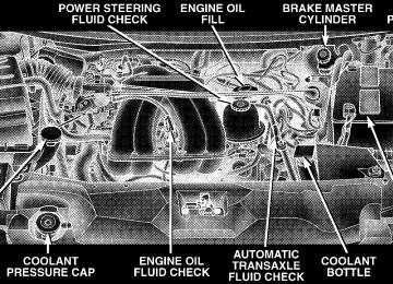
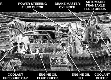
TO OPEN AND CLOSE THE HOOD To open the hood, two latches must be released. First pull the hood release lever located under the left side of the instrument panel.
96 UNDERSTANDING THE FEATURES OF YOUR VEHICLE
WARNING!
† Not all head restraints in this vehicle are the same. Head restraints from one seating position should not be removed and installed in any other seating position. In a collision, serious injury or death may result if the proper head restraint is not installed on each seat. † The cargo area in the rear of the vehicle should not be used as a play area by children. They could be seriously injured in a collision. Children should be seated and using the proper restraint system. † It is extremely dangerous to ride in a cargo area, inside or outside of a vehicle. In a collision, people riding in these areas are more likely to be seriously injured or killed. † Do not allow people to ride in any area of your vehicle that is not equipped with seats and seat belts. † Be sure everyone in your vehicle is in a seat and
using a seat belt properly.
Next, push to the left the safety catch located under the front edge of the hood, near the center.
Use the hood prop rod to secure the hood in the open position.
UNDERSTANDING THE FEATURES OF YOUR VEHICLE 97
To prevent possible damage, do not slam the hood to close it. Lower the hood until it is open approximately 30
cm (12 inches) and then drop it. This should secure both latches. Never drive your vehicle unless the hood is fully closed, with both latches engaged.WARNING!
If the hood is not fully latched, it could fly up when the vehicle is moving and block your forward vision. You could have a collision. Be sure all hood latches are fully latched before driving.
98 UNDERSTANDING THE FEATURES OF YOUR VEHICLE
LIGHTS All of the lights, except the hazard warning lights, are controlled by switches to the left of the steering column on the instrument panel.
Interior Lights Interior lights are turned on when a door or liftgate is opened, the keyless entry transmitter is activated, or when the dimmer control is moved to the extreme top. NOTE: On long wheel base vehicles the dome lights for the second row seat passenger’s can be turned on or off by pressing the lens. The lights will remain on until the lens is pressed a second time, so be sure they have been turned off before leaving the vehicle. The interior lights will automatically turn off in about 15
minutes if any of the following occur. † A door, sliding door or the liftgate is left open. † Any overhead reading light is left on. † If the dimmer control is in the extreme top position.NOTE: The key must be out of the ignition switch or the ignition switch must be in the OFF position for this feature to operate. Park Lights
Dimmer Control
UNDERSTANDING THE FEATURES OF YOUR VEHICLE 99
With the park lights or headlights on, rotating the dimmer control for the interior lights on the in- strument panel upward will in- crease the brightness of the instru- ment panel lights.
Turn this switch to the first detent to turn the park lights on. This also turns on all instrument panel
lighting. Headlights
Turn the headlight switch to the 2nd detent to turn the headlights and park lights on. This also turns on all instrument panel lighting.
To change the brightness of the instrument panel lights, rotate the dimmer control up or down.
Dome Light Position
Rotate the dimmer control com- pletely upward to the second de- tent (extreme top position) to turn on the interior lights, except the front reading/courtesy lights. The interior remain on when the dimmer control is in this position.
lights will
100 UNDERSTANDING THE FEATURES OF YOUR VEHICLE
Interior light Defeat (OFF)
Rotate the dimmer control to the OFF position (extreme bottom). The interior lights will remain off when the doors or liftgate are open.
Parade Mode (Daytime Brightness Feature)
Rotate the dimmer control to the first detent. This feature brightens the odometer, radio and overhead displays when the park lights or headlights are on.
Automatic Headlights — If Equipped
This system automatically turns your headlights ON or OFF based on ambient light levels. To turn the system ON, turn the headlight switch to the extreme counter- clockwise position. When the sys- tem is ON, the Headlight Time Delay feature is also ON. This means your headlights will stay ON for up to 90 seconds after you turn the ignition switch OFF. To turn the Automatic System OFF, turn the headlight switch clockwise to the OFF position. NOTE: The engine must be running before the head- lights will come ON in the Automatic mode.
Daytime Running Lights (Canada/Fleet Vehicles Only) The Daytime Running Lights will come on whenever the vehicle is running, the headlights are off, and the parking brake is off. The headlight switch must be used for normal night time driving. Lights-on Reminder If the headlights or the park lights are left on, or if the dimmer control is in the extreme top position after the ignition switch is turned off, a chime will sound when the driver’s door is opened. Battery Protection This feature provides battery protection to avoid wearing down the battery if the headlights, park lights, or front fog lights are left on for extended periods of time when the ignition switch is in the LOCK position. After 3
minutes of the ignition switch being in the LOCK posi- tion and the headlight switch in any position other thanUNDERSTANDING THE FEATURES OF YOUR VEHICLE 101
OFF or AUTO, the lights will turn off automatically until the next cycle of the ignition switch or headlight switch. The battery protection feature will be disabled if the ignition switch is turned to any other position other than LOCK during the 3 minute delay. Headlight Time Delay — If Equipped This feature provides the safety of headlight illumination for up to 90 seconds, when leaving your vehicle in an unlighted area. To activate the delay feature, turn off the ignition switch while the headlights are still on. Then turn off the headlights within 45 seconds. The 90 second delay inter- val begins when headlight switch is turned off. If the headlights or park lights are turned back on or the ignition switch is turned on, the delay will be cancelled. If the headlights are turned off before the ignition, they will turn off in the normal manner.
If either indicator flashes at a rapid rate, check for a defective outside turn signal light bulb. If one of the indicators fails to light when the lever is moved, it would suggest that the indicator light is defective.
102 UNDERSTANDING THE FEATURES OF YOUR VEHICLE
NOTE: The lights must be turned off within 45 seconds of turning the ignition off to activate this feature Front Fog Lights — If Equipped
To activate the front fog lights, turn on the park lights or the low beam headlights and pull out on the headlight switch control knob. An indicator in the headlight switch shows that the front fog lights are on. Pressing the headlight switch control knob in will turn the front fog lights off.
MULTIFUNCTION LEVER
Turn Signals Move the Multifunction Lever up or down and the arrows on each side of the base instrument cluster or Information Center flash to indicate proper operation of the front and rear turn signal lights. You can signal a lane change by moving the lever partially up or down.
Turn Signal Warning If the vehicle electronics sense that the vehicle has traveled at over 18 mph (29 km/h) for about one mile with the turn signals on, a chime will sound to alert the driver. Headlight Low/High Beam Selector Switch Pull the multifunction lever toward the steering wheel to switch the headlights between HIGH and LOW beam. Passing Light You can signal another vehicle with your headlights by lightly pulling the multifunction lever toward the steer- ing wheel. This will cause the headlights to turn on at high beam and remain on until the lever is released. Windshield Wipers and Washers The wipers and washers are operated by a switch in the multifunction lever. Rotate the end of the lever to select the desired wiper speed.
UNDERSTANDING THE FEATURES OF YOUR VEHICLE 103
NOTE: Always remove any build-up of snow that prevents the windshield wiper blades from returning to the OFF position. If the windshield wiper switch is turned OFF and the blades cannot return to the OFF position, damage to the wiper motor may occur.
To use the washer, press the end of the multifunction lever in when spray is desired, the washers will spray for
104 UNDERSTANDING THE FEATURES OF YOUR VEHICLE
a maximum of 20 seconds or until the lever is released. If another washer cycle is desired the end of the lever must be pressed again to get another 20 second washer cycle. If the lever is depressed while in the delay range, the wipers will operate for several seconds after the lever is released, and then resume the intermittent interval pre- viously selected. If the end of the lever is depressed while in the OFF position, the wipers will operate for approximately two wipe cycles, then turn OFF.
WARNING!
Sudden loss of visibility through the windshield could lead to an accident. You might not see other vehicles or other obstacles. To avoid sudden icing of the windshield during freezing weather, warm the windshield with defroster before and during wind- shield washer use.
Intermittent Wiper System Use the intermittent wipers when weather conditions make a single wiping cycle, with a variable pause be- tween cycles, desirable. Rotate the end of the lever to the first detent position, then turn the end of the lever to select the desired delay interval. The delay can be regulated from a maximum of about 20 seconds between cycles, to a cycle every 2
seconds. The time delay will be doubled if the vehicle speed is less than 10 mph (16 km/h).TILT STEERING COLUMN — IF EQUIPPED To tilt the column, pull the small lever, located behind the turn signal control, toward you and move the wheel up or down, as desired. Release the lever to lock the wheel firmly in place.
UNDERSTANDING THE FEATURES OF YOUR VEHICLE 105
TRACTION CONTROL SWITCH — IF EQUIPPED The TRAC indicator, located below the instrument clus- ter odometer, will light up when the Traction Control is in use. To turn the system OFF, press the TRAC OFF switch located on the steering column, until the TRAC OFF indicator below the instrument cluster odometer lights up.
WARNING!
Tilting the steering column while the vehicle is moving is dangerous. Without a stable steering col- umn, you could lose control of the vehicle and have an accident. Adjust the column only while the ve- hicle is stopped. Be sure it is locked before driving.
106 UNDERSTANDING THE FEATURES OF YOUR VEHICLE
To turn the system back ON, press the switch a second time until the TRAC OFF indicator turns OFF. NOTE: † The Traction Control System indicator comes on each time the ignition switch is turned ON. This will occur even if you used the switch to turn the system OFF. † The Traction Control will make buzzing or clicking
sounds when in operation.
ADJUSTABLE PEDALS — IF EQUIPPED This feature allows both the brake and accelerator pedals to move toward or away from the driver to provide improved position with the steering wheel. The adjust- able pedal system is designed to allow a greater range of driver comfort for steering wheel tilt and seat position. The switch is located on the right side of the steering column.
Press the button forward to move the pedals forward (toward the front of the vehicle). Press the button rearward to move the pedals rearward (toward the driver). † The pedals can be adjusted with the ignition OFF. † The pedals can be adjusted while driving.
UNDERSTANDING THE FEATURES OF YOUR VEHICLE 107
ELECTRONIC SPEED CONTROL — IF EQUIPPED When engaged, this device takes over the accelerator operation at speeds greater than 30 mph (50 km/h). The speed control switches are located on the steering wheel.
† The pedals cannot be adjusted when the vehicle is in R (Reverse) or when the Speed Control System is ON. The following messages will be displayed on vehicles equipped with the Electronic Vehicle Information Sys- tem (EVIC) if the pedals are attempted to be adjusted when the system is locked out (“Adjustable Pedal Disabled — Cruise Control Engaged” or “Adjustable Pedal Disabled — Vehicle In Reverse”).
CAUTION!
Do not place any article under the adjustable pedals or impede its ability to move as it may cause damage to the pedal controls. Pedal travel may become limited if movement is stopped by an obstruction in the adjustable pedal’s path.
108 UNDERSTANDING THE FEATURES OF YOUR VEHICLE
To Activate: Push the “ON/OFF” button once and the CRUISE indi- cator located below the instrument cluster odometer will illuminate showing the electronic speed control system is on. To turn the system OFF, push the “ON/OFF” button again and the system and indicator will turn off.
WARNING!
Leaving the Electronic Speed Control system on when not in use is dangerous. You could accidently set the system or cause it to go faster than you want. You could lose control and have an accident. Always leave the system OFF when you aren’t using it.
To Set At A Desired Speed:
When the vehicle has reached the desired speed, press and release the “SET” button. Release the accelerator and the vehicle will operate at the selected speed. To Deactivate: A soft tap on the brake pedal, pushing the “CANCEL” button or normal braking while slowing the vehicle will deactivate the speed control without erasing the set speed memory. Pushing the “ON/OFF” button to the OFF position or turning off the ignition erases the set speed memory. To Resume Speed: To resume a previously set speed, push and release the “RESUME/ACCEL” button. Resume can be used at any speed above 40 km/h (25 mph).
To Vary the Speed Setting: When the speed control is set, speed can be increased by pressing and holding the “RESUME/ACCEL” button. When the button is released, a new set speed will be established. Tapping the “RESUME/ACCEL” button once will result in a 2 mph (3 km/h) speed increase. Each time the button is tapped, speed increases so that tapping the button three times will increase speed by 6 mph (10 km/h), etc. To decrease speed while speed control is set, press and hold the “COAST” button. Release the button when the desired speed is reached, and the new speed will be set. Tapping the “COAST” button once will result in a 1 mph (2 km/h) speed decrease. Each time the button is tapped, speed decreases.
UNDERSTANDING THE FEATURES OF YOUR VEHICLE 109
To Accelerate For Passing: Depress the accelerator as you would normally. When the pedal is released, the vehicle will return to the set speed. NOTE: The speed control system maintains speed up and down hills. A slight speed change on moderate hills is normal. Your vehicle will experience a downshift to 3rd gear while climbing uphill or descending downhill. This downshift to 3rd gear is necessary to maintain vehicle set speed. On steep hills a greater speed loss or gain may occur so it may be preferable to drive without speed control.
110 UNDERSTANDING THE FEATURES OF YOUR VEHICLE
WARNING!
Speed Control can be dangerous where the system can’t maintain a constant speed. Your vehicle could go too fast for the conditions, and you could lose control. An accident could be the result. Don’t use Speed Control in heavy traffic or on roads that are winding, icy, snow-covered, or slippery.
OVERHEAD CONSOLE — IF EQUIPPED The overhead console can contain courtesy/reading lights, an optional universal garage door opener (HomeLinkt), compass/ temperature display, a mini-trip computer, optional elec- tronic vehicle information center (EVIC), power sliding door switches and an optional power liftgate switch.
sunglasses,
storage
for
Courtesy/Reading Lights
At the forward end of the console are two courtesy/ reading lights. Press the lens to turn these lights on. Press a second time to turn the lights off.
The lights also turn on when a front door, a sliding door or the liftgate is opened. If your vehicle is equipped with Remote Keyless Entry, the lights will also turn on when the unlock button on the transmitter is pressed. The area around the instrument panel cupholders is also illuminated from a light in the overhead console. This light is turned on when the headlight switch is on and will adjust in brightness when the dimmer control is rotated up or down. Sunglass Storage At the rear of the console a compartment is provided for the storage of two pair of sunglasses. Press the door latch to open the compartment. The door will slowly rotate to an open position.
UNDERSTANDING THE FEATURES OF YOUR VEHICLE 111
Compass/Temperature Display This display provides the outside temperature and one of eight compass readings to indicate the direction the vehicle is facing.
WARNING!
Even if the display still reads a few degrees above 32°F ( 0°C), the road surface may be icy, particularly in woods or on bridges. Drive carefully under such conditions to prevent an accident and possible per- sonal injury or property damage.
Automatic Compass Calibration This compass is self calibrating which eliminates the need to manually set the compass. When the vehicle is new, the compass may appear erratic and the “CAL” symbol will be displayed. After completing three 360°
112 UNDERSTANDING THE FEATURES OF YOUR VEHICLE
turns in an area free from large metal or metallic objects, the “CAL” symbol will turn off and the compass will function normally. Manual Compass Calibration If the compass appears erratic and the “CAL” symbol does not appear, you must put the compass into the Calibration Mode manually. To put into a Calibration Mode: Turn on the ignition switch and set the display to Comp/Temp. Press the RESET button on vehicles equipped with a Compass/ Mini Trip Computer for at least 10 seconds until the “CAL” symbol appears. On vehicles equipped with Compass/Temp press and hold the C/T and US/M buttons for 10 seconds. Release the RESET button and complete three 360° turns in an area free from large metal objects. The “CAL” symbol will turn off and the compass will function normally.
CAUTION!
Do not place any external magnets, such as magnetic roof mount antennas, in the vicinity of the compass. Do not use magnetic tools when servicing the over- head console.
Compass Variance Compass Variance is the difference between magnetic North and Geographic North. In some areas of the country, the difference between magnetic and geographic North is great enough to cause the compass to give false readings. If this occurs, the compass variance must be set. NOTE: Magnetic materials should be kept away from the overhead console.
UNDERSTANDING THE FEATURES OF YOUR VEHICLE 113
To set the variance: Turn the ignition switch ON and set the display to Comp/Temp. On vehicles equipped with a Compass/Mini Trip Computer press the RESET button for approximately 5 seconds. On vehicles equipped with Compass/Temp press and hold the C/T and US/M buttons for 5 seconds. The “VAR” symbol will light and the last variance zone number will be displayed. Press the STEP button on vehicles equipped with a Compass/ Mini Trip Computer or the US/M button on vehicles equipped with Compass/Temp to select the proper vari- ance zone as shown in the map. Press the RESET button on vehicles equipped with a Compass/Mini Trip Com- puter or the C/T button on vehicles equipped with Compass/Temp to set the new variance zone and resume normal operation.
114 UNDERSTANDING THE FEATURES OF YOUR VEHICLE
Mini-Trip Computer This displays information on the following: † Average Fuel Economy (ECO AVG) Shows the average fuel economy since the last reset. † Distance To Empty (DTE) Shows the estimated distance that can be travelled with the fuel remaining in the tank. This estimated distance is determined using the MPG for the last few minutes. † Trip Odometer (ODO) Shows the distance travelled since the last reset. † Elapsed Time (ET) Shows the accumulated ignition ON time since the last reset. † Off Mode Shows a blank display.
† Step Button Push this button to cycle through all the Compass/Mini- trip Computer displays. † US/M Button Press this button to convert the display from U.S. to metric. To Reset The Display Pressing the Reset button once will clear the resettable function currently being displayed. Resettable functions are average fuel economy, trip odometer and elapsed time. Pressing the reset button twice within four seconds will clear all resettable functions. Reset will only occur if a resettable function is currently being displayed.
Electronic Vehicle Information Center (EVIC) — If Equipped The Electronic Vehicle Information Center, when the appropriate conditions exist, displays the following WARNING messages and symbols. Each message is accompanied by a single chime: † TURN SIGNALS ON (with graphic) † PERFORM SERVICE † DOOR AJAR (one or more, with graphic) † LIFTGATE AJAR (with graphic) † WASHER FLUID LOW (with graphic) † 1,2,3 OR 4 LOW TIRE(S) PRESSURE (Refer to “Starting † 1,2,3 OR 4 HIGH TIRE(S) PRESSURE (Refer to “Start-
And Operating, Tire Section”)
ing And Operating, Tire Section”)
UNDERSTANDING THE FEATURES OF YOUR VEHICLE 115
And Operating, Tire Section”)
ing And Operating, Tire Section”)
† SERVICE TIRE PRESS. SYSTEM/SEE OWNER’S MANUAL (Refer to “Starting And Operating, Tire Section”) † TIRE PRESSURE UNAVAILABLE (Refer to “Starting † TIRE PRESSURE NOW AVAILABLE (Refer to “Start- † SPARE TIRE IN USE? YES/NO (Refer to “Starting † ALL 5 TIRES WITH CAR? YES/NO (Refer to “Starting † MEMORY SEAT DISABLED (Not in Park) — If † ADJUSTABLE PEDAL DISABLED/CRUISE ENGAGED † ADJUSTABLE PEDAL DISABLED/VEHICLE IN RE-
And Operating, Tire Section”)
And Operating, Tire Section”)
Equipped
VERSE
116 UNDERSTANDING THE FEATURES OF YOUR VEHICLE
NOTE: Tire pressure menu items are available only on vehicles equipped with the Tire Pressure Monitor Sys- tem. Customer Programmable Features — If Equipped Press the “MENU” button until one of the display choices following appears: Language When in this display you may select one of five lan- guages for all display nomenclature, including the trip computer functions. Press the “STEP” button while in this display selects English, Francaise, Deutsch, Italiano, or Espanol. As you continue the displayed information will be shown in the selected language. US or Metric Pressing the “STEP” button when in this display selects US or Metric. The overhead console and climate control displays will be in the selected units.
Service Interval When this feature is selected a service interval between 2,000 miles (3 200 km) and 6,000 miles (9 600 km) in 500
mile (800 km) increments may be selected. Pressing the “STEP” button when in this display will select distances between 2,000 miles (3 200 km) and 6,000 miles (9 600
km) in 500 mile (800 km) increments. Reset Service Distance (Displays Only if Service Interval was Changed) When this feature is selected the current accumulated service distance can be reset to the newly selected service interval. Pressing the “STEP” button when in this display will select “Yes” or “No.” Retrain Tire Sensors (Available with Tire Pressure Monitor System Only) The Tire Pressure Monitor system must be retrained following a tire rotation or wheel rim mounted sensor replacement. If you unintentionally choose “Yes” to trainthe Tire Pressure Monitor system and the training routine is not performed, training will be cancelled after one minute or the next time you cycle the ignition key. See your authorized dealer for service and retraining of the system. Use Factory Settings If “Yes” is selected, all of the customer programmable features will be set to the factory default and not dis- played. If “No” is selected you can program the Vehicle Information Center to your own personal preferences. Auto Door Locks When this feature is selected, all doors and the liftgate lock automatically when the speed of the vehicle reaches 18 mph (29 km/h). Pressing the “STEP” button when in this display will select “Yes” or “No.”
UNDERSTANDING THE FEATURES OF YOUR VEHICLE 117
Auto Unlock On Exit (Available Only When the AUTO DOOR LOCKS Feature is Turned On) When this feature is selected all the vehicle’s doors will unlock whenever any door is opened if the vehicle is stopped and the transmission is in “P” (Park) or “N” (Neutral) position. Pressing the “STEP” button when in this display will select “Yes” or “No.” Remote Unlock Driver’s Door 1st When this feature is selected only the driver’s door will unlock on the first press of the remote keyless entry unlock button and require a second press to unlock the remaining locked doors and liftgate. When “REMOTE UNLOCK ALL DOORS” is selected all of the doors and the liftgate will unlock at the first press of the remote keyless entry unlock button. Pressing the “STEP” button when in this display will select “DRIVER’S DOOR 1ST” or “ALL DOORS”.
118 UNDERSTANDING THE FEATURES OF YOUR VEHICLE
Remote Linked To Memory (Available with Memory Seat and Pedals Only) When this feature is selected, pressing the Unlock button on any Remote Keyless Entry transmitter already linked to memory will return the driver’s seat, driver’s outside mirror, adjustable brake and accelerator pedals, and radio station presets to their memory set positions. If this feature is not selected, the driver’s seat, driver’s mirror, adjustable pedals, and radio settings can only return to their memory set positions using the memory recall buttons (1or 2) on the driver’s door panel. Any transmitter linked to memory will remain linked, but will not recall the memory positions. The transmitter memory recall function will operate again when this feature is selected. Refer to Driver Memory System for more information. Pressing the 9STEP9 button when in this mode will select between 9Yes9 or 9No9.
Sound Horn On Lock When this feature is selected a short horn sound will occur when the remote keyless entry “Lock” button is pressed. This feature may be selected with or without the flash lights on LOCK/UNLOCK feature. Pressing the “STEP” button when in this display will select “Yes” or “No.” Flash Lights On Lock/Unlock? When this feature is selected, the front and rear turn signals will flash when the doors are locked or unlocked using the remote keyless entry transmitter. This feature may be selected with or without the sound horn on lock feature selected. Pressing the “STEP” button when in this display will select “Yes” or “No.” Headlamp Delay When this feature is selected the driver can choose, when exiting the vehicle, to have the headlamps remain on for
30, 60, or 90 seconds, or not remain on. Pressing the “STEP” button when in this display will select 30, 60, 90, or “OFF.” Headlamp On With Wipers (Available with Auto Headlights Only) When this feature is selected and the headlight switch has been moved to the “AUTO” position, the engine is running and, the front wipers are turned on for 10
seconds, the headlights will turn ON. The display will remain on Parade Mode (Daytime Brightness) for ease of viewing. Pressing the “STEP” button when in this display will select “Yes” or “No.” Power Accessory Delay When this feature is selected, accessory power will be supplied for up to 45 seconds for the power windows,UNDERSTANDING THE FEATURES OF YOUR VEHICLE 119
radio, power vent windows, power outlets, and remov- able center console, when the ignition switch is turned off or until the key is removed and either front door is opened.
GARAGE DOOR OPENER — IF EQUIPPED The HomeLinkt Universal Transceiver replaces up to three remote controls (hand held transmitters) that oper- ate devices such as garage door openers, motorized gates, or home lighting. It triggers these devices at the push of a button. The Universal Transceiver operates off your vehicle’s battery and charging system; no batteries are needed. For additional information on HomeLinkt, call 1–800– 355–3515, or on the internet at www.homelink.com.
120 UNDERSTANDING THE FEATURES OF YOUR VEHICLE
WARNING!
Programming HomeLink
A moving garage door can cause injury to people and pets in the path of the door. People or pets could be seriously or fatally injured. Only use this transceiver with a garage door opener that has a “stop and reverse” feature as required by federal safety stan- dards. This includes most garage door opener mod- els manufactured after 1982. Do not use a garage door opener without these safety features it could cause injury or death. Call toll-free 1–800–355–3515
or, on the Internet at www.homelink.com for safety information or assistance.NOTE: When programming a garage door opener, it is advised to park outside the garage. Some vehicles may require the ignition switch to be turned to the second (or 9accessories9) position for programming and/or opera- tion of HomeLink. It is also recommended that a new battery be placed in the hand-held transmitter of the device being programmed to HomeLink for quicker training and accurate transmission of the radio-frequency signal. 1. Press and hold the two outer HomeLink buttons, and release only when the indicator light begins to flash (after 20 seconds). Do not hold the buttons for longer than 30
seconds and do not repeat step one to program a second and/or third hand-held transmitter to the remaining two HomeLink buttons.UNDERSTANDING THE FEATURES OF YOUR VEHICLE 121
WARNING!
Your motorized door or gate will open and close while you are training the Universal Transceiver. Do not train the transceiver if people or pets are in the path of the door or gate. A moving door or gate can cause serious injury or death to people and pets or damage to objects.
2. Position the end of your hand-held transmitter 1-3
inches (3-8 cm) away from the HomeLink buttons while keeping the indicator light in view. 3. Simultaneously press and hold both the HomeLink button that you want to train and the hand-held trans- mitter buttons. Do not release the buttons until step 4
has been completed.WARNING!
Vehicle exhaust contains carbon monoxide, a danger- ous gas. Do not run the vehicle’s exhaust while training the transceiver. Exhaust gas can cause seri- ous injury or death.
122 UNDERSTANDING THE FEATURES OF YOUR VEHICLE
NOTE: Some gate operators and garage door openers may require you to replace this Programming Step 3 with procedures noted in the 9Gate Operator/Canadian Pro- gramming9 section. 4. The HomeLink indicator light will flash slowly and then rapidly after HomeLink successfully receives the frequency signal from the hand-held transmitter. Release both buttons after the indicator light changes from the slow to the rapid flash. 5. Press and hold the just trained HomeLink button and observe the indicator light. If the indicator light stays on constantly, programming is complete and your device should activate when the HomeLink button is pressed and released. NOTE: To program the remaining two HomeLink but- tons, begin with 9Programming9 step two. Do not repeat step one.
If the indicator light blinks rapidly for two seconds and then turns to a constant light continue with (Program- ming( steps 6-8 to complete the programming of a rolling code equipped device (most commonly a garage door opener). 6. At the garage door opener receiver (motor-head unit) in the garage, locate the 9learn9 or 9smart9 button. This can usually be found where the hanging antenna wire is attached to the motor-head unit. 7. Firmly press and release the 9learn9 or 9smart9 button. (The name and color of the button may vary by manu- facturer.) NOTE: There are 30 seconds in which to initiate step eight. 8. Return to the vehicle and firmly press, hold for two seconds and release the programmed HomeLink button. Repeat the (press/hold/release( sequence a second time,
rolling code
and, depending on the brand of the garage door opener (or other rolling code equipped device), repeat this sequence a third time to complete the programming. HomeLink should now activate your equipped device. NOTE: To program the remaining two HomeLink but- tons, begin with 9Programming9 step two. Do not repeat step one. For questions or comments, please contact HomeLink at www.homelink.com or 1-800-355-3515. Canadian Programming/Gate Programming Canadian radio-frequency laws require transmitter sig- nals to 9time-out9 (or quit) after several seconds of transmission which may not be long enough for HomeLink to pick up the signal during programming. Similar to this Canadian law, some U.S. gate operators are designed to 9time-out9 in the same manner.
UNDERSTANDING THE FEATURES OF YOUR VEHICLE 123
If you live in Canada or you are having difficulties programming a gate operator by using the 9Program- ming9 procedures (regardless of where you live), replace (Programming HomeLink( step 3 with the following: If programming a garage door opener or gate NOTE: operator, it is advised to unplug the device during the 9cycling9 process to prevent possible overheating. 3. Continue to press and hold the HomeLink button while you press and release every two seconds (9cycle9) your hand-held transmitter until the frequency signal has successfully been accepted by HomeLink. (The indicator light will flash slowly and then rapidly.) Proceed with 9Programming9 step four to complete. Using HomeLink To operate, simply press and release the programmed HomeLink button. Activation will now occur for the trained device (i.e. garage door opener, gate operator, security system, entry door lock, home/office lighting,
124 UNDERSTANDING THE FEATURES OF YOUR VEHICLE
etc.). For convenience, the hand-held transmitter of the device may also be used at any time. In the event that there are still programming difficulties or questions, contact HomeLink at: www.homelink.com or 1-800-355- 3515. Erasing HomeLink Buttons To erase programming from the three buttons (individual buttons cannot be erased but can be 9reprogrammed9 - note below), follow the step noted: † Press and hold the two outer HomeLink buttons until the indicator light begins to flash-after 20 seconds. Release both buttons. Do not hold for longer that 30
seconds. HomeLink is now in the train (or learning) mode and can be programmed at any time beginning with 9Programming9 - step 2.Reprogramming a Single HomeLink Button To program a device to HomeLink using a HomeLink button previously trained, follow these steps: 1. Press and hold the desired HomeLink button. Do NOT release the button. 2. The indicator light will begin to flash after 20 seconds. Without releasing the HomeLink button, proceed with 9Programming9 step 2
For questions or comments, contact HomeLink at: www.homelink.com or 1-800-355-3515. Security If you sell your vehicle, be sure to erase the frequencies. To erase all of the previously trained frequencies, hold down both outside buttons until the green light begins to flash.This device complies with part 15 of FCC rules and with RSS-210 of Industry Canada. Operation is subject to the following conditions: † This device may not cause harmful interference. † This device must accept any interference that may be received including interference that may cause undes- ired operation.
NOTE: Changes or modifications not expressly ap- proved by the party responsible for compliance could void the user’s authority to operate the equipment. HomeLinkt is a trademark owned by Johnson Controls, Inc.
UNDERSTANDING THE FEATURES OF YOUR VEHICLE 125
POWER SUNROOF — IF EQUIPPED The power sunroof control is located between the sun visors on the overhead console.
Press and hold the switch rearward to fully open the sunroof. The sunroof can be stopped at any position between closed and full open. Momentarily pressing the
126 UNDERSTANDING THE FEATURES OF YOUR VEHICLE
switch rearward will activate the Express Open Feature, causing the sunroof to open automatically. Press and hold the button located to the right of the sunroof switch, to open the vent. The sunroof can be stopped at any position between closed and full vent. To close the sunroof from the vent position, press and hold the switch forward. Releasing the switch will stop the movement of the sunroof and the sunroof will remain in the partial vent position until the switch is pushed forward again. Express Open Feature During the Express Open operation, any movement of the switch will stop the sunroof and it will remain in a partial open position. Again, momentarily pressing the switch rearward will activate the Express Open Feature. To close the sunroof, hold the switch in the forward position. Again, any release of the switch will stop the
movement and the sunroof will remain in a partial open condition until the switch is pushed forward again. The sunshade can be opened manually. It will also open as the sunroof opens. The sunshade cannot be closed if the sunroof is open.
WARNING!
Never leave children in a vehicle, with the keys in the ignition switch. Occupants, particularly unat- tended children, can become entrapped by the power sunroof while operating the power sunroof switch. Such entrapment may result in serious injury or death.
WARNING!
In an accident, there is a greater risk of being thrown from a vehicle with an open sunroof. You could also be seriously injured or killed. Always fasten your seat belt properly and make sure all passengers are properly secured too. Do not allow small children to operate the sunroof. Never allow fingers or other body parts, or any object to project through the sunroof opening. Injury may result.
Wind Buffeting Wind buffeting can be described as the perception of pressure on the ears or a helicopter type sound in the ears. Your vehicle may exhibit wind buffeting with the windows down, or the sunroof (if equipped) in certain
UNDERSTANDING THE FEATURES OF YOUR VEHICLE 127
open or partially open positions. This is a normal occur- rence and can be minimized. If the buffeting occurs with the rear windows open, open the front and rear windows together to minimize the buffeting. If the buffeting occurs with the sunroof open, adjust the sunroof opening to minimize the buffeting or open any window. Sunroof Maintenance Use only a non-abrasive cleaner and a soft cloth to clean the glass panel.
ELECTRICAL POWER OUTLETS — IF EQUIPPED To the left of the instrument panel cup holder are two 12
volt power outlets. The upper outlet is controlled by the ignition switch and the lower outlet is connected directly to the battery. The upper outlet will also operate a conventional cigar lighter unit (if equipped with an optional Smoker’s Package).128 UNDERSTANDING THE FEATURES OF YOUR VEHICLE
A third outlet is located on the driver’s side, just to the rear of the sliding door and is also controlled by the ignition switch. The lower and rear outlets will not accommodate a conventional cigar lighter unit.
instrument panel outlet is powered directly from the battery, items plugged into this outlet may discharge the battery and/or prevent engine starting. The lower outlet is protected by an automatic reset circuit breaker. The automatic circuit breaker restores power when the overload is removed. The circuit breaker also supplies power to the outlet in the removable floor console, when in the front position. Refer to section 3
“Removable Floor Console” in this manual. If desired, all of the power outlets can be NOTE: converted by your authorized dealer to provide power with the ignition switch in the OFF position.The outlets include tethered caps labeled with a key or battery symbol indicating the power source. The lower
Electrical Outlet Use With Engine Off
CAUTION!
† Accessories that draw higher power
† Many accessories that can be plugged in draw power from the vehicle’s battery, even when not in use (i.e. cellular phones, etc.). Eventually, if plugged in long enough, the vehicle’s battery will discharge sufficiently to degrade battery life and/or prevent engine starting. (i.e. coolers, vacuum cleaners, lights, etc.), will degrade the battery even more quickly. Only use these intermittently and with greater caution. † After the use of high power draw accessories, or long periods of the vehicle not being started (with accesso- ries still plugged in), the vehicle must be driven a sufficient length of time to allow the alternator to recharge the vehicle’s battery. † Power outlets are designed for accessory plugs only. Do not hang any type of accessory or accessory bracket from the plug. Improper use of the power outlet can cause damage not covered by your warranty.
UNDERSTANDING THE FEATURES OF YOUR VEHICLE 129
CONVENIENCE TRAY DRAWER AND CUP HOLDERS
Instrument Panel Cup Holders The instrument panel cupholders are located in a pull out drawer just below the climate controls.
When the drawer is pulled out firmly, the arms of the cupholders will spring out. Place the container to be held
130 UNDERSTANDING THE FEATURES OF YOUR VEHICLE
into one of the cupholders and then push the arm toward the container until the container is held stable. There are adjustable positions for the arm so the cupholder can accommodate a wide variety of container types and sizes, including those with handles. The arms of the cupholder can be adjusted in or out without damaging the detent mechanism. NOTE: Be sure the drawer is pulled out completely, otherwise the adjustable arm detents will not engage and the container will not be held stable. Convenience Tray And Optional Smoker’s Package Kit Located between the instrument panel cupholders is a convenience tray that has been designed to hold miscel- laneous small items. NOTE: The convenience tray should never be used for ashes without the optional ash receiver in place. Perma- nent burn marks may result.
With the optional dealer installed Smoker’s package, a removable ash receiver is inserted into the convenience tray location. To install the ash receiver, slide the forward edge into the convenience tray opening and push down to lock it into position. For cleaning of the ash receiver, its removal is accomplished by inserting the end of a key in the pry slot that is molded into the rear edge of the ash receiver and then twisting the key slightly. Rear Cupholders There are dual stationary cupholders located in the passenger side rear trim panel and a single stationary cup holder on the driver side rear trim panel. There are also dual underseat cupholders for the 2nd seat passengers. With a bench seat in the 2nd seat position these cupholders slide out from under the center of the seat.
If your vehicle is equipped with quad seats in the 2nd seat position, these cupholders are located on the out- board side of the seat pedestal.
UNDERSTANDING THE FEATURES OF YOUR VEHICLE 131
seat is tilted forward.
NOTE: † The quad seat cupholders will remain upright if the † The quad seat cupholders are designed to break away if stepped on. To return the cupholder to its normal position, simply push the cupholder up to snap it into place. † The floor mat must be in position for optimum cup-
holder operation.
There are also two cupholders and a flat tray on the seat back of the quad seats. These can be used when the seat back is folded forward.
132 UNDERSTANDING THE FEATURES OF YOUR VEHICLE
STORAGE
Front Seat Storage Bin — If Equipped The storage bin is located under the front passenger’s seat. If equipped with a lock, it can be locked with the ignition key.
Removable Floor Console — If Equipped The removal floor console has a power outlet, storage tray, light, cell phone holder, tissue holder, and a map holder. It can be placed between either the front seats or middle seats. NOTE: When the console is located between the front seats the outlet is protected by an automatic circuit breaker and is powered directly from the battery, items plugged into this outlet may discharge the battery and/or prevent engine starting.
UNDERSTANDING THE FEATURES OF YOUR VEHICLE 133
To remove the console use the following procedure: 1. Open the rear lid and remove the storage tray. 2. Pull the release handle located inside the floor console, reinstall the storage tray and close the rear lid.
3. Using the front and rear grab handles, slide the console rearward to disengage the front of the console and lift up to remove the console from the floor. 4. Place the rubber mat on the floor tray. To reinstall the console, remove the rubber mat and relocate to the alternate floor tray, slide the console
134 UNDERSTANDING THE FEATURES OF YOUR VEHICLE
forward to engage the front of the console into the floor tray. Rapidly push down on the rear of the console with enough force to engage the latch, you should hear the latch “snap” into place. Pull up on the console to be sure it’s firmly attached. NOTE: When the removable floor console is located between the middle seats, the power outlet only has power supplied to it when the ignition switch is ON. Cell Phone Holder 1. Open the front lid and remove the cell phone holder by pulling rearward and up on the lower edge of the holder.
2. Plug in the power cord for the cellular phone into the outlet located in the bottom of the forward console bin and reinstall the cell phone holder 3. Place the cell phone into the holder.
CAUTION!
† Many accessories that can be plugged in draw power from the vehicle’s battery, even when not in use (i.e. cellular phones, etc.). Eventually, if plugged in long enough, the vehicle’s battery will discharge sufficiently to degrade battery life and/or prevent engine starting. † Accessories that draw higher power (i.e. coolers, vacuum cleaners, lights, etc.), will degrade the battery even more quickly. Only use these inter- mittently and with greater caution. † After the use of high power draw accessories, or long periods of the vehicle not being started (with accessories still plugged in), the vehicle must be driven a sufficient length of time to allow the generator to recharge the vehicle’s battery.
UNDERSTANDING THE FEATURES OF YOUR VEHICLE 135
Rear Compartment Storage Bins Your vehicle may be equipped with open storage bins located in each rear trim panel or your vehicle may be equipped with storage bins located under the armrest in each rear trim panel. Cargo Area Storage The seats in your vehicle are in-line which enables you to stow long objects, such as lumber or skis, on the floor without moving the seats. NOTE: With all rear seat backs folded, a 4x8 foot sheet of building material may be stored in the long-wheelbase body style on top of the folded seats with the liftgate closed. The front seats must be moved slightly forward of the rearmost position. If the rear seats are removed no front seat adjustment is needed and more than one 4x8
sheet of building material may be stored.136 UNDERSTANDING THE FEATURES OF YOUR VEHICLE
The liftgate sill plate has a raised line with the statement “Load To This Line”. This line indicates how far rearward cargo can be placed without interfering with liftgate closing.
Cargo Organizer — If Equipped Long wheel base vehicle with rear air conditioning may be equipped with a cargo organizer that mounts on the floor behind the rear seat. Items may be placed on the flat surface or stored in the three storage compartments.
WARNING!
positions.
† To avoid tipping, lock the shelf securely in all † Do not drive this vehicle with the liftgate open, or † Failure to follow these warnings could result in
use the shelf as a seat.
serious or fatal injury.
1. To raise the cargo organizer pull up on the handle and pull towards the rear of the vehicle.
UNDERSTANDING THE FEATURES OF YOUR VEHICLE 137
2. Place the rear corners of the cargo organizer into the supports located on the rear trim panel. Press down on the back of the cargo organizer to lock it into place.
138 UNDERSTANDING THE FEATURES OF YOUR VEHICLE
WARNING!
Do not load objects over 20 lbs (9 kg) in the upper position. Failure to follow this warning could cause the cargo organizer to collapse resulting in personal injury.
CAUTION!
Do not load objects over 100 lbs (45 kg) in the lower position. Failure to follow this could cause damage to the cargo organizer.
To Open Storage Compartments 1. Pull up on the center opening of the cargo organizer.
2. Lift up on the storage compartment dividers and lock into place.
Cargo Organizer removal Unscrew the two plastic fasteners located on the floor of the rear of the cargo area and remove the cargo organizer from the vehicle.
UNDERSTANDING THE FEATURES OF YOUR VEHICLE 139
ROOF LUGGAGE RACK — IF EQUIPPED The crossbars and siderails are designed to carry the weight on vehicles equipped with a luggage rack. The load must not exceed 150 lbs (68 kg), and should be uniformly distributed over the luggage rack crossbars.
NOTE: The cargo organizer must be removed to take out the third row seat.
Distribute cargo weight evenly on the roof rack crossbars. The roof rack does not increase the total load carrying
140 UNDERSTANDING THE FEATURES OF YOUR VEHICLE
capacity of the vehicle. Be sure the total load of cargo inside the vehicle plus that on the external rack does not exceed the maximum vehicle load capacity. To move the cross bars, press the upper edge of each cross bar button pass the detent, then move the cross bar to the desired position. Once the cross bar is in place, press the lower edge of the cross bar button to lock it into position. Attempt to move the crossbar again to ensure that it has properly locked into position.
NOTE: To help control wind noise when installing the cross bars make sure that the arrows marked on the front side of the cross bars are facing the front of the vehicle. Also, when the cross bars are not in use the notch on the cross bars should be aligned with the arrows on the side rails. This will help reduce the amount of wind noise when the crossbars are not in use. The tie down holes on the cross bar ends should always be used to tie down the load. Check the straps frequently to be sure that the load remains securely attached.
CAUTION!
† To avoid damage to the roof rack and vehicle, do not exceed the maximum roof rack load capacity of 150 lbs (68 kg). Always distribute heavy loads as evenly as possible and secure the load appro- priately. † Long loads which extend over the windshield, such as wood panels or surfboards, or loads with large frontal area should be secured to both the front and rear of the vehicle. † Travel at reduced speeds and turn corners care- fully when carrying large or heavy loads on the roof rack. Wind forces, due to natural causes or nearby truck traffic, can add sudden upward loads. This is especially true on large flat loads and may result in damage to the cargo or your vehicle.
UNDERSTANDING THE FEATURES OF YOUR VEHICLE 141
WARNING!
Cargo must be securely tied before driving your vehicle. Improperly secured loads can fly off the vehicle, particularly at high speeds, resulting in personal injury or property damage. Follow the Roof Rack Cautions when carrying cargo on your roof rack.
LOAD LEVELING SYSTEM The automatic load leveling system will provide a level riding vehicle under most passenger and cargo loading conditions. A hydraulic pump contained within the shock absorbers raises the rear of the vehicle to the correct height. It takes approximately 1 mile (1.6 km) of driving for the leveling to complete depending on road surface conditions.
142 UNDERSTANDING THE FEATURES OF YOUR VEHICLE
If the leveled vehicle is not moved for approximately 15
hours, the leveling system will bleed itself down. The vehicle must be driven to reset the system.WARNING!
Do not install the load leveling system on vehicles that are not equipped with Anti-Lock Brakes. Ve- hicles without Anti-Lock Brakes (ABS) have a height-sensing proportioning valve. Installing a lev- eling system will render this system ineffective, inappropriately reducing rear brake pressure, result- ing in increased stopping distances. You could have an accident.
UNDERSTANDING YOUR INSTRUMENT PANEL
CONTENTS
m Instruments And Controls . . . . . . . . . . . . . . . . . 148
m Base Instrument Cluster . . . . . . . . . . . . . . . . . . 149
m Instrument Cluster With Tach . . . . . . . . . . . . . . 150
m Instrument Cluster Descriptions . . . . . . . . . . . . 151
m Information Center — If Equipped . . . . . . . . . . 159
N Turn Signal Indicators . . . . . . . . . . . . . . . . . . 159
N High Beam Light . . . . . . . . . . . . . . . . . . . . . 159
m Electronic Digital Clock . . . . . . . . . . . . . . . . . . 159
N Clock Setting Procedure . . . . . . . . . . . . . . . . . 160m Radio General Information . . . . . . . . . . . . . . . . 160
N Radio Broadcast Signals . . . . . . . . . . . . . . . . . 160
N Two Types Of Signals . . . . . . . . . . . . . . . . . . 160
N Electrical Disturbances . . . . . . . . . . . . . . . . . . 160
N AM Reception . . . . . . . . . . . . . . . . . . . . . . . 161
N FM Reception . . . . . . . . . . . . . . . . . . . . . . . . 161m Sales Code RAZ—AM/ FM Stereo Radio With
Cassette Tape Player, CD Player And CD Changer Controls — If Equipped . . . . . . . . . . . 161
N Operating Instructions — Radio . . . . . . . . . . . 161144 UNDERSTANDING YOUR INSTRUMENT PANEL
N Power Switch, Volume Control . . . . . . . . . . . . 162
N Seek Button (Radio Mode) . . . . . . . . . . . . . . . 162
N Tuning . . . . . . . . . . . . . . . . . . . . . . . . . . . . . 162
N PTY (Program Type) Button . . . . . . . . . . . . . . 162
N Balance . . . . . . . . . . . . . . . . . . . . . . . . . . . . 164
N Fade . . . . . . . . . . . . . . . . . . . . . . . . . . . . . . 164
N Tone Control . . . . . . . . . . . . . . . . . . . . . . . . 164
N AM/FM Selection . . . . . . . . . . . . . . . . . . . . . 164
N Scan Button . . . . . . . . . . . . . . . . . . . . . . . . . 164
N To Set The Radio Push-Button Memory . . . . . . 165
N To Change From Clock To Radio Mode . . . . . . 165
N Operating Instructions — Tape Player . . . . . . . 165
N Seek Button . . . . . . . . . . . . . . . . . . . . . . . . . 165N Fast Forward (FF) . . . . . . . . . . . . . . . . . . . . . 166
N Rewind (RW) . . . . . . . . . . . . . . . . . . . . . . . . 166
N Tape Eject . . . . . . . . . . . . . . . . . . . . . . . . . . . 166
N Scan Button . . . . . . . . . . . . . . . . . . . . . . . . . 166
N Changing Tape Direction . . . . . . . . . . . . . . . . 166
N Metal Tape Selection . . . . . . . . . . . . . . . . . . . 166
N Pinch Roller Release . . . . . . . . . . . . . . . . . . . 167
N Noise Reduction . . . . . . . . . . . . . . . . . . . . . . 167
N Operating Instructions — CD Player . . . . . . . . 167
N Inserting The Compact Disc . . . . . . . . . . . . . . 167
N Seek Button . . . . . . . . . . . . . . . . . . . . . . . . . 168
N EJT CD (Eject) Button . . . . . . . . . . . . . . . . . . 168
N FF/Tune/RW . . . . . . . . . . . . . . . . . . . . . . . . 169N Program Button 4 (Random Play) . . . . . . . . . . 169
N Mode . . . . . . . . . . . . . . . . . . . . . . . . . . . . . . 169
N Tape CD Button . . . . . . . . . . . . . . . . . . . . . . 169
N Time Button . . . . . . . . . . . . . . . . . . . . . . . . . 170
N Scan Button . . . . . . . . . . . . . . . . . . . . . . . . . 170
N CD Changer Control Capability — IfEquipped . . . . . . . . . . . . . . . . . . . . . . . . . . . 170
m Sales Code RBQ—AM/FM Stereo Radio With
. . . . . . . . . . . . . . . . . . . . 171
6 - Disc CD Changer N Radio Operation . . . . . . . . . . . . . . . . . . . . . . 171
N CD Player Operation . . . . . . . . . . . . . . . . . . . 174m Sales Code RBK—AM/ FM Stereo Radio With
CD Player And CD Changer Controls . . . . . . . . 178
N Radio Operation . . . . . . . . . . . . . . . . . . . . . . 178UNDERSTANDING YOUR INSTRUMENT PANEL 145
N CD Player Operation . . . . . . . . . . . . . . . . . . . 180
N CD Changer Control Capability — IfN Radio Display Messages
Equipped . . . . . . . . . . . . . . . . . . . . . . . . . . . 182
. . . . . . . . . . . . . . . . 184
m 6 Disc CD Changer — If Equipped . . . . . . . . . . 184
N Loading The CD Changer . . . . . . . . . . . . . . . 185
N Playing Discs . . . . . . . . . . . . . . . . . . . . . . . . 185
N Seek Button . . . . . . . . . . . . . . . . . . . . . . . . . 185
N FF/Tune/RW . . . . . . . . . . . . . . . . . . . . . . . . 185
N Mode Button . . . . . . . . . . . . . . . . . . . . . . . . 186
N Program Button 1 . . . . . . . . . . . . . . . . . . . . . 186
N Program Button 4 (Random Play) . . . . . . . . . . 186
N Program Button 5 . . . . . . . . . . . . . . . . . . . . . 186146 UNDERSTANDING YOUR INSTRUMENT PANEL
N Time Button . . . . . . . . . . . . . . . . . . . . . . . . . 186
N Changing Modes . . . . . . . . . . . . . . . . . . . . . . 186
N Removing Discs From The CD Changer . . . . . 187
N CD Changer Operation With The ChangerOff
. . . . . . . . . . . . . . . . . . . . . . . . . . . . . . . 187
m 6 Disc CD/Digital Video Disc (DVD)
Changer — If Equipped . . . . . . . . . . . . . . . . . . 187
N Operating Instructions — CD/DVD Changer . . 188
N Eject (EJT) Button . . . . . . . . . . . . . . . . . . . . . 189
N Operating Instructions — Remote Control . . . . 189
N Operating Instructions — Video Screen . . . . . . 191
N Operating Instructions — Headphones . . . . . . 192
N Operating Instructions — MP3 Player . . . . . . . 194N Operating Instructions — Video
Games/Camcorders
. . . . . . . . . . . . . . . . . . . 195
m Remote Sound System Controls — If Equipped . . 195
N Radio Operation . . . . . . . . . . . . . . . . . . . . . . 196
N Tape Player . . . . . . . . . . . . . . . . . . . . . . . . . 196
N CD Player . . . . . . . . . . . . . . . . . . . . . . . . . . 197
m Cassette Tape And Player Maintenance . . . . . . . 197
m CD/DVD Disc Maintenance . . . . . . . . . . . . . . . 198
m Radio Operation And Cellular Phones . . . . . . . . 198
m Climate Controls . . . . . . . . . . . . . . . . . . . . . . . 199N Manual Air Conditioning And Heating
System . . . . . . . . . . . . . . . . . . . . . . . . . . . . . 199
. . . . . . . . . . . . . . . . . . . 200N Front Mode Control
N Manual Air Conditioning Operation . . . . . . . . 203
N Manual Rear Zone Climate Control — IfEquipped . . . . . . . . . . . . . . . . . . . . . . . . . . . 206
N Infrared Three-Zone Automatic Temperature
Control — If Equipped . . . . . . . . . . . . . . . . . 208
m Rear Window Features . . . . . . . . . . . . . . . . . . . 219N Intermittent Rear Wiper Operation — Manual
Temperature Control Only . . . . . . . . . . . . . . . 219
N Rear Washer Operation — Manual Temperature
Control Only . . . . . . . . . . . . . . . . . . . . . . . . 219
UNDERSTANDING YOUR INSTRUMENT PANEL 147
N Rear Wiper Operation — Automatic
Temperature Control Only . . . . . . . . . . . . . . . 220
N Intermittent Rear Wiper Operation —
Automatic Temperature Control Only . . . . . . . 220
N Rear Washer Operation — Automatic
Temperature Control Only . . . . . . . . . . . . . . . 221
N Electric Rear Window Defroster — If
Equipped . . . . . . . . . . . . . . . . . . . . . . . . . . . 222
148 UNDERSTANDING YOUR INSTRUMENT PANEL
INSTRUMENTS AND CONTROLS
BASE INSTRUMENT CLUSTER
UNDERSTANDING YOUR INSTRUMENT PANEL 149
150 UNDERSTANDING YOUR INSTRUMENT PANEL
INSTRUMENT CLUSTER WITH TACH
INSTRUMENT CLUSTER DESCRIPTIONS
1. Fuel Gauge The pointer shows the level of fuel in the fuel tank when the ignition switch is in the ON position. 2. Low Fuel Light
When the fuel level reaches approximately 3.0
gallons (11.0 liters) this light will turn on and remain on until fuel is added.3. Liftgate Ajar
This light turns on if the liftgate is not com- pletely closed.
4. Door Ajar Light
This light turns on if a door is not completely closed.
UNDERSTANDING YOUR INSTRUMENT PANEL 151
5. Speedometer Indicates vehicle speed. 6. Brake System Warning Light
This light monitors various brake functions, including brake fluid level and parking brake application. If the brake light turns on, it may indicate that the parking brake is applied, there is a low brake fluid level or there is a problem with the anit-lock brake system. The dual brake system provides a reserve braking capac- ity in the event of a failure to a portion of the hydraulic system. Failure of either half of the dual brake system is indicated by the Brake Warning Light which will turn on when the brake fluid level in the master cylinder has dropped below a specified level. The light will remain on until the cause is corrected.
152 UNDERSTANDING YOUR INSTRUMENT PANEL
NOTE: The light may flash momentarily during sharp cornering maneuvers which change fluid level condi- tions. The vehicle should have service performed. If brake failure is indicated, immediate repair is neces- sary.
WARNING!
Driving a vehicle with the brake light on is danger- ous. Part of the brake system may have failed. It will take longer to stop the vehicle. You could have an accident. Have the vehicle checked immediately.
Vehicles equipped with Anti-Lock brakes (ABS), are also equipped with Electronic Brake Force Distribution (EBD). In the event of an EBD failure, the Brake Warning Light will turn on along with the ABS Light. Immediate repair to the ABS system is required.
The operation of the Brake Warning Light can be checked by turning the ignition switch from the OFF position to the ON position. The light should illuminate for approxi- mately four seconds. The light should then turn off unless the parking brake is applied or a brake fault is detected. If the light does not illuminate, have the light inspected by an authorized dealer. The light also will turn on when the parking brake is applied with the ignition switch in the ON position. NOTE: This light shows only that the parking brake is applied. It does not show the degree of brake application. 7. Airbag Light
This light turns on and remains on for 6 to 8
seconds as a bulb check when the ignition switch is first turned ON. If the light is not on during starting, stays on, or turns on while driving, have the system inspected by an authorized dealer as soon as possible.8. Anti-Lock Light
This light monitors the Anti-Lock Brake System. The light will turn on when the ignition switch is turned to the ON position and may stay on for as long as four seconds. If the ABS light remains on or turns on while driving, it indicates that the Anti-Lock portion of the brake system is not functioning and that service is required. However, the conventional brake system will continue to operate normally if the BRAKE warning light is not on. If the ABS light is on, the brake system should be serviced as soon as possible to restore the benefits of Anti-Lock brakes. If the ABS light does not turn on when the Ignition switch is turned to the ON position, have the light inspected by an authorized dealer.
UNDERSTANDING YOUR INSTRUMENT PANEL 153
9. Tachometer — If Equipped The red segments indicate the maximum permissible engine revolutions-per-minute (r.p.m. x 1000) for each gear range. Before reaching the red area, ease up on the accelerator. 10. Voltage Light
This light monitors the electrical system voltage. The light should turn on momentarily as the engine is started. If the light stays on or turns on while driving, it indicates a problem with the charging system. Immediate service should be obtained. 11. Seat Belt Reminder Light
The light will turn on when the ignition switch is turned to the ON position as a reminder to “buckle up”. The light will remain on until the driver’s seat
belt is buckled.
154 UNDERSTANDING YOUR INSTRUMENT PANEL
12. Engine Temperature Warning Light
This light warns of an overheated engine condi- tion. If the engine is critically hot, a continuous chime will sound for 4 minutes. After the chime turns off, the engine will still be critically hot until the light turns off. 13. Vehicle Theft Alarm Light — If Equipped
This light will flash for approximately 15 sec- onds when the vehicle theft alarm is arming.
14. Temperature Gauge The temperature gauge shows engine coolant tempera- ture. Any reading within the normal range indicates that the engine cooling system is operating satisfactorily.
The gauge pointer will likely indicate a higher tempera- ture when driving in hot weather, up mountain grades, or when towing a trailer. It should not be allowed to exceed the upper limits of the normal operating range.
CAUTION!
Driving with a hot engine cooling system could damage your vehicle. If temperature gauge reads (H), pull over and stop the vehicle. Idle the vehicle with the air conditioner turned off until the pointer drops back into the normal range. If the pointer remains on the “H”, and you hear continuous chimes, turn the engine off immediately, and call for service.
WARNING!
A hot engine cooling system is dangerous. You or others could be badly burned by steam or boiling coolant. You may want to call a service center if your vehicle overheats. If you decide to look under the hood yourself, see Section 7 of this manual. Follow the warnings under the Cooling System Pressure Cap paragraph.
15. Washer Fluid Light
This light turns on when the washer fluid level falls below approximately 1/4 filled. The light will remain on until fluid is added.
16. Transmission Range Indicator This vacuum fluorescent display indicator shows the automatic transaxle gear selection.
UNDERSTANDING YOUR INSTRUMENT PANEL 155
17. Oil Pressure Warning Light
This light shows low engine oil pressure. The light should turn on momentarily when the engine is started. If the light turns on while driving, stop the vehicle and shut off the engine as soon as possible. A chime will sound for 4 minutes when this light turns on. Do not operate the vehicle until the cause is corrected. This light does not show how much oil is in the engine. The engine oil level must be checked under the hood. 18. Malfunction Indicator Light
This light is part of an onboard diagnostic system called OBD that monitors engine and automatic transmission control systems. The light will illu- minate when the key is in the ON position before engine start. If the bulb does not come when turning the key from OFF to ON, have the condition checked promptly. Certain conditions such as a loose or missing gas cap, poor fuel quality, etc. may illuminate the light after
156 UNDERSTANDING YOUR INSTRUMENT PANEL
engine start. The vehicle should be serviced if the light stays on through several of your typical driving cycles. In most situations the vehicle will drive normally and will not require towing. The Malfunction Indicator Light flashes to alert to serious conditions that could lead to immediate loss of power or severe catalytic converter damage. The vehicle should be serviced as soon as possible if this occurs. 19. Trac Off Indicator — If Equipped This vacuum fluorescent display indicator should illumi- nate for approximately four seconds as a bulb check when the ignition switch is first turned ON. The “TRAC OFF” Indicator will flash if the traction control is in use. The “TRAC OFF” Indicator will illuminate if: † The Traction Control switch has been used to turn
the system OFF.
† There is a Traction Control System malfunction † The system has been deactivated to prevent damage to the brake system due to overheated brake tem- peratures.
NOTE: Extended heavy use of Traction Control may cause the system to deactivate and turn on the TRAC and the OFF indicators located in the instrument cluster. This is to prevent overheating of the brake system and is a normal condition. The system will remain disabled for about 4 minutes until the brakes have cooled. The system will automatically reactivate and turn off the TRAC and the OFF indicators. If your vehicle becomes stuck in mud, ice, or snow, turn the Traction Control System OFF before attempting to “rock” the vehicle free.
20. Odometer/Trip Odometer The odometer shows the total distance the vehicle has been driven. U.S. federal regulations require that upon transfer of vehicle ownership, the seller certify to the purchaser the correct mileage that the vehicle has been driven. There- fore, if the odometer reading is changed during repair or replacement, be sure to keep a record of the reading before and after the service so that the correct mileage can be determined. The trip odometer shows individual trip mileage. To switch from odometer to trip odometer, press the Trip Odometer button. 21. Cruise Indicator This vacuum fluorescent display indicator shows that the Speed Control System is ON.
UNDERSTANDING YOUR INSTRUMENT PANEL 157
22. Trip Odometer Button Press this button to change the display from odometer to trip odometer. The word TRIP will appear when in the trip odometer mode. Push in and hold the button for two seconds to reset the trip odometer to 0 miles or kilometers. The odometer must be in trip mode to reset. 23. Tire Pressure Monitor Warning Light — If Equipped
This light will turn on when there is a Low tire pressure condition. The light will also turn on if a problem exist with any tire sensor. The light will remain on until the tire pressure is prop-
erly set or the problem with the sensor is corrected. This light will turn on momentarily as a bulb check when the engine is started.
158 UNDERSTANDING YOUR INSTRUMENT PANEL
When the tire pressure monitoring system warning light is lit, one or more of your tires is significantly underin- flated. You should stop and check your tires as soon as possible, and inflate them to the proper pressure as indicated on the tire and loading information placard. Driving on a significantly underinflated tire causes the tire to overheat and can lead to tire failure. Underinfla- tion also reduces fuel efficiency and tire tread life, and may affect the vehicle’s handling and stopping ability. Each tire, including the spare, should be checked monthly when cold and set to the recommended inflation pressure as specified in the tire and loading information placard and owner’s manual.
24. Turn Signal Indicators — Base Cluster Only
The arrow will flash with the exterior turn signal when the turn signal lever is operated.
If the vehicle electronics sense that the vehicle has traveled about one mile with the turn signals on, a chime will sound to alert you to turn the signals off. If either indicator flashes at a rapid rate, check for a defective outside light bulb. 25. High Beam Light — Base Cluster Only
This light shows that the headlights are on high beam. Pull lever towards the steering wheel to switch the headlights from high or low beam.
the turn signal
INFORMATION CENTER — IF EQUIPPED
Turn Signal Indicators
The arrow will flash with the exterior turn signal when the turn signal lever is operated.
If the vehicle electronics sense that the vehicle has traveled about one mile with the turn signals on, a chime
UNDERSTANDING YOUR INSTRUMENT PANEL 159
will sound to alert you to turn the signals off. If either indicator flashes at a rapid rate, check for a defective outside light bulb. High Beam Light
This light shows that the headlights are on high beam. Pull lever towards the steering wheel to switch the headlights from high or low beam.
the turn signal
ELECTRONIC DIGITAL CLOCK
The clock and radio each use the display panel built into the radio. A digital readout shows the time in hours and minutes whenever the ignition switch is in the ON or ACC position and the time button is pressed. When the ignition switch is in the OFF position, or when the radio frequency is being displayed, time keeping is accurately maintained.
160 UNDERSTANDING YOUR INSTRUMENT PANEL
Clock Setting Procedure
1. Turn the ignition switch to the ON or ACC position and press the time button. Using the tip of a ballpoint pen or similar object, press either the hour (H) or minute (M) buttons on the radio. 2. Press the H button to set hours or the M button to set minutes. The time setting will increase each time you press a button.
RADIO GENERAL INFORMATION
Radio Broadcast Signals Your new radio will provide excellent reception under most operating conditions. Like any system, however, car radios have performance limitations, due to mobile op- eration and natural phenomena, which might lead you to believe your sound system is malfunctioning. To help
you understand and save you concern about these “ap- parent” malfunctions, you must understand a point or two about the transmission and reception of radio sig- nals. Two Types of Signals There are two basic types of radio signals... AM or Amplitude Modulation, in which the transmitted sound causes the amplitude, or height, of the radio waves to vary... and FM or Frequency Modulation, in which the frequency of the wave is varied to carry the sound. Electrical Disturbances Radio waves may pick up electrical disturbances during transmission. They mainly affect the wave amplitude, and thus remain a part of the AM reception. They interfere very little with the frequency variations that carry the FM signal.
AM Reception AM sound is based on wave amplitude, so AM reception can be disrupted by such things as lightning, power lines and neon signs. FM Reception Because FM transmission is based on frequency varia- tions, interference that consists of amplitude variations can be filtered out, leaving the reception relatively clear, which is the major feature of FM radio. NOTE: On vehicles so equipped the radio, steering wheel radio controls and 6 disc CD/DVD changer if equipped, will remain active for up to 45 seconds after the ignition switch has been turned off. Opening a vehicle front door will cancel this feature.
UNDERSTANDING YOUR INSTRUMENT PANEL 161
SALES CODE RAZ—AM/ FM STEREO RADIO WITH CASSETTE TAPE PLAYER, CD PLAYER AND CD CHANGER CONTROLS — IF EQUIPPED
Operating Instructions — Radio
NOTE: Power to operate the radio is controlled by the ignition switch. It must be in the ON or ACC position to operate the radio.
162 UNDERSTANDING YOUR INSTRUMENT PANEL
Power Switch, Volume Control Press the ON/VOL control to turn the radio on. Turn the volume control clockwise to increase the volume. The volume will be displayed and continuously updated while the button is pressed. Seek Button (Radio Mode) Press and release the Seek button to search for the next station in either the AM or FM mode. Press the top of the button to seek up and the bottom to seek down. Holding the button will by pass stations until you release the button. Tuning Press the TUNE control up or down to increase or decrease the frequency. If you press and hold the button, the radio will continue to tune until you release the button. The frequency will be displayed and continu- ously updated while the button is pressed.
PTY (Program Type) Button Pressing this button once will turn on the PTY mode for 5 seconds. If no action is taken during the 5 second time out the PTY icon will turn off. Pressing the PTY button within 5 seconds will allow the program format type to be selected. Many radio stations do not currently broad- cast PTY information. Toggle the PTY button to select the following format types:
Program Type
Radio Display
Adult Hits Classical Classic Rock College Country Information Jazz Foreign Language
Adlt Hit Classicl Cls Rock College Country Inform Jazz Language
Program Type
News Nostalgia Oldies Personality Public Rhythm and Blues Religious Music Religious Talk Rock Soft Soft Rock Soft Rhythm and Blues Sports Talk Top 40
WeatherRadio Display
News Nostalga Oldies Persnlty Public R & B Rel Musc Rel Talk Rock Soft Soft Rck Soft R&B Sports Talk Top 40
WeatherUNDERSTANDING YOUR INSTRUMENT PANEL 163
By pressing the SEEK button when the PTY icon is displayed, the radio will be tuned to the next frequency station with the same selected PTY name. The PTY function only operates when in the FM mode. The radio display will flash “SEEK” and the selected PTY program type when searching for the next PTY station. If no station is found with the selected PTY program type, the radio will return to the last preset station. If a preset button is activated while in the PTY (Program Type) mode, the PTY mode will be exited and the radio will tune to the preset station. Pressing PTY, then SCAN will scan the FM Band and stop at all RDS stations. Each RDS station will be played for a 5 second scan once around the FM Band and stop at the last station. The PTY icon will then turn off.
164 UNDERSTANDING YOUR INSTRUMENT PANEL