- 2013 Chrysler TOWN and Country Owners Manuals
- Chrysler TOWN and Country Owners Manuals
- 2006 Chrysler TOWN and Country Owners Manuals
- Chrysler TOWN and Country Owners Manuals
- 2011 Chrysler TOWN and Country Owners Manuals
- Chrysler TOWN and Country Owners Manuals
- 2007 Chrysler TOWN and Country Owners Manuals
- Chrysler TOWN and Country Owners Manuals
- 2010 Chrysler TOWN and Country Owners Manuals
- Chrysler TOWN and Country Owners Manuals
- 2005 Chrysler TOWN and Country Owners Manuals
- Chrysler TOWN and Country Owners Manuals
- 2009 Chrysler TOWN and Country Owners Manuals
- Chrysler TOWN and Country Owners Manuals
- 2004 Chrysler TOWN and Country Owners Manuals
- Chrysler TOWN and Country Owners Manuals
- 2012 Chrysler TOWN and Country Owners Manuals
- Chrysler TOWN and Country Owners Manuals
- 2008 Chrysler TOWN and Country Owners Manuals
- Chrysler TOWN and Country Owners Manuals
- Download PDF Manual
-
Overloading The load carrying components (axle, springs, tires, wheels, etc.) of your vehicle will provide satisfactory service as long as you do not exceed the GVWR and the front and rear GAWR.
The best way to figure out the total weight of your vehicle is to weigh it when it is fully loaded and ready for operation. Weigh it on a commercial scale to ensure that it is not over the GVWR. Figure out the weight on the front and rear of the vehicle separately. It is important that you distribute the load evenly over the front and rear axles. Overloading can cause potential safety hazards and shorten useful service life. Heavier axles or suspension components do not necessarily increase the vehicle’s GVWR. Loading To load your vehicle properly, first figure out its empty weight, axle-by-axle and side-by-side. Store heavier items down low and be sure you distribute their weight as evenly as possible. Stow all loose items securely before driving. If weighing the loaded vehicle shows that you
have exceeded either GAWR, but the total load is within the specified GVWR, you must redistribute the weight. Improper weight distribution can have an adverse effect on the way your vehicle steers and handles and the way the brakes operate. NOTE: Refer to the “Vehicle Certification Label” affixed to the rear of the driver’s door for your vehicle’s GVWR and GAWRs.
TRAILER TOWING In this section you will find safety tips and information on limits to the type of towing you can reasonably do with your vehicle. Before towing a trailer, carefully review this information to tow your load as efficiently and safely as possible. To maintain warranty coverage, follow the requirements and recommendations in this manual concerning ve- hicles used for trailer towing.
STARTING AND OPERATING 537
Common Towing Definitions The following trailer towing related definitions will assist you in understanding the following information: Gross Vehicle Weight Rating (GVWR) The GVWR is the total allowable weight of your vehicle. This includes driver, passengers, cargo and tongue weight. The total load must be limited so that you do not exceed the GVWR. Refer to “Vehicle Loading/Vehicle Certification Label” in “Starting and Operating” for further information. Gross Trailer Weight (GTW) The GTW is the weight of the trailer plus the weight of all cargo, consumables and equipment (permanent or tem- porary) loaded in or on the trailer in its ⬙loaded and ready for operation⬙ condition. The recommended way to
538 STARTING AND OPERATING measure GTW is to put your fully loaded trailer on a vehicle scale. The entire weight of the trailer must be supported by the scale. Gross Axle Weight Rating (GAWR) The GAWR is the maximum capacity of the front and rear axles. Distribute the load over the front and rear axles evenly. Make sure that you do not exceed either front or rear GAWR. Refer to “Vehicle Loading/Vehicle Certifica- tion Label” in “Starting and Operating” for further information.
WARNING!
It is important that you do not exceed the maximum front or rear GAWR. A dangerous driving condition can result if either rating is exceeded. You could lose control of the vehicle and have a collision.
Tongue Weight (TW) The tongue weight is the downward force exerted on the hitch ball by the trailer. In most cases it should not be less than 10% or more than 15% of the trailer load. You must consider this as part of the load on your vehicle. Frontal Area The frontal area is the maximum height multiplied by the maximum width of the front of a trailer. Trailer Sway Control The trailer sway control can be a mechanical telescoping link that can be installed between the hitch receiver and the trailer tongue that typically provides adjustable fric- tion associated with the telescoping motion to dampen any unwanted trailer swaying motions while traveling.
If equipped, the electronic Trailer Sway Control (TSC) recognizes a swaying trailer and automatically applies individual wheel brakes and/or reduces engine power to attempt to eliminate the trailer sway. Weight-Carrying Hitch A weight-carrying hitch supports the trailer tongue weight, just as if it were luggage located at a hitch ball or some other connecting point of the vehicle. These kinds of hitches are the most popular on the market today and they are commonly used to tow small- and medium- sized trailers.
STARTING AND OPERATING 539
Weight-Distributing Hitch A weight-distributing system works by applying lever- age through spring (load) bars. They are typically used for heavier loads to distribute trailer tongue weight to the tow vehicle’s front axle and the trailer’s axle(s). When used in accordance with the manufacturer’s directions, it provides for a more level ride, offering more consistent steering and brake control thereby enhancing towing safety. The addition of a friction/hydraulic sway control also dampens sway caused by traffic and crosswinds and contributes positively to tow vehicle and trailer stability. Trailer sway control and a weight distributing (load equalizing) hitch are recommended for heavier tongue weights (TW), and may be required depending on vehicle and trailer configuration/loading to comply with gross axle weight rating (GAWR) requirements.
540 STARTING AND OPERATING
WARNING!
• An improperly adjusted weight-distributing hitch system may reduce handling, stability, braking performance, and could result in a collision. • Weight-distributing hitch systems may not be com- patible with surge brake couplers. Consult with an authorized hitch and trailer manufacturer or a reputable authorized Recreational Vehicle dealer for additional information.
Without Weight-Distributing Hitch (Incorrect)
STARTING AND OPERATING 541
With Weight-Distributing Hitch (Correct)
Improper Adjustment Of Weight-Distributing
Hitch (Incorrect)
542 STARTING AND OPERATING Trailer Hitch Classification The following chart provides the industry standard for the maximum trailer weight a given trailer hitch class can tow and should be used to assist you in selecting the correct trailer hitch for your intended towing condition.
Trailer Hitch Classification Definitions
Class
Max. Trailer Hitch In-
dustry Standards 2,000 lbs (907 kg) 3,500 lbs (1 587 kg) 5,000 lbs (2 268 kg) 10,000 lbs (4 540 kg)
Class I - Light Duty Class II - Medium Duty Class III - Heavy Duty Class IV - Extra Heavy Duty Refer to the “Trailer Towing Weights (Maximum Trailer Weight Ratings)” chart for the Maximum Gross Trailer Weight (GTW) towable for your given drivetrain. All trailer hitches should be professionally installed on your vehicle.
Trailer Towing Weights (Maximum Trailer Weight Ratings) The following chart provides the maximum trailer weight ratings towable for your given drivetrain.
Engine/
Transmission
GCWR (Gross
Combined Weight
Rating)
Frontal Area
Max. GTW (Gross
Trailer Weight)
Max. Tongue
Weight
STARTING AND OPERATING 543
3.6L/Automatic
8,750 lbs (3 969 kg)
40 sq ft (3.72 sq m)
8,750 lbs (3 969 kg)
40 sq ft (3.72 sq m)
8,750 lbs (3 969 kg)
40 sq ft (3.72 sq m)
Up to 2 persons & Luggage 3,600 lbs
(1 633 kg)*
3 to 5 persons & Luggage 3,350 lbs
(1 519 kg)*
6 to 7 persons & Luggage 3,000 lbs
(1 360 kg)*
360 lbs (163 kg)
335 lbs (152 kg)
300 lbs (136 kg)
* For vehicles equipped with Fold-in-Floor seating, the Gross Trailer Weight must be reduced by 100 lbs (45 kg).
Refer to local laws for maximum trailer towing speeds.
544 STARTING AND OPERATING NOTE: The trailer tongue weight must be considered as part of the combined weight of occupants and cargo, and should never exceed the weight referenced on the Tire and Loading Information placard. Refer to “Tire Safety Information” in “Starting and Operating” for further information. Trailer And Tongue Weight Always load a trailer with 60% to 65% of the weight in the front of the trailer. This places 10% to 15% of the Gross Trailer Weight (GTW) on the tow hitch of your vehicle. Loads balanced over the wheels or heavier in the rear can cause the trailer to sway severely side to side which will cause loss of control of the vehicle and trailer. Failure to load trailers heavier in front is the cause of many trailer collisions. Never exceed the maximum tongue weight stamped on your bumper or trailer hitch.
Consider the following items when computing the weight on the rear axle of the vehicle: • The tongue weight of the trailer. • The weight of any other type of cargo or equipment • The weight of the driver and all passengers.
put in or on your vehicle.
NOTE: Remember that everything put into or on the trailer adds to the load on your vehicle. Also, additional factory-installed options or dealer-installed options must be considered as part of the total load on your vehicle. Refer to the “Tire and Loading Information” placard for the maximum combined weight of occupants and cargo for your vehicle. Towing Requirements To promote proper break-in of your new vehicle drive- train components, the following guidelines are recom- mended.
CAUTION!
• Do not tow a trailer at all during the first 500 miles (805 km) the new vehicle is driven. The engine, axle or other parts could be damaged.
STARTING AND OPERATING 545
CAUTION! (Continued)
• Then, during the first 500 miles (805 km) that a trailer is towed, do not drive over 50 mph (80 km/h) and do not make starts at full throttle. This helps the engine and other parts of the vehicle wear in at the heavier loads.
Perform the maintenance listed in the “Maintenance Schedule.” Refer to “Maintenance Schedule” for the proper maintenance intervals. When towing a trailer, never exceed the GAWR or GCWR ratings.
WARNING!
Improper towing can lead to a collision. Follow these guidelines to make your trailer towing as safe as possible:
(Continued)
(Continued)
546 STARTING AND OPERATING
WARNING! (Continued)
• Make certain that the load is secured in the trailer and will not shift during travel. When trailering cargo that is not fully secured, dynamic load shifts can occur that may be difficult for the driver to control. You could lose control of your vehicle and have a collision. • When hauling cargo or towing a trailer, do not overload your vehicle or trailer. Overloading can cause a loss of control, poor performance or dam- age to brakes, axle, engine, transmission, steering, suspension, chassis structure or tires. • Safety chains must always be used between your vehicle and trailer. Always connect the chains to the hook retainers of the vehicle hitch. Cross the chains under the trailer tongue and allow enough slack for turning corners.
(Continued)
WARNING! (Continued)
• Vehicles with trailers should not be parked on a grade. When parking, apply the parking brake on the tow vehicle. Put the tow vehicle transmission in PARK. For four-wheel drive vehicles, make sure the transfer case is not in NEUTRAL. Always, block or ⴖchockⴖ the trailer wheels. • GCWR must not be exceeded. • Total weight must be distributed between the tow vehicle and the trailer such that the following four ratings are not exceeded: 1. GVWR 2. GTW 3. GAWR 4. Trailer tongue weight rating for the trailer hitch utilized .
spare tire.
Towing Requirements – Tires • Do not attempt to tow a trailer while using a compact • Proper tire inflation pressures are essential to the safe and satisfactory operation of your vehicle. Refer to “Tires – General Information” in “Starting and Oper- ating” for proper tire inflation procedures. • Check the trailer tires for proper tire inflation pres- • Check for signs of tire wear or visible tire damage before towing a trailer. Refer to “Tires – General Information” in “Starting and Operating” for the proper inspection procedure. • When replacing tires, refer to “Tires – General Infor- mation” in “Starting and Operating” for the proper tire
sures before trailer usage.
STARTING AND OPERATING 547
replacement procedures. Replacing tires with a higher load carrying capacity will not increase the vehicle’s GVWR and GAWR limits.Towing Requirements – Trailer Brakes • Do not interconnect the hydraulic brake system or vacuum system of your vehicle with that of the trailer. This could cause inadequate braking and possible personal injury. • An electronically actuated trailer brake controller is required when towing a trailer with electronically actuated brakes. When towing a trailer equipped with a hydraulic surge actuated brake system, an electronic brake controller is not required. • Trailer brakes are recommended for trailers over 1,000 lbs (454 kg) and required for trailers in excess of 2,000 lbs (907 kg).
548 STARTING AND OPERATING
CAUTION!
If the trailer weighs more than 1,000 lbs (454 kg) loaded, it should have its own brakes and they should be of adequate capacity. Failure to do this could lead to accelerated brake lining wear, higher brake pedal effort, and longer stopping distances.
WARNING!
• Do not connect trailer brakes to your vehicle’s hydraulic brake lines. It can overload your brake system and cause it to fail. You might not have brakes when you need them and could have a collision.
(Continued)
WARNING! (Continued)
• Towing any trailer will increase your stopping distance. When towing you should allow for addi- tional space between your vehicle and the vehicle in front of you. Failure to do so could result in a collision.
Towing Requirements – Trailer Lights And Wiring Whenever you pull a trailer, regardless of the trailer size, stoplights and turn signals on the trailer are required for motoring safety. The Trailer Tow Package may include a four- and seven- pin wiring harness. Use a factory approved trailer har- ness and connector. NOTE: Do not cut or splice wiring into the vehicles wiring harness.
The electrical connections are all complete to the vehicle but you must mate the harness to a trailer connector. Refer to the following illustrations.
STARTING AND OPERATING 549
Seven-Pin Connector
1 — Battery 2 — Backup Lamps 3 — Right Stop/Turn 4 — Electric Brakes
5 — Ground 6 — Left Stop/Turn 7 — Running Lamps
Four-Pin Connector
1 — Female Pins 2 — Male Pin 3 — Ground
4 — Park 5 — Left Stop/Turn 6 — Right Stop/Turn
550 STARTING AND OPERATING Towing Tips Before setting out on a trip, practice turning, stopping, and backing up the trailer in an area located away from heavy traffic. Automatic Transmission The DRIVE gear can be selected when towing. However, if frequent shifting occurs while in DRIVE, use the Electronic Range Select (ERS) shift control to select a lower gear range. NOTE: Using a lower gear range while operating the vehicle under heavy loading conditions will improve performance and extend transmission life by reducing excessive shifting and heat build up. This action will also provide better engine braking.
If you REGULARLY tow a trailer for more than 45
minutes of continuous operation, then change the trans- mission fluid and filter as specified for “police, taxi, fleet, or frequent trailer towing.” Refer to the “Maintenance Schedule” for the proper maintenance intervals. Electronic Speed Control – If Equipped • Do not use in hilly terrain or with heavy loads. • When using the speed control, if you experience speed drops greater than 10 mph (16 km/h), disengage until you can get back to cruising speed. • Use speed control in flat terrain and with light loads tomaximize fuel efficiency.
Cooling System To reduce potential for engine and transmission over- heating, take the following actions: City Driving When stopped for short periods, shift the transmission into NEUTRAL and increase engine idle speed. RECREATIONAL TOWING (BEHIND MOTORHOME, ETC.) Towing This Vehicle Behind Another Vehicle
Highway Driving Reduce speed. Air Conditioning Turn off temporarily.
Towing Condition
Wheels OFF the Ground
Flat Tow Dolly Tow
On Trailer
NONE Front Rear ALL
STARTING AND OPERATING 551
All Models
NOT ALLOWED
OK
NOT ALLOWED
OK
552 STARTING AND OPERATING Recreational Towing – All Models Recreational towing is allowed ONLY if the front wheels are OFF the ground. This may be accomplished using a tow dolly or vehicle trailer. If using a tow dolly, follow this procedure: 1. Properly secure the dolly to the tow vehicle, following
the dolly manufacturer’s instructions.
2. Drive the front wheels onto the tow dolly. 3. Firmly apply the parking brake. Place the transmis-
sion in PARK.
4. Properly secure the front wheels to the dolly, follow-
ing the dolly manufacturer’s instructions.
5. Release the parking brake.
CAUTION!
DO NOT flat tow this vehicle. Damage to the drive- train will result.
CAUTION!
Towing this vehicle in violation of the above require- ments can cause severe transmission damage. Dam- age from improper towing is not covered under the New Vehicle Limited Warranty.
WHAT TO DO IN EMERGENCIES
CONTENTS 䡵 HAZARD WARNING FLASHERS . . . . . . . . . ..554
䡵 IF YOUR ENGINE OVERHEATS . . . . . . . . . . ..554
䡵 JACKING AND TIRE CHANGING . . . . . . . . ..555
▫ Jack Location . . . . . . . . . . . . . . . . . . . . . . . .556
▫ Spare Tire Removal . . . . . . . . . . . . . . . . . . ..556
▫ To Access Spare Tire Winch Drive Nut. . . . . ..557
▫ Spare Tire Tools. . . . . . . . . . . . . . . . . . . . . . .560
▫ Spare Tire Removal Instructions . . . . . . . . . ..561
▫ Preparations For Jacking . . . . . . . . . . . . . . ..563
▫ Jacking Instructions . . . . . . . . . . . . . . . . . ..564▫ Securing The Spare Tire . . . . . . . . . . . . . . . ..570
▫ Road Tire Installation . . . . . . . . . . . . . . . . . ..572
䡵 JUMP-STARTING . . . . . . . . . . . . . . . . . . . . . .574
▫ Preparations For Jump-Start . . . . . . . . . . . . ..575
▫ Jump-Starting Procedure . . . . . . . . . . . . . . ..576
䡵 FREEING A STUCK VEHICLE . . . . . . . . . . . ..578
䡵 SHIFT LEVER OVERRIDE . . . . . . . . . . . . . . ..579
䡵 TOWING A DISABLED VEHICLE . . . . . . . . . ..581554 WHAT TO DO IN EMERGENCIES HAZARD WARNING FLASHERS The Hazard Warning flasher switch is located in the lower center area of the instrument panel.
Press the switch to turn on the Hazard Warning flasher. When the switch is activated, all direc- tional turn signals will flash on and off to warn oncoming traffic of an emergency. Press the switch a second time to turn off the Hazard Warning flashers. This is an emergency warning system and it should not be used when the vehicle is in motion. Use it when your vehicle is disabled and it is creating a safety hazard for other motorists. When you must leave the vehicle to seek assistance, the Hazard Warning flashers will continue to operate even though the ignition is placed in the OFF position. NOTE: With extended use the Hazard Warning flashers may wear down your battery.
IF YOUR ENGINE OVERHEATS In any of the following situations, you can reduce the potential for overheating by taking the appropriate ac- tion. • On the highways — slow down. • In city traffic — while stopped, place the transmission in NEUTRAL, but do not increase engine idle speed. NOTE: There are steps that you can take to slow down an impending overheat condition: • If your air conditioner (A/C) is on, turn it off. The A/C system adds heat to the engine cooling system and turning the A/C off can help remove this heat. • You can also turn the temperature control to maximum heat, the mode control to floor and the blower control to high. This allows the heater core to act as a supplement to the radiator and aids in removing heat from the engine cooling system.
CAUTION!
Driving with a hot cooling system could damage your vehicle. If temperature gauge reads “H”, pull over and stop the vehicle. Idle the vehicle with the air conditioner turned off until the pointer drops back into the normal range. If the pointer remains on the “H”, turn the engine off immediately, and call for service.
WARNING!
You or others can be badly burned by hot engine coolant (antifreeze) or steam from your radiator. If you see or hear steam coming from under the hood, do not open the hood until the radiator has had time to cool. Never try to open a cooling system pressure cap when the radiator or coolant bottle is hot.
JACKING AND TIRE CHANGING
WHAT TO DO IN EMERGENCIES 555
WARNING!
• Do not attempt to change a tire on the side of the vehicle close to moving traffic. Pull far enough off the road to avoid the danger of being hit when operating the jack or changing the wheel. • Being under a jacked-up vehicle is dangerous. The vehicle could slip off the jack and fall on you. You could be crushed. Never put any part of your body under a vehicle that is on a jack. If you need to get under a raised vehicle, take it to a service center where it can be raised on a lift. • Never start or run the engine while the vehicle is on a jack.
(Continued)
556 WHAT TO DO IN EMERGENCIES
WARNING! (Continued)
• The jack is designed to be used as a tool for changing tires only. The jack should not be used to lift the vehicle for service purposes. The vehicle should be jacked on a firm level surface only. Avoid ice or slippery areas.
Jack Location The jack, jack handle and winch handle tools are stowed behind the rear left side trim panel in the rear cargo area. Turn the two cover latches to release the cover.
Jack And Tool Location
Remove the pouch containing the scissors jack, handle, and tools. Spare Tire Removal The spare tire is stowed inside a protective cover located under the center of the vehicle between the front doors by
jack
means of a cable winch mechanism. The “spare tire drive” nut is located on the floor, under a plastic cap at the front of the floor console or under front super console forward bin liner.
WHAT TO DO IN EMERGENCIES 557
To Access Spare Tire Winch Drive Nut To access the spare tire winch drive nut and lower the spare tire, you will need to refer to one of the following center console configurations.
Spare Tire Location
558 WHAT TO DO IN EMERGENCIES Super Console For vehicles equipped with the Super Console, the spare tire winch assembly drive nut is located beneath the console.
1. Pull the lower drawer out from the rear of the floor console to gain clear access of the tire winch drive nut. 2. Open the front drawer to expose the storage compart-
ment.
3. Remove the liner from the console’s storage compart-
ment to access the spare tire winch drive nut.
Super Console
1 — Lower Drawer 2 — Front Drawer 3 — Front Drawer Liner
WHAT TO DO IN EMERGENCIES 559
Premium/Base/Cargo Center Console Pull the Winch Cover assembly plug (if equipped) to access the winch drive nut.
Drive Nut Access
Winch Cover Assembly Plug (If Equipped)
560 WHAT TO DO IN EMERGENCIES Spare Tire Tools The tool pouch contains three pieces and can be as- sembled into a spare tire hook; to remove the compact spare tire/cover assembly from under the vehicle, or a Winch T-handle; to raise/lower the compact spare tire/ cover assembly.
Assembled T-handle
A — Spare Tire Hook/T-handle B — Extension 1
C — Extension 2WHAT TO DO IN EMERGENCIES 561
Spare Tire Removal Instructions The spare tire is located under the vehicle beneath the center console area.
Assembling The Spare Tire Hook
A — Spare Tire Hook/T-handle B — Extension 1
C — Extension 2Spare Tire And Cover
1. Assemble the spare tire tools into a T-handle and place
the square end over the spare tire winch drive nut.
562 WHAT TO DO IN EMERGENCIES 2. Rotate the nut to the left until the winch mechanism stops turning freely. This will allow enough slack in the cable to allow you to pull the spare tire out from underneath the vehicle.
CAUTION!
The winch mechanism is designed for use with the winch T-handle only. Use of an air wrench or other power tools is not recommended and can damage the winch.
3. To remove the compact spare tire/cover assembly, assemble the winch T-handle extensions to form a spare tire hook, and pull the spare tire out from under the vehicle.
Pulling Spare Tire
NOTE: If either front tire is flat it may be necessary to jack up the vehicle to remove the compact spare tire/ cover assembly from under the vehicle.
4. Stand the tire/cover assembly upright and remove the wheel spacer by squeezing the winch retaining tabs together. Push the retainer through the spare tire to release it from the wheel.
Removing Wheel Spacer
WHAT TO DO IN EMERGENCIES 563
Preparations For Jacking
1. Park the vehicle on a firm, level surface. Avoid ice or
slippery areas.
WARNING!
Do not attempt to change a tire on the side of the vehicle close to moving traffic, pull far enough off the road to avoid being hit when operating the jack or changing the wheel.
2. Turn on the Hazard Warning flasher. 3. Set the parking brake. 4. Place the shift lever into PARK. 5. Turn OFF the ignition.
564 WHAT TO DO IN EMERGENCIES
6. Block both the front and rear of the wheel diagonally opposite the jack- ing position. For example, if chang- ing the right front tire, block the left rear wheel.
NOTE: Passengers should not remain in the vehicle when the vehicle is being jacked. Jacking Instructions
WARNING!
Carefully follow these tire changing warnings to help prevent personal injury or damage to your vehicle:
(Continued)
WARNING! (Continued)
• Always park on a firm, level surface as far from the edge of the roadway as possible before raising the vehicle. • Turn on the Hazard Warning flasher. • Block the wheel diagonally opposite the wheel to be raised. • Set the parking brake firmly and set an automatic transmission in PARK; a manual transmission in REVERSE. • Never start or run the engine with the vehicle on a jack. • Do not let anyone sit in the vehicle when it is on a jack. • Do not get under the vehicle when it is on a jack. If you need to get under a raised vehicle, take it to a service center where it can be raised on a lift.
(Continued)
WARNING! (Continued)
• Only use the jack in the positions indicated and for lifting this vehicle during a tire change. • If working on or near a roadway, be extremely careful of motor traffic. • To assure that spare tires, flat or inflated, are securely stowed, spares must be stowed with the valve stem facing the ground.
WHAT TO DO IN EMERGENCIES 565
CAUTION!
Do not attempt to raise the vehicle by jacking on locations other than those indicated in the Jacking Instructions for this vehicle.
NOTE: Refer to the “Compact Spare Tire” section of “Tires – General Information” for information about the spare tire, its use, and operation. 1. Loosen (but do not remove) the wheel lug nuts by turning them to the left one turn while the wheel is still on the ground.
Jack Warning Label
566 WHAT TO DO IN EMERGENCIES 2. There are two jack engagement locations on each side of the vehicle body. These locations are on the sill flange of the vehicle body.
CAUTION!
Do not attempt to raise the vehicle by jacking on locations other than those indicated.
Rear jack locations are between a pair of down-facing tabs on the sill flange of the vehicle side body.
Jack Locations
Rear Jacking Locations
Front jack location is on the sill flange of the vehicle body and is located 6 in (150 mm) from door edge.
Front Jack Locations
NOTE: In some situations the jack may need to be placed on its side in order to be pushed under the vehicle. Return the jack to its correct orientation once it is under the vehicle.
WHAT TO DO IN EMERGENCIES 567
WARNING!
Being under a jacked-up vehicle is dangerous. The vehicle could slip off the jack and fall on you. You could be crushed. Never get any part of your body under a vehicle that is on a jack. If you need to get under a raised vehicle, take it to a service center where it can be raised on a lift.
3. Place the wrench on the jack screw and turn to the right until the jack head is properly engaged in the described location. Do not raise the vehicle until you are sure the jack is securely engaged.
4. Raise the vehicle by turning the jack screw to the right, using the swivel wrench. Raise the vehicle only until the tire just clears the surface and enough clearance is obtained to install the spare tire. Minimum tire lift provides maximum stability.
568 WHAT TO DO IN EMERGENCIES
WARNING!
Raising the vehicle higher than necessary can make the vehicle less stable. It could slip off the jack and hurt someone near it. Raise the vehicle only enough to remove the tire.
5. Remove the wheel lug nuts, for vehicles with wheel covers, remove the cover from the wheel by hand. Do not pry the wheel cover off. Then pull the wheel off the hub.
6. Install the compact spare tire. Lightly tighten the lug
nuts.
CAUTION!
Be sure to mount the spare tire with the valve stem facing outward. The vehicle could be damaged if the spare tire is mounted incorrectly.
Mounting Spare Tire
WARNING!
To avoid the risk of forcing the vehicle off the jack, do not tighten the wheel nuts fully until the vehicle has been lowered. Failure to follow this warning may result in personal injury.
NOTE: Do not install the wheel cover on the compact spare. 7. Lower the vehicle by turning the jack screw to the left. 8. Finish tightening the lug nuts. Push down on the wrench while at the end of the handle for increased leverage. Tighten the lug nuts in a star pattern until each nut has been tightened twice. The correct wheel nut tightness is 102 ft lbs (138 N·m).If in doubt about the correct tightness, have them checked with a torque wrench by your authorized dealer or at a service station.
9. Lower the jack to its fully-closed position.
WHAT TO DO IN EMERGENCIES 569
WARNING!
A loose tire or jack thrown forward in a collision or hard stop could endanger the occupants of the ve- hicle. Always stow the jack parts and the spare tire in the places provided. Have the deflated (flat) tire repaired or replaced immediately.
10. Place the deflated (flat) tire and compact spare tire cover assembly in the rear cargo area. Do not stow the deflated tire in the spare tire location. Have the full-sized tire repaired or replaced, as soon as pos- sible.
11. Stow the cable and wheel spacer before driving the vehicle. Reassemble the winch handle extensions to
570 WHAT TO DO IN EMERGENCIES
form a “T” and fit the winch T-handle over the drive nut. Rotate the nut to the right until the winch mechanism clicks at least three times.
NOTE: Refer to the “Spare Tire Tools” section for in- structions on assembling the T-handle. 12. Stow the jack, jack handle and winch handle tools
back in the stowage compartment.
13. Check the compact spare tire pressure as soon as
possible. Correct the tire pressure, as required.
Securing The Spare Tire
1. Assemble the winch handle extensions to form a T-handle and fit the winch T-handle over the drive nut. Rotate the nut to the left until the winch mecha- nism stops turning freely. This will allow enough slack in the cable to allow you to pull the wheel spacer out from under the vehicle.
WARNING!
A loose compact spare tire/cover assembly, thrown forward in a collision or hard stop could endanger the occupants of the vehicle. Always stow the com- pact spare tire with the cover assembly in the place provided.
CAUTION!
The winch mechanism is designed for use with the winch T-handle only. Use of an air wrench or other power tools is not recommended and can damage the winch.
2. Assemble the winch handle extensions to form the spare tire hook, and pull the wheel spacer from under the vehicle.
3. Turn the compact spare tire so that the valve stem is down, and place the tire into the spare tire/cover assembly. Slide the wheel spacer through the center of the wheel and spare tire/cover assembly, so that the two retainer tabs snap out and engage the spare tire cover on the opposite side.
CAUTION!
The compact spare tire/cover assembly must be used when the compact spare tire is stored. Failure to use this cover could drastically reduce the life of the compact spare tire.
WHAT TO DO IN EMERGENCIES 571
WARNING!
Verify that both retainer tabs of the wheel spacer have been properly extended through the center of the wheel and spare tire/cover assembly. Failure to properly engage both retainer tabs could result in loss of the spare tire and cover assembly, which will cause vehicle damage and may cause loss of vehicle control.
4. Using the winch T-handle, rotate the drive nut to the right until the compact spare tire/cover assembly is drawn into place against the underside of the vehicle. 5. Continue to rotate the nut to the right until you hear the winch mechanism click three times. It cannot be overtightened. Check under the vehicle to ensure the compact spare tire/cover assembly is positioned cor- rectly against the underside of the vehicle.
572 WHAT TO DO IN EMERGENCIES
CAUTION!
The winch mechanism is designed specifically to stow a compact spare tire only. Do not attempt to use the winch to stow the full size flat tire, or any other full-size tire. Vehicle damage may result.
Road Tire Installation
Vehicles Equipped With Wheel Covers 1. Mount the road tire on the axle. 2. To ease the installation process for steel wheels with wheel covers, install two lug nuts on the mounting studs which are on each side of the valve stem. Install the lug nuts with the cone shaped end of the nut toward the wheel. Lightly tighten the lug nuts.
Tire And Wheel Cover Or Center Cap
1 — Valve Stem 2 — Valve Notch 3 — Wheel Lug Nut
4 — Wheel Cover 5 — Mounting Stud
3. Align the valve notch in the wheel cover with the valve stem on the wheel. Install the cover by hand, snapping the cover over the two lug nuts. Do not use a hammer or excessive force to install the cover.
4. Install the remaining lug nuts with the cone shaped end of the nut toward the wheel. Lightly tighten the lug nuts.
WARNING!
To avoid the risk of forcing the vehicle off the jack, do not tighten the wheel nuts fully until the vehicle has been lowered. Failure to follow this warning may result in personal injury.
5. Lower the vehicle to the ground by turning the jack
handle counterclockwise.
WHAT TO DO IN EMERGENCIES 573
6. Finish tightening the lug nuts. Push down on the wrench while at the end of the handle for increased leverage. Tighten the lug nuts in a star pattern until each nut has been tightened twice. The correct tight- ness of each lug nut is 100 ft/lbs (135 N·m). If in doubt about the correct tightness, have them checked with a torque wrench by your authorized dealer or service station.7. After 25 miles (40 km) check the lug nut torque with a torque wrench to ensure that all lug nuts are properly seated against the wheel.
Vehicles Without Wheel Covers 1. Mount the road tire on the axle. 2. Install the remaining lug nuts with the cone shaped end of the nut toward the wheel. Lightly tighten the lug nuts.
574 WHAT TO DO IN EMERGENCIES
WARNING!
To avoid the risk of forcing the vehicle off the jack, do not tighten the wheel nuts fully until the vehicle has been lowered. Failure to follow this warning may result in personal injury.
3. Lower the vehicle to the ground by turning the jack
handle counterclockwise.
4. Finish tightening the lug nuts. Push down on the wrench while at the end of the handle for increased leverage. Tighten the lug nuts in a star pattern until each nut has been tightened twice. The correct tight- ness of each lug nut is 100 ft/lbs (135 N·m). If in doubt about the correct tightness, have them checked with a torque wrench by your authorized dealer or service station.
5. After 25 miles (40 km) check the lug nut torque with a torque wrench to ensure that all lug nuts are properly seated against the wheel.
JUMP-STARTING If your vehicle has a discharged battery it can be jump- started using a set of jumper cables and a battery in another vehicle or by using a portable battery booster pack. Jump-starting can be dangerous if done improperly so please follow the procedures in this section carefully. NOTE: When using a portable battery booster pack follow the manufacturer’s operating instructions and precautions.
CAUTION!
Do not use a portable battery booster pack or any other booster source with a system voltage greater than 12 Volts or damage to the battery, starter motor, alternator or electrical system may occur.
WARNING!
Do not attempt jump-starting if the battery is frozen. It could rupture or explode and cause personal injury.
Preparations For Jump-Start The battery in your vehicle is located on the left side of the engine compartment.
WHAT TO DO IN EMERGENCIES 575
Positive Battery Post
576 WHAT TO DO IN EMERGENCIES
WARNING!
• Take care to avoid the radiator cooling fan when- ever the hood is raised. It can start anytime the ignition switch is ON. You can be injured by moving fan blades. • Remove any metal jewelry such as watch bands or bracelets that might make an inadvertent electrical contact. You could be seriously injured. • Batteries contain sulfuric acid that can burn your skin or eyes and generate hydrogen gas which is flammable and explosive. Keep open flames or sparks away from the battery.
1. Set the parking brake, shift the automatic transmission
into PARK and turn the ignition to LOCK.
2. Turn off the heater, radio, and all unnecessary electri-
cal accessories.
3. If using another vehicle to jump-start the battery, park the vehicle within the jumper cables reach, set the parking brake and make sure the ignition is OFF.
WARNING!
Do not allow vehicles to touch each other as this could establish a ground connection and personal injury could result.
Jump-Starting Procedure
WARNING!
Failure to follow this procedure could result in per- sonal injury or property damage due to battery ex- plosion.
WHAT TO DO IN EMERGENCIES 577
CAUTION!
WARNING!
Failure to follow these procedures could result in damage to the charging system of the booster vehicle or the discharged vehicle.
1. Connect the positive (+) end of the jumper cable to the
positive (+) post of the discharged vehicle.
2. Connect the opposite end of the positive (+) jumper
cable to the positive (+) post of the booster battery.
3. Connect the negative end (-) of the jumper cable to the
negative (-) post of the booster battery.
4. Connect the opposite end of the negative (-) jumper cable to a good engine ground (exposed metal part of the discharged vehicle’s engine) away from the battery and the fuel injection system.
Do not connect the cable to the negative post (-) of the discharged battery. The resulting electrical spark could cause the battery to explode and could result in personal injury.
5. Start the engine in the vehicle that has the booster battery, let the engine idle a few minutes, and then start the engine in the vehicle with the discharged battery. Once the engine is started, remove the jumper cables in the reverse sequence:
6. Disconnect the negative (-) jumper cable from the negative (-) post of the vehicle with the discharged battery.
7. Disconnect the negative end (-) of the jumper cable
from the negative (-) post of the booster battery.
578 WHAT TO DO IN EMERGENCIES 8. Disconnect the opposite end of the positive (+) jumper cable from the positive (+) post of the booster battery. 9. Disconnect the positive (+) end of the jumper cable from the positive (+) post of the discharged vehicle. If frequent jump-starting is required to start your vehicle you should have the battery and charging system in- spected at your authorized dealer.
CAUTION!
Accessories that can be plugged into the vehicle power outlets draw power from the vehicle’s battery, even when not in use (i.e., cellular phones, etc.). Eventually, if plugged in long enough, the vehicle’s battery will discharge sufficiently to degrade battery life and/or prevent the engine from starting.
FREEING A STUCK VEHICLE If your vehicle becomes stuck in mud, sand or snow, it can often be moved using a rocking motion. Turn the steering wheel right and left to clear the area around the front wheels. Then shift back and forth between DRIVE and REVERSE while gently pressing the accelerator. Use the least amount of accelerator pedal pressure that will maintain the rocking motion, without spinning the wheels or racing the engine.
CAUTION!
Racing the engine or spinning the wheels may lead to transmission overheating and failure. Allow the en- gine to idle with the transmission in NEUTRAL for at least one minute after every five rocking-motion cycles. This will minimize overheating and reduce the risk of transmission failure during prolonged efforts to free a stuck vehicle.
NOTE: Press the ⬙ESC Off⬙ switch, to place the Electronic Stability Control (ESC) system in ⬙Partial Off⬙ mode before rocking the vehicle. Refer to “Electronic Brake Control System” in “Starting and Operating” for further information.Once the vehicle has been freed, press the ⬙ESC Off⬙ switch again to restore ⬙ESC On⬙ mode.
CAUTION!
• When “rocking” a stuck vehicle by shifting be- tween DRIVE and REVERSE, do not spin the wheels faster than 15 mph (24 km/h), or drivetrain damage may result. • Revving the engine or spinning the wheels too fast may lead to transmission overheating and failure. It can also damage the tires. Do not spin the wheels above 30 mph (48 km/h) while in gear (no trans- mission shifting occurring).
WHAT TO DO IN EMERGENCIES 579
Fast spinning tires can be dangerous. Forces generated by excessive wheel speeds may cause damage, or even failure, of the axle and tires. A tire could explode and injure someone. Do not spin your vehicle’s wheels faster than 30 mph (48 km/h) or for longer than 30 seconds continuously without stopping when you are stuck and do not let anyone near a spinning wheel, no matter what the speed.SHIFT LEVER OVERRIDE If a malfunction occurs and the shift lever cannot be moved out of the PARK position, you can use the following procedure to temporarily move the shift lever: 1. Turn the engine OFF. 2. Firmly apply the parking brake.
580 WHAT TO DO IN EMERGENCIES 3. Using a small screwdriver or similar tool, remove the shift lever override access cover (located near the top right of the shift lever in the instrument panel).
4. Press and maintain firm pressure on the brake pedal. 5. Insert the screwdriver or similar tool into the access hole, and push and hold the override release lever forward.
6. Move the shift lever to the NEUTRAL position. 7. The vehicle may then be started in NEUTRAL. 8. Reinstall the shift lever override access cover.
Shift Lever Override Access Cover
TOWING A DISABLED VEHICLE
WHAT TO DO IN EMERGENCIES 581
Towing Condition
Wheels OFF the Ground
ALL MODELS
Flat Tow Wheel lift
Flatbed
NONE Rear
Front ALL
If transmission is operable: • Transmission in NEUTRAL • 25 mph (40 km/h) max speed • 15 miles (24 km) max distance
OK
BEST METHOD
Proper towing or lifting equipment is required to prevent damage to your vehicle. Use only tow bars and other equipment designed for this purpose, following equip- ment manufacturer’s instructions. Use of safety chains is mandatory. Attach a tow bar or other towing device to main structural members of the vehicle, not to bumpers or associated brackets. State and local laws regarding vehicles under tow must be observed.
If you must use the accessories (wipers, defrosters, etc.) while being towed, the ignition must be in the ON/RUN position, not the ACC position. NOTE: If the key fob is unavailable, or the battery is discharged, see ⬙Shift Lever Override⬙ in ⬙What To Do In Emergencies⬙ for instructions on shifting the automatic transmission out of PARK for towing.
582 WHAT TO DO IN EMERGENCIES If the key fob is unavailable, or the battery is discharged, see ⬙Shift Lever Override⬙ in ⬙What To Do In Emergen- cies⬙ for instructions on shifting the automatic transmis- sion out of PARK for towing.
CAUTION!
• Do not use sling type equipment when towing. Damage to the fascia will occur. • When securing the vehicle to a flatbed truck, do not attach to front or rear suspension components. Damage to your vehicle may result from improper towing. • Do not push or tow this vehicle with another vehicle as damage to the bumper fascia and trans- mission may result.
The manufacturer recommends towing your vehicle with all four wheels OFF the ground using a flatbed. If flatbed equipment is not available, and the transmission is operable, the vehicle may be flat towed (with all four wheels on the ground) under the following conditions: • The transmission must be in NEUTRAL. • The towing distance must not exceed 15 miles (24 km). • The towing speed must not exceed 25 mph (40 km/h).
If the transmission is not operable, or the vehicle must be towed faster than 25 mph (40 km/h) or farther than 15
miles (24 km), it must be towed with the front wheels OFF the ground (using a flatbed truck, or wheel lift equipment with the front wheels raised).CAUTION!
CAUTION!
Towing faster than 25 mph (40 km/h) or farther than 15 mi (24 km) with front wheels on the ground can cause severe transmission damage. Such damage is not covered by the New Vehicle Limited Warranty.
Towing this vehicle in violation of the above require- ments can cause severe transmission damage. Dam- age from improper towing is not covered under the New Vehicle Limited Warranty.
WHAT TO DO IN EMERGENCIES 583
MAINTAINING YOUR VEHICLE
CONTENTS 䡵 ENGINE COMPARTMENT — 3.6L . . . . . . . . ..587
䡵 ONBOARD DIAGNOSTIC SYSTEM — OBD II . .588
▫ Loose Fuel Filler Cap Message . . . . . . . . . . ..588
䡵 EMISSIONS INSPECTION AND MAINTENANCEPROGRAMS . . . . . . . . . . . . . . . . . . . . . . . . . .589
䡵 REPLACEMENT PARTS . . . . . . . . . . . . . . . . ..591
䡵 DEALER SERVICE . . . . . . . . . . . . . . . . . . . . . .591
䡵 MAINTENANCE PROCEDURES . . . . . . . . . ..591
▫ Engine Oil . . . . . . . . . . . . . . . . . . . . . . . . . .592
▫ Engine Oil Filter . . . . . . . . . . . . . . . . . . . . . .595▫ Engine Air Cleaner Filter . . . . . . . . . . . . . . ..595
▫ Exhaust System . . . . . . . . . . . . . . . . . . . . . .596
▫ Maintenance-Free Battery . . . . . . . . . . . . . ..598
▫ Air Conditioner Maintenance . . . . . . . . . . . ..599
▫ Body Lubrication . . . . . . . . . . . . . . . . . . . ..602
▫ Windshield Wiper Blades . . . . . . . . . . . . . ..602
▫ Cooling System . . . . . . . . . . . . . . . . . . . . . .604
▫ Brake System . . . . . . . . . . . . . . . . . . . . . . . .609
▫ Automatic Transmission . . . . . . . . . . . . . . ..612586 MAINTAINING YOUR VEHICLE
▫ Appearance Care And Protection From
▫ Cleaning The Instrument Panel Cupholders
Corrosion . . . . . . . . . . . . . . . . . . . . . . . . . . .614
. .619
䡵 FUSES . . . . . . . . . . . . . . . . . . . . . . . . . . . . . .620
▫ Totally Integrated Power Module . . . . . . . . ..620
䡵 VEHICLE STORAGE . . . . . . . . . . . . . . . . . . ..628
䡵 REPLACEMENT BULBS . . . . . . . . . . . . . . . ..629
䡵 BULB REPLACEMENT . . . . . . . . . . . . . . . . ..630
▫ High Intensity Discharge Headlamps (HID) — IfEquipped . . . . . . . . . . . . . . . . . . . . . . . . . . .630
▫ Quad Headlamps . . . . . . . . . . . . . . . . . . . ..631
▫ Front Park/Turn Signal Lamp . . . . . . . . . . ..631▫ Front Side Marker Lamp . . . . . . . . . . . . . . ..632
▫ Fog Lamp . . . . . . . . . . . . . . . . . . . . . . . . . .632
▫ Rear Tail, Stop, Turn Signal, Side Marker AndBackup Lamp . . . . . . . . . . . . . . . . . . . . . . . .632
▫ Center High-Mounted Stop Lamp (CHMSL) . .633
▫ License Lamp . . . . . . . . . . . . . . . . . . . . . . . .634
䡵 FLUID CAPACITIES . . . . . . . . . . . . . . . . . . ..635
䡵 FLUIDS, LUBRICANTS ANDGENUINE PARTS . . . . . . . . . . . . . . . . . . . . . .636
▫ Engine . . . . . . . . . . . . . . . . . . . . . . . . . . . . .636
▫ Chassis . . . . . . . . . . . . . . . . . . . . . . . . . . . .637ENGINE COMPARTMENT — 3.6L
MAINTAINING YOUR VEHICLE 587
1 — Air Filter 2 — Power Steering Fluid Reservoir 3 — Brake Fluid Reservoir 4 — Battery 5 — Totally Integrated Power Module (Fuses)
6 — Engine Coolant Reservoir 7 — Engine Oil Dipstick 8 — Engine Oil Fill 9 — Coolant Pressure Cap 10 — Washer Fluid Reservoir
588 MAINTAINING YOUR VEHICLE ONBOARD DIAGNOSTIC SYSTEM — OBD II Your vehicle is equipped with a sophisticated onboard diagnostic system called OBD II. This system monitors the performance of the emissions, engine, and automatic transmission control systems. When these systems are operating properly, your vehicle will provide excellent performance and fuel economy, as well as engine emis- sions well within current government regulations. If any of these systems require service, the OBD II system will turn on the “Malfunction Indicator Light (MIL).” It will also store diagnostic codes and other information to assist your service technician in making repairs. Al- though your vehicle will usually be drivable and not need towing, see your authorized dealer for service as soon as possible.
CAUTION!
• Prolonged driving with the MIL on could cause further damage to the emission control system. It could also affect fuel economy and driveability. The vehicle must be serviced before any emissions tests can be performed. • If the MIL is flashing while the engine is running, severe catalytic converter damage and power loss will soon occur. Immediate service is required.
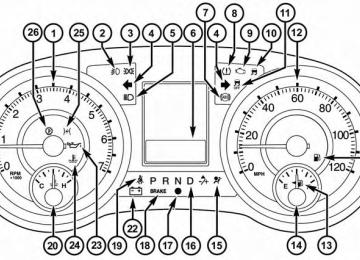
Loose Fuel Filler Cap Message If the vehicle diagnostic system determines that the fuel filler cap is loose, improperly installed, or damaged, a “gASCAP” message will display in the odometer or a “CHECK GASCAP” message will be displayed in the Electronic Vehicle Information Center (EVIC). Refer to
“Electronic Vehicle Information Center (EVIC)” in ”Un- derstanding Your Instrument Panel” for further informa- tion. Tighten the gas cap until a ⬙clicking⬙ sound is heard. This is an indication that the gas cap is properly tight- ened. Press the odometer reset button to turn the message off. If the problem persists, the message will appear the next time the vehicle is started. This might indicate a damaged cap. If the problem is detected twice in a row, the system will turn on the MIL. Resolving the problem will turn the MIL light off.
MAINTAINING YOUR VEHICLE 589
EMISSIONS INSPECTION AND MAINTENANCE PROGRAMS In some localities, it may be a legal requirement to pass an inspection of your vehicle’s emissions control system. Failure to pass could prevent vehicle registration.
For states that require an Inspection and Mainte- nance (I/M), this check verifies the “Malfunction Indicator Light (MIL)” is functioning and is not on when the engine is running, and that the OBD II system is ready for testing. Normally, the OBD II system will be ready. The OBD II system may not be ready if your vehicle was recently serviced, recently had a dead battery or a battery replace- ment. If the OBD II system should be determined not ready for the I/M test, your vehicle may fail the test.
590 MAINTAINING YOUR VEHICLE Your vehicle has a simple ignition key-actuated test, which you can use prior to going to the test station. To check if your vehicle’s OBD II system is ready, you must do the following: 1. Turn the ignition switch to the ON position, but do not
crank or start the engine.
2. If you crank or start the engine, you will have to start
this test over.
3. As soon as you turn the ignition switch to the ON position, you will see the MIL symbol come on as part of a normal bulb check.
happen:
4. Approximately 15 seconds later, one of two things will • The MIL will flash for about 10 seconds and then return to being fully illuminated until you turn OFF
the ignition or start the engine. This means that your vehicle’s OBD II system is not ready and you should not proceed to the I/M station. • The MIL will not flash at all and will remain fully illuminated until you turn OFF the ignition or start the engine. This means that your vehicle’s OBD II system is ready and you can proceed to the I/M station.
If your OBD II system is not ready, you should see your authorized dealer or repair facility. If your vehicle was recently serviced or had a battery failure or replacement, you may need to do nothing more than drive your vehicle as you normally would in order for your OBD II system to update. A recheck with the above test routine may then indicate that the system is now ready. Regardless of whether your vehicle’s OBD II system is ready or not, if the MIL is illuminated during normal vehicle operation you should have your vehicle serviced
before going to the I/M station. The I/M station can fail your vehicle because the MIL is on with the engine running.
REPLACEMENT PARTS Use of genuine MOPAR威 parts for normal/scheduled maintenance and repairs is highly recommended to en- sure the designed performance. Damage or failures caused by the use of non-MOPAR威 parts for maintenance and repairs will not be covered by the manufacturer’s warranty.
DEALER SERVICE Your authorized dealer has the qualified service person- nel, special tools, and equipment to perform all service operations in an expert manner. Service Manuals are available which include detailed service information for your vehicle. Refer to these Service Manuals before attempting any procedure yourself.
MAINTAINING YOUR VEHICLE 591
tampering with emissions control NOTE: Intentional systems may void your warranty and could result in civil penalties being assessed against you.WARNING!
You can be badly injured working on or around a motor vehicle. Only do service work for which you have the knowledge and the proper equipment. If you have any doubt about your ability to perform a service job, take your vehicle to a competent me- chanic.
MAINTENANCE PROCEDURES The pages that follow contain the required maintenance services determined by the engineers who designed your vehicle.
592 MAINTAINING YOUR VEHICLE Besides those maintenance items specified in the fixed maintenance schedule, there are other components which may require servicing or replacement in the future.
CAUTION!
• Failure to properly maintain your vehicle or per- form repairs and service when necessary could result in more costly repairs, damage to other components or negatively impact vehicle perfor- mance. Immediately have potential malfunctions examined by an authorized dealer or qualified repair center.
(Continued)
CAUTION! (Continued)
• Your vehicle has been built with improved fluids that protect the performance and durability of your vehicle and also allow extended maintenance inter- vals. Do not use chemical flushes in these compo- nents as the chemicals can damage your engine, transmission, power steering or air conditioning. Such damage is not covered by the New Vehicle Limited Warranty. If a flush is needed because of component malfunction, use only the specified fluid for the flushing procedure.
Engine Oil
Checking Oil Level To assure proper engine lubrication, the engine oil must be maintained at the correct level. Check the oil level at regular intervals, such as every fuel stop. The best time to
check the engine oil level is about five minutes after a fully warmed engine is shut OFF or before starting the engine after it has sat overnight. Checking the oil while the vehicle is on level ground will improve the accuracy of the oil level readings. Maintain the oil level between the MIN and MAX markings on the dipstick. Adding one quart of oil when the reading is at the MIN mark will result in a MAX reading on these engines.
CAUTION!
Overfilling or underfilling will cause oil aeration, or loss of oil pressure. This could damage your engine.
MAINTAINING YOUR VEHICLE 593
Change Engine Oil The oil change indicator system will remind you that it is time to take your vehicle in for scheduled maintenance. Refer to the “Maintenance Schedule” for further informa- tion. NOTE:Under no circumstances should oil change inter- vals exceed 10,000 miles (16,000 km) or twelve months, whichever occurs first.
Engine Oil Selection For best performance and maximum protection under all types of operating conditions, the manufacturer only recommends engine oils that are API Certified and meet the requirements of Chrysler Material Standard MS-6395.
594 MAINTAINING YOUR VEHICLE American Petroleum Institute (API) Engine Oil Identification Symbol
This symbol means that the oil has been certified by the American Petroleum Institute (API). The manufacturer only recommends API Certified engine oils.
CAUTION!
Do not use chemical flushes in your engine oil as the chemicals can damage your engine. Such damage is not covered by the New Vehicle Limited Warranty.
Engine Oil Viscosity – 3.6L Engine SAE 5W-20 engine oil is recommended for all operating temperatures. This engine oil improves low temperature starting and vehicle fuel economy. The engine oil filler cap also shows the recommended engine oil viscosity for your engine. For information on engine oil filler cap location, refer to the “Engine Com- partment” illustration in this section. Synthetic Engine Oils You may use synthetic engine oils provided the recom- mended oil quality requirements are met, and the recom- mended maintenance intervals for oil and filter changes are followed. Materials Added To Engine Oil The manufacturer strongly recommends against the ad- dition of any additives (other than leak detection dyes) to
the engine oil. Engine oil is an engineered product and its performance may be impaired by supplemental addi- tives. Disposing Of Used Engine Oil And Oil Filters Care should be taken in disposing of used engine oil and oil filters from your vehicle. Used oil and oil filters, indiscriminately discarded, can present a problem to the environment. Contact your authorized dealer, service station or governmental agency for advice on how and where used oil and oil filters can be safely discarded in your area. Engine Oil Filter The engine oil filter should be replaced with a new filter at every engine oil change. Engine Oil Filter Selection This manufacturer’s engines have a full-flow type oil filter. Use a filter of this type for replacement. The quality
MAINTAINING YOUR VEHICLE 595
of replacement filters varies considerably. Only high quality filters should be used to assure most efficient service. MOPAR威 engine oil filters are a high quality oil filter and are recommended. Engine Air Cleaner Filter Refer to the “Maintenance Schedule” for the proper maintenance intervals.WARNING!
The air induction system (air cleaner, hoses, etc.) can provide a measure of protection in the case of engine backfire. Do not remove the air induction system (air cleaner, hoses, etc.) unless such removal is necessary for repair or maintenance. Make sure that no one is near the engine compartment before starting the vehicle with the air induction system (air cleaner, hoses, etc.) removed. Failure to do so can result in serious personal injury.
596 MAINTAINING YOUR VEHICLE Engine Air Cleaner Filter Selection The quality of replacement engine air cleaner filters varies considerably. Only high quality filters should be used to assure most efficient service. MOPAR威 engine air cleaner filters are a high quality filter and are recom- mended. Exhaust System The best protection against carbon monoxide entry into the vehicle body is a properly maintained engine exhaust system. If you notice a change in the sound of the exhaust system; or if the exhaust fumes can be detected inside the vehicle; or when the underside or rear of the vehicle is damaged; have an authorized technician inspect the complete ex- haust system and adjacent body areas for broken, dam- aged, deteriorated, or mispositioned parts. Open seams or loose connections could permit exhaust fumes to seep into the passenger compartment. In addition, have the
exhaust system inspected each time the vehicle is raised for lubrication or oil change. Replace as required.
WARNING!
• Exhaust gases can injure or kill. They contain carbon monoxide (CO), which is colorless and odorless. Breathing it can make you unconscious and can eventually poison you. To avoid breathing CO, refer to “Safety Tips/Exhaust Gas” in “Things To Know Before Starting Your Vehicle” for further information. • A hot exhaust system can start a fire if you park over materials that can burn. Such materials might be grass or leaves coming into contact with your exhaust system. Do not park or operate your ve- hicle in areas where your exhaust system can con- tact anything that can burn.
CAUTION!
• The catalytic converter requires the use of un- leaded fuel only. Leaded gasoline will destroy the effectiveness of the catalyst as an emissions control device and may seriously reduce engine perfor- mance and cause serious damage to the engine. • Damage to the catalytic converter can result if your vehicle is not kept in proper operating condition. In the event of engine malfunction, particularly involving engine misfire or other apparent loss of performance, have your vehicle serviced promptly. Continued operation of your vehicle with a severe malfunction could cause the converter to overheat, resulting in possible damage to the converter and vehicle.
MAINTAINING YOUR VEHICLE 597
Under normal operating conditions, the catalytic con- verter will not require maintenance. However, it is im- portant to keep the engine properly tuned to assure proper catalyst operation and prevent possible catalyst damage. NOTE: Intentional systems can result against you. In unusual situations involving grossly malfunctioning engine operation, a scorching odor may suggest severe and abnormal catalyst overheating. If this occurs, stop the vehicle, turn off the engine and allow it to cool. Service, including a tune-up to manufacturer’s specifica- tions, should be obtained immediately.tampering with emissions control in civil penalties being assessed
598 MAINTAINING YOUR VEHICLE To minimize the possibility of catalytic converter dam- age: • Do not shut off the engine or interrupt the ignition, when the transmission is in gear and the vehicle is in motion. • Do not try to start the engine by pushing or towing the • Do not idle the engine with any spark plug wires disconnected or removed, such as when diagnostic testing, or for prolonged periods during very rough idle or malfunctioning operating conditions.
vehicle.
Maintenance-Free Battery Your vehicle is equipped with a maintenance-free battery. You will never have to add water, nor is periodic main- tenance required.
WARNING!
• Battery fluid is a corrosive acid solution and can burn or even blind you. Do not allow battery fluid to contact your eyes, skin, or clothing. Do not lean over a battery when attaching clamps. If acid splashes in eyes or on skin, flush the area imme- diately with large amounts of water. Refer to “Jump-Starting Procedures” in “What To Do In Emergencies” for further information. • Battery gas is flammable and explosive. Keep flame or sparks away from the battery. Do not use a booster battery or any other booster source with an output greater than 12 Volts. Do not allow cable clamps to touch each other. • Battery posts, terminals, and related accessories contain lead and lead compounds. Wash hands after handling.
CAUTION!
• It is essential when replacing the cables on the battery that the positive cable is attached to the positive post and the negative cable is attached to the negative post. Battery posts are marked positive (+) and negative (-) and are identified on the battery case. Cable clamps should be tight on the terminal posts and free of corrosion. • If a “fast charger” is used while the battery is in the vehicle, disconnect both vehicle battery cables be- fore connecting the charger to the battery. Do not use a “fast charger” to provide starting voltage.
MAINTAINING YOUR VEHICLE 599
Air Conditioner Maintenance For best possible performance, your air conditioner should be checked and serviced by an authorized dealer at the start of each warm season. This service should include cleaning of the condenser fins and a performance test. Drive belt tension should also be checked at this time.
CAUTION!
Do not use chemical flushes in your air conditioning system as the chemicals can damage your air condi- tioning components. Such damage is not covered by the New Vehicle Limited Warranty.
600 MAINTAINING YOUR VEHICLE
WARNING!
• Use only refrigerants and compressor lubricants approved by the manufacturer for your air condi- tioning system. Some unapproved refrigerants are flammable and can explode, injuring you. Other unapproved refrigerants or lubricants can cause the system to fail, requiring costly repairs. Refer to Warranty Information Book, located on the DVD, for further warranty information. • The air conditioning system contains refrigerant under high pressure. To avoid risk of personal injury or damage to the system, adding refrigerant or any repair requiring lines to be disconnected should be done by an experienced technician.
Refrigerant Recovery And Recycling R-134a Air Conditioning Refrigerant is a hydrofluoro- carbon (HFC) that is endorsed by the Environmental Protection Agency and is an ozone-saving product. How- ever, the manufacturer recommends that air conditioning service be performed by authorized dealer or other service facilities using recovery and recycling equipment. NOTE: Use only manufacturer approved A/C system sealers, stop leak products, seal conditioners, compressor oil, and refrigerants. A/C Air Filter Refer to the “Maintenance Schedule” for the proper maintenance intervals.
WARNING!
Do not remove the A/C air filter while the blower is operating or personal injury may result.
The A/C air filter is located in the fresh air inlet behind the glove box. Perform the following procedure to re- place the filter: 1. Open the glove compartment and remove all contents. 2. Push in on the sides of the glove compartment and
lower the door.
3. Pivot the glove compartment downward. 4. Disengage the two retaining tabs that secure the filter
cover to the HVAC housing, and remove the cover.
MAINTAINING YOUR VEHICLE 601
A/C Air Filter Replacement
5. Remove the A/C air filter by pulling it straight out of
the housing.
602 MAINTAINING YOUR VEHICLE 6. Install the A/C air filter with the arrow on the filter pointing toward the floor. When installing the filter cover, make sure the retaining tabs fully engage the cover.
CAUTION!
The A/C air filter is identified with an arrow to indicate airflow direction through the filter. Failure to properly install the filter will result in the need to replace it more often.
7. Rotate the glove compartment door back into position. Body Lubrication Locks and all body pivot points, including such items as seat tracks, door hinge pivot points and rollers, liftgate, tailgate, sliding doors and hood hinges, should be lubri- cated periodically with a lithium based grease, such as
MOPAR威 Spray White Lube to assure quiet, easy opera- tion and to protect against rust and wear. Prior to the application of any lubricant, the parts concerned should be wiped clean to remove dust and grit; after lubricating excess oil and grease should be removed. Particular attention should also be given to hood latching compo- nents to ensure proper function. When performing other underhood services, the hood latch, release mechanism and safety catch should be cleaned and lubricated. The external lock cylinders should be lubricated twice a year, preferably in the Fall and Spring. Apply a small amount of a high quality lubricant, such as MOPAR威 Lock Cylinder Lubricant directly into the lock cylinder. Windshield Wiper Blades Clean the rubber edges of the wiper blades and the windshield periodically with a sponge or soft cloth and a mild nonabrasive cleaner. This will remove accumula- tions of salt or road film.
Operation of the wipers on dry glass for long periods may cause deterioration of the wiper blades. Always use washer fluid when using the wipers to remove salt or dirt from a dry windshield. Avoid using the wiper blades to remove frost or ice from the windshield. Keep the blade rubber out of contact with petroleum products such as engine oil, gasoline, etc. NOTE: Life expectancy of wiper blades varies depend- ing on geographical area and frequency of use. Poor performance of blades may be present with chattering, marks, water lines or wet spots. If any of these conditions are present, clean the wiper blades or replace as neces- sary. Adding Washer Fluid The fluid reservoir for the windshield washers and the rear window washer is shared. It is located in the engine compartment and should be checked at regular intervals.
MAINTAINING YOUR VEHICLE 603
Fill the reservoir with windshield washer solvent (not radiator antifreeze) and operate the system for a few seconds to flush out any residual water. The washer fluid reservoir will hold a full gallon of fluid when the Low Washer Fluid Light illuminates.WARNING!
Commercially available windshield washer solvents are flammable. They could ignite and burn you. Care must be exercised when filling or working around the washer solution.
After the engine has warmed, operate the defroster for a few minutes to reduce the possibility of smearing or freezing the fluid on the cold windshield. MOPAR威 All Weather Windshield Washer Solution or equivalent, used with water as directed on the container, aids cleaning action, reduces the freezing point to avoid line clogging, and is not harmful to paint or trim.
604 MAINTAINING YOUR VEHICLE Cooling System
WARNING!
• When working near the radiator cooling fan, disconnect the fan motor lead or turn the ignition switch to the OFF position. The fan is temperature controlled and can start at anytime the ignition switch is in the ON position. • You or others can be badly burned by hot engine coolant (antifreeze) or steam from your radiator. If you see or hear steam coming from under the hood, do not open the hood until the radiator has had time to cool. Never try to open a cooling system pressure cap when the radiator is hot.
Coolant Checks Check the engine coolant (antifreeze) protection every 12
months (before the onset of freezing weather, whereapplicable). If the engine coolant (antifreeze) is dirty or rusty in appearance, the system should be drained, flushed and refilled with fresh coolant. Check the front of the A/C condenser for any accumulation of bugs, leaves, etc. If dirty, clean by gently spraying water from a garden hose vertically down the face of the condenser. Check the coolant recovery bottle tubing for brittle rub- ber, cracking , tears, cuts and tightness of the connection at the bottle and radiator. Inspect the entire system for leaks. With the engine at normal operating temperature (but not running), check the cooling system pressure cap for proper vacuum sealing by draining a small amount of engine coolant (antifreeze) from the radiator drain cock. If the cap is sealing properly, the engine coolant (anti- freeze) will begin to drain from the coolant recovery bottle. DO NOT REMOVE THE COOLANT PRESSURE CAP WHEN THE COOLING SYSTEM IS HOT.
Cooling System – Drain, Flush, And Refill If the engine coolant (antifreeze) is dirty or contains a considerable amount of sediment, clean and flush with a reliable cooling system cleaner. Follow with a thorough rinsing to remove all deposits and chemicals. Properly dispose of the old engine coolant (antifreeze) solution. Refer to the “Maintenance Schedule” for the proper maintenance intervals. Selection Of Coolant Refer to “Fluids, Lubricants, and Genuine Parts” in “Maintaining Your Vehicle” for further information.
MAINTAINING YOUR VEHICLE 605
CAUTION!
• Mixing of engine coolant (antifreeze) other than specified Organic Additive Technology (OAT) en- gine coolant (antifreeze), may result in engine damage and may decrease corrosion protection. Organic Additive Technology (OAT) engine cool- ant is different and should not be mixed with Hybrid Organic Additive Technology (HOAT) en- gine coolant (antifreeze). If a non-OAT engine coolant (antifreeze) is introduced into the cooling system in an emergency, it should be replaced with the specified engine coolant (antifreeze) as soon as possible.
(Continued)
606 MAINTAINING YOUR VEHICLE
CAUTION! (Continued)
• Do not use water alone or alcohol-based engine coolant (antifreeze) products. Do not use additional rust inhibitors or antirust products, as they may not be compatible with the radiator engine coolant and may plug the radiator. • This vehicle has not been designed for use with propylene glycol-based engine coolant (antifreeze). Use of propylene glycol-based engine coolant (an- tifreeze) is not recommended.
Adding Coolant Your vehicle has been built with an improved engine coolant (antifreeze) that allows extended maintenance intervals. This engine coolant (antifreeze) can be used up to ten years or 150,000 miles (240,000 km) before replace- ment. To prevent reducing this extended maintenance
period, it is important that you use the same engine coolant (antifreeze) throughout the life of your vehicle. Please review these recommendations for using Organic Additive Technology (OAT) engine coolant (antifreeze). When adding engine coolant (antifreeze): • We recommend using MOPAR威 Antifreeze/Coolant 10 Year/150,000 Mile Formula OAT (Organic Additive Technology). • Mix a minimum solution of 50% OAT engine coolant and distilled water. Use higher concentrations (not to exceed 70%) if temperatures below −34° F (−37° C) are anticipated. • Use only high purity water such as distilled or deion- ized water when mixing the water/engine coolant (antifreeze) solution. The use of lower quality water will reduce the amount of corrosion protection in the engine cooling system.
Please note that it is the owner’s responsibility to main- tain the proper level of protection against freezing ac- cording to the temperatures occurring in the area where the vehicle is operated. NOTE: Mixing engine coolant (antifreeze) types is not recommended and can result in cooling system damage. Drain, flush, and refill as soon as possible to avoid damage if coolant types are mixed in an emergency. Cooling System Pressure Cap The cap must be fully tightened to prevent loss of engine coolant (antifreeze), and to ensure that engine coolant (antifreeze) will return to the radiator from the coolant recovery tank. The cap should be inspected and cleaned if there is any accumulation of foreign material on the sealing surfaces.
MAINTAINING YOUR VEHICLE 607
WARNING!
• The warning words “DO NOT OPEN HOT” on the cooling system pressure cap are a safety precaution. Never add engine coolant (antifreeze) when the engine is overheated. Do not loosen or remove the cap to cool an overheated engine. Heat causes pressure to build up in the cooling system. To prevent scalding or injury, do not remove the pressure cap while the system is hot or under pressure. • Do not use a pressure cap other than the one specified for your vehicle. Personal injury or en- gine damage may result.
Disposal Of Used Engine Coolant Used ethylene glycol-based engine coolant (antifreeze) is a regulated substance requiring proper disposal. Check with your local authorities to determine the disposal
608 MAINTAINING YOUR VEHICLE rules for your community. To prevent ingestion by ani- mals or children, do not store ethylene glycol-based engine coolant in open containers or allow it to remain in puddles on the ground. If ingested by a child or pet, seek emergency assistance immediately. Clean up any ground spills immediately. Coolant Level The coolant bottle provides a quick visual method for determining that the coolant level is adequate. With the engine OFF and cold, the level of the engine coolant (antifreeze) in the bottle should be between the ranges indicated on the bottle. The radiator normally remains completely full, so there is no need to remove the radiator cap unless checking for engine coolant (antifreeze) freeze point or replacing cool- ant. Advise your service attendant of this. As long as the engine operating temperature is satisfactory, the coolant bottle need only be checked once a month.
When additional engine coolant (antifreeze) is needed to maintain the proper level, it should be added to the coolant bottle. Do not overfill. Points To Remember NOTE: When the vehicle is stopped after a few miles/ kilometers of operation, you may observe vapor coming from the front of the engine compartment. This is nor- mally a result of moisture from rain, snow, or high humidity accumulating on the radiator and being vapor- ized when the thermostat opens, allowing hot engine coolant (antifreeze) to enter the radiator. If an examination of your engine compartment shows no evidence of radiator or hose leaks, the vehicle may be safely driven. The vapor will soon dissipate. • Do not overfill the coolant expansion bottle.
• Check the coolant freeze point in the radiator and in the coolant expansion bottle. If engine coolant (anti- freeze) needs to be added, the contents of the coolant expansion bottle must also be protected against freezing. • If frequent engine coolant (antifreeze) additions are required, the cooling system should be pressure tested for leaks. • Maintain engine coolant (antifreeze) concentration at 50% OAT engine coolant (antifreeze) (minimum) and distilled water for proper corrosion protection of your engine which contains aluminum components. • Make sure that the coolant expansion bottle overflow • Keep the front of the radiator clean. If your vehicle is equipped with air conditioning, keep the front of the condenser clean.
hoses are not kinked or obstructed.
MAINTAINING YOUR VEHICLE 609
• Do not change the thermostat for Summer or Winter operation. If replacement is ever necessary, install ONLY the correct type thermostat. Other designs may in unsatisfactory engine coolant (antifreeze) result performance, poor gas mileage, and increased emissions.
Brake System In order to assure brake system performance, all brake system components should be inspected periodically. Refer to the “Maintenance Schedule” for the proper maintenance intervals.
610 MAINTAINING YOUR VEHICLE
WARNING!
Riding the brakes can lead to brake failure and possibly a collision. Driving with your foot resting or riding on the brake pedal can result in abnormally high brake temperatures, excessive lining wear, and possible brake damage. You would not have your full braking capacity in an emergency.
Master Cylinder – Brake Fluid Level Check The fluid level in the master cylinder should be checked when performing underhood services, or immediately if the “Brake System Warning Light” indicates system failure.
Clean the top of the master cylinder area before removing the cap. Add fluid to bring the level up to the top of the “FULL” mark on the side of the master cylinder reservoir. Overfilling of fluid is not recommended because it may cause leaking in the system. Add enough fluid to bring the level up to the require- ments described on the brake fluid reservoir. With disc brakes, fluid level can be expected to fall as the brake pads wear. However, low fluid level may be caused by a leak and a checkup may be needed. Use only manufacturer’s recommended brake fluid. Re- fer to “Fluids, Lubricants, and Genuine Parts” in “Main- taining Your Vehicle” for further information.
WARNING!
• Use only manufacturer’s recommended brake fluid. Refer to “Fluids, Lubricants, and Genuine Parts” in “Maintaining Your Vehicle” for further information. Using the wrong type of brake fluid can severely damage your brake system and/or impair its performance. The proper type of brake fluid for your vehicle is also identified on the original factory installed hydraulic master cylinder reservoir.
(Continued)
MAINTAINING YOUR VEHICLE 611
WARNING! (Continued)
• To avoid contamination from foreign matter or moisture, use only new brake fluid or fluid that has been in a tightly closed container. Keep the master cylinder reservoir cap secured at all times. Brake fluid in a open container absorbs moisture from the air resulting in a lower boiling point. This may cause it to boil unexpectedly during hard or pro- longed braking, resulting in sudden brake failure. This could result in a collision. • Overfilling the brake fluid reservoir can result in spilling brake fluid on hot engine parts, causing the brake fluid to catch fire. Brake fluid can also damage painted and vinyl surfaces, care should be taken to avoid its contact with these surfaces.
612 MAINTAINING YOUR VEHICLE
WARNING! (Continued)
• Do not allow petroleum based fluid to contaminate the brake fluid. Brake seal components could be damaged, causing partial or complete brake failure. This could result in a collision.
Automatic Transmission
Selection Of Lubricant It is important to use the proper transmission fluid to ensure optimum transmission performance and life. Use