- 2013 Chrysler TOWN and Country Owners Manuals
- Chrysler TOWN and Country Owners Manuals
- 2006 Chrysler TOWN and Country Owners Manuals
- Chrysler TOWN and Country Owners Manuals
- 2011 Chrysler TOWN and Country Owners Manuals
- Chrysler TOWN and Country Owners Manuals
- 2007 Chrysler TOWN and Country Owners Manuals
- Chrysler TOWN and Country Owners Manuals
- 2010 Chrysler TOWN and Country Owners Manuals
- Chrysler TOWN and Country Owners Manuals
- 2005 Chrysler TOWN and Country Owners Manuals
- Chrysler TOWN and Country Owners Manuals
- 2009 Chrysler TOWN and Country Owners Manuals
- Chrysler TOWN and Country Owners Manuals
- 2004 Chrysler TOWN and Country Owners Manuals
- Chrysler TOWN and Country Owners Manuals
- 2012 Chrysler TOWN and Country Owners Manuals
- Chrysler TOWN and Country Owners Manuals
- 2008 Chrysler TOWN and Country Owners Manuals
- Chrysler TOWN and Country Owners Manuals
- Download PDF Manual
-
Select Channel/Screen 1 And AUX 1 In The VES Column
Listen To An Audio Source On Channel 2 While A Video Is Playing On Channel 1
Ensure the Remote Control and Headphone switch is on Channel 2. Using The Remote Control 1. Press the MODE/SOURCE button on the Remote Control and the Mode Select Screen will display, unless a video is playing then only a small banner will appear on the bottom of the screen.2. While looking at the video screen, either press Up/ Down/Left/Right on the Remote Control to highlight the desired audio source or repeatedly press the MODE/SOURCE button on the remote until the de- sired audio source appears on the screen.
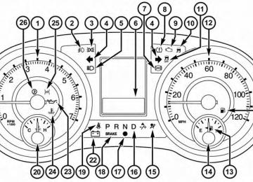
UNDERSTANDING YOUR INSTRUMENT PANEL 389
Select FM Mode On The VES Screen
Using The Touch-Screen Radio Controls 1. Press the MENU hard-key on the radio faceplate.
390 UNDERSTANDING YOUR INSTRUMENT PANEL 2. Touch the Rear VES soft-key to display the Rear VES Controls. If a channel list is displayed, press the HIDE LIST soft-key to display the Rear VES Controls screen.
3. To listen to an audio source on Channel 2 while a video is playing on Channel 1, touch the 2 soft-key and choose an audio source. To exit touch the back arrow soft-key at the top left of the left screen.
Rear VES Soft-Key
Select Channel/Screen 2 And HDD In The Media Column
Dual Video Screen
NOTE: Typically there are two different ways to operate the features of the Video Entertainment System (VES)™. • The Remote Control • The Touch-Screen Radio (If Equipped) Play A DVD Using The Touch-Screen Radio
1. Press the OPEN/CLOSE or LOAD hard-key on the
radio faceplate (Touch-Screen).
2. Insert the DVD with the label facing up. The radio automatically selects the appropriate mode after the disc is recognized and displays the menu screen or starts playing the first track.
UNDERSTANDING YOUR INSTRUMENT PANEL 391
3. To watch a DVD on Screen 1 for second row passen- gers, ensure the Remote Control and Headphone switch is on Channel 1.4. To watch a DVD on Screen 2 for third row passengers, ensure the Remote Control and Headphone switch is on Channel 2.
Using The Remote Control 1. Press the MODE/SOURCE button on the Remote
Control.
392 UNDERSTANDING YOUR INSTRUMENT PANEL 2. While looking at Screen 1 or 2, highlight DISC by either pressing Up/Down/Left/Right buttons or by repeatedly pressing the SOURCE button, then press ENTER/OK.
on the left side of the screen.
NOTE: • Channel/Screen 1 select mode information is shown • Channel/Screen 2 select mode information is shown • The VES™ will retain the last setting when turned off.
on the right side of the screen.
Using The Touch-Screen Radio Controls 1. Press the MENU hard-key on the radio faceplate. 2. Touch the Rear VES soft-key to display the Rear VES Controls. If a channel list is displayed, press the HIDE LIST soft-key to display the Rear VES Controls screen.
Select DISC Mode On The VES Screen
UNDERSTANDING YOUR INSTRUMENT PANEL 393
NOTE: • To view a DVD on the radio press the RADIO/MEDIA hard-key, on the radio faceplate, then touch the DISC tab soft-key and then the VIEW VIDEO soft-key. • Viewing a DVD on the Touch-Screen radio screen is not available in all states/provinces, and the vehicle must be stopped, and the shift lever must be in the PARK position for vehicles with automatic transmis- sion. In vehicles with manual transmission the parking brake must be engaged. • Touching the screen on a Touch-Screen radio while a DVD is playing brings up basic remote control func- tions for DVD play such as scene selection, Play, Pause, FF, RW, and Stop. Pressing the X in the upper corner will turn off the remote control screen functions.
Rear VES Soft-key
3. Touch the 1 or 2 soft-key and then the DISC soft-key in the MEDIA column. To exit touch the back arrow at the top left of the screen.
394 UNDERSTANDING YOUR INSTRUMENT PANEL Play A DVD Using The VES™ Player (If Equipped)
1. Insert the DVD with the label facing up. The VES™ player automatically selects the appropriate mode after the disc is recognized and starts playing the DVD.
NOTE: The VES™ player has basic DVD control func- tion such as Menu, Play, Pause, FF, RW and Stop 2. To watch a DVD on Screen 1 for second row passen- gers, ensure the Remote Control and Headphone switch is on Channel 1.
3. To watch a DVD on Screen 2 for third row passengers, ensure the Remote Control and Headphone switch is on Channel 2.
Using The Remote Control 1. Press the MODE/SOURCE button on the Remote
Control.
2. While looking at Screen 1 or 2, highlight VES DISC by either pressing Up/Down/Left/Right buttons or by repeatedly pressing the MODE/SOURCE button, then press ENTER/OK on the Remote Control.
Select VES DISC Mode On The VES Screen
on the left side of the screen.
NOTE: • Channel/Screen 1 select mode information is shown • Channel/Screen 2 select mode information is shown • The VES™ will retain the last setting when turned off.
on the right side of the screen.
UNDERSTANDING YOUR INSTRUMENT PANEL 395
Using The Touch-Screen Radio Controls 1. Press the MENU hard-key on the radio faceplate. 2. Touch the Rear VES soft-key to display the Rear VES Controls. If a channel list is displayed, touch the HIDE LIST soft-key to display the Rear VES Controls screen.
Rear VES Soft-key
396 UNDERSTANDING YOUR INSTRUMENT PANEL 3. Touch the 1 or 2 soft-key and then the DISC soft-key in the VES column. To exit touch the back arrow soft-key at the top left of the screen.
Select Channel/Screen 1 And DISC In The VES Column
NOTE: • To view a DVD on the radio press the RADIO/MEDIA hard-key, on the radio faceplate, then touch the DISC tab soft-key and then the VIEW VIDEO soft-key. • Viewing a DVD on the Touch-Screen radio screen is not available in all states/provinces, and the vehicle must be stopped, and the shift lever must be in the PARK position for vehicles with automatic transmis- sion. In vehicles with manual transmission the parking brake must be engaged.
Listen To An Audio Source While A Video Is Playing Ensure the Remote Control and Headphone switch are on the same channel. If watching a video on Screen 1
(second row), then Channel 2 could be used for audio. If watching a video on Screen 2 (third row), then Channel 1
could be used for audio.Using The Remote Control 1. Press the MODE/SOURCE button on the Remote Control and the Mode Select Screen will display, unless a video is playing then only a small banner will appear on the bottom of the screen.
2. While looking at the video screen, either press Up/ Down/Left/Right on the Remote Control to highlight the desired audio source or repeatedly press the MODE/SOURCE button on the remote until the de- sired audio source appears on the screen.
UNDERSTANDING YOUR INSTRUMENT PANEL 397
Select FM Mode On The VES Screen
Using The Touch-Screen Radio Controls 1. Press the MENU hard-key on the radio faceplate.
398 UNDERSTANDING YOUR INSTRUMENT PANEL 2. Touch the Rear VES soft-key to display the Rear VES Controls. If a channel list is displayed, press the HIDE LIST soft-key to display the Rear VES Controls screen.
3. To listen to an audio source on Channel 2 while a video is playing on Channel 1, touch the 2 soft-key and choose an audio source. To exit touch the back arrow soft-key at the top left of the left screen.
Rear VES Soft-Key
Select Channel/Screen 2 And HDD In The Media Column
lower and swivel to face forward.
Third Row Swivel Screen (If Equipped) • The third row screen or Screen 2 has the ability to • While the swivel screen is facing forward, the second row screen or Screen 1 must be fully open in order for the swivel screen (Screen 2) to work.
UNDERSTANDING YOUR INSTRUMENT PANEL 399
Blu-Ray Discs.
and video simultaneously.
Important Notes For Dual Video Screen System • VES is able to transmit two channels of stereo audio • The Blu-Ray DVD Player can play CDs, DVDs and • The DVD Player can play CDs and DVDs. • In split screen mode the left side equates to Channel 1
• Selecting a video source on Channel 1, the video source will display on the second row screen or Screen 1 and can be heard on Channel 1. • Selecting a video source on Channel 2, the video source will display on the third row screen or Screen 2
and can be heard on Channel 2.and the right side equates to Channel 2.
400 UNDERSTANDING YOUR INSTRUMENT PANEL
• The 2nd row screen and 3rd row screen of the Video Entertainment System can play two separate discs by utilizing the touch-screen radio DVD player and Blu- Ray Disc Player. • Audio can be heard through the headphones even
when the screen(s) are closed.
VES Remote Control – If Equipped
Remote Control
Controls And Indicators 1. Power – Turns the screen and wireless headphone transmitter for the selected Channel on or off. To hear audio while the screen is closed, press the Power button to turn the headphone transmitter on.
2. Channel Selector Indicators – When a button is pressed, the currently affected channel or channel button is illuminated momentarily.
3. Light – Turns the remote control backlighting on or off. The remote backlighting turns off automatically after five seconds.
4. Channel/Screen Selector Switch - Indicates which channel is being controlled by the remote control. When the selector switch is in the Channel 1 position, the remote controls the functionality of headphone Channel 1 (right side of the screen). When the selector
UNDERSTANDING YOUR INSTRUMENT PANEL 401
switch is in the Channel 2, position the remote controls the functionality of headphone Channel 2 (left side of the screen).5. 䉴䉴 – In radio modes, press to seek the next tunable station. In disc modes, press and hold to fast forward through the current audio track or video chapter. In menu modes use to navigate in the menu.
6. 䉲 / Prev – In radio modes, press to select to the previous station. In disc modes, press to advance to the start of the current or previous audio track or video chapter. In menu modes, use to navigate in the menu.
7. POP UP/MENU – Press to return to the main menu of a DVD disc, to select a satellite audio channel from the Station list, or (SCAN/ RANDOM for a CD).
select playback modes
402 UNDERSTANDING YOUR INSTRUMENT PANEL 8. 䉴 / 㥋 (Play/Pause) – Begin/resume or pause disc play. 9. ▪ (Stop) – Stops disc play 10. PROG Up/Down / Rewind/skip back and fast fwd/ skip forward – When listening to a radio mode, pressing PROG Up selects the next preset and press- ing PROG Down selects the previous preset stored in the radio. When listening to compressed audio on a data disc, PROG Up selects the next directory and PROG Down selects the previous directory. When listening to a disc in a radio with a multiple-disc changer, PROG Up selects the next disc and PROG Down selects the previous disc.
11. MUTE – Press to mute the headphone audio output
for the selected channel.
12. SLOW – If Equipped – Press to slow playback of a
DVD disc. Press play (䉴) to resume normal play.
13. STATUS – If Equipped – Press to display the current
status.
14. MODE/SOURCE – Press to change the mode of the selected channel. See the Mode Selection section of this manual for details on changing modes.
15. SETUP – When in a video mode, press the SETUP button to access the display settings (see the display settings section) to access the DVD setup menu, select the menu button on the radio. When a disc is loaded in the DVD player (if equipped) and the VES™ mode is selected and the disc is stopped, press the SETUP button to access the DVD Setup menu. (see the DVD Setup Menu of this manual.)
16. BACK – When navigating in menu mode, press to return to the previous screen. When navigating a DVDs disc menu, the operation depends on the disc’s contents.
17. 䉳䉳 – In radio modes, press to seek to the previous tunable station. In disc modes, press and hold to fast rewind through the current audio track or video chapter. In menu modes use to navigate in the menu. 18. ENTER/OK – Press to select the highlighted option
in a menu.
19. 䉱 / NEXT – In radio modes, press to select to the next station. In disc modes, press to advance to the next audio track or video chapter. In menu modes, use to navigate in the menu.
Remote Control Storage The video screen(s) come with a built in storage compart- ment for the remote control which is accessible when the screen is opened. To remove the remote, use your index finger to pull and rotate the remote towards you. Do not try to pull the remote straight down as it will be very difficult to remove. To return the remote back into its
UNDERSTANDING YOUR INSTRUMENT PANEL 403
storage area, insert one long edge of the remote into the two retaining clips first, and then rotate the remote back up into the other two retaining clips until it snaps back into position.The Remote Control Storage
404 UNDERSTANDING YOUR INSTRUMENT PANEL Locking The Remote Control All remote control functionality can be disabled as a parental control feature. • To disable the Remote Control from making any changes, press the Video Lock button on the DVD player (if equipped). If the vehicle is not equipped with a DVD player, follow the radio’s instructions to turn Video Lock on. The radio and the video screen(s) indicate when Video Lock is active. • Pressing the Video Lock again or turning the ignition OFF turns Video Lock OFF and allows remote control operation of the VES™.
Replacing The Remote Control Batteries The remote control requires two AAA batteries for op- eration. To replace the batteries: • Locate the battery compartment on the back of the
remote, then slide the battery cover downward.
• Replace the batteries, making sure to orient them according to the polarity diagram shown. • Replace the battery compartment cover. Headphones Operation The headphones receive two separate channels of audio using an infrared transmitter from the video screen. Front seat occupants receive some headphone audio coverage to allow them to adjust the headphone volume for the young rear seat occupants that may not be able to do so for themselves. If no audio is heard after increasing the volume control, verify that the screen is turned on and in the down position and that the channel is not muted and the headphone channel selector switch is on the desired channel. If audio is still not heard, check that fully charged batteries are installed in the headphones.
UNDERSTANDING YOUR INSTRUMENT PANEL 405
NOTE: The rear video system must be turned on before sound can be heard from the headphones. To conserve battery life, the headphones will automatically turn off approximately three minutes after the rear video system is turned off. Changing the Audio Mode for Headphones 1. Ensure the Remote Control channel/screen selector switch is in the same position as the headphone selector switch.NOTE: • When both switches are on Channel 1, the Remote is controlling Channel 1 and the headphones are tuned to the audio of the VES™ Channel 1. • When both switches are on Channel 2, the Remote is controlling Channel 2 and the headphones are tuned to the audio of the VES™ Channel 2.
1. Volume Control 2. Power Button 3. Channel Selection Switch 4. Power Indicator Controls The headphone power indicator and controls are located on the right ear cup.
406 UNDERSTANDING YOUR INSTRUMENT PANEL 2. Press the MODE/SOURCE button on the remote
control.
3. If the video screen is displaying a video source (such as a DVD Video), pressing DISPLAY shows the status on a popup banner at the bottom of the screen. Pressing the MODE/SOURCE button will advance to the next mode. When the mode is in an audio only source (such as FM), the Mode Selection menu appears on screen.
4. When the Mode Selection menu appears on screen, use the cursor buttons on the remote control to navi- gate to the available modes and press the OK button to select the new mode.
5. To cancel out of the Mode Selection menu, press the
BACK button on the remote control.
Replacing The Headphone Batteries Each set of headphones requires two AAA batteries for operation. To replace the batteries: • Locate the battery compartment on the left ear cup of the headphones, and then slide the battery cover downward. • Replace the batteries, making sure to orient them according to the polarity diagram shown. • Replace the battery compartment cover. Unwired姞 Stereo Headphone Lifetime Limited Warranty Who Does This Warranty Cover? This warranty covers the initial user or purchaser (⬙you⬙ or ⬙your⬙) of this particular Unwired Technology LLC (⬙Unwired⬙) wire- less headphone (⬙Product⬙). The warranty is not transfer- able.
How Long Does the Coverage Last? This warranty lasts as long as you own the Product. What Does This Warranty Cover? Except as specified below, this warranty covers any Product that in normal use is defective in workmanship or materials. What Does This Warranty Not Cover? This warranty does not cover any damage or defect that results from misuse, abuse or modification of the Product other than by Unwired. Foam earpieces, which will wear over time through normal use, are specifically not covered (replace- ment foam is available for a nominal charge). UNWIRED TECHNOLOGY IS NOT LIABLE FOR ANY INJURIES OR DAMAGES TO PERSONS OR PROPERTY RESULT- ING FROM THE USE OF, OR ANY FAILURE OR DE- FECT IN, THE PRODUCT, NOR IS UNWIRED LIABLE FOR ANY GENERAL, SPECIAL, DIRECT, INDIRECT, INCIDENTAL, CONSEQUENTIAL, EXEMPLARY, PU- NITIVE OR OTHER DAMAGES OF ANY KIND OR NATURE WHATSOEVER. Some states and jurisdictions
UNDERSTANDING YOUR INSTRUMENT PANEL 407
may not allow the exclusion or limitation of incidental or consequential damages, so the above limitation may not apply to you. This warranty gives you specific legal rights. You may also have other rights, which vary from jurisdiction to jurisdiction. What Will Unwired威 Do? Unwired威, at its option, will repair or replace any defective Product. Unwired威 re- serves the right to replace any discontinued Product with a comparable model. THIS WARRANTY IS THE SOLE WARRANTY FOR THIS PRODUCT, SETS FORTH YOUR EXCLUSIVE REMEDY REGARDING DEFECTIVE PRODUCTS, AND IS IN LIEU OF ALL OTHER WAR- RANTIES (EXPRESS OR IMPLIED), INCLUDING ANY WARRANTY OR MERCHANTABILITY OR FITNESS FOR A PARTICULAR PURPOSE. If you have any questions or comments regarding your Unwired威 wireless headphones, please phone 1-888-293- 3332 or email [email protected].408 UNDERSTANDING YOUR INSTRUMENT PANEL You may register your Unwired威 wireless headphones online at www.unwiredtechnology.com or by phone at 1-888-293-3332. System Information
Shared Modes This allows the VES™ to output radio sources to the headphones and the radio to output VES™ sources to the vehicle speakers. When the radio and VES™ channel 1 or 2 are in the same (shared) mode, a VES™ icon will be visible on the radio’s display for that channel, and the shared icon will be visible on the VES™ screen. When in shared mode, the same audio source is heard in the shared headphone channel 1 or channel 2. If the radio functions (FM, AM, or SAT) are in the shared mode with the VES™, only the radio is able to control the radio functions. In this case, VES™ can share the radio mode, but not change stations until the radio mode is
changed to a mode that is different from the VES™ selected radio mode. When shared, the radio has priority over the VES™ or all radio modes (FM, AM, and SAT). The VES™ has the ability to switch tuner (AM/FM), SEEK, SCAN, TUNE, and recall presets in radio modes as long as it is not in shared mode. When in shared disc mode both the radio and the VES™ have control of the video functions. The VES™ has the ability to control the following video modes: 1. CD: Ability to Fast Forward, Rewind, Scan, and Track
Up/Down.
2. CD Changer (in radio): Ability to Disk Up/Down and program all listed CD controls (Fast Forward, Rewind, Scan, and Track Up/Down).
The VES™ can even control radio modes or video modes while the radio is turned off. The VES™ can access the radio modes or disc modes by navigating to those modes on the VES™ and activating a radio mode or disc mode.
UNDERSTANDING YOUR INSTRUMENT PANEL 409
4. Channel 2 Mode 5. Channel 2 Shared Status 6. Channel 2 Audio Only/Mute 7. Channel 1 ENTER/OK Button Action 8. Channel 2 ENTER/OK Button Action 9. Clock 10. Video Lock 11. Not Available / Error 12. Disc Changer Status
Information Mode Display
Information Mode Video Screen Display
1. Channel 1 Mode 2. Channel 1 Shared Status 3. Channel 1 Audio Only/Mute
410 UNDERSTANDING YOUR INSTRUMENT PANEL Numeric Keypad Menu
Numeric Keypad Menu
When the display for either Channel 1 or Channel 2
shows DIRECT TUNE, pressing the remote control’s OK button activates a numeric keypad menu. This screen makes it easy to enter a specific tuner frequency, satellite channel, or track number. To enter the desired digit: 1. Press the remote control’s navigation buttons (䉱, 䉲,䉴, 䉳) to navigate to the desired digit.
2. When the digit is highlighted, press the remote con- trol’s ENTER/OK button to select the digit. Repeat these steps until all digits are entered.
3. To delete the last digit, navigate to the Del button and
press the remote control’s ENTER/OK button.
4. After all of the digits are entered, navigate to the Go button and press the remote control’s ENTER/OK button.
Station List Menu When listening to Satellite audio, pressing the remote control’s POP UP/MENU button displays a list of all available channels. Navigate this list using the remote control’s navigation buttons (䉱, 䉲) to find the desired station, press the remote control’s ENTER/OK button to tune to that station. To jump through the list more quickly, navigate to the Page Up and Page Down icons on the screen.
UNDERSTANDING YOUR INSTRUMENT PANEL 411
Disc Menu
Disc Menu For CDs
When listening to a CD Audio or CD Data disc, pressing the remote control’s POP UP/MENU button displays a
412 UNDERSTANDING YOUR INSTRUMENT PANEL list of all commands which control playback of the disc. Using the options you can activate or cancel Scan play and Random play. Display Settings
Video Screen Display Settings
When watching a video source (DVD Video with the disc in Play mode, Aux Video, etc.), pressing the remote control’s SETUP button activates the Display Settings menu. These settings control the appearance of the video on the screen. The factory default settings are already set for optimum viewing, so there is no need to change these settings under normal circumstances. To change the settings, press the remote control’s navi- gation buttons (䉱, 䉲) to select an item, then press the remote control’s navigation buttons (䉴, 䉳) to change the value for the currently selected item. To reset all values back to the original settings, select the Default Settings menu option and press the remote control’s ENTER/OK button. Disc Features control the remote DVD player’s (if equipped) settings of DVD being watched in the remote player.
Listening To Audio With The Screen Closed To listen to only audio portion of the channel with the screen closed: • Set the audio to the desired source and channel. • Close the video screen. • To change the current audio mode, press the remote control’s MODE/SOURCE button. This will automati- cally select the next available audio mode without using the Mode/Source Select menu. • When the screen is reopened, the video screen will automatically turn back on and show the appropriate display menu or media.
If the screen is closed and there is no audio heard, verify that the headphones are turned on (the ON indicator is illuminated) and the headphone selector switch is on the
UNDERSTANDING YOUR INSTRUMENT PANEL 413
desired channel. If the headphones are turned on, press the remote control’s power button to turn audio on. If audio is still not heard, check that fully charged batteries are installed in the headphones. Disc Formats The VES™ DVD player is capable of playing the follow- ing types of discs (12 mm or 8 mm diameter): • DVD-Video discs (MPEG-2 video compression) (see • DVD-Audio discs (2 channel audio output only) • Audio Compact Discs (CDs) • CD Data discs with MP3 and WMA compressed audio • Video CDs (MPEG-1 video compression)notes about DVD Region Codes)
format files
414 UNDERSTANDING YOUR INSTRUMENT PANEL DVD Region Codes The VES™ DVD player and many DVD discs are coded by geographic region. These region codes must match in order for the disc to play. If the region code for the DVD disc does not match the region code for the player, the disc will not play and will be ejected. DVD Audio Support When a DVD-Audio disc is inserted in the VES™ DVD player, the DVD-Audio title on the disc is played by default (most DVD-Audio discs also have a Video title, but the Video title is ignored). All multi-channel program material is automatically mixed down to two channels, which may result in a lowered apparent volume level. If you increase the volume level to account for this change in level, remember to lower the volume before changing the disc or to another mode.
Recorded Discs The VES™ DVD player will play CD-R and CD-RW discs recorded in CD-Audio or Video-CD format, or as a CD-ROM containing MP3 or WMA files. The player will also play DVD-Video content recorded to a DVD-R or DVD-RW disc. DVD-ROM discs (either pressed or re- corded) are not supported. If you record a disc using a personal computer, there may be cases where the VES™ DVD player may not be able to play some or the entire disc, even if it is recorded in a compatible format and is playable on other players. To help avoid playback problems, use the following guide- lines when recording discs. • Open sessions are ignored. Only sessions that are
closed are playable.
• For multi-session CDs that contain only multiple CD- Audio sessions, the player will renumber the tracks so each track number is unique. • For CD Data (or CD-ROM) discs, always use the ISO-9660 (Level 1 or Level 2), Joliet, or Romeo format. Other formats (such as UDF, HFS, or others) are not supported. • The player recognizes a maximum of 512 files and 99
• Mixed media recordable DVD formats will only playfolders per CD-R and CD-RW disc.
the Video_TS portion of the disc.
If you are still having trouble writing a disc that is playable in the VES™ DVD player, check with the disc recording software publisher for more information about burning playable discs. The recommended method for labeling recordable discs (CD-R, CD-RW, and DVD-R) is with a permanent marker.
UNDERSTANDING YOUR INSTRUMENT PANEL 415
Do not use adhesive labels as they may separate from the disc, become stuck, and cause permanent damage to the DVD player. Compressed Audio Files (MP3 and WMA) The DVD player is capable of playing MP3 (MPEG-1
Audio Layer 3) and WMA (Windows Media Audio) files from a CD Data disc (usually a CD-R or CD-RW). • The DVD player always uses the file extension to determine the audio format, so MP3 files must always end with the extension ⬙.mp3⬙ or ⬙.MP3⬙ and WMA files must always end with the extension ⬙.wma⬙ or ⬙.WMA⬙. To prevent incorrect playback, do not use these extensions for any other types of files. • For MP3 files, only version 1 ID3 tag data (such asartist name, track title, album, etc.) are supported.
416 UNDERSTANDING YOUR INSTRUMENT PANEL
• Any file that is copy protected (such as those down- loaded from many online music stores) will not play. The DVD player will automatically skip the file and begin playing the next available file. • Other compression formats such as AAC, MP3 Pro, Ogg Vorbis, and ATRAC3 will not play. The DVD player will automatically skip the file and begin play- ing the next available file. • If you are creating your own files, the recommended fixed bit rate for MP3 files is between 96 and 192Kbps and the recommended fixed bit rate for WMA files is between 64 and 192Kbps. Variable bit rates are also the recommended supported. For both formats, sample rate is either 44.1kHz or 48kHz. • To change the current file, use the remote control’s or DVD player’s 䉱 button to advance to the next file, or the 䉲 button to return to the start of the current or previous file.
• To change the current directory, use the remote con- trol’s PROG UP and Down buttons or Rewind/skip back and fast fwd/skip forward.
Disc Errors If the DVD player is unable to read the disc, a ⬙Disc Error⬙ message is displayed on the VES™ and Radio displays and the disc is automatically ejected. A dirty, damaged, or incompatible disc format are all potential causes for a ⬙Disc Error⬙ message. If a disc has a damaged track which results in audible or visible errors that persists for 2.0 seconds, the DVD player will attempt to continue playing the disc by skipping forward 1.0 to 3.0 seconds at a time. If the end of the disc is reached, the DVD player will return to the beginning of the disc and attempt to play the start of the first track.
The DVD player may shut down during extremely hot conditions, such as when the vehicle’s interior tempera- ture is above 120°F. When this occurs, the DVD player will display ⬙VES High Temp⬙ and will shut off the VES™ displays until a safe temperature is reached. This shut- down is necessary to protect the optics of the DVD player.
UNDERSTANDING YOUR INSTRUMENT PANEL 417
Display Other Language Setup
DVD Player Language Menu
418 UNDERSTANDING YOUR INSTRUMENT PANEL All of the Language settings have a special ⬙Other⬙ setting to accommodate languages other than Japanese or Eng- lish. These languages are selected using a special four- digit code. To enter a new language code, activate the DVD Setup Menu. To enter DVD Setup Menu stop the DVD, enter radio disc mode, then DVD setup and follow these additional instructions: • Using the remote control Up and Down cursor but- tons, highlight the Language item you want to edit, and then press the remote control ENTER/OK button. • Using the remote control Down cursor button, select the ⬙Other⬙ setting, then press the remote control’s Right cursor button to begin editing the setting. • Using the remote control Up and Down cursor but- tons, select a digit for the current position. After
selecting the digit, press the remote control’s Right cursor button to select the next digit. Repeat this digit selection sequence for all four digits. • When the entire four-digit code is entered, press the remote control’s ENTER/OK button. If the language code is not valid, the numbers all change back to ⬙夡⬙. If the digits are visible after this step, then the lan- guage code is valid.
Here is an abbreviated list of language codes. For more language codes, please contact the dealer where the vehicle was purchased.
Language Dutch German Portuguese
Code 2311
1304
2519Language French Italian Spanish
Code 1517
1819
1418Rating and Password Setup The Rating and Password settings work together to control the types of DVDs that your family watches. Most DVD- Video discs have a rating (from 1 to 8) assigned to them where lower numbers are designated for all audiences and higher numbers are designated for more adult audiences. When a DVD-Video disc is loaded, its rating is compared to the setting in the DVD player. If the rating of the disc is higher than the setting in the player, a Password screen is displayed. In order to watch the disc, the rear passen- ger must enter the correct password using the password entry method described below. To play all discs without requiring a password, set the DVD player’s rating to Level 8. Setting the rating to Level 1 always requires the password to play any DVD disc. Not all DVD discs encode a Rating, so it is still possible that discs designed for adult audiences can still play without requiring a password.
UNDERSTANDING YOUR INSTRUMENT PANEL 419
The default rating is Level 8 (play all discs without a password) and the default password is 0000.DVD Password Entry
tons, select the Rating tab.
remote control’s ENTER/OK button.
420 UNDERSTANDING YOUR INSTRUMENT PANEL To set the password, activate the DVD Setup Menu and follow these additional instructions: • Using the remote control Left and Right cursor but- • Highlight ⬙Change Password⬙, and then press the • Enter the current password. Select a digit, use the remote control Up and Down cursor buttons to set the value for the current digit, and then press the remote control’s Right cursor button to select the next digit. Repeat this digit selection sequence for all four digits. • After the four-digit password is entered, press the remote control’s ENTER/OK button. If the password is correct, the set password screen is displayed. • Using the remote control’s Up and Down cursor buttons to set the value for the current digit and the remote control’s Right cursor button to select digits, enter the new password.
• After the four-digit password is entered, press the remote
control’s ENTER/OK button to accept the change.
DVD Player Level Menu
control’s ENTER/OK button.
buttons, select the Rating tab.
To set the rating, activate the DVD Setup Menu and follow these additional instructions: • Using the remote control’s Left and Right cursor • Highlight ⬙Change Rating⬙, and then press the remote • Enter the current password. Select a digit, use the remote control’s Up and Down cursor buttons to set the value for the current digit, and then press the remote control’s Right cursor button to select the next digit. Repeat this digit selection sequence for all four digits. • After the four-digit password is entered, press the remote control’s ENTER/OK button. If the password is correct, the Rating Level menu is displayed.
UNDERSTANDING YOUR INSTRUMENT PANEL 421
• Using the remote control’s Up and Down cursor buttons, select the new rating level, and then press the remote control’s ENTER/OK button to accept the change.
Product Agreement This product incorporates copyright protection technol- ogy that is protected by U.S. patents and other intellec- tual property rights. Use of this copyright protection technology must be authorized by Macrovision, and is intended for home or other limited viewing uses other- wise authorized by Macrovision. Reverse engineering or disassembly is prohibited.
Dolby威 Digital and MLP Lossless Manufactured under license from Dolby Laboratories. ⬙Dolby⬙, ⬙MLP Lossless⬙, and the double-D symbol are trademarks of Dolby Laboratories. Confidential unpublished works. Copyright 1992-1997 Dolby Laboratories. All right reserved.
422 UNDERSTANDING YOUR INSTRUMENT PANEL General Information This system complies with Part 15 of the FCC Operation is subject to the following two conditions: 1. This device may not cause harmful interference. 2. This device must accept any interference received, including interference that may cause undesired op- eration.
STEERING WHEEL AUDIO CONTROLS — IF EQUIPPED
Remote Sound System Controls (Back View Of Steering Wheel)
The remote sound system controls are located on the rear surface of the steering wheel, at the three and nine o’clock positions. The right-hand rocker switch has a pushbutton in the center, and controls the volume and mode of the sound system. Pressing the top of the rocker switch will increase the volume. Pressing the bottom of the rocker switch will decrease the volume. Pressing the center button changes the operation of the radio from AM to FM, or to CD mode, depending on which radio is in the vehicle. The left-hand rocker switch has a pushbutton in the center. The function of the left-hand switch is different, depending on which mode you are in. The following describes the left-hand rocker switch op- eration in each mode.
UNDERSTANDING YOUR INSTRUMENT PANEL 423
Radio Operation Pressing the top of the switch will SEEK up for the next listenable station, and pressing the bottom of the switch will SEEK down for the next listenable station. The button located in the center of the left-hand switch will tune to the next preset station that you have pro- grammed in the radio preset pushbutton. CD Player Pressing the top of the switch once will go to the next track on the CD. Pressing the bottom of the switch once will go to the beginning of the current track, or to the beginning of the previous track if it is within one second after the current track begins to play. If you press the switch up or down twice it plays the second track; three times, it will play the third, etc. The button in the center of the left-hand switch has no function in this mode.
424 UNDERSTANDING YOUR INSTRUMENT PANEL CD/DVD DISC MAINTENANCE To keep a CD/DVD in good condition, take the following precautions: 1. Handle the disc by its edge; avoid touching the
surface.
2. If the disc is stained, clean the surface with a soft cloth,
wiping from center to edge.
3. Do not apply paper or tape to the disc; avoid scratch-
ing the disc.
4. Do not use solvents such as benzene, thinner, cleaners,
or anti-static sprays.
5. Store the disc in its case after playing. 6. Do not expose the disc to direct sunlight. 7. Do not store the disc where temperatures may become
too high.
NOTE: If you experience difficulty in playing a particu- lar disc, it may be damaged (i.e., scratched, reflective coating removed, a hair, moisture or dew on the disc) oversized, or have protection encoding. Try a known good disc before considering disc player service.
RADIO OPERATION AND MOBILE PHONES Under certain conditions, the mobile phone being on in your vehicle can cause erratic or noisy performance from your radio. This condition may be lessened or eliminated by relocating the mobile phone antenna. This condition is not harmful to the radio. If your radio performance does not satisfactorily “clear” by the repositioning of the antenna, it is recommended that the radio volume be turned down or off during mobile phone operation when not using Uconnect威 (if equipped).
CLIMATE CONTROLS The Climate Control system allows you to regulate the temperature, amount, and direction of air circulating throughout the vehicle. The controls are located on the instrument panel, below the radio. Manual Heating And Air Conditioning System — If Equipped The controls for the manual system in this vehicle contain a series of outer rotary dials and inner push knobs. These comfort controls can be set to obtain desired interior conditions.
UNDERSTANDING YOUR INSTRUMENT PANEL 425
With the Three-Zone Temperature Control system, each front seat occupant can independently control the Heat- ing, Ventilation, and Air Conditioning operations coming from the outlets on their side of the vehicle. The primary control for the rear blower is on the front climate control unit located on the instrument panel. When the front control is in any position other than rear, the front control operates all the rear functions.426 UNDERSTANDING YOUR INSTRUMENT PANEL The rear airflow modes will mirror the front unit opera- tion. Rear Panel mode is automatically selected when the front control is in the Panel mode. When the front unit is in Bi-Level mode, airflow will be emitted from both the upper and lower rear outlets. When the front control is in Floor, Defrost, or Mix modes, airflow will be directed out of the rear floor outlets.
Manual Temperature Control
1. Left Front Temperature Control • Provides left front seat occupant with independent temperature control. Turn left for cooler or right for warmer temperature settings.
2. Rear Blower Control — If Equipped • Use this control to regulate the amount of air forced through the rear system in any mode you select. The rear blower speed increases as you move the control to the right from the “O” (Off) position. There are seven blower speeds. To allow the rear overhead control, turn blower knob fully to the left, past The ⬙O⬙ off position into the “REAR” control position.
3. Front Blower Control • Use this control to regulate the amount of air forced through the system in any mode you select. The blower speed increases as you move the control to the right from the “O” (Off) position. There are seven blower speeds.
UNDERSTANDING YOUR INSTRUMENT PANEL 427
NOTE: For vehicles equipped with Remote Start, the climate controls will not function during Remote Start operation if the blower control is left in the “O” (Off) position. Blower control should be left in the ⬙ON⬙ position to allow the climate control to either warm or cool the vehicle. 4. Rear Temperature Control — If Equipped • Provides temperature control for the rear cabin. Turn left for cooler or right for warmer temperature settings in the rear cabin.5. Right Front Temperature Control • Provides right front seat occupant with independent temperature control. Turn left for cooler or right for warmer temperature settings.
6. Mix Mode
Air is directed through the floor, defrost and side window demist outlets. This setting works best in
428 UNDERSTANDING YOUR INSTRUMENT PANEL cold or snowy conditions that require extra heat at the windshield. This setting is good for maintaining comfort, while reducing moisture on the windshield. 7. Front Defrost Mode
Air is directed through the windshield and side window demist outlets. Use Defrost mode with maximum blower and temperature settings for best windshield and side window defrosting. NOTE: The air conditioning compressor may operate in Mix and Defrost, or a blend of these modes even if the A/C button is not pressed. This dehumidifies the air to help dry the windshield. To improve fuel economy, use these modes only when necessary. 8. Electronic Rear Window Defrost
Press this button to turn on the rear window defroster and the heated outside mirrors (if equipped). An indicator in the button will illuminate
when the rear window defroster is on. The rear window defroster automatically turns off after approximately 10
minutes. NOTE: • You can turn off the heated mirror feature at anytime by pressing the rear window defroster switch a second time. • To prevent excessive battery drain, use the rear win-dow defroster only when the engine is operating.
CAUTION!
Failure to follow these cautions can cause damage to the heating elements:
(Continued)
CAUTION! (Continued)
• Use care when washing the inside of the rear window. Do not use abrasive window cleaners on the interior surface of the window. Use a soft cloth and a mild washing solution, wiping parallel to the heating elements. Labels can be peeled off after soaking with warm water. • Do not use scrapers, sharp instruments, or abrasive window cleaners on the interior surface of the window. • Keep all objects a safe distance from the window. 9. Recirculation Control Button
Press this button to choose between outside air intake or recirculation of the air inside the vehicle. A lamp will illuminate when you are in Recirculation mode. Only use the Recirculation
UNDERSTANDING YOUR INSTRUMENT PANEL 429
mode to temporarily block out any outside odors, smoke, or dust, and to cool the interior rapidly upon initial start-up in very hot or humid weather. NOTE: • If the Recirculation button is pressed when the system is in Defrost mode the Recirculation LED indicator will flash 3 times to indicate Recirculation mode is not allowed. • In Floor and Mix mode the system will turn off Recirculation mode after five minutes of operation. You can select Recirculation mode again if desired. • Continuous use of the Recirculation mode may make the inside air stuffy and window fogging may occur. Extended use of this mode is not recommended. • In cold or damp weather, the use of the Recirculation mode will cause windows to fog on the inside because430 UNDERSTANDING YOUR INSTRUMENT PANEL
of moisture buildup inside the vehicle. For maximum defogging, select the outside air position. • In order to prevent fogging, when the Recirculation button is pressed and the mode control is set to Panel, the A/C will engage automatically. • The A/C can be deselected manually without disturb-
ing the mode control selection. 10. Air Conditioning (A/C) Button
Press and release to change the current setting. The indicator illuminates when ON.
NOTE: If your air conditioning performance seems lower than expected, check the front of the A/C con- denser (located in front of the radiator), for an accumu- lation of dirt or insects. Clean with a gentle water spray from behind the radiator and through the condenser.
Fabric front fascia protectors may reduce airflow to the condenser, reducing air conditioning performance. 11. Floor Mode Button
Air is directed through the floor outlets with a small amount through the defrost and side win-
dow demist outlets. 12. Bi-Level Mode Button
Air is directed through the panel and floor outlets. NOTE: There is a difference in temperature (in any conditions other than full cold or full hot), between the upper and lower outlets for added comfort. The warmer air goes to the floor outlets. This feature gives improved comfort during sunny but cool conditions.
13. Panel Mode Button
Air is directed through the outlets in the instru- ment panel. These outlets can be adjusted for
direction, and turned on or off to control airflow. NOTE: For maximum airflow to the rear, the center instrument panel outlets can be directed toward the rear seat passengers.
Economy Mode If ECONOMY mode is desired, press the A/C button to turn off the indicator light and the A/C compressor. Rotate the temperature control knob to the desired tem- perature. Also, make sure to select only Panel, Bi-Level or Floor modes.
UNDERSTANDING YOUR INSTRUMENT PANEL 431
Max A/C For maximum cooling use the A/C and Recirculation mode buttons at the same time. Rear Manual Climate Control — If Equipped The Rear Manual Climate Control system has floor air outlets at the rear of the right side sliding door, and overhead outlets at each outboard rear seating position. The unit provides warm or cool air through the floor and upper outlets.
432 UNDERSTANDING YOUR INSTRUMENT PANEL The rear blower and temperature controls for the rear seat passengers are located in the headliner, near the center of the vehicle.
Rear Manual Climate Controls
1 – Rear Blower 2 – Rear Temperature
3 – Rear Mode 4 – Rear Climate Control Lock
Rear Blower Control The rear blower control knob can be manually set to off, or any fixed blower speed, by rotating the knob from low to high. This allows the rear seat occupants to control the volume of air circulated in the rear of the vehicle.
CAUTION!
Interior air enters the Rear Automatic Temperature Control System through an intake grille, located in the right side trim panel behind the third row seats. The heater outlets are located in the right side trim panel, just behind the sliding door. Do not block or place objects directly in front of the inlet grille or heater outlets. The electrical system could overload causing damage to the blower motor.
Rear Temperature Control To change the temperature in the rear of the vehicle, rotate the temperature knob counterclockwise to lower the temperature, and clockwise to increase the tempera- ture. The rear temperature settings are displayed in the front ATC panel. When rear controls are locked by the front system, the Rear Temperature Lock symbol on the temperature knob is illuminated and any rear overhead adjustments are ignored. Rear Mode Control Auto Mode • The rear system automatically maintains the correct mode and comfort level desired by the rear seat occupants.
UNDERSTANDING YOUR INSTRUMENT PANEL 433
Headliner Mode
Air comes from the outlets in the headliner. Each of these outlets can be individually adjusted to direct the flow of air. Moving the air vanes of the outlets to one side will shut off the airflow. Bi-Level Mode
Air comes from both the headliner outlets and the floor outlets.
NOTE: In many temperature positions, the Bi-Level mode is designed to provide cooler air out of the head- liner outlets and warmer air from the floor outlets. Floor Mode
Air comes from the floor outlets.
434 UNDERSTANDING YOUR INSTRUMENT PANEL Automatic Temperature Control (ATC) — If Equipped • Front Three-Zone ATC allows both driver and front passenger seat occupant, and rear seat occupants to select individual comfort settings. • When occupants in the vehicle select the AUTO mode operation, a comfort temperature can be set by using the temperature up and down buttons, and the auto blower operation will be set automatically.
• The system can be controlled manually, if desired. • SYNC feature links the controls for all three zones, allowing one comfort setting (driver setting) for the cabin, if desired.
The Three-Zone ATC system automatically maintains the interior comfort level desired by the driver and all passengers. The system automatically adjusts the air temperature, the airflow volume, amount of outside air
recirculation and the airflow direction. This maintains a comfortable temperature, even under changing condi- tions.
Front ATC Panel
1. Air Conditioning (A/C) Button Press and release to change the current Air Conditioning (A/C) setting, the indicator illuminates when A/C is ON. Performing this function will cause the ATC to switch into manual mode. 2. Left Front Seat Occupant Temperature Display This display shows the temperature setting for the left front seat occupant. 3. Mode Display This display shows the current Mode selection (Panel, Bi-Level, Floor, Mix). 4. Blower Control Display This display shows the current Blower speed selection. 5. Front Auto Indicator This indicates when the system is in Front Auto mode.
UNDERSTANDING YOUR INSTRUMENT PANEL 435
6. Auto Indicator This indicates when the system is in Auto mode. 7. Right Front Seat Occupant Temperature Display This display shows the temperature setting for the right front seat occupant. 8. Front Defrost Button Press and release to change the current setting, the indicator illuminates when ON. Performing this function will cause the ATC to switch into manual mode. The blower will engage immediately if the Defrost mode is selected. 9. Passenger Temperature Control Up/Down Button Provides the passenger with independent temperature control. Push the top button for warmer temperatures or the lower button for cooler temperature settings.
436 UNDERSTANDING YOUR INSTRUMENT PANEL 10. Rear Control Button Provides toggle operation between front control screen and rear control screen. Push the button to activate the rear climate control screen and allow the front seat occupants control over the rear climate settings. 11. Rear Lock Press and release the Rear Lock button on the front ATC panel to lock and unlock the rear climate controls. 12. Auto Temperature Control Button Controls airflow temperature, distribution, volume, and the amount of air recirculation automatically. Press and release to select. Refer to “Automatic Operation” for more information. Performing this function will cause the ATC to switch between manual mode and automatic modes.
13. Climate Control OFF Button Press and release to turn the Climate Control OFF. 14. Blower Control There are seven blower speeds, the blower speed in- creases as you move the control to the right from the lowest blower setting. Performing this function will cause the ATC to switch into manual mode. 15. Mode Control Button Press and release to select between Modes (Panel, Bi- Level, Floor, Mix). Performing this function will cause the ATC to switch into manual mode. 16. Recirculation Control Button Press and release to change the current setting, the indicator illuminates when ON.
17. SYNC Button Press and release to control the temperature setting for all three zones from the driver temperature control. 18. Driver Temperature Control Up/Down Button Provides the driver with independent temperature con- trol. Push the top button for warmer temperatures or the lower button for cooler temperature settings. Controlling The Rear Climate Controls From The Front ATC Panel The Three-Zone ATC system allows for adjustment of the rear climate controls from the front ATC panel. To change the rear system settings: • Press ⬙REAR⬙ button to change control to rear control mode, Rear display (below) will appear. Control func- tions now operate rear system.
UNDERSTANDING YOUR INSTRUMENT PANEL 437
• To return to Front screen, press ⬙REAR” button again, or it will revert to the Front screen after six seconds.
Front ATC Panel Rear Control Display
1. Mode Display This display shows the current Mode selection.
438 UNDERSTANDING YOUR INSTRUMENT PANEL 2. Rear Temperature Display This display shows the temperature setting for the rear seat occupants. 3. Blower Control Display This display shows the current Blower speed selection. 4. Rear Auto Indicator This indicates when the system is in Rear Auto mode. Automatic Operation 1. Press the AUTO button on the front ATC Panel and the words Front Auto will illuminate in the front ATC display, along with two temperatures for the driver and front passenger. The system will then automati- cally regulate the amount of airflow.
2. Next, adjust the temperature you would like the system to maintain, by adjusting the driver, front passenger, and rear seat rotary temperature knobs. Once the desired temperature is displayed, the system will achieve and automatically maintain that comfort level.
3. When the system is set up for your comfort level, it is not necessary to change the settings. You will experi- ence the greatest efficiency by simply allowing the system to function automatically.
NOTE: • It is not necessary to move the temperature settings for cold or hot vehicles. The system automatically adjusts the temperature, mode and fan speed to provide comfort as quickly as possible. • The temperature can be displayed in English or Metric units by selecting the “Display Units of Measure in”
customer-programmable feature. Refer to the “Elec- tronic Vehicle Information Center (EVIC) — Customer- Programmable Features” in this Section.
To provide you with maximum comfort in the automatic mode, during cold start-ups, the blower fan will remain on low until the engine warms up. The fan will engage immediately if the Defrost mode is selected, or by chang- ing the front blower knob setting Rear Mode Control Headliner Mode
Air comes from the outlets in the headliner. Each of these outlets can be individually adjusted to direct the flow of air. Moving the air vanes of the outlets to one side will shut off the airflow. Bi-Level Mode
Air comes from both the headliner outlets and the floor outlets.
UNDERSTANDING YOUR INSTRUMENT PANEL 439
NOTE: In many temperature positions, the Bi-Level mode is designed to provide cooler air out of the head- liner outlets and warmer air from the floor outlets. Floor ModeAir comes from the floor outlets.
Manual Operation This system offers a full complement of manual override features. The AUTO symbol in the front ATC display will be turned off when the system is being used in the manual mode. NOTE: Each of these features operate independently from each other. If any one feature is controlled manually, the temperature doors will continue to operate automati- cally.
440 UNDERSTANDING YOUR INSTRUMENT PANEL Blower Control
Panel Mode
There are seven fixed blower speeds. Use the outer dial control to regulate the amount of air forced through the system in any mode you select. The blower speed increases as you move the control clockwise and decreases when control counter-clockwise.
you move
the
The blower fan speed can be set to any fixed speed by adjusting the blower control outer dial. The fan will now operate at a fixed speed until additional speeds are selected. This allows the front occupants to control the volume of air circulated in the vehicle and cancel the Auto mode. The operator can also select the direction of the airflow by selecting one of the following positions.
Air is directed through the outlets in the instru- ment panel. These outlets can be adjusted for
direction, and turned on or off to control airflow. NOTE: For maximum airflow to the rear, the center instrument panel outlets can be directed toward the rear seat passengers. Bi-Level Mode
Air comes from the instrument panel outlets, floor outlets and defrost outlets. A slight amount of air is also directed through the side window demister outlets. NOTE: In many temperature positions, the BI-LEVEL mode is designed to provide cooler air out of the panel outlets and warmer air from the floor outlets.
Floor Mode
Air comes from the floor outlets. A slight amount of air is directed through the defrost and side
window demister outlets. Mix Mode
Air comes from the floor, defrost and side window demist outlets. This mode works best in cold or snowy conditions. It allows you to stay comfortable, while keeping the windshield clear. Defrost Mode
Air comes from the windshield and side window demist outlets. Use DEFROST mode with maxi- mum blower and temperature settings for best wind- shield and side window defrosting.
UNDERSTANDING YOUR INSTRUMENT PANEL 441
NOTE: While operating in the other modes, the system will not automatically sense the presence of fog, mist or ice on the windshield. DEFROST mode must be manually selected to clear the windshield and side glass. Air Conditioning (A/C) • The Air Conditioning (A/C) button allows the opera- tor to manually activate or deactivate the air condi- tioning system. When in A/C mode and the ATC is set to a cool temperature, dehumidified air flows through the air outlets. If Economy mode is desired, press the A/C button to turn off the A/C mode in the ATC display and deactivate the A/C system.NOTE: • If the system is in Mix, Floor or Defrost Mode, the A/C can be turned off, but the A/C system shall remain active to prevent fogging of the windows.
442 UNDERSTANDING YOUR INSTRUMENT PANEL
• If fog or mist appears on the windshield or side glass,
select Defrost mode and increase blower speed.
Recirculation Control
When outside air contains smoke, odors, or high humidity, or if rapid cooling is desired, you may wish to recirculate interior air by pressing the Recirculation control button. Re- circulation mode should only be used temporarily. A LED will illuminate on the Recirculation control button when Recirculation mode is selected. Push the button a second time to turn off the Recirculation mode LED and allow outside air into the vehicle. NOTE: In cold weather, use of the Recirculation mode may lead to excessive window fogging. The Recirculation mode is not allowed in Defrost mode to improve window clearing operation. Recirculation will be disabled auto- matically if this mode is selected.
Rear Automatic Temperature Control (ATC) — If Equipped The rear ATC system has floor air outlets at the rear of the right side sliding door, and overhead outlets at each outboard rear seating position. The system provides heated air through the floor outlets or cool, dehumidified air through the headliner outlets. The rear system temperature control is on the front ATC panel located on the instrument panel. Pressing the Rear Temperature Lock button on the front ATC panel, illuminates a lock symbol in the rear display. The rear temperature and air source are controlled from the front ATC panel. Rear second row occupants can only adjust the rear ATC control when the Rear Temperature Lock button is turned off.
The rear ATC system is located in the headliner, near the center of the vehicle.
Rear ATC Control Features
1 - Blower Speed 2 - Rear Temperature
3 - Rear Mode 4 - Rear Temperature Lock
UNDERSTANDING YOUR INSTRUMENT PANEL 443
1. Press the Rear Temperature Lock button on the front ATC panel. This turns off the Rear Temperature Lock icon in the rear temperature knob.2. Rotate the Rear Blower, Rear Temperature and the Rear Mode Control knobs to suit your comfort needs. 3. ATC is selected by adjusting the rear blower knob
counterclockwise to AUTO.
Once the desired temperature is displayed, the ATC System will automatically achieve and maintain that comfort level. When the system is set up for your comfort level, it is not necessary to change the settings. You will experience the greatest efficiency by simply allowing the system to function automatically.
444 UNDERSTANDING YOUR INSTRUMENT PANEL NOTE: • It is not necessary to move the temperature settings for cold or hot vehicles. The system automatically adjusts the temperature, mode and fan speed to provide comfort as quickly as possible. • The temperature can be displayed in English or Metric units by selecting the “Display Units of Measure in” customer-programmable feature. Refer to the “Elec- tronic Vehicle Information Center (EVIC) — Customer- Programmable Features” in this Section.
Rear Blower Control The rear blower control knob can be manually set to off, or any fixed blower speed, by rotating the knob from low to high. This allows the rear seat occupants to control the volume of air circulated in the rear of the vehicle.
CAUTION!
Interior air enters the Rear Automatic Temperature Control System through an intake grille, located in the right side trim panel behind the third row seats. The rear outlets are located in the right side trim panel of the 3rd Row seat. Do not block or place objects directly in front of the inlet grille or heater outlets. The electrical system could overload causing damage to the blower motor.
Rear Temperature Control To change the temperature in the rear of the vehicle, rotate the temperature knob counterclockwise to lower the temperature, and clockwise to increase the tempera- ture. The rear temperature settings are displayed in the front ATC panel.
When rear controls are locked by the front system, the Rear Temperature Lock symbol on the temperature knob is illuminated and any rear overhead adjustments are ignored. Rear Mode Control Auto Mode The rear system automatically maintains the correct mode and comfort level desired by the rear seat occupants. Headliner Mode
Air comes from the outlets in the headliner. Each of these outlets can be individually adjusted to direct the flow of air. Moving the air vanes of the outlets to one side will shut off the airflow. Bi-Level Mode
Air comes from both the headliner outlets and the floor outlets.
UNDERSTANDING YOUR INSTRUMENT PANEL 445
NOTE: In many temperature positions, the Bi-Level mode is designed to provide cooler air out of the head- liner outlets and warmer air from the floor outlets. Floor ModeAir comes from the floor outlets.
Summer Operation The engine cooling system in air conditioned vehicles must be protected with a high-quality antifreeze coolant to provide proper corrosion protection and to protect against engine overheating. A solution of 50% ethylene glycol antifreeze coolant and 50% water is recommended. Refer to “Maintenance Procedures” in “Maintaining Your Vehicle” for proper coolant selection.
446 UNDERSTANDING YOUR INSTRUMENT PANEL Winter Operation To ensure the best possible heater and defroster perfor- mance, make sure the engine cooling system is function- ing properly and the proper amount, type, and concen- tration of coolant to “Maintenance Procedures” in “Maintaining Your Vehicle” for proper coolant selection. Use of the air Recirculation mode during Winter months is not recommended, because it may cause window fogging.
is used. Refer
Vacation/Storage Before you store your vehicle, or keep it out of service (i.e., vacation) for two weeks or more, run the air conditioning system at idle for about five minutes, in fresh air with the blower setting on high. This will ensure adequate system lubrication to minimize the possibility of compressor damage when the system is started again. Window Fogging Vehicle windows tend to fog on the inside in mild, rainy and/or humid weather. To clear the windows, select Defrost or Mix mode and increase the front blower speed. Do not use the Recirculation mode without A/C for long periods, as fogging may occur.
Outside Air Intake Make sure the air intake, located directly in front of the windshield, is free of obstructions such as leaves. Leaves collected in the air intake may reduce airflow, and if they enter the plenum, they could plug the water drains. In Winter months, make sure the air intake is clear of ice, slush, and snow.
UNDERSTANDING YOUR INSTRUMENT PANEL 447
A/C Air Filter On vehicles equipped with Automatic Temperature Con- trol (ATC), the climate control system filters out dust and pollen from the air. Refer to “Air Conditioning” in “Maintaining Your Vehicle” for replacement instructions.
filter
STARTING AND OPERATING
CONTENTS 䡵 STARTING PROCEDURES . . . . . . . . . . . . . . ..453
▫ Automatic Transmission . . . . . . . . . . . . . . ..453
▫ Keyless Enter-N-Go™ – If Equipped . . . . . . ..454
▫ Normal Starting. . . . . . . . . . . . . . . . . . . . . . .455
▫ Extreme Cold Weather(Below –20°F or −29°C) . . . . . . . . . . . . . . . ..457
▫ If Engine Fails To Start . . . . . . . . . . . . . . . ..457
▫ After Starting . . . . . . . . . . . . . . . . . . . . . . . .459
䡵 ENGINE BLOCK HEATER — IF EQUIPPED . . .459䡵 AUTOMATIC TRANSMISSION . . . . . . . . . . ..460
▫ Key Ignition Park Interlock. . . . . . . . . . . . . ..461
▫ Brake/Transmission Shift Interlock System . . .461
▫ Fuel Economy (ECON) Mode . . . . . . . . . . . ..462
▫ Six-Speed Automatic Transmission . . . . . . . ..463
▫ Gear Ranges . . . . . . . . . . . . . . . . . . . . . . . . .464
䡵 DRIVING ON SLIPPERY SURFACES . . . . . . . ..472
▫ Acceleration . . . . . . . . . . . . . . . . . . . . . . . . .472
▫ Traction . . . . . . . . . . . . . . . . . . . . . . . . . . . .472450 STARTING AND OPERATING 䡵 DRIVING THROUGH WATER . . . . . . . . . . . ..473
▫ Flowing/Rising Water . . . . . . . . . . . . . . . . ..473
▫ Shallow Standing Water . . . . . . . . . . . . . . . ..473
䡵 POWER STEERING . . . . . . . . . . . . . . . . . . . ..475
▫ Power Steering Fluid Check . . . . . . . . . . . . ..476
䡵 PARKING BRAKE . . . . . . . . . . . . . . . . . . . . . .477
䡵 ANTI-LOCK BRAKE SYSTEM (ABS) . . . . . . . ..479
▫ Anti-Lock Brake Warning Light. . . . . . . . . . ..481
䡵 ELECTRONIC BRAKE CONTROL SYSTEM . . . .481
▫ Traction Control System (TCS) . . . . . . . . . . ..482
▫ Brake Assist System (BAS) . . . . . . . . . . . . . ..483
▫ Electronic Stability Control (ESC) . . . . . . . . ..483
▫ Trailer Sway Control (TSC) . . . . . . . . . . . . ..487▫ Hill Start Assist (HSA)
. . . . . . . . . . . . . . . ..488
䡵 TIRE SAFETY INFORMATION . . . . . . . . . . . ..491
▫ Tire Markings . . . . . . . . . . . . . . . . . . . . . . . .491
▫ Tire Identification Number (TIN). . . . . . . . . ..495
▫ Tire Terminology And Definitions . . . . . . . . ..496
▫ Tire Loading And Tire Pressure . . . . . . . . . ..497
䡵 TIRES — GENERAL INFORMATION. . . . . . . ..502
▫ Tire Pressure . . . . . . . . . . . . . . . . . . . . . . . .502
▫ Tire Inflation Pressures . . . . . . . . . . . . . . . ..503
▫ Tire Pressures For High Speed Operation . . . .505
▫ Radial Ply Tires . . . . . . . . . . . . . . . . . . . . . .505
▫ All Season Tires – If Equipped . . . . . . . . . . ..505
▫ Summer Or Three Season Tires – If Equipped. .506▫ Snow Tires . . . . . . . . . . . . . . . . . . . . . . . . . .506
▫ Spare Tire Matching Original Equipped Tire And Wheel – If Equipped . . . . . . . . . . . . . . . . . ..507
▫ Compact Spare Tire – If Equipped . . . . . . . ..507
▫ Full Size Spare – If Equipped . . . . . . . . . . . ..508
▫ Limited-Use Spare – If Equipped . . . . . . . . ..508
▫ Tire Spinning . . . . . . . . . . . . . . . . . . . . . . . .509
▫ Tread Wear Indicators . . . . . . . . . . . . . . . . ..510
▫ Life Of Tire . . . . . . . . . . . . . . . . . . . . . . . . .510
▫ Replacement Tires . . . . . . . . . . . . . . . . . . . . .511
䡵 TIRE CHAINS (TRACTION DEVICES) . . . . . ..512
䡵 TIRE ROTATION RECOMMENDATIONS . . . ..514䡵 TIRE PRESSURE MONITOR SYSTEM (TPMS)
STARTING AND OPERATING 451
. .515
▫ Base System . . . . . . . . . . . . . . . . . . . . . . . . .518
▫ Premium System – If Equipped. . . . . . . . . . ..520
䡵 FUEL REQUIREMENTS . . . . . . . . . . . . . . . . ..524
▫ 3.6L Engine . . . . . . . . . . . . . . . . . . . . . . . . . .524
▫ Reformulated Gasoline . . . . . . . . . . . . . . . ..525
▫ Gasoline/Oxygenate Blends . . . . . . . . . . . . ..525
▫ E-85 Usage In Non-Flex Fuel Vehicles . . . . . ..525
▫ MMT In Gasoline . . . . . . . . . . . . . . . . . . . ..526
▫ Materials Added To Fuel . . . . . . . . . . . . . . ..527
▫ Fuel System Cautions. . . . . . . . . . . . . . . . . ..527
▫ Carbon Monoxide Warnings . . . . . . . . . . . ..528452 STARTING AND OPERATING 䡵 FLEXIBLE FUEL — IF EQUIPPED . . . . . . . . . ..528
▫ E-85 General Information . . . . . . . . . . . . . ..528
▫ Ethanol Fuel (E-85) . . . . . . . . . . . . . . . . . . ..529
▫ Fuel Requirements . . . . . . . . . . . . . . . . . . ..530
▫ Selection Of Engine Oil For Flexible Fuel Vehicles (E-85) And Gasoline Vehicles . . . . . . . . . . . ..531
▫ Starting . . . . . . . . . . . . . . . . . . . . . . . . . . . .531
▫ Cruising Range . . . . . . . . . . . . . . . . . . . . . . .531
▫ Replacement Parts . . . . . . . . . . . . . . . . . . ..532
▫ Maintenance . . . . . . . . . . . . . . . . . . . . . . . .532
䡵 ADDING FUEL . . . . . . . . . . . . . . . . . . . . . . . .532
. . . . . . . . . . . . . ..532▫ Fuel Filler Cap (Gas Cap)
▫ Loose Fuel Filler Cap Message . . . . . . . . . . ..534
䡵 VEHICLE LOADING . . . . . . . . . . . . . . . . . . ..534
▫ Vehicle Certification Label . . . . . . . . . . . . . ..534
䡵 TRAILER TOWING . . . . . . . . . . . . . . . . . . . ..537
▫ Common Towing Definitions . . . . . . . . . . . ..537
▫ Towing Tips . . . . . . . . . . . . . . . . . . . . . . . . .550䡵 RECREATIONAL TOWING (BEHIND
MOTORHOME, ETC.) . . . . . . . . . . . . . . . . . ..551
▫ Towing This Vehicle Behind Another Vehicle . .551
▫ Recreational Towing – All Models . . . . . . . . ..552STARTING AND OPERATING 453
WARNING! (Continued)
• Do not leave the key fob in or near the vehicle (or in a location accessible to children), and do not leave a vehicle equipped with Keyless Enter-N- Go™ in the ACC or ON/RUN mode. A child could operate power windows, other controls, or move the vehicle.
Automatic Transmission The shift lever must be in the NEUTRAL or PARK position before you can start the engine. Apply the brakes before shifting into any driving gear.
STARTING PROCEDURES Before starting your vehicle, adjust your seat, adjust the inside and outside mirrors, fasten your seat belt, and if present, instruct all other occupants to buckle their seat belts.
WARNING!
• When leaving the vehicle, always remove the key fob from the ignition and lock your vehicle. • Never leave children alone in a vehicle, or with access to an unlocked vehicle. Allowing children to be in a vehicle unattended is dangerous for a number of reasons. A child or others could be seriously or fatally injured. Children should be warned not to touch the parking brake, brake pedal or the shift lever.
(Continued)
454 STARTING AND OPERATING
CAUTION!
Damage to the transmission may occur if the follow- ing precautions are not observed: • Do not shift from REVERSE, PARK, or NEUTRAL into any forward gear when the engine is above idle speed. • Shift into PARK only after the vehicle has come to a complete stop. • Shift into or out of REVERSE only after the vehicle has come to a complete stop and the engine is at idle speed. • Before shifting into any gear, make sure your foot is firmly on the brake pedal.
Using Fob With Integrated Key (Tip Start) NOTE: Normal starting of either a cold or a warm engine is obtained without pumping or pressing the accelerator pedal.
Do not press the accelerator. Use the Fob with Integrated Key to briefly turn the ignition switch to the START position and release it as soon as the starter engages. The starter motor will continue to run, and it will disengage automatically when the engine is running. If the engine fails to start, the starter will disengage automatically in 10
seconds. If this occurs, turn the ignition switch to the LOCK position, wait 10 to 15 seconds, then repeat the “Normal Starting” procedure. Keyless Enter-N-Go™ – If EquippedThis feature allows the driver to oper- ate the ignition switch with the push of a button, as long as the ENGINE START/STOP button is installed and the Remote Start/Keyless Enter-N- Go™ FOBIK is in the passenger com- partment.
Installing And Removing The ENGINE START/STOP Button Installing The Button 1. Remove the key fob from the ignition switch. 2. Insert the ENGINE START/STOP button into the ignition switch with the lettering facing up and read- able.
3. Press firmly on the center of the button to secure it into
position.
Removing The Button 1. The ENGINE START/STOP button can be removed
from the ignition switch for key fob use.
2. Insert the metal part of the emergency key under the chrome bezel at the 6 o’clock position and gently pry the button loose.
STARTING AND OPERATING 455
NOTE: The ENGINE START/STOP button should only be removed or inserted with the ignition in the OFF position (OFF position for Keyless Enter-N-Go™). Normal StartingUsing The ENGINE START/STOP Button 1. The transmission must be in PARK or NEUTRAL. 2. Press and hold the brake pedal while pressing the
ENGINE START/STOP button once.
3. The system takes over and attempts to start the vehicle. If the vehicle fails to start, the starter will disengage automatically after 10 seconds.
4. If you wish to stop the cranking of the engine prior to
the engine starting, press the button again.
NOTE: Normal starting of either a cold or a warm engine is obtained without pumping or pressing the accelerator pedal.
456 STARTING AND OPERATING To Turn Off The Engine Using ENGINE START/STOP Button 1. Place the shift lever in PARK, then press and release
the ENGINE START/STOP button.
2. The ignition switch will return to the OFF position. 3. If the shift lever is not in PARK, the ENGINE START/ STOP button must be held for two seconds and vehicle speed must be below 5 mph (8 km/h) before the engine will shut off. The ignition switch position will remain in the ACC position until the shift lever is in PARK and the button is pressed twice to the OFF position. If the shift lever is not in PARK and the ENGINE START/STOP button is pressed once, the EVIC (if equipped) will display a “Vehicle Not In Park” message and the engine will remain running. Never leave a vehicle out of the PARK position, or it could roll.
NOTE: If the ignition switch is left in the ACC or RUN (engine not running) position and the transmission is in PARK, the system will automatically time out after 30
minutes of inactivity and the ignition will switch to the OFF position. Keyless Enter-N-Go™ Functions – With Driver’s Foot OFF The Brake Pedal/Clutch Pedal (In PARK Or NEUTRAL Position) The Keyless Enter-N-Go™ feature operates similar to an ignition switch. It has four positions, OFF, ACC, RUN and START. To change the ignition switch positions without starting the vehicle and use the accessories follow these steps. • Starting with the ignition switch in the OFF position: • Press the ENGINE START/STOP button once to change the ignition switch to the ACC position (EVIC displays “IGNITION MODE ACCESSORY”),• Press the ENGINE START/STOP button a second time to change the ignition switch to the RUN position (EVIC displays “IGNITION MODE RUN”), • Press the ENGINE START/STOP button a third time to return the ignition switch to the OFF position (EVIC displays “IGNITION MODE OFF”).
Extreme Cold Weather (Below –20°F or −29°C) To ensure reliable starting at these temperatures, use of an externally powered electric engine block heater (avail- able from your authorized dealer) is recommended.
If Engine Fails To Start
STARTING AND OPERATING 457
WARNING!
• Never pour fuel or other flammable liquid into the throttle body air inlet opening in an attempt to start the vehicle. This could result in flash fire causing serious personal injury. • Do not attempt to push or tow your vehicle to get it started. Vehicles equipped with an automatic trans- mission cannot be started this way. Unburned fuel could enter the catalytic converter and once the engine has started, ignite and damage the converter and vehicle.
(Continued)
458 STARTING AND OPERATING
WARNING! (Continued)
• If the vehicle has a discharged battery, booster cables may be used to obtain a start from a booster battery or the battery in another vehicle. This type of start can be dangerous if done improperly. Refer to “Jump Starting” in “What To Do In Emergen- cies” for further information.
Clearing A Flooded Engine (Using ENGINE START/STOP Button) If the engine fails to start after you have followed the “Normal Starting” or “Extreme Cold Weather⬙ proce- dures, it may be flooded. To clear any excess fuel: 1. Press and hold the brake pedal. 2. Press the accelerator pedal all the way to the floor and
hold it.
3. Press and release the ENGINE START/STOP button
once.
The starter motor will engage automatically, run for 10
seconds, and then disengage. Once this occurs, release the accelerator pedal and the brake pedal, wait 10 to 15
seconds, then repeat the “Normal Starting” procedure. Clearing A Flooded Engine (Using Fob With Integrated Key) If the engine fails to start after you have followed the “Normal Starting” or “Extreme Cold Weather” proce- dures, it may be flooded. To clear any excess fuel: 1. Press the accelerator pedal all the way to the floor andhold it.
2. Turn the ignition switch to the START position and
release it as soon as the starter engages.
The starter motor will disengage automatically in 10
seconds. Once this occurs, release the accelerator pedal, turn the ignition switch to the LOCK position, wait 10 to 15 seconds, then repeat the “Normal Starting” procedure.CAUTION!
To prevent damage to the starter, wait 10 to 15
seconds before trying again.After Starting The idle speed is controlled automatically and it will decrease as the engine warms up.
STARTING AND OPERATING 459
ENGINE BLOCK HEATER — IF EQUIPPED The engine block heater warms the engine, and permits quicker starts in cold weather. Connect the cord to a standard 110-115 Volt AC electrical outlet with a grounded, three-wire extension cord. The engine block heater must be plugged in at least one hour to have an adequate warming effect on the engine. The engine block heater cord is routed under the hood on the driver’s side of the vehicle. It has a removable cap that is located on the driver side of the Integrated Power Module.
WARNING!
Remember to disconnect the engine block heater cord before driving. Damage to the 110-115 Volt electrical cord could cause electrocution.
460 STARTING AND OPERATING AUTOMATIC TRANSMISSION
CAUTION!
Damage to the transmission may occur if the follow- ing precautions are not observed: • Shift into PARK only after the vehicle has come to a complete stop. • Shift into or out of REVERSE only after the vehicle has come to a complete stop and the engine is at idle speed. • Do not shift between PARK, REVERSE, NEU- TRAL, or DRIVE when the engine is above idle speed. • Before shifting into any gear, make sure your foot is firmly pressing the brake pedal.
NOTE: You must press and hold the brake pedal while shifting out of PARK.
WARNING!
• It is dangerous to shift out of PARK or NEUTRAL if the engine speed is higher than idle speed. If your foot is not firmly pressing the brake pedal, the vehicle could accelerate quickly forward or in re- verse. You could lose control of the vehicle and hit someone or something. Only shift into gear when the engine is idling normally and your foot is firmly pressing the brake pedal. • Unintended movement of a vehicle could injure those in or near the vehicle. As with all vehicles, you should never exit a vehicle while the engine is running. Before exiting a vehicle, always apply the parking brake, shift the transmission into PARK, turn the engine OFF, and remove the key fob. When the ignition is in the OFF position, the shift lever is locked in PARK, securing the vehicle against un- wanted movement.
Key Ignition Park Interlock This vehicle is equipped with a Key Ignition Park Inter- lock which requires the shift lever to be placed in PARK before the ignition switch can be turned to the OFF position. The key fob can only be removed from the ignition when the ignition is in the OFF position, and the shift lever is locked in PARK whenever the ignition switch is in the OFF position. NOTE: If a malfunction occurs, the system will trap the key fob in the ignition switch to warn you that this safety feature is inoperable. The engine can be started and stopped but the key fob cannot be removed until you obtain service.
STARTING AND OPERATING 461
Brake/Transmission Shift Interlock System This vehicle is equipped with a Brake Transmission Shift Interlock System (BTSI) that holds the shift lever in PARK unless the brakes are applied. To shift the transmission out of PARK, the ignition switch must be turned to the ON/RUN position (engine running or not) and the brake pedal must be pressed.
462 STARTING AND OPERATING Fuel Economy (ECON) Mode The Fuel Economy (ECON) mode can improve the vehi- cle’s overall fuel economy during normal driving condi- tions. Press the “econ” switch in the center stack of the instrument panel and a green light will indicate the ECON mode is engaged.
Fuel Economy Mode Switch
later.
allow the engine to operate at lower speeds.
When the Fuel Economy (ECON) Mode is engaged, the vehicle control systems will change the following: • The transmission will upshift sooner and downshift • The transmission will skip select gears during shifts to • The torque converter clutch will engage at lower engine speeds and remain on longer. • The engine idle speed will be lower. • The overall driving performance will be more • Some ECON mode functions may be temporarily
conservative.
inhibited based on temperature and other factors.
Six-Speed Automatic Transmission The shift lever position display (located in the instrument cluster) indicates the transmission gear range. You must press the brake pedal to move the shift lever out of PARK (Refer to “Brake/Transmission Shift Interlock System” in this section). To drive, move the shift lever from PARK or NEUTRAL to the DRIVE position. The electronically-controlled transmission provides a precise shift schedule. The transmission electronics are self-calibrating; therefore, the first few shifts on a new vehicle may be somewhat abrupt. This is a normal condition, and precision shifts will develop within a few hundred miles (kilometers).
STARTING AND OPERATING 463
Shift Lever
Only shift from DRIVE to PARK or REVERSE when the accelerator pedal is released and the vehicle is stopped. Be sure to keep your foot on the brake pedal when moving the shift lever between these gears.
464 STARTING AND OPERATING The transmission shift lever has only PARK, REVERSE, NEUTRAL, and DRIVE shift positions. Manual down- shifts can be made using the Electronic Range Select (ERS) shift control (described later in this section). Mov- ing the shift lever to the left or right (–/+) while in the DRIVE position will select the highest available transmis- sion gear, and will display that gear in the instrument cluster as 6, 5, 4, 3, 2, 1. Gear Ranges DO NOT race the engine when shifting from PARK or NEUTRAL into another gear range. NOTE: After selecting any gear range, wait a moment to allow the selected gear to engage before accelerating. This is especially important when the engine is cold. PARK This range supplements the parking brake by locking the transmission. The engine can be started in this range.
Never attempt to use PARK while the vehicle is in motion. Apply the parking brake when leaving the vehicle in this range. When parking on a level surface, you may place the shift lever in PARK first, and then apply the parking brake. When parking on a hill, apply the parking brake before placing the shift lever in PARK. As an added precaution, turn the front wheels toward the curb on a downhill grade and away from the curb on an uphill grade.
WARNING!
• Never use the PARK position as a substitute for the parking brake. Always apply the parking brake fully when parked to guard against vehicle move- ment and possible injury or damage.
(Continued)
WARNING! (Continued)
• Your vehicle could move and injure you and others if it is not completely in PARK. Check by trying to move the shift lever out of PARK with the brake pedal released. Make sure the transmission is in PARK before leaving the vehicle. • It is dangerous to shift out of PARK or NEUTRAL if the engine speed is higher than idle speed. If your foot is not firmly pressing the brake pedal, the vehicle could accelerate quickly forward or in re- verse. You could lose control of the vehicle and hit someone or something. Only shift into gear when the engine is idling normally and your foot is firmly pressing the brake pedal.
(Continued)
STARTING AND OPERATING 465
WARNING! (Continued)
• Unintended movement of a vehicle could injure those in or near the vehicle. As with all vehicles, you should never exit a vehicle while the engine is running. Before exiting a vehicle, always apply the parking brake, shift the transmission into PARK, and turn the engine OFF. When the ignition is in the OFF position, the shift lever is locked in PARK, securing the vehicle against unwanted movement. • When leaving the vehicle, always remove the key fob and lock your vehicle.
(Continued)
466 STARTING AND OPERATING
WARNING! (Continued)
• Never leave children alone in a vehicle, or with access to an unlocked vehicle. Allowing children to be in a vehicle unattended is dangerous for a number of reasons. A child or others could be seriously or fatally injured. Children should be warned not to touch the parking brake, brake pedal or the shift lever. • Do not leave the key fob in or near the vehicle (or in a location accessible to children), and do not leave a vehicle equipped with Keyless Enter-N- Go™ in the ACC or ON/RUN position. A child could operate power windows, other controls, or move the vehicle.
CAUTION!
• Before moving the shift lever out of PARK, you must turn the ignition switch from the OFF posi- tion to the ON/RUN position, and also press the