- 2013 Chrysler TOWN and Country Owners Manuals
- Chrysler TOWN and Country Owners Manuals
- 2006 Chrysler TOWN and Country Owners Manuals
- Chrysler TOWN and Country Owners Manuals
- 2011 Chrysler TOWN and Country Owners Manuals
- Chrysler TOWN and Country Owners Manuals
- 2007 Chrysler TOWN and Country Owners Manuals
- Chrysler TOWN and Country Owners Manuals
- 2010 Chrysler TOWN and Country Owners Manuals
- Chrysler TOWN and Country Owners Manuals
- 2005 Chrysler TOWN and Country Owners Manuals
- Chrysler TOWN and Country Owners Manuals
- 2009 Chrysler TOWN and Country Owners Manuals
- Chrysler TOWN and Country Owners Manuals
- 2004 Chrysler TOWN and Country Owners Manuals
- Chrysler TOWN and Country Owners Manuals
- 2012 Chrysler TOWN and Country Owners Manuals
- Chrysler TOWN and Country Owners Manuals
- 2008 Chrysler TOWN and Country Owners Manuals
- Chrysler TOWN and Country Owners Manuals
- Download PDF Manual
-
the head restraints require removal, see your autho- rized dealer.
196 UNDERSTANDING THE FEATURES OF YOUR VEHICLE
WARNING! (Continued)
• Active Head Restraints may be deployed if they are struck by an object such as a hand, foot or loose cargo. To avoid accidental deployment of the Ac- tive Head Restraint ensure that all cargo is secured, as loose cargo could contact the Active Head Re- straint during sudden stops. Failure to follow this warning could cause personal injury if the Active Head Restraint is deployed.
Head Restraints — Second Row Quad Seats To raise the head restraint, pull upward on the head restraint. To lower the head restraint, press the push button, located at the base of the head restraint, and push downward on the head restraint.
Push Button
Head Restraints — Second Row Bench To raise the head restraint, pull upward on the head restraint. To lower the head restraint, press the push button, located at the base of the head restraint, and push downward on the head restraint.
Head Restraints — Third Row The head restraint in the center position can be raised and lowered for tether routing. Refer to “Occupant Re- straints” in “Things To Know Before Starting Your Ve- hicle” for further information. Stow ’n Go姞 Seating — If Equipped On vehicles equipped with Stow ’n Go威 seating, the second and third row seats can be folded into the floor for convenient storage. Second Row Stow ’n Go威 On vehicles equipped with Stow ’n Go威 seats, the seats will fold and tumble in one motion. 1. Move the front seat fully forward. 2. Recline the front seatback fully forward. 3. Raise the armrests on the second row seat.
UNDERSTANDING THE FEATURES OF YOUR VEHICLE 197
NOTE: Seat will not stow in the storage bin unless the armrests are raised. 4. Slide the storage bin locking mechanism to the “LOCK” position and then pull up on the storage bin latch to open the cover.Storage Bin Cover Lock Release
198 UNDERSTANDING THE FEATURES OF YOUR VEHICLE 5. Pull upward on the seatback recliner lever located on
the outboard side of the seat.
The non-adjustable head restraint and seatback will fold automatically during the seat tumble. No additional actuation is necessary.
Seatback Recliner Lever, Seat Tumble, And Head
Restraint Fold Lever
Non-Adjustable Head Restraint
UNDERSTANDING THE FEATURES OF YOUR VEHICLE 199
Automatic Folding Seatback
Tumbled Second Row Seat
The seat will automatically tumble into position for easy storage.
200 UNDERSTANDING THE FEATURES OF YOUR VEHICLE 6. Push the seat into the storage bin.
7. Close the storage bin cover.
Seat In Storage Bin
CAUTION!
The storage bin cover must be locked and flat to avoid damage from contact with the front seat tracks, which have minimal clearance to the cover.
WARNING!
In a collision, serious injury could result if the seat storage bin covers are not properly latched. • Do not drive the vehicle with the storage bin covers open. • Keep the storage bin covers closed and latched while the vehicle is in motion. • Do not use a storage bin latch as a tie down.
To Unstow Second Row Seats 1. Pull up on the storage bin latch to open the cover. 2. Pull up on the strap to lift the seat out of the storage bin and push the seat rearward to latch the seat anchors.
3. Lift the seatback to the full upright position. 4. Return the head restraint to its upright position, close the storage bin cover and slide the storage bin locking mechanism to the “Unlocked” position.
Stow ’n Go威 Seat — Folded And Latched Position To tumble or stow the seat from the folded and latched position: return the seatback and head restraint to the upright position. Then pull up on the seatback recliner lever on the outboard side of the seat to fold head rest and seatback and tumble seat forward.
UNDERSTANDING THE FEATURES OF YOUR VEHICLE 201
1. Return the seatback to the upright position.
Raising The Seatback
202 UNDERSTANDING THE FEATURES OF YOUR VEHICLE 2. Return the head restraint to the upright position.
Easy Entry Second Row The second row Stow ’n Go威 seats allow easy entry to the third row seat or rear cargo area. Pull up on the seatback recliner lever on the outboard side of the seat.
Raising The Head Restraint
3. Pull up on the seatback recliner lever on the outboard side of the seat to fold head rest and seatback and tumble seat forward.
Seatback Recliner Lever, Seat Tumble, And Head
Restraint Fold Lever
The seat will automatically fold into position for easy entry into the third row.
WARNING!
In the event of a collision you could be injured if the seat is not fully latched.
Quad Seats — If Equipped Both Quad seats are adjustable forward or rearward. The manual seat adjustment handle is located under the seat cushion at the front edge of each seat.
UNDERSTANDING THE FEATURES OF YOUR VEHICLE 203
Manual Seat Adjuster
While sitting in the seat, pull up on the handle and slide the seat forward or rearward. Release the bar once you have reached the desired position. Then, using body pressure, move forward and rearward on the seat to be sure that the seat adjusters have latched.
204 UNDERSTANDING THE FEATURES OF YOUR VEHICLE
WARNING!
• Adjusting a seat while driving may be dangerous. Moving a seat while driving could result in loss of control which could cause a collision and serious injury or death. • Seats should be adjusted before fastening the seat belts and while the vehicle is parked. Serious injury or death could result from a poorly adjusted seat belt.
Manual Recline To recline, lean forward slightly, lift the lever, then push back to the desired position and release the lever. Lean forward and lift the lever to return the seatback to its normal position. Using body pressure, lean forward and rearward on the seat to be sure the seatback has latched.
Recline Lever
WARNING!
Do not ride with the seatback reclined so that the shoulder belt is no longer resting against your chest. In a collision you could slide under the seat belt, which could result in serious injury or death.
Fold-Flat To fold the seat, lift the recliner lever to the full upward position and push the seatback forward until it rests on the seat cushion.
UNDERSTANDING THE FEATURES OF YOUR VEHICLE 205
Easy Entry The Quad seats can be tilted forward for easy entry into the third row. With the Quad seat in the fold-flat position, lift up on the easy entry lever located near the bottom of the seat and lift the seat forward.
Fold-Flat Quad Seat
Easy Entry Lever
206 UNDERSTANDING THE FEATURES OF YOUR VEHICLE For passengers seated in the third row, there is a pull strap located on the outboard side of the seat near the bottom of the seat back. Third row passengers can pull on the strap and push the Quad seat forward for folding the seatback and accessing the easy entry lever.
Removal The Quad seats can be removed if additional storage is needed. With the seat in the easy entry position, lift the cross beam forward and up to release the front anchor latches.
Pull Strap for Third Row Passengers
Cross Beam For Seat Removal
Second Row Bench Seat — If Equipped While the bench seat does not stow in the floor, it is removable for added cargo space.
UNDERSTANDING THE FEATURES OF YOUR VEHICLE 207
Release levers are located on the rear leg assemblies, near the floor. To remove the seat, squeeze each release handle and rotate downwards to deploy the wheels. A lock indicator button pops up when the seat is unlocked. The seat assembly can now be removed from the vehicle and moved on its Easy Out威 Rollers.Second Row Bench Seat
Release Handles
208 UNDERSTANDING THE FEATURES OF YOUR VEHICLE To reinstall the seat, align the seat into the detent posi- tions on the floor. Squeeze the release handle and rotate upward until the lock indicator button returns into the handle.
WARNING!
If not properly latched, the bench seats could become loose. Personal injuries could result. After reinstall- ing these seats, be sure the red indicator button on the release handles return into the handles.
Third Row Power Recline — If Equipped The power recline feature, located on the side of the seat cushion, adjusts the seatback angle forward/rearward for occupant comfort.
Third Row Power Seat Switch
Third Row Power Folding Seat — If Equipped A one-touch power folding seat switch is located in the left rear trim panel as part of a switch bank.
NOTE: Lower the head restraint by pulling on the release strap marked “1” located on the outboard side of the head restraint.
UNDERSTANDING THE FEATURES OF YOUR VEHICLE 209
Head Restraint Release Strap “1”
The switch is only functional when the liftgate is open and the vehicle is in PARK.
One Touch Folding Seat Third Row
The rear switch bank allows multiple power folding and unfolding positions for the third row seats.
210 UNDERSTANDING THE FEATURES OF YOUR VEHICLE Left and right third row seats can be folded individually or together. The third row power folding seat adjusts to the following positions using the switch bank located on the left rear trim panel:
Rear Panel Power Switch Bank
1 — Open to Normal 3 — Tailgate/Fold Flat
2 — Stow 4 — Right/Left Seats/Both Seats
NOTE: • Disconnect the center shoulder belt from the small buckle and lower the head restraints before attempting to fold/stow the power third row seats. • To abort seat operation while seat is in motion, press a different seat position selector switch to stop the seat. Once the seat stops moving, then the desired position can be selected. • The third row power seat system includes obstacle detection for safe operation. When the system detects an obstacle, the motors will stop and reverse the motion a short distance to move the seat away from the obstacle. Should this occur, remove the obstacle and press the button again, for the desired position.
Manually Folding Third Row Seats — If Equipped
1. Lower the center head restraint down to the seatback by pushing the button on the guide and pushing the head restraint down.
2. Lower the outboard head restraints by pulling on the release strap marked “1” located on the outboard side of the head restraint.
UNDERSTANDING THE FEATURES OF YOUR VEHICLE 211
Head Restraint Release Strap “1”
212 UNDERSTANDING THE FEATURES OF YOUR VEHICLE 3. Pull release strap marked “2” located on the rear of the
seat to lower the seatback.
4. Pull release strap marked “3” to release the anchors.
Release Strap “2”
Release Strap “3”
5. Pull release strap marked “4” and tumble the seat
rearward into the storage bin.
UNDERSTANDING THE FEATURES OF YOUR VEHICLE 213
Release Strap “4”
Stowed Third Row Seat
To Unfold Third Row Seats 1. Pull up on the assist strap to lift the seat out of the the
storage bin and push the seat forward until anchors latch.
2. Pull release strap marked “2” to unlock the recliner.
214 UNDERSTANDING THE FEATURES OF YOUR VEHICLE 3. Pulling strap “4” releases the seatback to return to its
full upright position.
4. Raise the head restraint to its upright position.
WARNING!
In a collision, you or others in your vehicle could be injured if seats are not properly latched to their floor attachments. Always be sure the seats are fully latched.
Tailgate Mode 1. Pull release strap “3”, then pull release strap “4” to
rotate the entire seat rearward.
2. To restore the seat to its upright position, lift up on the
seatback and push forward until the anchors latch.
WARNING!
To avoid serious injury or death, never operate the vehicle with occupants in the third row seat while in the tailgate mode.
Plastic Grocery Bag Retainer Hooks Retainer hooks which will hold plastic grocery bag handles are built into the seatbacks of all rear seats and some front seats. The floor supports the partial weight of the bagged goods.
DRIVER MEMORY SEAT — IF EQUIPPED The Memory Buttons 1 and 2 on the driver’s door panel can be programmed to recall the driver’s seat, outside mirrors, adjustable brake and accelerator pedals, and radio station preset settings. Your Remote Keyless Entry (RKE) transmitters can also be programmed to recall the same positions when the UNLOCK button is pressed.
UNDERSTANDING THE FEATURES OF YOUR VEHICLE 215
Setting Memory Positions And Linking RKE Transmitter To Memory
NOTE: Each time the SET (S) button and a numbered button (1 or 2) is pressed, you erase the memory settings for that button and store a new one. 1. Insert the ignition key and turn the ignition switch to
the ON position.
2. Press the driver door MEMORY button number 1 if you are setting the memory for driver 1, or button number 2 if you are setting the memory for driver 2. The system will recall any stored settings. Wait for the system to complete the memory recall before continu- ing to Step 3.
3. Adjust the driver’s seat, recliner, and driver’s side-
view mirror to the desired positions.
4. Adjust the brake and accelerator pedals to the desired
positions.
Driver Memory Switch
Your vehicle may have been delivered with two RKE transmitters. Only one RKE transmitter can be linked to each of the memory positions.
216 UNDERSTANDING THE FEATURES OF YOUR VEHICLE 5. Turn on the radio and set the radio station presets (up
to 10 AM and 10 FM stations can be set).
6. Turn the ignition switch to the OFF position and
remove the key.
7. Press and release the SET (S) button located on the
driver’s door.
8. Within five seconds, press and release MEMORY button 1 or 2 on the driver’s door. The next step must be performed within 5 seconds if you desire to also use a RKE transmitter to recall memory positions.
9. Press and release the LOCK button on one of the RKE
transmitters.
10. Insert the ignition key and turn the ignition switch to
the ON position.
11. Select “Remote Linked to Memory” in the Electronic Vehicle Information Center (EVIC) and enter “Yes”. Refer to “Electronic Vehicle Information Center (EVIC)/Customer-Programmable Features” in “Un- derstanding Your Instrument Panel” for further in- formation.
12. Repeat the above steps to set the next Memory position using the other numbered Memory button or to link another RKE transmitter to memory.
Memory Position Recall NOTE: The vehicle must be in PARK to recall memory positions. If a recall is attempted when the vehicle is not in PARK, a message will be displayed in the EVIC. To recall the memory settings for driver one, press MEMORY button 1 on the driver’s door or the UNLOCK button on the RKE transmitter linked to memory position 1.
To recall the memory setting for driver two, press MEMORY button 2 on the driver’s door or the UNLOCK button on the RKE transmitter linked to Memory Position 2. A recall can be cancelled by pressing any of the MEMORY buttons on the driver’s door during a recall (S, 1, or 2). When a recall is cancelled, the driver’s seat, driver’s mirror, and the pedals stop moving. A delay of one second will occur before another recall can be selected. To Disable RKE Transmitter Linked To Memory 1. Turn the ignition switch to the OFF position and
remove the key.
2. Press and release MEMORY button 1. The system will recall any memory settings stored in position 1. Wait for the system to complete the memory recall before continuing to Step 3.
UNDERSTANDING THE FEATURES OF YOUR VEHICLE 217
3. Press and release the memory SET (S) button located on the driver’s door. A chime will sound signaling that you are in the memory set mode.4. Within five seconds, press and release MEMORY button 1 on the driver’s door. A chime will sound signaling to you that the driver memory has been set. 5. Within five seconds, press and release the UNLOCK button on the RKE transmitter. A chime will sound signaling to you that the RKE transmitter link has been successfully disabled.
To disable another RKE transmitter linked to either Memory Position, repeat Steps 1 to 5 for each RKE transmitter.
218 UNDERSTANDING THE FEATURES OF YOUR VEHICLE NOTE: Once programmed, all RKE transmitters linked to memory can be easily enabled or disabled at one time. Refer to “Electronic Vehicle Information Center (EVIC)/ Customer-Programmable Features⬙ in “Understanding Your Instrument Panel” for further information. Easy Entry/Exit Seat (Available With Memory Seat ONLY) This feature provides automatic driver seat positioning to enhance driver mobility when entering and exiting the vehicle. The distance the driver seat moves depends on where you have the driver seat positioned when you remove the key from the ignition switch. • When you remove the key from the ignition switch, the driver seat will move about 2.4 in (60 mm) rear- ward if the driver seat position is greater than or equal to 2.7 in (67.7 mm) forward of the rear stop. The seat
will return to its previously set position when you insert the key into the ignition switch and turn it out of the LOCK position. • When you remove the key from the ignition switch the driver seat will move to a position 0.3 in (7.7 mm) forward of the rear stop if the driver seat position is between 0.9 – 2.7 in (22.7 – 67.7 mm) forward of the rear stop. The seat will return to its previously set position when you insert the key into the ignition switch and turn it out of the LOCK position. • The Easy Entry/Easy Exit feature is disabled when the driver seat position is less than 0.9 in (22.7 mm) forward of the rear stop. At this position, there is no benefit to the driver by moving the seat for Easy Exit or Easy Entry.
Each stored memory setting will have an associated Easy Entry and Easy Exit Position.
NOTE: The Easy Entry/Easy Exit feature can be enabled or disabled through the programmable features in the Electronic Vehicle Information Center (EVIC). If your vehicle is not equipped with an EVIC, your dealership can activate/deactivate this feature for you. For details, refer to “Electronic Vehicle Information Center (EVIC)/ Customer-Programmable Features” in “Understanding Your Instrument Panel” for further information.
UNDERSTANDING THE FEATURES OF YOUR VEHICLE 219
TO OPEN AND CLOSE THE HOOD To open the hood, two latches must be released. 1. Pull the hood release lever located on the instrument
panel, below the steering column.
Hood Release Lever
220 UNDERSTANDING THE FEATURES OF YOUR VEHICLE 2. Move to the front of the vehicle and look inside the center of the hood opening. Locate, then push the safety catch lever downward while raising the hood at the same time.
Safety Lever Location
Use the hood prop rod to secure the hood in the open position.
CAUTION!
To prevent possible damage, do not slam the hood to close it. Lower the hood until it is open approxi- mately 12 in (30 cm) and then drop it. This should secure both latches. Never drive your vehicle unless the hood is fully closed, with both latches engaged.
WARNING!
Be sure the hood is fully latched before driving your vehicle. If the hood is not fully latched, it could open when the vehicle is in motion and block your vision. Failure to follow this warning could result in serious injury or death.
LIGHTS
Headlight Switch The headlight switch is located on the left side of the instrument panel. The switch controls the operation of the headlights, parking lights, instrument panel lights, interior lights and the fog lights.
Headlight Switch With Halo Control
UNDERSTANDING THE FEATURES OF YOUR VEHICLE 221
Rotate the headlight switch clockwise to the first detent for parking light and instrument panel light operation. Rotate the headlight switch to the second detent for headlight, parking light and instrument panel operation. Automatic Headlights — If Equipped This system automatically turns your headlights on or off based on ambient light levels. To turn the system on, turn the headlight switch to the extreme counterclockwise position aligning the indicator with the AUTO on the headlight switch. When the system is on, the Headlight Time Delay feature is also on. This means your headlights will stay on for up to 90 seconds after you turn the ignition switch OFF. To turn the Automatic System off, turn the headlight switch clockwise to the O (OFF) position. NOTE: The engine must be running before the head- lights will come on in the Automatic mode.222 UNDERSTANDING THE FEATURES OF YOUR VEHICLE Headlights On With Wipers — If Equipped When your headlights are in the AUTO mode and the engine is running, the headlights will automatically turn on when the wiper system is also turned on. Headlights on when windshield wipers are on may be found on vehicles equipped with an automatic headlight system. Refer to “Electronic Vehicle Information Center (EVIC)/ Customer-Programmable Features” in “Understanding Your Instrument Panel” for further information. Headlight Delay — If Equipped This feature provides the safety of headlight illumination for up to 90 seconds after exiting your vehicle. To activate the delay feature, turn OFF the ignition switch while the headlights are still on. Then turn off the headlights within 45 seconds. The 90 second delay inter- val begins when headlight switch is turned off. If the headlights or parking lights are turned back on or the ignition switch is turned ON, the delay will be cancelled.
When exiting the vehicle the driver can choose to have the headlights remain on for 30, 60 or 90 seconds or not remain on. To change the timer setting, see your autho- rized dealer. The headlight delay time is programmable on vehicles equipped with an EVIC. Refer to “Electronic Vehicle Information Center (EVIC)/Customer-Programmable Features” in “Understanding Your Instrument Panel” for further information. If the headlights are turned off before the ignition, they will turn off in the normal manner. NOTE: The headlights must be turned off within 45
seconds of turning the ignition OFF to activate this feature.UNDERSTANDING THE FEATURES OF YOUR VEHICLE 223
Front Fog Lights — If Equipped
To activate the front fog lights, turn on the parking lights or the low beam headlights and push in the headlight switch control knob. Pressing the headlight switch control knob in a second time will turn the front fog lights off.
Lights-On Reminder If the headlights or the parking lights are left on, or if the dimmer control is in the extreme top position after the ignition switch is turned OFF, a chime will sound when the driver’s door is opened. Daytime Running Lights — If Equipped The headlights on your vehicle will illuminate when the engine is started and the transmission is in any gear except PARK. This provides a constant lights on condi- tion until the ignition is turned OFF. The lights illuminate at less than 50% of normal intensity. If the parking brake is applied, the Daytime Running Lights (DRL) will turn off. Also, if a turn signal is activated, the DRL lamp on the same side of the vehicle will turn off for the duration of the turn signal activation. Once the turn signal is no longer active, the DRL lamp will illuminate.
224 UNDERSTANDING THE FEATURES OF YOUR VEHICLE Dimmer Controls The dimmer switch is located next to the headlight switch.
Dimmer Control
With the parking lights or headlights on, rotating the dimmer control upward will increase the brightness of the instrument panel lights.
Interior Lighting On Rotate the left dimmer control completely upward to the second detent (extreme top position) to turn on the interior lights. The interior lights will remain on when the dimmer control is in this position. Interior lights are also turned on when a door or liftgate is opened, the Remote Keyless Entry (RKE) transmitter is activated, or when the dimmer control is moved to the extreme top. The interior lights will automatically turn off in approxi- mately 10 minutes for the first activation and 90 seconds every activation thereafter until the engine is started, if one of the following occur: • A door, sliding door or the liftgate is left open • Any overhead reading light is left on
NOTE: The key must be out of the ignition switch or the ignition switch must be in the OFF position for this feature to operate. Interior Lighting Off Rotate the left dimmer control to the off position (extreme bottom). The interior lights will remain off when the doors or liftgate are open. Parade Mode (Daytime Brightness Feature) Rotate the left dimmer control to the first detent. This feature brightens the odometer, radio and overhead displays when the parking lights or headlights are on. Halo Lights — If Equipped Halo lights are strategically placed soft lighting that help to illuminate specific areas to aid the occupants in locating specific features while driving at night.
UNDERSTANDING THE FEATURES OF YOUR VEHICLE 225
The Halo control switch is located to the right of the dimmer switch.Halo Control
To activate the Halo lights, rotate the Halo switch control upward or downward to in- crease or decrease the lighting.
226 UNDERSTANDING THE FEATURES OF YOUR VEHICLE Multifunction Lever The multifunction lever is located on the left side of the steering column.
Multifunction Lever
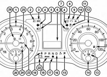
The multifunction lever controls the: • Turn Signals • Headlight Beams Low/High • Flash-To-Pass (Optical Horn) • Front and Rear Wipers — Washer Functions Turn Signals Move the multifunction lever up or down and the arrows on each side of the instrument cluster flash to show proper operation of the front and rear turn signal lights. NOTE: If either light remains on and does not flash, or there is a very fast flash rate, check for a defective outside light bulb. If an indicator fails to light when the lever is moved, the indicator bulb is defective.
it would suggest
that
Turn Signal Warning If the vehicle electronics sense that the vehicle has traveled at over 18 mph (29 km/h) for about 1 mile (1.6 km) with the turn signals on, a chime will sound to alert the driver. Lane Change Assist Tap the lever up or down once, without moving beyond the detent, and the turn signal (right or left) will flash three times then automatically turn off. High/Low Beam Switch When the headlights are turned on, pushing the multi- function lever toward the instrument panel will switch from low beams to high beams. Pulling back to the neutral position returns the headlights to the low beam operation.
UNDERSTANDING THE FEATURES OF YOUR VEHICLE 227
Flash-To-Pass You can signal another vehicle with your headlights by lightly pulling the multifunction lever toward you. This will cause the headlights to turn on at high beam and remain on until the lever is released. SmartBeam™ — If Equipped The SmartBeam™ system provides increased forward lighting at night by automating high beam control through the use of a digital camera mounted on the inside rearview mirror. This camera detects vehicle spe- cific light and automatically switches from high beams to low beams until the approaching vehicle is out of view. NOTE: Broken, muddy or obstructed headlights and taillights of vehicles in the field of view will cause headlights to remain on longer (closer to the vehicle). Also, dirt, film and other obstructions on the windshield or camera lens will cause the system to function improp- erly.
228 UNDERSTANDING THE FEATURES OF YOUR VEHICLE To Activate 1. Select “Automatic High Beams — ON” through the EVIC. Refer to “Electronic Vehicle Information Center (EVIC)/Customer-Programmable Features” in “Un- derstanding Your Instrument Panel” for further infor- mation.
2. Rotate the headlight switch counterclockwise to the
AUTO (A) position.
3. Push the multifunction lever away from you to switch the headlights to the high beam position. Refer to “Multifunction Lever” in this section for further infor- mation.
NOTE: This system will not activate until the vehicle is at, or above, 25 mph (40 km/h).
To Deactivate Perform either of the following steps to deactivate the SmartBeam™ system. 1. Select “Automatic High Beams — OFF” through the EVIC. Refer to “Electronic Vehicle Information Center (EVIC)/Customer-Programmable Features” in “Un- derstanding Your Instrument Panel” for further infor- mation.
2. Pull the multifunction lever toward you to switch the headlights from the high beam to the low beam position.
3. Rotate the headlight switch clockwise from the AUTO
(A) to the on position.
Battery Protection This feature provides battery protection to avoid wearing down the battery if the headlights, parking lights, or front fog lights are left on for extended periods of time when the ignition switch is in the LOCK position. After eight minutes of the ignition switch being in the LOCK position and the headlight switch in any position other than OFF or AUTO, the lights will turn off automatically until the next cycle of the ignition switch or headlight switch. The battery protection feature will be disabled if the ignition switch is turned to any other position other than LOCK during the eight minute delay.
WINDSHIELD WIPER AND WASHERS The wipers and washers are operated by a switch within the multifunction lever. Rotate the end of the multifunc- tion lever to select the desired wiper speed.
UNDERSTANDING THE FEATURES OF YOUR VEHICLE 229
Washer And Wiper Controls
NOTE: Always remove any buildup of snow that pre- vents the windshield wiper blades from returning to the off position. If the windshield wiper switch is turned off and the blades cannot return to the off position, damage to the wiper motor may occur.
230 UNDERSTANDING THE FEATURES OF YOUR VEHICLE
WARNING!
Sudden loss of visibility through the windshield could lead to a collision. You might not see other vehicles or other obstacles. To avoid sudden icing of the windshield during freezing weather, warm the windshield with the defroster before and during windshield washer use.
Intermittent Wiper System Use the intermittent wiper when weather conditions make a single wiping cycle with a variable pause be- tween cycles desirable. Rotate the end of the multifunc- tion lever to the first detent position, and then turn the end of the lever to select the desired delay interval. There are five delay settings, which allow you to regulate the wipe interval from a minimum of one cycle every second to a maximum of approximately 18 seconds between
cycles. The delay intervals will double in duration when the vehicle speed is 10 mph (16 km/h) or less. Windshield Wiper Operation Rotate the end of the lever upward, to the first detent past the intermittent settings for low-speed wiper operation. Rotate the end of the lever upward to the second detent past the intermittent settings for high-speed wiper opera- tion. Windshield Washers To use the Washer, push on the end of the lever to the second detent and hold while spray is desired. If the lever is pushed while on the intermittent setting, the wipers will turn on and operate for several wipe cycles after the lever is released, and then resume the intermittent inter- val previously selected. If the lever is pushed while the wipers are in the off position, the wipers will operate several wipe cycles, then turn off.
Mist Feature Press the end of the multifunction lever inward (toward the steering column) to the first detent and release for a single wiping cycle. NOTE: The mist feature does not activate the washer pump; therefore, no washer fluid will be sprayed on the windshield. The wash function must be used in order to spray the windshield with washer fluid. Rear Wiper And Washer Rotating the rotary ring to the first detent activates the rear intermittent wipers. To activate the washers, rotate the rotary ring fully forward and the washers will spray until the ring is released, and then resume the intermit- tent interval. NOTE: Rear window wipers function in the intermittent wiper speed only.
UNDERSTANDING THE FEATURES OF YOUR VEHICLE 231
Rain Sensing Wipers — If Equipped This feature senses moisture on the windshield and automatically activates the wipers for the driver. This feature is especially useful for road splash or overspray from the windshield washers of the vehicle ahead. Rotate the end of the multifunction lever to one of the five intermittent wiper sensitivity settings to activate this feature. The sensitivity of the system is adjustable from the multifunction lever. Wiper sensitivity position 3 has been calibrated for best overall wiping sensitivity. If the opera- tor desires more wiping sensitivity, they may select sensitivity positions 4 or 5. If the operator desires less wiping sensitivity, they may select sensitivity positions 2
or 1. Place the multifunction lever in the OFF position when not using the system.wiper speed is in the low or high position.
when ice or dried saltwater windshield.
232 UNDERSTANDING THE FEATURES OF YOUR VEHICLE NOTE: • The Rain Sensing feature will not operate when the • The Rain Sensing feature may not function properly is present on the • Use of Rain-X威 or products containing wax or silicone • The Rain Sensing feature can be turned on and off through the EVIC (if equipped). Refer to “Electronic Vehicle Information Center (EVIC)/Personal Settings (Customer-Programmable Features)” in “Understand- ing Your Instrument Panel” for further information.
may reduce rain sensor performance.
The Rain Sensing system has protective features for the wiper blades and arms. It will not operate under the following conditions: • Low Temperature Wipe Inhibit — The Rain Sensing feature will not operate when the ignition is first switched ON, and the vehicle is stationary, and the outside temperature is below 32°F (0°C), unless the wiper control on the multifunction lever is moved, or the vehicle speed becomes greater than 0 mph (0 km/h), or the outside temperature rises above freezing. • Neutral Wipe Inhibit — The Rain Sensing feature will not operate when the ignition is ON, and the transmis- sion shift lever is in the NEUTRAL position, and the vehicle speed is less than 5 mph (8 km/h), unless the wiper control on the multifunction lever is moved or the shift lever is moved out of the NEUTRAL position.
• Remote Start Mode Inhibit — On vehicles equipped with Remote Starting system, Rain Sensing wipers are not operational when the vehicle is in the remote start mode. Once the operator is in the vehicle and has placed the ignition switch in the RUN position, rain sensing wiper operation can resume, if it has been selected, and no other inhibit conditions (mentioned previously) exist.
TILT/TELESCOPING STEERING COLUMN This feature allows you to tilt the steering column upward or downward. It also allows you to lengthen or shorten the steering column. The tilt/telescoping lever is located below the steering wheel at the end of the steering column.
UNDERSTANDING THE FEATURES OF YOUR VEHICLE 233
Tilt/Telescoping Lever
To unlock the steering column, push the lever downward (toward the floor). To tilt the steering column, move the steering wheel upward or downward as desired. To lengthen or shorten the steering column, pull the steering wheel outward or push it inward as desired. To lock the
234 UNDERSTANDING THE FEATURES OF YOUR VEHICLE steering column in position, push the lever upward until fully engaged.
WARNING!
Do not adjust the steering column while driving. Adjusting the steering column while driving or driv- ing with the steering column unlocked, could cause the driver to lose control of the vehicle. Failure to follow this warning may result in serious injury or death.
HEATED STEERING WHEEL — IF EQUIPPED The steering wheel contains a heating element that helps warm your hands in cold weather. The heated steering wheel has only one temperature setting. Once the heated steering wheel has been turned on it will operate for approximately 58 to 70 minutes before automatically
shutting off. The heated steering wheel can shut off early or may not turn on when the steering wheel is already warm. The heated steering wheel switch is located on the switch bank below the climate controls.
Press the switch to turn on the heated steering wheel. The light on the switch will illuminate to indicate the steering wheel heater is on. Pressing the switch a second time will turn off the heated steering wheel and light indicator.
NOTE: The engine must be running for the heated steering wheel to operate. Vehicles Equipped With Remote Start On models that are equipped with remote start, the heated steering wheel can be programmed to come on during a remote start. Refer to “Remote Starting System
UNDERSTANDING THE FEATURES OF YOUR VEHICLE 235
ADJUSTABLE PEDALS — IF EQUIPPED The adjustable pedals system is designed to allow a greater range of driver comfort for steering wheel tilt and seat position. This feature allows the brake, accelerator, and clutch pedals (if equipped) to move toward or away from the driver to provide improved position with the steering wheel.
— If Equipped” in “Things to Know Before Starting Your Vehicle” for further information.
WARNING!
• Persons who are unable to feel pain to the skin because of advanced age, chronic illness, diabetes, spinal cord injury, medication, alcohol use, exhaus- tion, or other physical conditions must exercise care when using the steering wheel heater. It may cause burns even at low temperatures, especially if used for long periods. • Do not place anything on the steering wheel that insulates against heat, such as a blanket or steering wheel covers of any type and material. This may cause the steering wheel heater to overheat.
236 UNDERSTANDING THE FEATURES OF YOUR VEHICLE The switch is located on the left side of the steering column.
• The pedals can be adjusted with the ignition OFF. • The pedals cannot be adjusted when the vehicle is in REVERSE or when the Electronic Speed Control Sys- tem is on. The following messages will be displayed on vehicles equipped with the Electronic Vehicle Informa- tion System (EVIC) if the pedals are attempted to be adjusted when the system is locked out (“Adjustable Pedal Disabled — Cruise Control Engaged” or “Ad- justable Pedal Disabled — Vehicle In Reverse”.
NOTE: • Always adjust the pedals to a position that allows full • Further small adjustments may be necessary to find
pedal travel.
the best possible seat/pedal position.
Adjustable Pedal Switch
Press the switch forward to move the pedals forward (toward the front of the vehicle). Press the switch rearward to move the pedals rearward (toward the driver).
CAUTION!
Do not place any article under the adjustable pedals or impede its ability to move, as it may cause damage to the pedal controls. Pedal travel may become lim- ited if movement is stopped by an obstruction in the adjustable pedal’s path.
WARNING!
Do not adjust the pedals while the vehicle is moving. You could lose control and have an accident. Always adjust the pedals while the vehicle is parked.
ELECTRONIC SPEED CONTROL — IF EQUIPPED When engaged, the Electronic Speed Control takes over accelerator operations at speeds greater than 25 mph (40 km/h).
UNDERSTANDING THE FEATURES OF YOUR VEHICLE 237
The Electronic Speed Control buttons are located on the right side of the steering wheel.Electronic Speed Control Buttons
1 — ON/OFF 4 — CANCEL
2 — RES + 3 — SET -
238 UNDERSTANDING THE FEATURES OF YOUR VEHICLE NOTE: In order to ensure proper operation, the Elec- tronic Speed Control System has been designed to shut down if multiple Speed Control functions are operated at the same time. If this occurs, the Electronic Speed Control System can be reactivated by pushing the Electronic Speed Control ON/OFF button and resetting the desired vehicle set speed. To Activate Push the ON/OFF button. The Cruise Indicator Light in the instrument cluster will illuminate. To turn the system off, push the ON/OFF button a second time. The Cruise Indicator Light will turn off. The system should be turned off when not in use.
WARNING!
Leaving the Electronic Speed Control system on when not in use is dangerous. You could accidentally set the system or cause it to go faster than you want. You could lose control and have an accident. Always leave the system OFF when you are not using it.
To Set A Desired Speed Turn the Electronic Speed Control ON. When the vehicle has reached the desired speed, press the SET (-) button and release. Release the accelerator and the vehicle will operate at the selected speed. NOTE: The vehicle should be traveling at a steady speed and on level ground before pressing the SET button. To Deactivate A soft tap on the brake pedal, pushing the CANCEL button, or normal brake pressure while slowing the
vehicle will deactivate Electronic Speed Control without erasing the set speed memory. Pressing the ON/OFF button or turning the ignition switch OFF erases the set speed memory. To Resume Speed To resume a previously set speed, push the RES (+) button and release. Resume can be used at any speed above 20 mph (32 km/h). To Vary The Speed Setting When the Electronic Speed Control is set, you can in- crease speed by pushing the RES (+) button. If the button is continually pressed, the set speed will continue to increase until the button is released, then the new set speed will be established. Pressing the RES (+) button once will result in a 1 mph (1.6 km/h) increase in set speed. Each subsequent tap of the button results in an increase of 1 mph (1.6 km/h).
UNDERSTANDING THE FEATURES OF YOUR VEHICLE 239
To decrease speed while the Electronic Speed Control is set, push the SET (-) button. If the button is continually held in the SET (-) position, the set speed will continue to decrease until the button is released. Release the button when the desired speed is reached, and the new set speed will be established. Pressing the SET (-) button once will result in a 1 mph (1.6 km/h) decrease in set speed. Each subsequent tap of the button results in a decrease of 1 mph (1.6 km/h). To Accelerate For Passing Press the accelerator as you would normally. When the pedal is released, the vehicle will return to the set speed. Using Electronic Speed Control On Hills The transmission may downshift on hills to maintain the vehicle set speed.240 UNDERSTANDING THE FEATURES OF YOUR VEHICLE NOTE: The Electronic Speed Control system maintains speed up and down hills. A slight speed change on moderate hills is normal. On steep hills, a greater speed loss or gain may occur so it may be preferable to drive without Electronic Speed Control.
WARNING!
Electronic Speed Control can be dangerous where the system cannot maintain a constant speed. Your ve- hicle could go too fast for the conditions, and you could lose control and have an accident. Do not use Electronic Speed Control in heavy traffic or on roads that are winding, icy, snow-covered or slippery.
PARKSENSE姞 REAR PARK ASSIST — IF EQUIPPED The ParkSense威 Rear Park Assist system provides visual and audible indications of the distance between the rear fascia and a detected obstacle when backing up, e.g. during a parking maneuver. Refer to ParkSense威 System Usage Precautions for limitations of this system and recommendations. ParkSense威 will retain the last system state (enabled or disabled) from the last ignition cycle when the ignition is changed to the ON/RUN position. ParkSense威 can be active only when the shift lever is in REVERSE. If ParkSense威 is enabled at this shift lever position, the system will remain active until the vehicle speed is increased to approximately 11 mph (18 km/h) or above. The system will become active again if the vehicle speed is decreased to speeds less than approximately 10 mph (16 km/h).
ParkSense姞 Sensors The four ParkSense威 sensors, located in the rear fascia/ bumper, monitor the area behind the vehicle that is within the sensors’ field of view. The sensors can detect obstacles from approximately 12 in (30 cm) up to 79 in (200 cm) from the rear fascia/bumper in the horizontal direction, depending on the location, type and orienta- tion of the obstacle. ParkSense姞 Warning Display The ParkSense威 Warning screen will only be displayed if Sound and Display is selected from the Customer- Pro- grammable Features section of the Electronic Vehicle Information Center (EVIC). Refer to “Electronic Vehicle Information Center (EVIC)/Personal Settings (Customer- Programmable Features)” in “Understanding Your In- strument Panel” for further information.
UNDERSTANDING THE FEATURES OF YOUR VEHICLE 241
The ParkSense威 Warning Display is located in the Instru- ment cluster’s EVIC display. It provides both visual and audible warnings to indicate the distance between the rear fascia/bumper and the detected obstacle.ParkSense威 Warning Display
242 UNDERSTANDING THE FEATURES OF YOUR VEHICLE ParkSense姞 Display When the vehicle is in REVERSE, the warning display will turn ON indicating the system status.
Park Assist System ON
Park Assist System OFF
The system will indicate a detected obstacle by showing three solid arcs and will produce a one-half second tone. As the vehicle moves closer to the object the EVIC display will show fewer arcs and the sound tone will change from slow, to fast, to continuous.
UNDERSTANDING THE FEATURES OF YOUR VEHICLE 243
Slow Tone
Fast Tone
244 UNDERSTANDING THE FEATURES OF YOUR VEHICLE
The vehicle is close to the obstacle when the EVIC display shows one flashing arc and sounds a continuous tone. The following chart shows the warning alert operation when the system is detecting an obstacle:
Continuous Tone
UNDERSTANDING THE FEATURES OF YOUR VEHICLE 245
Rear Distance
(in/cm)
Greater than 79 in (200 cm)
Audible Alert
Chime Arcs
Radio Mute
None
None
No
WARNING ALERTS
79-39 in
(200-100 cm) Single 1/2
Second Tone3 Solid
(Continuous)
Yes
39-25 in
(100-65 cm)
Slow
3 Slow Flashing
Yes
25-12 in (65-30 cm)
Fast
2 Slow Flashing
Yes
Less than
12 in (30 cm) Continuous
1 Slow Flashing
Yes
NOTE: ParkSense威 will MUTE the radio, if on, when the system is sounding an audio tone. Enabling/Disabling ParkSense姞 ParkSense威 can be enabled and disabled through the Customer-Programmable Features section of the EVIC. The available choices are: OFF, Sound Only, or Sound and Display. Refer to “Electronic Vehicle Information Center
(EVIC)/Personal Settings (Customer-Programmable Fea- tures)” in “Understanding Your Instrument Panel” for further information. When ParkSense威 is disabled, the instrument cluster will display the “PARK ASSIST SYSTEM OFF” message for approximately five seconds. Refer to “Electronic Vehicle Information Center (EVIC)” in “Understanding Your Instrument Panel” for further information. When the shift lever is moved to REVERSE and the system is
246 UNDERSTANDING THE FEATURES OF YOUR VEHICLE disabled, the EVIC will display the “PARK ASSIST SYS- TEM OFF” message for as long as the vehicle is in REVERSE. Service The ParkSense姞 Rear Park Assist System When the ParkSense威 Rear Park Assist System is mal- functioning, the instrument cluster will actuate a single chime, once per ignition cycle, and it will display the “CLEAN PARK ASSIST SENSORS” or the “SERVICE PARK ASSIST SYSTEM” message. Refer to “Electronic Vehicle Information Center (EVIC)” in “Understanding Your Instrument Panel” for further information. When the shift lever is moved to REVERSE and the system has detected a faulted condition, the EVIC will display the “PARK ASSIST SYSTEM OFF” message for as long as the vehicle is in REVERSE. Under this condition, ParkSense will not operate. If “CLEAN PARK ASSIST SENSORS” appears in the Electronic Vehicle Information Center (EVIC) make sure
the outer surface and the underside of the rear fascia/ bumper is clean and clear of snow, ice, mud, dirt or other obstruction and then cycle the ignition. If the message continues to appear, see an authorized dealer. If “SERVICE PARK ASSIST SYSTEM” appears in the EVIC, see an authorized dealer. Cleaning The ParkSense姞 System Clean the ParkSense威 sensors with water, car wash soap and a soft cloth. Do not use rough or hard cloths. Do not scratch or poke the sensors. Otherwise, you could dam- age the sensors. ParkSense姞 System Usage Precautions
NOTE: • Ensure that the rear bumper is free of snow, ice, mud, dirt and debris to keep the ParkSense威 system operat- ing properly.
affect the performance of ParkSense威.
• Jackhammers, large trucks, and other vibrations could • When you turn ParkSense威 off, the instrument cluster will display “PARK ASSIST SYSTEM OFF.” Further- more, once you turn ParkSense威 off, it remains off until you turn it on again, even if you cycle the ignition key. • When you move the shift lever to the REVERSE position and ParkSense威 is turned off, the EVIC will display “PARK ASSIST SYSTEM OFF” message for as long as the vehicle is in REVERSE. • ParkSense威, when on, will MUTE the radio when it is • Clean the ParkSense威 sensors regularly, taking care not to scratch or damage them. The sensors must not be covered with ice, snow, slush, mud, dirt or debris. Failure to do so can result in the system not working
sounding a tone.
UNDERSTANDING THE FEATURES OF YOUR VEHICLE 247
properly. The ParkSense威 system might not detect an obstacle behind the fascia/bumper, or it could provide a false indication that an obstacle is behind the fascia/bumper. • Objects such as bicycle carriers, trailer hitches, etc., must not be placed within 12 in (30 cm) from the rear fascia/bumper while driving the vehicle. Failure to do so can result in the system misinterpreting a close object as a sensor problem, causing the “SERVICE PARK ASSIST SYSTEM” message to be displayed in the EVIC . • On vehicles equipped with a tailgate, ParkSense威 should be disabled when the tailgate is in the lowered or open position and the vehicle is in REVERSE. A lowered tailgate could provide a false indication that an obstacle is behind the vehicle.248 UNDERSTANDING THE FEATURES OF YOUR VEHICLE
CAUTION!
• ParkSense威 is only a parking aid and it is unable to recognize every obstacle, including small obstacles. Parking curbs might be temporarily detected or not detected at all. Obstacles located above or below the sensors will not be detected when they are in close proximity. • The vehicle must be driven slowly when using ParkSense威 in order to be able to stop in time when an obstacle is detected. It is recommended that the driver looks over his/her shoulder when using ParkSense威.
WARNING!
• Drivers must be careful when backing up even when using the Rear Park Assist system. Always check carefully behind your vehicle, look behind you, and be sure to check for pedestrians, animals, other vehicles, obstructions, and blind spots before backing up. You are responsible for safety and must continue to pay attention to your surround- ings. Failure to do so can result in serious injury or death.
(Continued)
WARNING! (Continued)
• Before using the Rear Park Assist system, it is strongly recommended that the ball mount and hitch ball assembly is disconnected from the ve- hicle when the vehicle is not used for towing. Failure to do so can result in injury or damage to vehicles or obstacles because the hitch ball will be much closer to the obstacle than the rear fascia when the loudspeaker sounds the continuous tone. Also, the sensors could detect the ball mount and hitch ball assembly, depending on its size and shape, giving a false indication that an obstacle is behind the vehicle.
UNDERSTANDING THE FEATURES OF YOUR VEHICLE 249
PARKVIEW姞 REAR BACK UP CAMERA — IF EQUIPPED Your vehicle may be equipped with the ParkView威 Rear Back Up Camera that allows you to see an on-screen image of the rear surroundings of your vehicle whenever the shift lever is put into REVERSE. The image will be displayed on the Navigation/Multimedia radio display screen along with a caution note to “check entire sur- roundings” across the top of the screen. After five sec- onds this note will disappear. The ParkView威 camera is located on the rear of the vehicle above the rear License plate. When the vehicle is shifted out of REVERSE, the rear camera mode is exited and the navigation or audio screen appears again.
250 UNDERSTANDING THE FEATURES OF YOUR VEHICLE When displayed, static grid lines will illustrate the width of the vehicle while a dashed center-line will indicate the center of the vehicle to assist with aligning to a hitch/ receiver. The static grid lines will show separate zones
that will help indicate the distance to the rear of the vehicle. The following table shows the approximate distances for each zone:
Zone Red Yellow Green
Distance to the rear of the vehicle
0 - 1 ft (0 - 30 cm)
1 ft - 3 ft (30 cm - 1 m)
3 ft or greater (1 m or greater)
WARNING!
Drivers must be careful when backing up even when using the ParkView威 Rear Back Up Camera. Always check carefully behind your vehicle, and be sure to check for pedestrians, animals, other vehicles, ob- structions, or blind spots before backing up. You are responsible for the safety of your surroundings and must continue to pay attention while backing up. Failure to do so can result in serious injury or death.
UNDERSTANDING THE FEATURES OF YOUR VEHICLE 251
CAUTION!
• To avoid vehicle damage, ParkView威 should only be used as a parking aid. The ParkView威 camera is unable to view every obstacle or object in your drive path. • To avoid vehicle damage, the vehicle must be driven slowly when using ParkView威 to be able to stop in time when an obstacle is seen. It is recom- mended that the driver look frequently over his/her shoulder when using ParkView威.
NOTE: If snow, ice, mud, or any foreign substance builds up on the camera lens, clean the lens, rinse with water, and dry with a soft cloth. Do not cover the lens.
252 UNDERSTANDING THE FEATURES OF YOUR VEHICLE Turning ParkView姞 On Or Off — With Navigation/Multimedia Radio
1. Press the “menu” hard-key. 2. Select “system setup” soft-key. 3. Press the “camera setup” soft-key. 4. Enable or disable the rear camera feature by selecting
the “enable rear camera in reverse” soft-key.
5. Press the “save” soft-key. Turning ParkView姞 On Or Off — Without Navigation/Multimedia Radio
1. Press the “menu” hard-key. 2. Select “system setup” soft-key. 3. Enable or disable the rear camera feature by selecting
“enable rear camera in reverse” soft-key.
OVERHEAD CONSOLES
Front Overhead Console Two versions of the overhead console are available. The base front overhead console model featured fixed incan- descent courtesy/reading lights, flip-down sunglass stor- age and conversation mirror. The premium front over- head console model features a LED focused light that illuminates the instrument panel cupholders, two swiv- eling LED lights, flip-down sunglass storage, conversa- tion mirror, optional power sliding door switches and an optional power liftgate switch. NOTE: Premium sunroof console models include all of above except sunglass storage.
UNDERSTANDING THE FEATURES OF YOUR VEHICLE 253
Courtesy/Interior Lighting At the forward end of the console are two courtesy lights (standard dome light has two buttons). The lights turn on when a front door, a sliding door or the liftgate is opened. If your vehicle is equipped with Remote Keyless Entry (RKE) the lights will also turn on when the UNLOCK button on the RKE transmitter is pressed. The courtesy lights also function as reading lights. Press in on each lens to turn these lights on while inside the vehicle. Press a second time to turn each light off. You may adjust the direction of these lights by pressing the outside ring, which is identified with four directional arrows (LED lamps only). The area around the instrument panel cupholders is also illuminated from a light in the overhead console (pre- mium console only). This light is turned on when the headlight switch is on, and will adjust in brightness when the dimmer control is rotated up or down.
Overhead Console
254 UNDERSTANDING THE FEATURES OF YOUR VEHICLE Sunglass Storage (Non-Sunroof Only) At the front of the overhead console, a compartment is provided for the storage of two pairs of sunglasses. From the closed position, press the door latch to open the compartment.
The door will slowly rotate to the full open position.
Full Open Position
From this position, the door can be fully closed or, by rotating upward about 3/4 of the way and releasing, positioned for conversation mirror use.
Over Door Latch
UNDERSTANDING THE FEATURES OF YOUR VEHICLE 255
Rear Courtesy/Reading Lights — If Equipped The overhead console has two sets of courtesy lights. The lights turn on when a front door, a sliding door or the liftgate is opened. If your vehicle is equipped with Remote Keyless Entry (RKE) the lights will also turn on when the UNLOCK button on the RKE transmitter is pressed.
Conversation Mirror Position
NOTE: From the “conversation mirror” position, the door can only be closed. To return to the full open position, the door must first be closed and then opened by pressing the latch again to release.
256 UNDERSTANDING THE FEATURES OF YOUR VEHICLE The courtesy lights also function as reading lights. Press in on each lens to turn these lights on while inside the vehicle. Press the lens a second time to turn each light off. You may adjust the direction of these lights by pressing the outside ring, which is identified with four directional arrows.
Rear Overhead Consoles — If Equipped The rear overhead storage system is available in two versions: with or without sunroof. An additional LED at the front of the rear console shines down on the front foot-well area while in courtesy mode, for added convenience.
Reading Lights
UNDERSTANDING THE FEATURES OF YOUR VEHICLE 257
Rear Console Halo Lighting The rear overhead console has recessed halo lighting around the perimeter of the console base. This feature provides additional lighting options while traveling and is controlled by the headlight switch. Refer to “Lights/ Halo Lights — If Equipped” in “Understanding the Features Of Your Vehicle” for further information.
GARAGE DOOR OPENER — IF EQUIPPED HomeLink威 replaces up to three hand-held transmitters that operate devices such as garage door openers, motor- ized gates, lighting or home security systems. The HomeLink威 unit is powered by your vehicles 12 Volt battery.
Overhead Compartment Features
1 — DVD* 2 — Rear HVAC 3 — Interior Lights 4 — Storage * If equipped, otherwise storage.
5 — Storage 6 — DVD* 7 — Interior Lights 8 — Halo Lighting
258 UNDERSTANDING THE FEATURES OF YOUR VEHICLE The HomeLink威 buttons, located on either the overhead console, headliner or sunvisor, designate the three differ- ent HomeLink威 channels. The HomeLink威 indicator is located above the center button.
HomeLink威 Buttons/Sunvisor/Headliner
NOTE: HomeLink威 is disabled when the Vehicle Secu- rity Alarm is active.
HomeLink威 Buttons/Overhead Consoles
UNDERSTANDING THE FEATURES OF YOUR VEHICLE 259
NOTE: • Erasing all channels should only be performed when programming HomeLink威 for the first time. Do not erase channels when programming additional buttons. • If you have any problems, or require assistance, please call toll-free 1–800–355–3515 or, on the Internet at www.HomeLink.com for information or assistance.
Before You Begin Programming HomeLink姞 Be sure that your vehicle is parked outside of the garage before you begin programming. For more efficient programming and accurate transmis- sion of the radio-frequency signal it is recommended that a new battery be placed in the hand-held transmitter of the device that is being programmed to the HomeLink威 system. Erase all channels before you begin programming. To erase the channels place the ignition in the ON/RUN position and press and hold the two outside HomeLink威 buttons (I and III) for up 20 seconds or until the red indicator flashes.
260 UNDERSTANDING THE FEATURES OF YOUR VEHICLE Programming A Rolling Code For programming garage door openers that were manu- factured after 1995. These garage door openers can be identified by the “LEARN” or “TRAIN” button located where the hanging antenna is attached to the garage door opener. It is NOT the button that is normally used to open and close the door. The name and color of the button may vary by manufacturer.
Training The Garage Door Opener
1 — Door Opener 2 — Training Button
1. Cycle the ignition to the ON/RUN position.
2. Place the hand-held transmitter 1 to 3 in (3 to 8 cm) away from the HomeLink威 button you wish to pro- gram while keeping the HomeLink威 indicator light in view.
3. Simultaneously press and hold both the HomeLink威 button you want to program and the hand-held trans- mitter button.
4. Continue to hold both buttons and observe the indi- cator light. The HomeLink威 indicator will flash slowly and then rapidly after HomeLink威 has received the frequency signal from the hand-held transmitter. Re- lease both buttons after the indicator light changes from slow to rapid.
5. At the garage door opener motor (in the garage), locate the “LEARN” or “TRAINING” button. This can usually be found where the hanging antenna wire is attached to the garage door opener/device motor.
UNDERSTANDING THE FEATURES OF YOUR VEHICLE 261
Firmly press and release the “LEARN” or “TRAIN- ING” button. On some garage door openers/devices there may be a light that blinks when the garage door opener/device is in the LEARN/TRAIN mode.NOTE: You have 30 seconds in which to initiate the next step after the LEARN button has been pressed. 6. Return to the vehicle and press the programmed HomeLink威 button twice (holding the button for two seconds each time). If the garage door opener/device activates, programming is complete.
NOTE: If the garage door opener/device does not acti- vate, press the button a third time (for two seconds) to complete the training. To program the remaining two HomeLink威 buttons, repeat each step for each remaining button. DO NOT erase the channels.
262 UNDERSTANDING THE FEATURES OF YOUR VEHICLE Reprogramming A Single HomeLink姞 Button To reprogram a channel that has been previously trained, follow these steps: 1. Turn the ignition switch to the ON/RUN position. 2. Press and hold the desired HomeLink威 button until the indicator light begins to flash after 20 seconds. Do not release the button.
3. Without releasing the button proceed with “Program- ming A Rolling Code” Step 2 and follow all remaining steps.
Programming A Non-Rolling Code For programming Garage Door Openers manufactured before 1995. 1. Turn the ignition switch to the ON/RUN position.
2. Place the hand-held transmitter 1 to 3 in (3 to 8 cm) away from the HomeLink威 button you wish to pro- gram while keeping the HomeLink威 indicator light in view.
3. Simultaneously press and hold both the Homelink威 button you want to program and the hand-held trans- mitter button.
4. Continue to hold both buttons and observe the indi- cator light. The Homelink威 indicator will flash slowly and then rapidly after HomeLink威 has received the frequency signal from the hand-held transmitter. Re- lease both buttons after the indicator light changes from slow to rapid.
5. Press and hold the programmed HomeLink威 button and observe the indicator light. • If the indicator light stays on constantly, program- ming is complete and the garage door/device should activate when the HomeLink威 button is pressed.
• To program the two remaining HomeLink威 buttons, repeat each step for each remaining button. DO NOT erase the channels.
Reprogramming A Single HomeLink姞 Button To reprogram a channel that has been previously trained, follow these steps: 1. Turn the ignition switch to the ON/RUN position. 2. Press and hold the desired HomeLink威 button until the indicator light begins to flash after 20 seconds. Do not release the button.
3. Without releasing the button proceed with “Program- ming A Rolling Code” Step 2 and follow all remaining steps.
UNDERSTANDING THE FEATURES OF YOUR VEHICLE 263
Canadian/Gate Operator Programming For programming transmitters in Canada/United States that require the transmitter signals to “time-out” after several seconds of transmission. Canadian radio frequency laws require transmitter sig- nals to time-out (or quit) after several seconds of trans- mission – which may not be long enough for HomeLink威 to pick up the signal during programming. Similar to this Canadian law, some U.S. gate operators are designed to time-out in the same manner. It may be helpful to unplug the device during the cycling process to prevent possible overheating of the garage door or gate motor. 1. Cycle the ignition to the ON/RUN position.
264 UNDERSTANDING THE FEATURES OF YOUR VEHICLE 2. Place the hand-held transmitter 1 to 3 in (3 to 8 cm) away from the HomeLink威 button you wish to pro- gram while keeping the HomeLink威 indicator light in view.
3. Continue to press and hold the HomeLink威 button, while you press and release (“cycle”), your hand-held transmitter every two seconds until HomeLink威 has successfully accepted the frequency signal. The indi- cator light will flash slowly and then rapidly when fully trained.
4. Watch for the HomeLink威 indicator to change flash rates. When it changes, it is programmed. It may take up to 30 seconds or longer in rare cases. The garage door may open and close while you are programming. 5. Press and hold the programmed HomeLink威 button
and observe the indicator light.
• If the indicator light stays on constantly, program- ming is complete and the garage door/device should activate when the HomeLink威 button is pressed. • To program the two remaining HomeLink威 buttons, repeat each step for each remaining button. DO NOT erase the channels.
If you unplugged the garage door opener/device for programming, plug it back in at this time. Reprogramming A Single HomeLink威 Button To reprogram a channel that has been previously trained, follow these steps: 1. Cycle the ignition to the ON/RUN position. 2. Press and hold the desired HomeLink威 button until the indicator light begins to flash after 20 seconds. Do not release the button.
3. Without
releasing
the button proceed with “Canadian/Gate Operator Programming” Step 2 and follow all remaining steps.
and release
Using HomeLink姞 To operate, press the programmed HomeLink威 button. Activation will now occur for the programmed device (i.e., garage door opener, gate opera- tor, security system, entry door lock, home/office light- ing, etc.,). The hand-held transmitter of the device may also be used at any time. Security It is advised to erase all channels before you sell or turn in your vehicle. To do this, press and hold the two outside buttons for 20
seconds until the red indicator flashes. Note that all channels will be erased. Individual channels cannot be erased.UNDERSTANDING THE FEATURES OF YOUR VEHICLE 265
The HomeLink威 Universal Transceiver is disabled when the Vehicle Security Alarm is active. Troubleshooting Tips If you are having trouble programming HomeLink威, here are some of the most common solutions: • Replace the battery in the original hand-held transmit- • Press the LEARN button on the Garage Door Opener • Did you unplug the device for programming andto complete the training for a Rolling Code.
ter.
remember to plug it back in?
If you have any problems, or require assistance, please call toll-free 1–800–355–3515 or, on the Internet at www.HomeLink.com for information or assistance.
266 UNDERSTANDING THE FEATURES OF YOUR VEHICLE
WARNING!
• Your motorized door or gate will open and close while you are programming the universal trans- ceiver. Do not program the transceiver if people, pets or other objects are in the path of the door or gate. Only use this transceiver with a garage door opener that has a “stop and reverse” feature as required by Federal safety standards. This includes most garage door opener models manufactured after 1982. Do not use a garage door opener without these safety features. Call toll-free 1–800–355–3515
or, on the Internet at www.HomeLink.com for safety information or assistance. • Vehicle exhaust contains carbon monoxide, a dan- gerous gas. Do not run your vehicle in the garage while programming the transceiver. Exhaust gas can cause serious injury or death.General Information This device complies with FCC rules Part 15 and Industry Canada RSS-210. Operation is subject to the following two conditions: 1. This device may not cause harmful interference. 2. This device must accept any interference that may be received including interference that may cause unde- sired operation.
NOTE: • The transmitter has been tested and it complies with FCC and IC rules. Changes or modifications not ex- pressly approved by the party responsible for compli- ance could void the user’s authority to operate the device. • The term IC before the certification/registration num- ber only signifies that Industry Canada technical speci- fications were met.
POWER SUNROOF — IF EQUIPPED The power sunroof switch is located between the sun visors on the overhead console.
Power Sunroof Switch
UNDERSTANDING THE FEATURES OF YOUR VEHICLE 267
WARNING!
• Never leave children in a vehicle with the key in the ignition switch (or with the ignition in the Accessory or Run position, for vehicles equipped with Keyless Enter-N-Go™). Occupants, particu- larly unattended children, can become entrapped by the power sunroof while operating the power sunroof switch. Such entrapment may result in serious injury or death. • In a collision, there is a greater risk of being thrown from a vehicle with an open sunroof. You could also be seriously injured or killed. Always fasten your seat belt properly and make sure all passen- gers are also properly secured. • Do not allow small children to operate the sunroof. Never allow your fingers, other body parts, or any object, to project through the sunroof opening. Injury may result.
268 UNDERSTANDING THE FEATURES OF YOUR VEHICLE Opening Sunroof — Express Press the switch rearward and release it within one-half second and the sunroof will open automatically from any position. The sunroof will open fully and stop automati- cally. This is called “Express Open”. During Express Open operation, any movement of the sunroof switch will stop the sunroof. Opening Sunroof — Manual Mode To open the sunroof, press and hold the switch rearward to full open. Any release of the switch will stop the movement and the sunroof will remain in a partially opened condition until the switch is pushed and held rearward again. Closing Sunroof — Express Press the switch forward and release it within one-half second and the sunroof will close automatically from any
position. The sunroof will close fully and stop automati- cally. This is called “Express Close”. During Express Close operation, any movement of the switch will stop the sunroof. Closing Sunroof — Manual Mode To close the sunroof, press and hold the switch in the forward position. Any release of the switch will stop the movement and the sunroof will remain in a partially closed condition until the switch is pushed and held forward again. Pinch Protect Feature This feature will detect an obstruction in the opening of the sunroof during Express Close operation. If an ob- struction in the path of the sunroof is detected, the sunroof will automatically retract. Remove the obstruc- tion if this occurs. Next, press the switch forward and release to Express Close.
NOTE: If three consecutive sunroof close attempts result in Pinch Protect reversals, the fourth close attempt will be a Manual Close movement with Pinch Protect disabled. Venting Sunroof — Express Press and release the Vent button within one half second and the sunroof will open to the vent position. This is called “Express Vent”, and it will occur regardless of sunroof position. During Express Vent operation, any movement of the switch will stop the sunroof. Sunshade Operation The sunshade can be opened manually. However, the sunshade will open automatically as the sunroof opens. NOTE: The sunshade cannot be closed if the sunroof is open.
UNDERSTANDING THE FEATURES OF YOUR VEHICLE 269
Wind Buffeting Wind buffeting can be described as the perception of pressure on the ears or a helicopter-type sound in the ears. Your vehicle may exhibit wind buffeting with the windows down, or the sunroof (if equipped) in certain open or partially open positions. This is a normal occur- rence and can be minimized. If the buffeting occurs with the rear windows open, open the front and rear windows together to minimize the buffeting. If the buffeting occurs with the sunroof open, adjust the sunroof opening to minimize the buffeting or open any window. Sunroof Maintenance Use only a non-abrasive cleaner and a soft cloth to clean the glass panel. Ignition Off Operation For Vehicles Not Equipped With The Electronic Vehicle Information Center (EVIC)
270 UNDERSTANDING THE FEATURES OF YOUR VEHICLE The power sunroof switch will remain active for 45
seconds after the ignition switch is turned to the LOCK position. Opening either front door will cancel this feature. For Vehicles Equipped With The EVIC The power sunroof switch will remain active for up to approximately ten minutes after the ignition switch is turned to the LOCK position. Opening either front door will cancel this feature. Sunroof Fully Closed Press the switch forward and release to ensure that the sunroof is fully closed.ELECTRICAL POWER OUTLETS — IF EQUIPPED Two 12 Volt (13 Amp) power outlets are located on the lower instrument panel, below the open storage bin. The driver-side power outlet is controlled by the ignition
switch and the passenger-side power outlet is connected directly to the battery. The driver-side power outlet will also operate a conventional cigar lighter unit (if equipped with an optional Smoker’s Package).
Instrument Panel Outlets
UNDERSTANDING THE FEATURES OF YOUR VEHICLE 271
One outlet in the removable floor console (if equipped) shares a fuse with the lower outlet in the instrument panel and is also connected to the battery. Do not exceed a maximum power of 160 Watts (13 Amps) shared between the lower panel outlet and the removable floor console outlet.NOTE: To ensure proper operation a MOPAR威 cigar knob and element must be used.
CAUTION!
• Do not exceed the maximum power of 160 Watts (13
Amps) at 12 Volts. If the 160 Watt (13 Amp) power rating is exceeded the fuse protecting the system will need to be replaced. • Power outlets are designed for accessory plugs only. Do not insert any other object in the power outlets as this will damage the outlet and blow the fuse. Improper use of the power outlet can cause damage not covered by your New Vehicle Limited Warranty.Removable Console Outlet
272 UNDERSTANDING THE FEATURES OF YOUR VEHICLE On vehicles equipped with the Super Console the power outlets are located under the retractable cover. To access the power outlets push down on the cover and slide it toward the instrument panel.
The outlet in the rear quarter panel near the liftgate and the upper outlet in the instrument panel are both con- trolled by the ignition switch. Each of these outlets can support 160 Watts (13 Amps). Do not exceed 160 Watts (13 Amps) for each of these outlets. The power outlets include tethered caps, labeled with a key or battery symbol indicating the power source. The power outlet, located on the lower instrument panel, is powered directly from the battery. Items plugged into this power outlet may discharge the battery and/or prevent the engine from starting.
Super Console Outlets
UNDERSTANDING THE FEATURES OF YOUR VEHICLE 273
WARNING!
To avoid serious injury or death: • Only devices designed for use in this type of outlet should be inserted into any 12 Volt outlet. • Do not touch with wet hands. • Close the lid when not in use and while driving the vehicle. • If this outlet is mishandled, it may cause an electric shock and failure.
Power Outlet Fuses
1 — M7 Fuse 20 A Yellow Power Outlet Center Seat (Opt) or with Console Rear 2 — M6 Fuse 20 A Yellow Cigar Lighter Instrument Panel or with Console Front 3 — M36 Fuse 20 A Yellow Power Outlet Instrument Panel or with Console Center
274 UNDERSTANDING THE FEATURES OF YOUR VEHICLE
CAUTION!
• Many accessories that can be plugged in draw power from the vehicle’s battery, even when not in use (i.e., cellular phones, etc.). Eventually, if plugged in long enough, the vehicle’s battery will discharge sufficiently to degrade battery life and/or prevent the engine from starting. • Accessories that draw higher power (i.e., coolers, vacuum cleaners, lights, etc.), will degrade the battery even more quickly. Only use these intermit- tently and with greater caution. • After the use of high power draw accessories, or long periods of the vehicle not being started (with accessories still plugged in), the vehicle must be driven a sufficient length of time to allow the alternator to recharge the vehicle’s battery.
(Continued)
CAUTION! (Continued)
• Power outlets are designed for accessory plugs only. Do not hang any type of accessory or acces- sory bracket from the plug. Improper use of the power outlet can cause damage.
POWER INVERTER — IF EQUIPPED A 110 Volt, 150 Watt inverter outlet (if equipped) converts DC current to AC current, and is located on the left rear trim panel immediately behind the second row left passenger seat.
UNDERSTANDING THE FEATURES OF YOUR VEHICLE 275
This outlet can power cellular phones, electronics and other low power devices requiring power up to 150
Watts. Certain high-end video games, such as Playsta- tion3 and XBox360 will exceed this power limit, as will most power tools. The power inverter is designed with built-in overload protection. If the power rating of 150 Watts is exceeded, the power inverter will automatically shut down. Once the electrical device has been removed from the outlet the inverter should automatically reset. If the power rating exceeds approximately 170 Watts, the power inverter may have to be reset manually. To reset the inverter manually press the power inverter button OFF and ON. To avoid overloading the circuit, check the power ratings on electrical devices prior to using the inverter.Power Inverter Outlet
The power inverter switch is located on the instrument panel below the climate controls. To turn on the power outlet, press the switch once. Press the switch a second time to turn the power outlet off.
276 UNDERSTANDING THE FEATURES OF YOUR VEHICLE CUPHOLDERS There are cupholders located throughout the interior. All liners are removable for cleaning. Pull the flexible liner from the cupholder drawer or tray starting at one edge for easy removal. Refer to “Cleaning The Instrument Panel Cupholders” in “Maintaining Your Vehicle” for further information. Instrument Panel Cupholders The instrument panel cupholders are located in a pull-out drawer just above the lower storage bin.
Front Cupholders
Pull the drawer out firmly until it stops, and place the container to be held in either one of the cupholder wells. The cupholders are designed to accommodate a wide variety of container types and sizes. Press down on the container to engage the cupholder retention features.
Super Console — If Equipped On models equipped with the Super Console, there are two cupholders located in the center of the console.
UNDERSTANDING THE FEATURES OF YOUR VEHICLE 277
For rear passengers two cupholders are located in the pull-out drawer, located in the back of the Super Console. Pull the drawer out to the first position to use the cupholders.Super Console Cupholders
Rear Cupholders
278 UNDERSTANDING THE FEATURES OF YOUR VEHICLE Premium Console Cupholders — If Equipped On models equipped with premium center consoles, there are four cupholders located on the top of the console.
Interior Bottle Holders There are four bottle holders located in the interior. One bottle holder is molded into each front interior door trim panels, and one bottle holder is molded into each side sliding interior door trim panel. Each holder accommo- dates up to a 20 oz (.6 L) plastic bottle.
WARNING!
If containers of hot liquid are placed in the bottle holder, they can spill when the door is closed, burn- ing the occupants. Be careful when closing the doors to avoid injury.
Premium Console Cupholders
UNDERSTANDING THE FEATURES OF YOUR VEHICLE 279
Smoker’s Package Kit — If Equipped With the optional authorized dealer-installed Smoker’s Package Kit, a removable ash receiver is inserted into one of the two cupholders in the center front instrument panel. To install the ash receiver, align the receiver so the thumb grip on the lid is facing rearward. Press the ash receiver into either of the cup wells to secure. Pull upward on the ash receiver to remove for cleaning and/or storage. The left rear trim panel cupholder is designed to accom- modate a second ash receiver, if desired.
STORAGE
Glove Compartments Upper and lower glove compartments are located on the passenger side of the instrument panel.
Interior Bottle Holder
Two outboard mesh pockets are on intermediate seating. The mesh pockets are flexible enough to hold juice boxes, toys, games or MP3 players, etc.
280 UNDERSTANDING THE FEATURES OF YOUR VEHICLE Upper Glove Compartment To open the upper compartment, press in on the button, located on the left side of the upper door. The door will automatically open.
Lower Glove Compartment To open the lower compartment pull out on the release handle.
Upper Compartment
To close the compartment door, push downward on the door’s surface to latch the door closed.
Lower Compartment
Door Trim Panel Storage
Front Door Storage Both interior front door panels have multiple pockets for storage.
WARNING!
If containers of hot liquid are placed in the bottle holder, they can spill when the door is closed, burn- ing the occupants. Be careful when closing the doors to avoid injury.
Driver Seatback Storage — If Equipped The driver’s seatback has a primary storage pocket on all models and an optional secondary mesh pocket.
UNDERSTANDING THE FEATURES OF YOUR VEHICLE 281
Driver’s Seatback Storage
1 — Bag Holder 2 — Standard Pocket 3 — Mesh Pocket
282 UNDERSTANDING THE FEATURES OF YOUR VEHICLE Umbrella Holder An umbrella holder has been conveniently molded into the left front door entry scuff molding.
Second Row Floor Storage Bins The area below the floor covers, located in front of the second row seats, is available for storage.
Umbrella Holder
Storage Bin Cover Lock Release