- 2013 Chrysler TOWN and Country Owners Manuals
- Chrysler TOWN and Country Owners Manuals
- 2006 Chrysler TOWN and Country Owners Manuals
- Chrysler TOWN and Country Owners Manuals
- 2011 Chrysler TOWN and Country Owners Manuals
- Chrysler TOWN and Country Owners Manuals
- 2007 Chrysler TOWN and Country Owners Manuals
- Chrysler TOWN and Country Owners Manuals
- 2010 Chrysler TOWN and Country Owners Manuals
- Chrysler TOWN and Country Owners Manuals
- 2005 Chrysler TOWN and Country Owners Manuals
- Chrysler TOWN and Country Owners Manuals
- 2009 Chrysler TOWN and Country Owners Manuals
- Chrysler TOWN and Country Owners Manuals
- 2004 Chrysler TOWN and Country Owners Manuals
- Chrysler TOWN and Country Owners Manuals
- 2012 Chrysler TOWN and Country Owners Manuals
- Chrysler TOWN and Country Owners Manuals
- 2008 Chrysler TOWN and Country Owners Manuals
- Chrysler TOWN and Country Owners Manuals
- Download PDF Manual
-
† Do not interconnect the hydraulic brake system or vacuum system of your vehicle with that of the trailer. This could cause inadequate braking and possible personal injury. † An electronically actuated trailer brake controller is required when towing a trailer with electronically actuated brakes. When towing a trailer equipped with a hydraulic surge actuated brake system, an electronic brake controller is not required. † Trailer brakes are recommended for trailers over 1,000
lbs (454 kg) and required for trailers in excess of 2,000
lbs (907 kg).404 STARTING AND OPERATING
CAUTION!
If the trailer weighs more than 1,000 lbs (454 kg) loaded, it should have its own brakes and they should be of adequate capacity. Failure to do this could lead to accelerated brake lining wear, higher brake pedal effort, and longer stopping distances.
WARNING!
Do not connect trailer brakes to your vehicle’s hy- draulic brake lines. It can overload your brake sys- tem and cause it to fail. You might not have brakes when you need them and could have an accident. Towing any trailer will increase your stopping dis- tance. When towing you should allow for additional space between your vehicle and the vehicle in front of you. Failure to do so could result in an accident.
Towing Requirements — Trailer Lights and Wiring Whenever you pull a trailer, regardless of the trailer size, stop lights and turn signals on the trailer are required for motoring safety. The Trailer Tow Package may include a four-pin or a seven-pin wiring harness. Use a factory approved trailer harness and connector. NOTE: Do not cut or splice wiring into the vehicles wiring harness. The electrical connections are all complete to the vehicle but you must mate the harness to a trailer connector. Refer to the following four-pin connector and seven-pin connector illustrations.
STARTING AND OPERATING 405
Four-Pin Connector
Seven-Pin Connector
Towing Tips Before setting out on a trip, practice turning, stopping and backing the trailer in an area away from heavy traffic.
406 STARTING AND OPERATING
Towing Tips — Automatic Transmission The DRIVE gear can be selected when towing. However, if frequent shifting occurs while in DRIVE, move the gear selector lever into third gear (with four-speed transmis- sion) or fifth gear (with six-speed transmission). NOTE: Moving the gear selector lever into third gear (with four-speed transmission) or fifth gear (with six- speed transmission) while operating the vehicle under heavy operating conditions will improve performance and extend transmission life by reducing excessive shift- ing and heat build up. This action will also provide better engine braking. The automatic transmission fluid and filter should be changed if you REGULARLY tow a trailer for more than 45 minutes of continuous operation. Refer to the “Main- tenance Schedule” in Section 8 of this manual for trans- mission fluid change intervals.
towing.
NOTE: † Check the automatic transmission fluid level before † The six-speed automatic transmission is sealed and requires an authorized dealer service center to check the transmission fluid.
Towing Tips — Electronic Speed Control (If Equipped) † Don’t use in hilly terrain or with heavy loads. † When using the speed control, if you experience speed drops greater than 10 mph (16 km/h), disengage until you can get back to cruising speed. † Use speed control in flat terrain and with light loads to
maximize fuel efficiency.
Towing Tips — Cooling System To reduce potential for engine and transmission over- heating, take the following actions: † City Driving When stopped for short periods of time, put transmission gear selector lever in NEUTRAL but do not increase engine idle speed. † Highway Driving Reduce speed. † Air Conditioning Turn off temporarily. † Refer to Cooling System Operating information in the Maintenance section of this manual for more informa- tion.
STARTING AND OPERATING 407
RECREATIONAL TOWING (BEHIND MOTORHOME, ETC.)
CAUTION!
Towing this vehicle behind another vehicle (flat- towing with all four wheels on the ground) IS NOT RECOMMENDED.
NOTE: wheels are off the ground.
If the vehicle requires towing make sure all four
WHAT TO DO IN EMERGENCIES
CONTENTS
m Hazard Warning Flasher . . . . . . . . . . . . . . . . . . 410
m If Your Engine Overheats . . . . . . . . . . . . . . . . . 410
m Jacking And Tire Changing . . . . . . . . . . . . . . . . 412
N Jack Location . . . . . . . . . . . . . . . . . . . . . . . . 412m Jump-Starting Procedure . . . . . . . . . . . . . . . . . . 424
m Freeing A Stuck Vehicle . . . . . . . . . . . . . . . . . . 426
m Towing A Disabled Vehicle . . . . . . . . . . . . . . . . 427N Towing With The Ignition Key . . . . . . . . . . . . 427 6
410 WHAT TO DO IN EMERGENCIES
HAZARD WARNING FLASHER
The hazard flasher switch is located in the center of the instrument panel below the radio.
To engage the Hazard Warning Flashers, depress the switch on the instrument panel. When the Hazard Warn- ing Switch is activated, all directional turn signals will flash on and off to warn oncoming traffic of an emer- gency. Push the switch a second time to turn off the flashers. This is an emergency warning system and should not be used when the vehicle is in motion. Use it when your vehicle is disabled and is creating a safety hazard for other motorists. When you must leave the vehicle to seek assistance, the Hazard Warning Flashers will continue to operate even though the ignition switch is OFF.
NOTE: With extended use, the Hazard Warning Flash- ers may wear down your battery.
IF YOUR ENGINE OVERHEATS In any of the following situations, you can reduce the potential for overheating by taking the appropriate ac- tion. † On the highways — Slow down. † In city traffic — While stopped, shift the transmission gear selector lever into NEUTRAL, but do not increase engine idle speed.
NOTE: There are steps that you can take to slow down an impending overheat condition. If your air conditioner is on, turn it off. The air conditioning system adds heat to the engine cooling system and turning off the A/C removes this heat. You can also turn the Temperature control to maximum heat, the Mode control to floor, and
the fan control to High. This allows the heater core to act as a supplement to the radiator and aids in removing heat from the engine cooling system.
CAUTION!
Driving with a hot cooling system could damage your vehicle. If temperature gauge reads “H”, pull over and stop the vehicle. Idle the vehicle with the air conditioner turned off until the pointer drops back into the normal range. If the pointer remains on the “H”, turn the engine off immediately, and call for service.
WHAT TO DO IN EMERGENCIES 411
WARNING!
A hot engine cooling system is dangerous. You or others could be badly burned by steam or boiling coolant. You may want to call a service center if your vehicle overheats. If you decide to look under the hood yourself, see Section 7, Maintenance, of this manual. Follow the warnings under the Cooling System Pressure Cap paragraph.
412 WHAT TO DO IN EMERGENCIES
JACKING AND TIRE CHANGING
WARNING!
† Getting under a jacked-up vehicle is dangerous. The vehicle could slip off the jack and fall on you. You could be crushed. Never get any part of your body under a vehicle that is on a jack. If you need to get under a raised vehicle, take it to a service center where it can be raised on a lift. † The jack is designed to use as a tool for changing tires only. The jack should not be used to lift the vehicle for service purposes. The vehicle should be jacked on a firm level surface only. Avoid ice or slippery areas.
WARNING!
For vehicles equipped with Stow ’n Go seating, if it is necessary to retrieve the spare tire from under the vehicle on the side of the vehicle close to moving traffic. Pull far enough off the road to avoid the danger of being hit.
Jack Location The jack, jack handle and winch handle tools are stowed behind the rear left side trim panel in the rear cargo area. Turn the two cover latches to release the cover.
WHAT TO DO IN EMERGENCIES 413
Spare Tire Removal For vehicles equipped with Stow ’n Go seating, the spare tire is stowed inside a protective cover located under the center of the vehicle by means of a cable winch mecha- nism. The “spare tire drive” nut is located on the floor, under a plastic cap at the front of the floor console. NOTE: The base console, if equipped, must be removed to raise and lower the spare tire. Refer to “Console Features” in Section 3, for the console removal procedure. The tool pouch contains three pieces and can be as- sembled into a Spare Tire Hook; to remove the compact spare tire/cover assembly from under the vehicle, or a Winch “T” Handle; to raise/lower the compact spare tire/cover assembly.
Rear Compartment Features
1 - Tie Down 2 - Switch Bank 3 - Tire Jack/Handle 4 - Cubby/Speaker Remove the pouch containing the scissors jack, handle, and tools.
5 - Liftgate Close Switch 6 - Bag Holders 7 - Child Seat LATCH Anchor 8 - Rechargeable Flash Light
jack
414 WHAT TO DO IN EMERGENCIES
Stow ’n Go Tools
Preparations For Jacking Park the vehicle on a firm level surface, avoid ice or slippery areas, set the parking brake and place the gear selector in PARK. Turn OFF the ignition. † Turn on the Hazard Warning Flasher.
† Block both the front and rear of the wheel diagonally oppo- site the jacking position. For example, if changing the right front tire, block the left rear wheel. † Passengers should not remain in the vehicle when the
vehicle is being jacked.
Jacking Instructions
Jack Warning Label
WHAT TO DO IN EMERGENCIES 415
WARNING!
Carefully follow these tire changing warnings to help prevent personal injury or damage to your vehicle: † Always park on a firm, level surface as far from the edge of the roadway as possible before raising the vehicle. † Block the wheel diagonally opposite the wheel to † Set the parking brake firmly and set an automatic transmission in park; a manual transmission in reverse.
be raised.
416 WHAT TO DO IN EMERGENCIES
WARNING!
jack.
jack.
Carefully follow these tire changing warnings to help prevent personal injury or damage to your vehicle: † Never start or run the engine with the vehicle on a † Do not let anyone sit in the vehicle when it is on a † Do not get under the vehicle when it is on a jack. † Only use the jack in the positions indicated and for † If working on or near a roadway, be extremely † To assure that spare tires, flat or inflated are securely stowed, spares must be stowed with the valve stem facing the ground.
lifting this vehicle during a tire change.
careful of motor traffic.
† Turn on the Hazard warning flasher.
1. Loosen (but do not remove) the wheel lug nuts by turning them to the left one turn while the wheel is still on the ground. 2. To remove the compact spare tire/cover assembly, assemble the winch handle extensions to form a “T’ and fit the winch “T” handle over the drive nut. Rotate the nut to the left until the winch mechanism stops turning freely. This will allow enough slack in the cable to allow you to pull the spare tire out from under the vehicle.
CAUTION!
The winch mechanism is designed for use with the winch “T” handle only. Use of an air wrench or other power tools is not recommended and can damage the winch.
3. Assemble the winch handle extensions to form the Spare Tire Hook and pull the compact spare tire/cover assembly from under the vehicle.
WARNING!
Getting under a jacked-up vehicle is dangerous. The vehicle could slip off the jack and fall on you. You could be crushed. Never get any part of your body under a vehicle that is on a jack. If you need to get under a raised vehicle, take it to a service center where it can be raised on a lift.
WHAT TO DO IN EMERGENCIES 417
If either front tire is flat, it may be necessary to NOTE: jack up the vehicle to remove the compact spare tire/ cover assembly from under the vehicle. Refer to jack engagement locations in the following steps for proper jack placement.
Spare Tire Hook & Removal
418 WHAT TO DO IN EMERGENCIES
4. When the compact spare tire/cover assembly is clear of the vehicle, stand the tire/cover assembly upright and remove the wheel spacer by squeezing the two retaining tabs together.
5. There are two jack engagement locations on each side of the vehicle body. These locations are on the sill flange of the vehicle body. NOTE: Rear jack location is between a pair of down- standing tabs on the sill flange of the vehicle body. Front jack location is on the sill flange of the vehicle body and aligns with the front door edge.
Squeezing Winch Retainer Tabs
WHAT TO DO IN EMERGENCIES 419
Jack Location
420 WHAT TO DO IN EMERGENCIES
CAUTION!
WARNING!
Do not attempt to raise the vehicle by jacking on locations other than those indicated in Step 5.
6. Place the wrench on the jack screw and turn to the right until the jack head is properly engaged in the described location. Do not raise the vehicle until you are sure the jack is securely engaged. 7. Raise the vehicle by turning the jack screw to the right, using the swivel wrench. Raise the vehicle only until the tire just clears the surface and enough clearance is obtained to install the spare tire. Minimum tire lift provides maximum stability.
Raising the vehicle higher than necessary can make the vehicle less stable. It could slip off the jack and hurt someone near it. Raise the vehicle only enough to remove the tire.
8. Remove the wheel lug nuts, for vehicles with wheel covers, remove the cover from the wheel by hand. Do not pry the wheel cover off. Then pull the wheel off the hub. 9. Install the compact spare tire. Lightly tighten the lug nuts. To avoid the risk of forcing the vehicle off the jack, do not tighten the lug nuts fully until the vehicle has been lowered. NOTE: Do not install the wheel cover on the compact spare. Do not use a hammer or force to install the wheel covers.
10. Lower the vehicle by turning the jack screw to the left. 11. Finish tightening the lug nuts. Push down on the wrench while tightening for increased leverage. Alternate lug nuts until each nut has been tightened twice. Correct wheel nut tightness is 95 ft lbs (130 N·m). If in doubt about the correct tightness, have them checked with a torque wrench by your authorized dealer or at a service station. 12. Lower the jack to its fully-closed position.
WARNING!
A loose tire or jack thrown forward in a collision or hard stop could endanger the occupants of the ve- hicle. Always stow the jack parts and the spare tire in the places provided. Have the deflated (flat) tire repaired or replaced immediately.
WHAT TO DO IN EMERGENCIES 421
13. Place the deflated (flat) tire and compact spare tire cover assembly in the rear cargo area. Do not stow the deflated tire in the spare tire location. Have the full sized tire repaired or replaced as soon as possible. 14. Stow the cable and wheel spacer before driving the vehicle. Reassemble the winch handle extensions to form a “T’ and fit the winch “T” handle over the drive nut. Rotate the nut to the right until the winch mechanism clicks at least three times. 15. Stow the jack, jack handle and winch handle tools. 16. Check the compact spare tire pressure as soon as possible. Correct pressure as required. Wheel Nuts All wheel nuts should be tightened occasionally to elimi- nate the possibility of wheel studs being sheared or the bolt holes in the wheels becoming elongated. This is especially important during the first few hundred miles
422 WHAT TO DO IN EMERGENCIES
just previously tightened until
of operation, and after each time a tire is changed, to allow the wheel nuts to become properly set. All nuts should first be firmly seated against the wheel. The nuts should then be tightened to recommended torque. Tighten the nuts to final torque in increments. Progress around the bolt circle, tightening the nut opposite to the nut torque is achieved. Recommended torque is 95 ft lbs (130 N·m). Secure The Spare Tire As Follows: 1. To stow the compact spare tire/cover assembly on vehicles equipped with Stow ’n Go seating, assemble the winch handle extensions to form a “T’ and fit the winch “T” handle over the drive nut. Rotate the nut to the left until the winch mechanism stops turning freely. This will allow enough slack in the cable to allow you to pull the wheel spacer out from under the vehicle.
final
WARNING!
A loose compact spare tire/cover assembly, thrown forward in a collision or hard stop could endanger the occupants of the vehicle. Always stow the com- pact spare tire with the cover assembly in the place provided.
CAUTION!
The winch mechanism is designed for use with the winch “T” handle only. Use of an air wrench or other power tools is not recommended and can damage the winch.
2. Assemble the winch handle extensions to form the Spare Tire Hook and pull the wheel spacer from under the vehicle. 3. Turn the compact spare tire so that the valve stem is down and place the tire into the spare tire cover assem- bly. Slide the wheel spacer through the center of the wheel and spare tire cover assembly so that the two retainer tabs snap out and engage the spare tire cover on the opposite side.
CAUTION!
The compact spare tire cover assembly must be used when the compact spare tire is stored. Failure to use this cover could drastically reduce the life of the compact spare tire.
WHAT TO DO IN EMERGENCIES 423
WARNING!
Verify that ’both’ retainer tabs of the wheel spacer have been properly extended through the center of the wheel and spare tire cover assembly. Failure to properly engage both retainer tabs could result in loss of the spare tire & cover assembly, which will cause vehicle damage and may cause loss of control of the vehicle.
4. Using the winch “T” handle, rotate the drive nut to the right until the compact spare tire/cover assembly is drawn into place against the underside of the vehicle. 5. Continue to rotate the nut to the right until you hear the winch mechanism click three times. It cannot be overtightened. Check under the vehicle to ensure the compact spare tire/cover assembly is positioned cor- rectly against the underside of the vehicle.
424 WHAT TO DO IN EMERGENCIES
CAUTION!
For vehicles equipped with Stow ’n Go seating, the Winch Mechanism is designed specifically to stow a COMPACT Spare Tire ONLY. Do not attempt to use the Winch to stow the Full Size ’Flat’ Tire, or any other Full Size Tire. Vehicle damage may result.
JUMP-STARTING PROCEDURE WARNING!
† DO NOT attempt to push or tow the vehicle to get it started. Vehicles
equipped with an automatic transmission cannot be started this way. Unburned fuel could enter the catalytic converter and once the engine has started, ignite and damage the converter and vehicle.
† If the vehicle has a discharged battery, booster cables may be used to † Battery fluid is a corrosive acid solution; DO NOT allow battery fluid to
obtain a start from another vehicle. This type of start can be dangerous if done improperly, so follow this procedure carefully.
contact eyes, skin or clothing. Don’t lean over battery when attaching clamps or allow the clamps to touch each other. If acid splashes in the eyes or on the skin, flush the contaminated area immediately with large quantities of water.
† A battery generates hydrogen gas which is flammable and explosive. Keep † During cold weather when temperatures are below freezing point, elec-
all flames or sparks away from the vent holes. DO NOT use a booster battery or any other booster source with an output that exceeds 12 volts.
trolyte in a discharged battery may freeze. DO NOT attempt jump-starting because the battery could rupture or explode. The battery temperature must be brought up above freezing point before attempting jump-start.
† Take special care to avoid the radiator cooling fan whenever the hood is
raised. The cooling fan is electrically operated and can start anytime the ignition switch is ON. You can be hurt by the fan.
When jump-starting, proceed as follows: 1. Wear eye protection and remove any metal jewelry such as watch bands or bracelets that might make an inadvertent electrical contact. 2. When a boost is provided by a battery in another vehicle, park that vehicle within booster cable reach and without letting the vehicles touch. Set the parking brake, place the automatic transmission selector lever into PARK and turn the ignition switch to the OFF position for both vehicles. 3. Turn OFF the heater, radio and all unnecessary elec- trical loads. 4. Connect one end of a jumper cable to the positive terminal of the discharged battery. Connect the other end of the same cable to the positive terminal of the booster battery.
WHAT TO DO IN EMERGENCIES 425
WARNING!
DO NOT permit vehicles to touch each other as this could establish a ground connection and personal injury could result.
5. Connect the other cable, first to the negative terminal of the booster battery, and then to the engine of the vehicle with the discharged battery. Make sure there is a good contact on the engine.
WARNING!
DO NOT connect the cable to the negative post of the discharge battery. The resulting electrical spark could cause the battery to explode.
426 WHAT TO DO IN EMERGENCIES
6. Start the engine in the vehicle which has the booster battery, let the engine idle a few minutes, then start the engine in the vehicle with the discharged battery. 7. When removing the jumper cables, reverse the above sequence exactly. Be careful of the moving belts and fan.
WARNING!
the battery vent;
Any procedure other than the jump-starting process listed could result in: † Personal injury caused by electrolyte squirting out † Personal injury or property damage due to battery † Damage to charging system of booster vehicle or
explosion;
of immobilized vehicle.
FREEING A STUCK VEHICLE If your vehicle becomes stuck in mud, sand or snow, it can often be moved by a rocking motion. Turn your steering wheel right and left to clear the area around the front wheels. Then shift the gear selector lever back and forth between REVERSE and DRIVE. Usually the least amount of accelerator pedal pressure to maintain the rocking motion without spinning the wheels is most effective.
WARNING!
Fast spinning tires can be dangerous. Forces generated by excessive wheel speeds may cause tire damage or failure. A tire could explode and injure someone. Do not spin your vehicle’s wheels faster than 35 mph (55
km/h) when you are stuck. And don’t let anyone near a spinning wheel, no matter what the speed.WHAT TO DO IN EMERGENCIES 427
CAUTION!
† Do not attempt to tow this vehicle from the front with sling type towing equipment. Damage to the front fascia will result. † Always use wheel lift equipment when towing from the front. The only other approved method of towing is with a flat bed truck. † Do not tow the vehicle from the rear. Damage to the rear sheet metal, liftgate and fascia will occur.
CAUTION!
Racing the engine or spinning the wheels too fast may lead to transmission overheating and failure. It can also damage the tires. Do not spin the wheels above 35 mph (55 km/h).
TOWING A DISABLED VEHICLE
Towing With The Ignition Key Your vehicle may be towed under the following condi- tions: The gear selector lever must be in NEUTRAL, the distance to be traveled must not exceed 100 mi (160 km), and the towing speed must not exceed 44 mph (72
km/h). Exceeding these towing limits may cause a trans- mission geartrain failure. If the transmission is not op- erative, or if the vehicle is to be towed more than 100 mi (160 km), the vehicle must be towed with the front wheels off the ground.428 WHAT TO DO IN EMERGENCIES
CAUTION!
† Do not push or tow this vehicle with another vehicle as damage to the bumper fascia and trans- mission may result. † If the vehicle being towed requires steering, the ignition switch must be in the OFF position, not in the LOCK or ACC positions.
If it is necessary to use the accessories while being towed (wipers, defrosters, etc.), the key must be in the ON position, not the ACC position. Make certain the trans- mission remains in NEUTRAL.
Towing Without The Ignition Key Special care must be taken when the vehicle is towed with the ignition in the LOCK position. The only ap- proved method of towing with out the ignition key is with a flat bed truck. Proper towing equipment is neces- sary to prevent damage to the vehicle. Towing This Vehicle Behind Another Vehicle (Flat towing with all four wheels on the ground) Flat towing of vehicles equipped with an automatic transmission, is only permitted within the limitations described in this section. Towing This Vehicle Behind Another Vehicle With A Tow Dolly The manufacturer does not recommend that you tow a front wheel drive vehicle on a tow dolly. Vehicle damage may occur.
MAINTAINING YOUR VEHICLE
CONTENTS
m 3.3L Engine Compartment . . . . . . . . . . . . . . . . 432
m 3.8L Engine Compartment . . . . . . . . . . . . . . . . 433
m 4.0L Engine Compartment . . . . . . . . . . . . . . . . 434
m Onboard Diagnostic System — OBD II . . . . . . . . 435
N Loose Fuel Filler Cap Message — Gascap . . . . 436m Emissions Inspection And Maintenance
Programs
. . . . . . . . . . . . . . . . . . . . . . . . . . . . 436
m Replacement Parts . . . . . . . . . . . . . . . . . . . . . . 438
m Authorized Dealer Service . . . . . . . . . . . . . . . . 438m Maintenance Procedures . . . . . . . . . . . . . . . . . . 439
N Engine Oil . . . . . . . . . . . . . . . . . . . . . . . . . . 439
N Engine Oil Filter . . . . . . . . . . . . . . . . . . . . . . 442
N Drive Belt . . . . . . . . . . . . . . . . . . . . . . . . . . . 443
N Spark Plugs . . . . . . . . . . . . . . . . . . . . . . . . . 443
N Engine Air Cleaner . . . . . . . . . . . . . . . . . . . . 443
N Catalytic Converter . . . . . . . . . . . . . . . . . . . . 444
N Maintenance-Free Battery . . . . . . . . . . . . . . . . 446
N Air Conditioner Maintenance . . . . . . . . . . . . . 448430 MAINTAINING YOUR VEHICLE
N Power Steering — Fluid Check . . . . . . . . . . . . 451
N Front Suspension — Ball Joints . . . . . . . . . . . . 451
N Steering Shaft Seal . . . . . . . . . . . . . . . . . . . . 451
N Drive Shaft Universal Joints . . . . . . . . . . . . . . 452
N Body Lubrication . . . . . . . . . . . . . . . . . . . . . 452
N Windshield Wiper Blades . . . . . . . . . . . . . . . . 452
N Cooling System . . . . . . . . . . . . . . . . . . . . . . . 454
N Hoses And Vacuum/Vapor Harnesses . . . . . . . 459
N Fuel System Connections . . . . . . . . . . . . . . . . 459
N Brakes . . . . . . . . . . . . . . . . . . . . . . . . . . . . . 460
N Automatic Transaxle . . . . . . . . . . . . . . . . . . . 462
N Front And Rear Wheel Bearings . . . . . . . . . . . 465N Appearance Care And Protection
From Corrosion . . . . . . . . . . . . . . . . . . . . . . 465
N Cleaning The Instrument Panel Cup Holders . . 471m Fuses/Totally Integrated Power Module
(TIPM)
. . . . . . . . . . . . . . . . . . . . . . . . . . . . . . 472
m Vehicle Storage . . . . . . . . . . . . . . . . . . . . . . . . 479
m Replacement Light Bulbs . . . . . . . . . . . . . . . . . 480
m Bulb Replacement . . . . . . . . . . . . . . . . . . . . . . 481N High Intensity Discharge Headlights (HID) —
If Equipped . . . . . . . . . . . . . . . . . . . . . . . . . 481
. . . . . . . . . . . . . . . . . . . . . 481N Quad Headlights N Front Park/Turn Signal And Side
Marker Lights . . . . . . . . . . . . . . . . . . . . . . . . 482
N Front Side Marker Lights . . . . . . . . . . . . . . . . 482N Fog Lights . . . . . . . . . . . . . . . . . . . . . . . . . . 483
N Rear Tail, Stop, Turn Signal, Side MarkerAnd Backup Lights . . . . . . . . . . . . . . . . . . . . 484
N Center High-Mounted Stop Light (CHMSL) . . . 485
N License Light . . . . . . . . . . . . . . . . . . . . . . . . 485MAINTAINING YOUR VEHICLE 431
m Fluids And Capacities . . . . . . . . . . . . . . . . . . . 486
m Fluids, Lubricants And Genuine Parts . . . . . . . . 487
N Engine . . . . . . . . . . . . . . . . . . . . . . . . . . . . . 487
N Chassis . . . . . . . . . . . . . . . . . . . . . . . . . . . . 488432 MAINTAINING YOUR VEHICLE
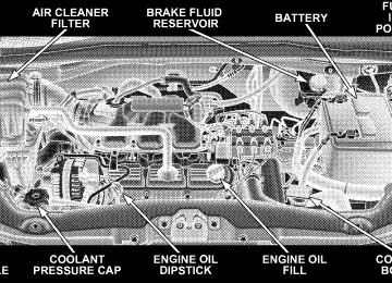
3.3L ENGINE COMPARTMENT
3.8L ENGINE COMPARTMENT
MAINTAINING YOUR VEHICLE 433
434 MAINTAINING YOUR VEHICLE
4.0L ENGINE COMPARTMENT
ONBOARD DIAGNOSTIC SYSTEM — OBD II Your vehicle is equipped with a sophisticated onboard diagnostic system called OBD II. This system monitors the performance of the emissions, engine, and automatic transmission control systems. When these systems are operating properly, your vehicle will provide excellent performance and fuel economy, as well as engine emis- sions well within current government regulations. If any of these systems require service, the OBD II system will turn on the “Malfunction Indicator Light.” It will also store diagnostic codes and other information to assist your service technician in making repairs. Al- though your vehicle will usually be drivable and not need towing, see your authorized dealer for service as soon as possible.
MAINTAINING YOUR VEHICLE 435
CAUTION!
† Prolonged driving with the “Malfunction Indica- tor Light” on could cause further damage to the emission control system. It could also affect fuel economy and driveability. The vehicle must be serviced before any emissions tests can be per- formed. † If the “Malfunction Indicator Light” is flashing while the engine is running, severe catalytic con- verter damage and power loss will soon occur. Immediate service is required.
436 MAINTAINING YOUR VEHICLE
Loose Fuel Filler Cap Message — gASCAP Should the “Loose Fuel Filler Cap” or “gASCAP” mes- sage appear, there may be a problem in the evaporative system. Before taking the vehicle into an authorized dealer, check first to see if the fuel filler cap is possibly loose, improperly installed, or damaged. A loose fuel filler cap message will be displayed in the instrument cluster. Tighten the gas cap until a 9clicking9 sound is heard. This is an indication that the gas cap is properly tightened. Press the odometer reset button to turn the message off. If the problem persists, the message will appear the next time the vehicle is started. If the problem is detected twice in a row, the system will turn on the Malfunction Indicator Light (MIL). Resolving the prob- lem will turn the MIL light off. Take your vehicle in to an authorized dealer.
EMISSIONS INSPECTION AND MAINTENANCE PROGRAMS In some localities, it may be a legal requirement to pass an inspection of this vehicle’s emissions control system. Failure to pass could prevent vehicle registration.
For states that require an Inspection and Mainte- nance (I/M), this check verifies the Malfunction Indicator Light (MIL) is functioning and is not on when the engine is running, and that the OBD II system is ready for testing. Normally, the OBD II system will be ready. The OBD II system may not be ready if the vehicle was recently serviced, recently had a dead battery, or a battery replace- ment. If the OBD II system should be determined not ready for the I/M test, the vehicle may fail the test.
This vehicle has a simple ignition key-actuated test, which you can use prior to going to the test station. To check if this vehicle’s OBD II system is ready, you must do the following: 1. Insert the ignition key into the ignition switch. 2. Turn the ignition to the ON position, but do not crank or start the engine. 3. If you crank or start the engine, you will have to start this test over. 4. As soon as you turn the ignition key to the ON position, you will see the MIL symbol come on as part of a normal bulb check. 5. Approximately 15 seconds later, one of two things will happen:
a. The MIL will flash for about 10 seconds and then return to being fully illuminated until you turn OFF
MAINTAINING YOUR VEHICLE 437
the ignition key or start the engine. This means that the vehicle’s OBD II system is not ready and you should not proceed to the I/M station. b. The MIL will not flash at all and will remain fully illuminated until you turn OFF the ignition key or start the engine. This means that the vehicle’s OBD II system is ready, and you can proceed to the I/M station.
If the OBD II system is not ready, you should see an authorized dealer or repair facility. If this vehicle was recently serviced or had a battery failure or replacement, you may need to do nothing more than drive the vehicle as you normally would in order for the OBD II system to update. A recheck with the above test routine may then indicate that the system is now ready. Regardless of whether the vehicle’s OBD II system is ready or not ready, if the MIL is illuminated during normal vehicle operation, you should have the vehicle
438 MAINTAINING YOUR VEHICLE
serviced before going to the I/M station. The I/M station can fail the vehicle because the MIL is on with the engine running.
NOTE: systems can result against you.
Intentional tampering with emissions control in civil penalties being assessed
REPLACEMENT PARTS Use of genuine Mopart parts for normal/scheduled maintenance and repairs is highly recommended to en- sure the designed performance. Damage or failures caused by the use of non-Mopart parts for maintenance and repairs will not be covered by the manufacturer’s warranty.
AUTHORIZED DEALER SERVICE Your authorized dealer has the qualified service person- nel, special tools, and equipment to perform all service operations in an expert manner. Service manuals are available which include detailed service information for your vehicle. Refer to these service manuals before attempting any procedure yourself.
WARNING!
You can be badly injured working on or around a motor vehicle. Only do service work for which you have the knowledge and the proper equipment. If you have any doubt about your ability to perform a service job, take your vehicle to a competent mechanic.
MAINTENANCE PROCEDURES The pages that follow contain the required maintenance services determined by the engineers who designed your vehicle. Besides the maintenance items for which there are fixed maintenance intervals, there are other items that should operate satisfactorily without periodic maintenance. However, if a malfunction of these items does occur, it could adversely affect the engine or vehicle performance. These items should be inspected if a malfunction is observed or suspected.
MAINTAINING YOUR VEHICLE 439
ENGINE OIL
Checking Oil Level To assure proper engine lubrication, the engine oil must be maintained at the correct level. Check the oil level at regular intervals, such as every fuel stop. The best time to check the engine oil level is about five minutes after a fully warmed engine is shut off or before starting the engine after it has sat overnight. Checking the oil while the vehicle is on level ground will improve the accuracy of the oil level readings. Maintain the oil level between the MIN and MAX markings on the dipstick. Adding one quart of oil when the reading is at the MIN mark will result in a MAX reading on these engines.
440 MAINTAINING YOUR VEHICLE
Engine Oil Dipstick
CAUTION!
Overfilling or underfilling will cause oil aeration or loss of oil pressure. This could damage your engine.
Change Engine Oil The oil change indicator system will remind you that it is time to take your vehicle in for scheduled maintenance. Refer to “Maintenance Schedule” in Section 8 of this manual for information on this system. NOTE: Under no circumstances should oil change intervals exceed 6,000 miles (10 000 km) or six months, whichever occurs first.
Engine Oil Selection For best performance and maximum protection under all types of operating conditions, the manufacturer only recommends engine oils that are API certified and meet the requirements of DaimlerChrysler Material Standard MS-6395.
American Petroleum Institute (API) Engine Oil Identification Symbol
This symbol means that the oil has been certified by the American Petroleum Institute (API). The manufacturer only recommends API Certified engine oils.
Engine Oil Viscosity (SAE Grade) — 3.3L & 3.8L Gasoline Engines SAE 5W-20 engine oil is recommended for all operating temperatures. This engine oil improves low temperature starting and vehicle fuel economy. Your engine oil filler cap also shows the recommended engine oil viscosity for your vehicle.
MAINTAINING YOUR VEHICLE 441
For information on engine oil filler cap location, refer to the Engine Compartment illustration in this section. Lubricants which do not have both, the engine oil certi- fication mark and the correct SAE viscosity grade num- ber should not be used. Engine Oil Viscosity (SAE Grade) — 4.0 Liter Engines SAE 10W-30 engine oil is preferred for all operating temperatures. The engine oil filler cap also shows the recommended engine oil viscosity for your vehicle. Lubricants which DO NOT have both, the engine oil certification mark and the correct SAE viscosity grade number should not be used.
442 MAINTAINING YOUR VEHICLE
Synthetic Engine Oils You may use synthetic engine oils provided the recom- mended oil quality requirements are met, and the recom- mended maintenance intervals for oil and filter changes are followed. Materials Added to Engine Oil The manufacture strongly recommends against the addi- tion of any additives (other than leak detection dyes) to the engine oil. Engine oil is an engineered product and its performance may be impaired by supplemental addi- tives. Disposing of Used Engine Oil And Oil Filters Care should be taken in disposing of used engine oil and oil filters from your vehicle. Used oil and oil filters, indiscriminately discarded, can present a problem to the environment. Contact your authorized dealer, service
station, or governmental agency for advice on how and where used oil and oil filters can be safely discarded in your area. ENGINE OIL FILTER The engine oil filter should be replaced at every engine oil change. Engine Oil Filter Selection The manufacturer’s engines have a full-flow type oil filter. Use a filter of this type for replacement. The quality of replacement filters varies considerably. Only high quality filters should be used to assure most efficient service. Mopart Engine Oil Filters are a high quality oil filter and are recommended.
DRIVE BELT At the mileage indicated in the maintenance schedule, replace the drive belt with a new drive belt. NOTE: The drive belt must be routed correctly to ensure proper drive function. SPARK PLUGS Spark plugs must fire properly to assure engine perfor- mance and emission control. New plugs should be in- stalled at the specified mileage. The entire set should be replaced if there is any malfunction due to a faulty spark plug. Malfunctioning spark plugs can damage the cata- lytic converter. For proper type of replacement spark plugs, refer to Fluids, Lubricants and Genuine Parts for correct spark plug type.
MAINTAINING YOUR VEHICLE 443
ENGINE AIR CLEANER Refer to the “Maintenance Schedule” in Section 8 of this manual for engine air cleaner filter maintenance inter- vals. NOTE: Be sure to follow the “dusty or off-road condi- tions” maintenance interval if applicable.
WARNING!
The air induction system (air cleaner, hoses, etc.) can provide a measure of protection in the case of engine backfire. Do not remove the air induction system (air cleaner, hoses, etc.) unless such removal is necessary for repair or maintenance. Make sure that no one is near the engine compartment before starting the vehicle with the air induction system (air cleaner, hoses, etc.) removed. Failure to do so can result in serious personal injury.
444 MAINTAINING YOUR VEHICLE
CATALYTIC CONVERTER The catalytic converter requires the use of unleaded fuel only. Leaded gasoline will destroy the effectiveness of the catalyst as an emission control device. Under normal operating conditions, the catalytic con- verter will not require maintenance. However, it is im- portant to keep the engine properly tuned to assure proper catalyst operation and prevent possible catalyst damage.
CAUTION!
Damage to the catalytic converter can result if your vehicle is not kept in proper operating condition. In the event of engine malfunction, particularly involv- ing engine misfire or other apparent loss of perfor- mance, have your vehicle serviced promptly. Contin- ued operation of your vehicle with a severe malfunction could cause the converter to overheat, resulting in possible damage to the converter and the vehicle.
NOTE: systems can result against you.
Intentional tampering with emissions control in civil penalties being assessed
WARNING!
A hot exhaust system can start a fire if you park over materials that can burn. Such materials might be grass or leaves coming into contact with your exhaust system. Do not park or operate your vehicle in areas where your exhaust system can contact anything that can burn.
In unusual situations involving grossly malfunctioning engine operation, a scorching odor may indicate severe and abnormal catalyst overheating. If this occurs, the vehicle should be stopped, the engine shut off and the vehicle allowed to cool. Thereafter, service, including a tune-up to manufacturer’s specifications, should be ob- tained immediately.
MAINTAINING YOUR VEHICLE 445
To minimize the possibility of catalyst damage: † Do not shut off the engine or interrupt the ignition when the transaxle is in gear and the vehicle is in motion. † Do not try to start engine by pushing or towing the † Do not idle the engine with any spark plug wires disconnected or removed, such as when diagnostic testing, or for prolonged periods during very rough idling or malfunctioning operating conditions.
vehicle.
446 MAINTAINING YOUR VEHICLE
Exhaust System The best protection against carbon monoxide entry into the vehicle body is a properly maintained engine exhaust system. Whenever a change is noticed in the sound of the exhaust system, when exhaust fumes can be detected inside the vehicle, or when the underside or rear of the vehicle is damaged, have a competent mechanic inspect the com- plete exhaust system and adjacent body areas for broken, damaged, deteriorated, or mispositioned parts. Open seams or loose connections could permit exhaust fumes to seep into the passenger compartment. In addition, inspect the exhaust system each time the vehicle is raised for lubrication or oil change. Replace as required.
WARNING!
Exhaust gases can injure or kill. They contain carbon monoxide (CO) which is colorless and odorless. Breathing it can make you unconscious and can eventually poison you. To avoid breathing CO, refer to “Exhaust Gas” in the Safety Tips section of this manual.
MAINTENANCE-FREE BATTERY The top of the MAINTENANCE-FREE battery is perma- nently sealed. You will never have to add water, nor is periodic maintenance required.
WARNING!
† Battery fluid is a corrosive acid solution and can burn or even blind you. Don’t allow battery fluid to contact your eyes, skin or clothing. Don’t lean over a battery when attaching clamps. If acid splashes in eyes or on skin, flush the area imme- diately with large amounts of water. † Battery gas is flammable and explosive. Keep flame or sparks away from the battery. Don’t use a booster battery or any other booster source with an output greater than 12 volts. Don’t allow cable clamps to touch each other. † Battery posts, terminals and related accessories contain lead and lead compounds. Wash hands after handling.
MAINTAINING YOUR VEHICLE 447
CAUTION!
† It is essential when replacing the cables on the battery that the positive cable is attached to the positive post and the negative cable is attached to the negative post. Battery posts are marked posi- tive (+) and negative (-) and identified on the battery case. Cable clamps should be tight on the terminal posts and free of corrosion. † If a “fast charger” is used while the battery is in the vehicle, disconnect both vehicle battery cables before connecting the charger to battery. Do not use a “fast charger” to provide starting voltage.
448 MAINTAINING YOUR VEHICLE
AIR CONDITIONER MAINTENANCE For best possible performance, your air conditioner should be checked and serviced by an authorized dealer at the start of each warm season. This service should include cleaning of the condenser fins and a system performance check. Drive belt tension should also be checked at this time.
WARNING!
† Use only refrigerants and compressor lubricants approved by the manufacturer for your air condi- tioning system. Some unapproved refrigerants are flammable and can explode, injuring you. Other unapproved refrigerants or lubricants can cause the system to fail, requiring costly repairs. Refer to Section 3 of the Warranty Information book for further warranty information. † The air conditioning system contains refrigerant under high pressure. To avoid risk of personal injury or damage to the system, adding refrigerant or any repair requiring lines to be disconnected should be done by an experienced repairman.
Refrigerant Recovery And Recycling R-134a Air Conditioning Refrigerant is a hydrofluoro- carbon (HFC) that is endorsed by the Environmental Protection Agency and is an ozone-saving product. How- ever, the manufacturer recommends that air conditioning service be performed by an authorized dealer or other an authorized service facility using recovery and recycling equipment. NOTE: Use only manufacturer approved A/C System Sealers, Stop Leak Products, Seal Conditioners, Compres- sor Oil, or Refrigerants. A/C Air Filter — If Equipped Refer to the “Maintenance Schedule” in Section 8 of this manual for A/C Air Filter service intervals.
MAINTAINING YOUR VEHICLE 449
WARNING!
Do not remove the A/C Air Filter while the blower is operating or personal injury may result.
The A/C Air Filter is located in the fresh air inlet behind the glove box. Perform the following procedure to re- place the filter: 1. Open the glove box and remove all contents. 2. Push in on the sides of the glove box and lower the door. 3. Pivot the glove box downward.
450 MAINTAINING YOUR VEHICLE
4. Disengage the two retaining tabs that secure the filter cover to the HVAC housing and remove the cover.
A/C Air Filter Replacement
5. Remove the A/C Air Filter by pulling it straight out of the housing.
6. Install the A/C Air Filter with the arrow on the filter pointing toward the floor. When installing the filter cover, make sure the retaining tabs fully engage the cover.
CAUTION!
The A/C Air Filter is labeled with an arrow to indicate airflow direction through the filter. Failure to properly install the filter will result in the need to replace it more often.
7. Rotate the glove box door back into position.
POWER STEERING — FLUID CHECK Checking the power steering fluid level at a defined service interval is not required. The fluid should only be checked if a leak is suspected, abnormal noises are apparent, and/or the system is not functioning as antici- pated. Coordinate inspection efforts through an autho- rized DaimlerChrysler Dealership.9
WARNING!
Fluid level should be checked on a level surface and with the engine off to prevent injury from moving parts and to ensure accurate fluid level reading. Do not overfill. Use only manufacturer’s recommended power steering fluid.
MAINTAINING YOUR VEHICLE 451
If necessary, add fluid to restore to the proper indicated level. With a clean cloth, wipe any spilled fluid from all surfaces. Refer to Fluids, Lubricants, and Genuine Parts for correct fluid type. FRONT SUSPENSION — BALL JOINTS The front suspension ball joints are permanently sealed. No regular maintenance is required for these compo- nents. STEERING SHAFT SEAL The steering shaft seal, at the point where the shaft passes through the bulkhead, is lubricated when it is installed. If the seal becomes noisy when the steering shaft is turned, it should be lubricated with a multipurpose grease. Mopart multipurpose lubricant is recommended. Steering Linkage The tie rod end ball joints are permanently lubricated and do not require periodic maintenance.
452 MAINTAINING YOUR VEHICLE
DRIVE SHAFT UNIVERSAL JOINTS Your vehicle has constant velocity universal joints. Peri- odic lubrication of these joints is not required. However, the joint boots should be inspected for external leakage or damage when other maintenance is performed. If leakage or damage is evident, the universal joint boot and grease should be replaced immediately. Continued operation could result in failure of the univer- sal joint due to water and dirt contamination of the grease. This would require complete replacement of the joint assembly. BODY LUBRICATION Locks and all body pivot points, including such items as seat tracks, doors, liftgate, sliding doors and hood hinges, should be lubricated periodically to assure quiet, easy operation and to protect against rust and wear. Prior to the application of any lubricant, the parts concerned should be wiped clean to remove dust and grit; after
lubricating excess oil and grease should be removed. Particular attention should also be given to hood latching components to ensure proper function. When performing other underhood services, the hood latch, release mecha- nism and safety catch should be cleaned and lubricated. The external lock cylinders should be lubricated twice a year, preferably in the Fall and Spring. Apply a small amount of a high quality lubricant such as Mopart Lock Cylinder Lubricant directly into the lock cylinder. WINDSHIELD WIPER BLADES The rubber edges of the wiper blades and the windshield should be cleaned periodically with a sponge or soft cloth and a mild nonabrasive cleaner. This will remove accu- mulations of salt or road film. Operation of the wipers on dry glass for long periods may cause deterioration of the wiper blades. Always use washer fluid when using the wipers to remove salt or dirt from a dry windshield.
Avoid using the wiper blades to remove frost or ice from the windshield. Keep the blade rubber out of contact with petroleum products such as engine oil, gasoline, etc. Windshield and Rear Window Washers The fluid reservoir for the windshield washers and the rear window washer is shared. It is located in the engine compartment and should be checked for fluid level at regular intervals. Fill the reservoir with windshield washer solvent (not radiator antifreeze) and operate the system for a few seconds to flush out the residual water. The washer fluid reservoir will hold a full gallon of fluid when the Low Washer Fluid Light illuminates.
MAINTAINING YOUR VEHICLE 453
WARNING!
Commercially available windshield washer solvents are flammable. They could ignite and burn you. Care must be exercised when filling or working around the washer solution.
After the engine has warmed, operate the defroster for a few minutes to reduce the possibility of smearing or freezing the fluid on the cold windshield. Mopart All Weather Windshield Washer Solution, used with water as directed on the container, aids cleaning action, reduces the freezing point to avoid line clogging, and is not harmful to paint or trim.
454 MAINTAINING YOUR VEHICLE
COOLING SYSTEM
WARNING!
† When working near the radiator cooling fan, dis- connect the fan motor lead or turn the ignition switch to the OFF position. The fan is temperature controlled and can start at anytime the ignition switch is in the ON position. † You or others can be badly burned by hot coolant or steam from your radiator. If you see or hear steam coming from under the hood, don’t open the hood until the radiator has had time to cool. Never try to open a cooling system pressure cap when the radiator is hot.
Coolant Checks Check the engine coolant (antifreeze) protection every 12
months (before the onset of freezing weather, where applicable). If coolant is dirty or rusty in appearance, the system should be drained, flushed and refilled with fresh coolant. Check the front of the A/C condenser for any accumulation of bugs, leaves, etc. If dirty, clean by gently spraying water from a garden hose vertically down the face of the condenser. Check the coolant recovery bottle tubing for brittle rub- ber, cracking, tears, cuts and tightness of the connection at the bottle and radiator. Inspect the entire system for leaks. With the engine at normal operating temperature (but not running), check the cooling system pressure cap for proper vacuum sealing by draining a small amount of coolant from the radiator drain cock. If the cap is sealing properly, the engine coolant (antifreeze) will begin todrain from the coolant recovery bottle. DO NOT RE- MOVE THE COOLANT PRESSURE CAP WHEN THE COOLING SYSTEM IS HOT. Cooling System — Drain, Flush and Refill The system should be drained, flushed, and refilled at the intervals shown in the “Maintenance Schedule” in Sec- tion 8 of this manual. If the solution is dirty or contains a considerable amount of sediment, clean and flush with a reliable cooling system cleaner. Follow with a thorough rinsing to remove all deposits and chemicals. Properly dispose of old antifreeze solution. Selection Of Coolant Use only the manufacturer’s recommended coolant, refer to Fluids, Lubricants and Genuine Parts for correct coolant type.
MAINTAINING YOUR VEHICLE 455
CAUTION!
Mixing of coolants other than specified Hybrid Or- ganic Additive Technology (HOAT) engine coolants, may result in engine damage and may decrease corrosion protection. If a non-HOAT coolant is intro- duced into the cooling system in an emergency, it should be replaced with the specified coolant as soon as possible. Do not use plain water alone or alcohol base engine coolant (antifreeze) products. Do not use additional rust inhibitors or anti-rust products, as they may not be compatible with the radiator engine coolant and may plug the radiator. This vehicle has not been designed for use with Propylene Glycol based coolants. Use of Propylene Glycol based coolants is not recommended.
456 MAINTAINING YOUR VEHICLE
Adding Coolant Your vehicle has been built with an improved engine coolant that allows extended maintenance intervals. This coolant can be used up to five years or 102,000 mi (170
000 km) before replacement. To prevent reducing this extended maintenance period, it is important that you use the same coolant throughout the life of your vehicle. Please review these recommendations for using Hybrid Organic Additive Technology (HOAT) coolant. When adding coolant, a minimum solution of 50% rec- ommended Mopart Antifreeze/ Coolant Five Year/ 100,000 mi (160 934 km) Formula HOAT (Hybrid Organic Additive Technology), or equivalent, in water should be used. Use higher concentrations (not to exceed 70%) if temperatures below 234°F (237°C ) are anticipated. Use only high purity water such as distilled or deionized water when mixing the water/engine coolant solution.The use of lower quality water will reduce the amount of corrosion protection in the engine cooling system. Please note that it is the owner’s responsibility to main- tain the proper level of protection against freezing ac- cording to the temperatures occurring in the area where the vehicle is operated. NOTE: Mixing coolant types will decrease the life of the engine coolant and will require more frequent coolant changes. Cooling System Pressure Cap The cap must be fully tightened to prevent loss of coolant, and to ensure that coolant will return to the radiator from the coolant recovery bottle. The cap should be inspected and cleaned if there is any accumulation of foreign material on the sealing surfaces.
WARNING!
† The warning words “DO NOT OPEN HOT” on the cooling system pressure cap are a safety pre- caution. Never add coolant when the engine is overheated. Do not loosen or remove the cap to cool an overheated engine. Heat causes pressure to build up in the cooling system. To prevent scald- ing or injury, do not remove the pressure cap while the system is hot or under pressure. † Do not use a pressure cap other than the one specified for your vehicle. Personal injury or en- gine damage may result.
Disposal of Used Coolant Used ethylene glycol-based engine coolant is a regulated substance requiring proper disposal. Check with your local authorities to determine the disposal rules for your
MAINTAINING YOUR VEHICLE 457
community. To prevent ingestion by animals or children do not store ethylene glycol-based engine coolant in open containers or allow it to remain in puddles on the ground. If ingested by a child, contact a physician immediately. Clean up any ground spills immediately. Coolant Level The coolant bottle provides a quick visual method for determining that the coolant level is adequate. With the engine cold, the level of the coolant in the coolant recovery bottle should be between the ranges indicated on the bottle. The radiator normally remains completely full, so there is no need to remove the radiator cap unless checking for coolant freeze point or replacing coolant. Advise your service attendant of this. As long as the engine operating temperature is satisfactory, the coolant bottle need only be checked once a month.
458 MAINTAINING YOUR VEHICLE
When additional coolant is needed to maintain the proper level, it should be added to the coolant bottle. Do not overfill. Points To Remember NOTE: When the vehicle is stopped after a few miles (a few kilometers) of operation, you may observe vapor coming from the front of the engine compartment. This is normally a result of moisture from rain, snow, or high humidity accumulating on the radiator and being vapor- ized when the thermostat opens, allowing hot coolant to enter the radiator. If an examination of your engine compartment shows no evidence of radiator or hose leaks, the vehicle may be safely driven. The vapor will soon dissipate. † Do not overfill the coolant recovery bottle.
† Check coolant freeze point in the radiator and in the coolant recovery bottle. If antifreeze needs to be added, contents of coolant recovery bottle must also be protected against freezing. † If frequent coolant additions are required, or if the level in the coolant recovery bottle does not drop when the engine cools, the cooling system should be pres- sure tested for leaks. † Maintain coolant concentration at 50% HOAT engine coolant (minimum) and distilled water for proper corrosion protection of your engine which contains aluminum components. † Make sure that the radiator and coolant recovery bottle overflow hoses are not kinked or obstructed. † Keep the front of the radiator clean. If your vehicle is equipped with air conditioning, keep the front of the condenser clean, also.
† Do not change the thermostat for summer or winter operation. If replacement is ever necessary, install ONLY the correct type thermostat. Other designs may result in unsatisfactory coolant performance, poor gas mileage, and increased emissions.
HOSES AND VACUUM/VAPOR HARNESSES Inspect surfaces of hoses and nylon tubing for evidence of heat and mechanical damage. Hard or soft spots, brittle rubber, cracking, tears, cuts, abrasions, and exces- sive swelling indicate deterioration of the rubber. Pay particular attention to those hoses nearest to high heat sources such as the exhaust manifold. Inspect hose routing to be sure hoses do not come in contact with any heat source or moving component which may cause heat damage or mechanical wear. Ensure nylon tubing in these areas has not melted or collapsed.
MAINTAINING YOUR VEHICLE 459
Inspect all hose connections such as clamps and cou- plings to make sure they are secure and no leaks are present. Components should be replaced immediately if there is any evidence of wear or damage that could cause failure. FUEL SYSTEM CONNECTIONS The Electronic Fuel Injection high-pressure fuel system’s hoses and quick connect fittings have unique material characteristics that provide adequate sealing and resist attack by deteriorated gasoline. You are urged to use only the manufacture specified hoses with quick connect fittings, or their equivalent in material and specification, in any fuel system servicing. It is mandatory to replace any damaged hoses or quick connect fittings that have been removed during service. Care should be taken in installing quick connect fittings to ensure they are properly installed and fully connected. See your authorized dealer for service.
460 MAINTAINING YOUR VEHICLE
BRAKES In order to assure brake system performance, all brake system components should be inspected periodically. Suggested service intervals can be found in the Mainte- nance Schedules.
WARNING!
Riding the brakes can lead to brake failure and possibly an accident. Driving with your foot resting or riding on the brake pedal can result in abnormally high brake temperatures, excessive lining wear, and possible brake damage. You wouldn’t have your full braking capacity in an emergency.
Brake And Power Steering Hoses When the vehicle is serviced for scheduled maintenance, inspect surface of hoses and nylon tubing for evidence of heat and mechanical damage. Hard and brittle rubber,
cracking, tears, cuts, abrasion, and excessive swelling indicate deterioration of the rubber. Particular attention should be made to examining those hose surfaces nearest to high heat sources, such as the exhaust manifold. Ensure nylon tubing in these areas has not melted or collapsed. Inspect all hose connections such as clamps and cou- plings to make sure they are secure and no leaks are present. NOTE: Often, fluid such as oil, power steering fluid, and brake fluid are used during assembly plant opera- tions to facilitate the assembly of hoses to couplings. Therefore, oil wetness at the hose-coupling area is not necessarily an indication of leakage. Actual dripping of hot fluid when systems are under pressure (during vehicle operation), should be noted before hose is re- placed based on leakage.
Inspection of brake hoses should be performed NOTE: whenever the brake system is serviced and every engine oil change. Inspect hydraulic brake hoses for surface cracking, scuffing, or worn spots. If there is any evidence of cracking, scuffing, or worn spots, the hose should be replaced immediately! Eventual deterioration of the hose can take place resulting in a possibility of a burst failure.
WARNING!
Worn brake hoses can burst and cause brake failure. You could have an accident. If you see any signs of cracking, scuffing, or worn spots, have the brake hoses replaced immediately.
Master Cylinder — Brake Fluid Level Check The fluid level in the master cylinder should be checked when performing underhood services, or immediately if the brake system warning light indicates system failure.
MAINTAINING YOUR VEHICLE 461
Clean the top of the master cylinder area before removing the cap. Add fluid to bring the level up to the top of the “FULL” mark on the side of the master cylinder reservoir. Overfilling of fluid is not recommended because it may cause leaking in the system. Add enough fluid to bring the level up to the require- ments described on the brake fluid reservoir. With disc brakes, fluid level can be expected to fall as the brake pads wear. However, low fluid level may be caused by a leak and a checkup may be needed. Use only manufacturer’s recommended brake fluid, refer to Fluids, Lubricants and Genuine Parts for correct fluid type.
462 MAINTAINING YOUR VEHICLE
WARNING!
† Overfilling the brake fluid reservoir can result in spilling brake fluid on hot engine parts and the brake fluid catching fire. † Use of a brake fluid that has a lower initial boiling point than the recommended MOPARt DOT 3
product or a brake fluid that is unidentified as to FMVSS specification may result in sudden brake failure during hard prolonged braking. You could have an accident.Use only brake fluid that has been in a tightly closed container to avoid contamination from foreign matter or moisture.
CAUTION!
Do not allow petroleum base fluid to contaminate the brake fluid — all brake seal components could be damaged causing partial or complete brake failure.
AUTOMATIC TRANSAXLE The automatic transaxle and differential assembly are contained within a single housing. The fluid level in the automatic transaxle should be checked whenever the vehicle is serviced. Operation with an improper fluid level will greatly reduce the life of the transaxle and the fluid. All Four–Speed automatic transaxles are equipped with a conventional filler tube and dipstick. If fluid is added, it should be added through the filler tube.
All six speed transaxles are equipped with a capped dipstick tube, it is sealed and should not be tampered with. Your authorized dealer has the necessary tools to ensure that the fluid level is set properly. Selection of Lubricant It is important that the proper lubricant is used in the transaxle to assure optimum transaxle performance. Use only manufacturer’s recommended transaxle fluid; refer to Fluids, Lubricants and Genuine Parts for correct fluid type. It is important that the transaxle fluid be main- tained at the prescribed level using the recommended fluid. No chemical flushes should be used in any trans- axle; only the approved lubricant may be used.
MAINTAINING YOUR VEHICLE 463
CAUTION!
Using a transaxle fluid other than the manufacturer’s recommended fluid may cause deterioration in trans- axle shift quality and/or torque converter shudder. Using a transaxle fluid other than the manufacturer’s recommended fluid will result in more frequent fluid and filter changes. Refer to Fluids, Lubricants and Genuine Parts for correct fluid type.
Fluid Level Check — 3.8L and 4.0L Engines with Six-Speed Automatic Transaxle — If Equipped The Six-Speed automatic transaxle is a sealed unit and has no dipstick. See your authorized dealer to have the transaxle fluid checked or serviced.
464 MAINTAINING YOUR VEHICLE
Fluid Level Check — 3.3L Engine with Four-Speed Automatic Transaxle — If Equipped The dipstick is located just behind the radiator, lower right side.
To properly check the automatic transaxle fluid level, the following procedure must be used: 1. The vehicle must be on level ground. 2. The engine should be running at curb idle speed for a minimum of 60 seconds. 3. Fully apply parking brake.
4. Place the gear selector lever momentarily in each gear position ending with the lever in PARK. Wipe the area around the dipstick clean to eliminate the possibility of dirt entering the transaxle. 5. Remove the dipstick and determine if the fluid is hot or warm. Hot fluid is approximately 180°F (82°C), which is the normal operating temperature after the vehicle has been driven at least 15 miles (24 km). The fluid cannot be comfortably held between the finger tips. Cold is when the fluid is below 80°F (27°C). 6. Wipe the dipstick clean and reinsert until seated. Remove dipstick and note reading.
a. If the fluid is hot, the reading should be in the crosshatched area marked “HOT” (between the upper two holes in the dipstick). b. If the fluid is cold, the fluid level should be between the lower two holes in the area marked “COLD”.
If the fluid level indicates low, add sufficient fluid to bring to the proper level.
CAUTION!
Do not overfill. Dirt and water in the transaxle can cause serious damage. To prevent dirt and water from entering the transaxle after checking or replenishing fluid, make certain that the dipstick cap is reseated properly.
Fluid and Filter Changes Refer to the “Maintenance Schedule” in Section 8 of this manual for the recommended transaxle fluid and filter change intervals. If the transaxle is disassembled for any reason, the fluid and filter should be changed.
MAINTAINING YOUR VEHICLE 465
Special Additives Automatic Transmission Fluid (ATF) is an engineered product and its performance may be impaired by supple- mental additives. Therefore, do not add any fluid addi- tives to the transaxle. The only exception to this policy is the use of special dyes to aid in detecting fluid leaks. In addition, avoid using transaxle sealers as they may adversely affect seals. FRONT AND REAR WHEEL BEARINGS Front and rear wheel bearings are permanently sealed. No regular maintenance is required for these compo- nents. APPEARANCE CARE AND PROTECTION FROM CORROSION
Protection of Body and Paint from Corrosion Vehicle body care requirements vary according to geo- graphic locations and usage. Chemicals that make roads passable in snow and ice, and those that are sprayed on
466 MAINTAINING YOUR VEHICLE
trees and road surfaces during other seasons, are highly corrosive to the metal in your vehicle. Outside parking, which exposes your vehicle to airborne contaminants, road surfaces on which the vehicle is operated, extreme hot or cold weather and other extreme conditions will have an adverse effect on paint, metal trim, and under- body protection. The following maintenance recommendations will enable you to obtain maximum benefit from the corrosion resistance built into your vehicle. What Causes Corrosion? Corrosion is the result of deterioration or removal of paint and protective coatings from your vehicle. The most common causes are: † Road salt, dirt and moisture accumulation † Stone and gravel impact
† Insects, tree sap and tar † Salt in the air near seacoast localities † Atmospheric fallout/industrial pollutants Washing † Wash your vehicle regularly. Always wash your ve- hicle in the shade using Mopart Car Wash or a mild car wash soap, and rinse the panels completely with clear water. † If insects, tar or other similar deposits have accumu- lated on your vehicle, use Mopart Super Kleen Bug and Tar Remover to remove. † Use Mopart Cleaner Wax to remove road film, stains and to protect your paint finish. Take care never to scratch the paint.
† Avoid using abrasive compounds and power buffing that may diminish the gloss or thin out the paint finish.
CAUTION!
Do not use abrasive or strong cleaning materials such as steel wool or scouring powder, which will scratch metal and painted surfaces.
Special Care † If you drive on salted or dusty roads or if you drive near the ocean, hose off the undercarriage at least once a month. † It is important that the drain holes in the lower edges of the doors, rocker panels and trunk be kept clear and open.
MAINTAINING YOUR VEHICLE 467
† If you detect any stone chips or scratches in the paint, touch them up immediately. The cost of such repairs is considered the responsibility of the owner. † If your vehicle is damaged due to an accident or similar cause which destroys the paint and protective coating, have your vehicle repaired as soon as pos- sible. The cost of such repairs is considered the respon- sibility of the owner. † If you carry special cargo such as chemicals, fertilizers, de-icer salt, etc., be sure that such materials are well packaged and sealed. † If a lot of driving is done on gravel roads, consider † Use Mopart touch up paint on scratches as soon as possible. Your authorized dealer has touch up paint to match the color of your vehicle.
mud or stone shields behind each wheel.
468 MAINTAINING YOUR VEHICLE
Wheel and Wheel Trim Care All wheels and wheel trim, especially aluminum and chrome-plated wheels should be cleaned regularly with a mild soap and water to prevent corrosion. To remove heavy soil and/or excessive brake dust, use Mopart Wheel Cleaner (05066247AB) or equivalent or select a nonabrasive, non-acidic cleaner. Do not use scouring pads, steel wool, a bristle brush, or metal polishes. Only Mopart or equivalent is recommended. Do not use oven cleaner. Avoid automatic car washes that use acidic solutions or harsh brushes that may damage the wheels’ protective finish. Interior Care
Instrument Panel Surfaces The instrument panel cover has a low glare surface, which minimizes reflections in the windshield. Do not
use protectants or other products, which may cause undesirable reflections. Use soap and warm water to restore the low glare surface. Cleaning Interior Trim Interior Trim should be cleaned starting with a damp cloth, a damp cloth with Mopart Total Clean, then Mopart Spot & Stain Remover if absolutely necessary. Do not use harsh cleaners or Armorall. Use Mopart Total Clean to clean vinyl upholstery Cleaning Leather Upholstery Mopart Total Clean is specifically recommended for leather upholstery. Your leather upholstery can be best preserved by regular cleaning with a damp soft cloth. Small particles of dirt can act as an abrasive and damage the leather upholstery and should be removed promptly with a damp cloth. Stubborn soils can be removed easily with a soft cloth and Mopart Total Clean. Care should be taken to avoid
soaking your leather upholstery with any liquid. Please do not use polishes, oils, cleaning fluids, solvents, deter- gents, or ammonia-based cleaners to clean your leather upholstery. Application of a leather conditioner is not required to maintain the original condition.
WARNING!
Do not use volatile solvents for cleaning purposes. Many are potentially flammable, and if used in closed areas they may cause respiratory harm.
YES Essentialst Fabric Cleaning Procedure – If Equipped YES Essentialst seats may be cleaned in the following manner: † Remove as much of the stain as possible by blotting
with a clean, dry towel.
MAINTAINING YOUR VEHICLE 469
† Blot any remaining stain with a clean, damp towel. † For tough stains, apply Mopart Total Clean or a mild soap solution to a clean, damp cloth and remove stain. Use a fresh, damp towel to remove soap residue. † For grease stains, apply Mopart Multi-Purpose Cleaner to a clean, damp cloth and remove stain. Use a fresh, damp towel to remove soap residue. † Do not use any solvents or protectants on Yes Essen-
tialst products.
Cleaning High Gloss Front Door and Pillar Appliques When cleaning the front door B-pillar appliques, care must be taken to avoid scratching the plastic. 1. Remove all dirt with a wet soft rag. A mild soap solution may be used, do not use high alcohol content or abrasive cleaners. Glass cleaners are not recommended. If soap is used, wipe clean with a clean damp rag.
470 MAINTAINING YOUR VEHICLE
2. To maintain the high gloss shine, apply a scratch and swirl remover onto a damp cloth and apply to door applique. Rub the applique with a firm pressure then buff lightly with a clean cotton cloth until a high gloss shine is achieved. Cleaning Headlights Your vehicle has plastic headlights that are lightweight and less susceptible to stone breakage than glass head- lights. Plastic is not as scratch resistant as glass and therefore different lens cleaning procedures must be followed. To minimize the possibility of scratching the lenses and reducing light output, avoid wiping with a dry cloth. To remove road dirt, wash with a mild soap solution fol- lowed by rinsing. Do not use abrasive cleaning components, solvents, steel wool or other aggressive material to clean the lenses.
Glass Surfaces All glass surfaces should be cleaned on a regular basis with Mopart Glass Cleaner or any commercial household-type glass cleaner. Never use an abrasive type cleaner. Use caution when cleaning the inside rear win- dow equipped with electric defrosters or the right rear quarter window equipped with the radio antenna. Do not use scrapers or other sharp instruments which may scratch the elements. When cleaning the rearview mirror, spray cleaner on the towel or rag that you are using. Do not spray cleaner directly on the mirror. Cleaning Plastic Instrument Cluster Lenses The lenses in front of the instruments in this vehicle are molded in clear plastic. When cleaning the lenses, care must be taken to avoid scratching the plastic.
1. Clean with a wet soft rag. A mild soap solution may be used, but do not use high alcohol content or abrasive cleaners. If soap is used, wipe clean with a clean damp rag. 2. Dry with a soft tissue. Seat Belt Maintenance Do not bleach, dye or clean the seatbelts with chemical solvents or abrasive cleaners. This will weaken the fabric. Sun damage can also weaken the fabric. If the seat belts need cleaning, use a mild soap solution or lukewarm water. Do not remove the belts from the car to wash them. Replace the seat belts if they appear frayed or worn or if the buckles do not work properly.
MAINTAINING YOUR VEHICLE 471
Cleaning The Instrument Panel Cup Holders
the flexible liner from the cup holder drawer;
Removal Pull starting at one edge to ease removal. Cleaning The liner is top shelf dishwasher safe, or you may follow the cleaning procedure below. Soak the liner in a mixture of medium hot tap water and one teaspoon of mild liquid dish soap. Let soak for approximately 30 minutes. After 30 minutes pull the liner from the water and dip it back into the water about six times. This will loosen any remaining debris. Rinse the liner thoroughly under warm running water. Shake the excess water from the liner and dry the outer surfaces with a clean soft cloth.
472 MAINTAINING YOUR VEHICLE
Installation Place the liner into the cupholder drawer and press the liner into place so that the retention tabs seat into the corresponding openings in the drawer.
FUSES/TOTALLY INTEGRATED POWER MODULE (TIPM) The Totally Integrated Power Module (TIPM) is located in the engine compartment near the battery. This center contains cartridge fuses and mini fuses. A label that identifies each component may be printed or embossed on the inside of the cover.
TIPM Location
The numbers inside the TIPM cover correspond to the following table.
J3
J2
Cavity Cartridge Fuse 40 Amp J1
Green 30 Amp Pink 40 Amp Green 25 Amp Natural 25 Amp Natural 40 Amp Green 30 Amp PinkJ4
J5
J6
J7
FUSES/TIPM Mini Fuse
Description
—
—
—
—
—
—
—
Power Folding Seat
Power Liftgate Module
Rear Door Module (RR Door Node) Driver Door Node
Passenger Door Node
Anti-Lock Brake System (ABS) Pump/ESP Anti-Lock Brake System (ABS) Valve
MAINTAINING YOUR VEHICLE 473
FUSES/TIPM Mini Fuse
Description
—
—
—
—
—
—
—
—
Power Memory Seat (If Equipped) PZEV Motor/Flex Fuel
Headlamp Wash Relay/ Manual Tuning Valve Power Sliding Door Mod- ule Ignition Off Draw (IOD) — Main Rear Window Defogger
Rear Blower
Starter Solenoid
J9
J11
J10
Cavity Cartridge Fuse J8
40 Amp Green 40 Amp Green 30 Amp Pink 30 Amp Pink 60 Amp Yellow 40 Amp Green 30 Amp Pink 40 Amp GreenJ13
J14
J15
J17
474 MAINTAINING YOUR VEHICLE
J20
J19
Cavity Cartridge Fuse J18
20 Amp Yellow 60 Amp Yellow 30 Amp Pink 20 Amp Yellow 25 Amp Natural —M1
J21
J22
M2
—
FUSES/TIPM Mini Fuse
Description
—
—
—
—
—
Powertrain Control Mod- ule (PCM) Trans Range Radiator Fan
Front Wiper LO/HI
Front/Rear Washer
Sunroof Module
15 Amp Blue
20 Amp Yellow
Center High Mounted Stop Light (CHMSL)/ Brake Switch Trailer Lighting
Cavity Cartridge M3
Fuse
—
M4
M5
M6
M7
M8
M9
—
—
—
—
—
—
—
FUSES/TIPM Mini Fuse 20 Amp Yellow 10 Amp Red 25 Amp Natural 20 Amp Yellow 20 Amp Yellow 20 Amp Yellow 20 Amp Yellow
—
Description
Trailer Tow
Inverter
Power Outlet #2 (BATT/ ACC SELECT) Front Heated Seat (If Equipped) Rear Heated Seat (If Equipped)
Cavity Cartridge M10
Fuse