- 2013 Chrysler TOWN and Country Owners Manuals
- Chrysler TOWN and Country Owners Manuals
- 2006 Chrysler TOWN and Country Owners Manuals
- Chrysler TOWN and Country Owners Manuals
- 2011 Chrysler TOWN and Country Owners Manuals
- Chrysler TOWN and Country Owners Manuals
- 2007 Chrysler TOWN and Country Owners Manuals
- Chrysler TOWN and Country Owners Manuals
- 2010 Chrysler TOWN and Country Owners Manuals
- Chrysler TOWN and Country Owners Manuals
- 2005 Chrysler TOWN and Country Owners Manuals
- Chrysler TOWN and Country Owners Manuals
- 2009 Chrysler TOWN and Country Owners Manuals
- Chrysler TOWN and Country Owners Manuals
- 2004 Chrysler TOWN and Country Owners Manuals
- Chrysler TOWN and Country Owners Manuals
- 2012 Chrysler TOWN and Country Owners Manuals
- Chrysler TOWN and Country Owners Manuals
- 2008 Chrysler TOWN and Country Owners Manuals
- Chrysler TOWN and Country Owners Manuals
- Download PDF Manual
-
To erase programming from the three buttons (individual buttons cannot be erased but can be ⬙reprogrammed⬙ - note below), follow the step noted:
• Press and hold the two outer HomeLink buttons until the indicator light begins to flash-after 20 seconds. Release both buttons. Do not hold for longer that 30
seconds. HomeLink is now in the train (or learning) mode and can be programmed at any time beginning with ⬙Programming⬙ - step 2.Reprogramming a Single HomeLink Button To program a device to HomeLink using a HomeLink button previously trained, follow these steps: 1. Press and hold the desired HomeLink button. Do NOT release the button. 2. The indicator light will begin to flash after 20 seconds. Without releasing the HomeLink button, proceed with ⬙Programming⬙ step 2
For questions or comments, contact HomeLink at: www.homelink.com or 1-800-355-3515.Security If you sell your vehicle, be sure to erase the frequencies by following the “Erasing HomeLink Buttons” instruc- tions in this section. This device complies with part 15 of FCC rules and with RSS-210 of Industry Canada. Operation is subject to the following conditions: • This device may not cause harmful interference. • This device must accept any interference that may be received including interference that may cause undes- ired operation.
NOTE: Changes or modifications not expressly ap- proved by the party responsible for compliance could void the user’s authority to operate the equipment. HomeLink威 is a trademark owned by Johnson Controls, Inc.
UNDERSTANDING THE FEATURES OF YOUR VEHICLE 169
POWER SUNROOF — IF EQUIPPED The power sunroof control is located between the sun visors on the overhead console.
Power Sunroof Switches
Press and hold the switch rearward to fully open the sunroof. The sunroof can be stopped at any position between closed and full open. Momentarily pressing the
170 UNDERSTANDING THE FEATURES OF YOUR VEHICLE
switch rearward will activate the Express Open Feature, causing the sunroof to open automatically. Press and hold the button located to the right of the sunroof switch, to open the vent. The sunroof can be stopped at any position between closed and full vent. To close the sunroof from the vent position, press and hold the switch forward. Releasing the switch will stop the movement of the sunroof and the sunroof will remain in the partial vent position until the switch is pushed forward again. Express Open Feature During the Express Open operation, any movement of the switch will stop the sunroof and it will remain in a partial open position. Again, momentarily pressing the switch rearward will activate the Express Open Feature. To close the sunroof, hold the switch in the forward position. Again, any release of the switch will stop the
movement and the sunroof will remain in a partial open condition until the switch is pushed forward again. The sunshade can be opened manually. It will also open as the sunroof opens. The sunshade cannot be closed if the sunroof is open.
WARNING!
Never leave children in a vehicle, with the keys in the ignition switch. Occupants, particularly unat- tended children, can become entrapped by the power sunroof while operating the power sunroof switch. Such entrapment may result in serious injury or death.
WARNING!
In an accident, there is a greater risk of being thrown from a vehicle with an open sunroof. You could also be seriously injured or killed. Always fasten your seat belt properly and make sure all passengers are properly secured too. Do not allow small children to operate the sunroof. Never allow fingers or other body parts, or any object to project through the sunroof opening. Injury may result.
UNDERSTANDING THE FEATURES OF YOUR VEHICLE 171
Wind Buffeting Wind buffeting can be described as the perception of pressure on the ears or a helicopter type sound in the ears. Your vehicle may exhibit wind buffeting with the windows down, or the sunroof (if equipped) in certain open or partially open positions. This is a normal occur- rence and can be minimized. If the buffeting occurs with the rear windows open, open the front and rear windows together to minimize the buffeting. If the buffeting occurs with the sunroof open, adjust the sunroof opening to minimize the buffeting or open any window. Sunroof Maintenance Use only a non-abrasive cleaner and a soft cloth to clean the glass panel.
172 UNDERSTANDING THE FEATURES OF YOUR VEHICLE
ELECTRICAL POWER OUTLETS — IF EQUIPPED To the left of the instrument panel cup holder are two 12
volt power outlets. The upper outlet is controlled by the ignition switch and the lower outlet is connected directly to the battery. The upper outlet will also operate a conventional cigar lighter unit (if equipped with an optional Smoker’s Package). A third outlet is located on the driver’s side, just to the rear of the sliding door and is also controlled by the ignition switch. The lower and rear outlets will not accommodate a conventional cigar lighter unit.Rear Power Outlet
The outlets include tethered caps labeled with a key or battery symbol indicating the power source. The lower instrument panel outlet is powered directly from the battery, items plugged into this outlet may discharge the battery and/or prevent engine starting.
The lower outlet is protected by an automatic reset circuit breaker. The automatic circuit breaker restores power when the overload is removed. The circuit breaker also supplies power to the outlet in the removable floor console, when in the front position. Refer to section 3
“Removable Floor Console” in this manual. If desired, all of the power outlets can be NOTE: converted by your authorized dealer to provide power with the ignition switch in the OFF position.UNDERSTANDING THE FEATURES OF YOUR VEHICLE 173
Electrical Outlet Use With Engine Off
CAUTION!
• Many accessories that can be plugged in draw power from
the vehicle’s battery, even when not in use (i.e. cellular phones, etc.). Eventually, if plugged in long enough, the vehicle’s battery will discharge sufficiently to degrade battery life and/or prevent engine starting.
• Accessories that draw higher power (i.e. coolers, vacuum
cleaners, lights, etc.), will degrade the battery even more quickly. Only use these intermittently and with greater caution.
• After the use of high power draw accessories, or long
periods of the vehicle not being started (with accessories still plugged in), the vehicle must be driven a sufficient length of time to allow the alternator to recharge the vehicle’s battery.
• Power outlets are designed for accessory plugs only. Do not
hang any type of accessory or accessory bracket from the plug. Improper use of the power outlet can cause damage.
174 UNDERSTANDING THE FEATURES OF YOUR VEHICLE
CONVENIENCE TRAY DRAWER AND CUP HOLDERS
Instrument Panel Cup Holders The instrument panel cupholders are located in a pull out drawer just below the climate controls.
When the drawer is pulled out firmly, the arms of the cupholders will spring out. Place the container to be held into one of the cupholders and then push the arm toward the container until the container is held stable. There are adjustable positions for the arm so the cupholder can accommodate a wide variety of container types and sizes, including those with handles. The arms of the cupholder can be adjusted in or out without damaging the detent mechanism. NOTE: Be sure the drawer is pulled out completely, otherwise the adjustable arm detents will not engage and the container will not be held stable.
Front Cupholders
UNDERSTANDING THE FEATURES OF YOUR VEHICLE 175
Rear Cupholders There are dual stationary cupholders located in the passenger side rear trim panel and a single stationary cup holder on the driver side rear trim panel. There are also dual underseat cupholders for the 2nd seat passengers. With a bench seat in the 2nd seat position these cupholders slide out from under the center of the seat.
Convenience Tray And Optional Smoker’s Package Kit Located between the instrument panel cupholders is a convenience tray that has been designed to hold miscel- laneous small items. NOTE: The convenience tray should never be used for ashes without the optional ash receiver in place. Perma- nent burn marks may result. With the optional dealer installed Smoker’s package, a removable ash receiver is inserted into the convenience tray location. To install the ash receiver, slide the forward edge into the convenience tray opening and push down to lock it into position. For cleaning of the ash receiver, its removal is accomplished by inserting the end of a key in the pry slot that is molded into the rear edge of the ash receiver and then twisting the key slightly.
176 UNDERSTANDING THE FEATURES OF YOUR VEHICLE
If your vehicle is equipped with quad seats in the 2nd seat position, these cupholders are located on the out- board side of the seat pedestal.
seat is tilted forward.
NOTE: • The quad seat cupholders will remain upright if the • The quad seat cupholders are designed to break away if stepped on. To return the cupholder to its normal position, simply push the cupholder up to snap it into place. • The floor mat must be in position for optimum cup-
holder operation.
There are also two cupholders and a flat tray on the seat back of the quad seats. These can be used when the seat back is folded forward.
Quad Seat Cupholder
STORAGE
Front Seat Storage Bin — If Equipped The storage bin is located under the front passenger’s seat. If equipped with a lock, it can be locked with the ignition key.
UNDERSTANDING THE FEATURES OF YOUR VEHICLE 177
Second Row Seat Storage bins — If Equipped The Seat Storage Bins are located on the floor in front of the second row seats, the area below the covers can be used for storage when the second row seat is in the upright position.
Front Seat Storage Bin
Fold-in-Floor Stroage Bin
Pull up on the storage bin latch to open cover.
178 UNDERSTANDING THE FEATURES OF YOUR VEHICLE
WARNING!
CAUTION!
In an accident, serious injury could result if the seat storage bin covers are not properly latched. Do not drive the vehicle with the storage bin cover open. Keep the storage bin cover closed and latched while the vehicle is in motion. Do not operate the storage bin cover while the vehicle is in motion.
Do not load objects over 1.5 lbs (0.68 kg) in the storage bins. Failure to follow this could cause damage to the Overhead Rail System.
WARNING!
Overhead Rail System — If Equipped The overhead rail system contains provisions for three overhead storage bins.
In a collision, you or others in your vehicle could be injured if the storage bins are not properly latched to the Overhead Rail System. Always be sure the storage bins are fully latched.
Removable Floor Console With Fold-in-Floor Seating — If Equipped The removable floor console has a two power outlets, storage tray, light, removable cell phone holder, tissue holder, pen holder and a map holder. It can be removed from the vehicle by pulling the release handle inside the floor console. To remove the console use the following procedure: 1. Open the console lid and remove the storage tray. 2. Pull up on the release handle located inside the floor console, and slide the console rearward to disengage from the floor.
UNDERSTANDING THE FEATURES OF YOUR VEHICLE 179
3. Remove the floor console.
Release Handle
180 UNDERSTANDING THE FEATURES OF YOUR VEHICLE
To reinstall the console, open the console lid and remove the storage tray. Pull up on the release handle and slide the console forward to engage the front of the console into the floor tray. Pivot the floor console down until it is seated on the floor tray and release the handle. Pull up on the console to be sure it is firmly attached.
WARNING!
In an accident, serious injury could result if the removable floor console is not properly installed. Always be sure the removable floor console is fully latched.
Cell Phone Holder Removal 1. Open the floor console lid and lift the cell phone holder upward.
2. Squeeze the legs together to disengage the holder from the floor console and remove the cell phone holder. To reinstall the cell phone holder, align the pivot legs into the guides and push forward to snap the legs into place. Removable Floor Console Without Fold-in-Floor Seating — If Equipped The removable floor console has a power outlet, storage tray, light, cell phone holder, tissue holder, and a map holder. It can be placed between either the front seats or middle seats. NOTE: When the console is located between the front seats the outlet is protected by an automatic circuit breaker and is powered directly from the battery, items plugged into this outlet may discharge the battery and/or prevent engine starting.
UNDERSTANDING THE FEATURES OF YOUR VEHICLE 181
Removable Floor Console
Release Handle
To remove the console use the following procedure: 1. Open the rear lid and remove the storage tray. 2. Pull up on the release handle located inside the floor console to disengage the floor console, reinstall the storage tray and close the rear lid.
3. Using the front and rear grab handles, slide the console rearward to disengage the front of the console and lift up to remove the console from the floor. 4. Place the rubber mat on the floor tray.
182 UNDERSTANDING THE FEATURES OF YOUR VEHICLE
To reinstall the console, remove the rubber mat and relocate to the alternate floor tray, slide the console forward to engage the front of the console into the floor tray. Rapidly push down on the rear of the console with enough force to engage the latch, you should hear the latch “snap” into place. Pull up on the console to be sure it is firmly attached.
WARNING!
In an accident, serious injury could result if the removable floor console is not properly installed. Always be sure the removable floor console is fully latched.
NOTE: When the removable floor console is located between the middle seats, the power outlet only has power supplied to it when the ignition switch is ON.
Cell Phone Holder 1. Open the front lid and remove the cell phone holder by pulling rearward and up on the lower edge of the holder.
Cell Phone Holder
2. Plug in the power cord for the cellular phone into the outlet located in the bottom of the forward console bin and reinstall the cell phone holder. 3. Place the cell phone into the holder.
UNDERSTANDING THE FEATURES OF YOUR VEHICLE 183
CAUTION!
• Many accessories that can be plugged in draw power from the vehicle’s battery, even when not in use (i.e. cellular phones, etc.). Eventually, if plugged in long enough, the vehicle’s battery will discharge sufficiently to degrade battery life and/or prevent engine starting. • Accessories that draw higher power (i.e. coolers, vacuum cleaners, lights, etc.), will degrade the battery even more quickly. Only use these inter- mittently and with greater caution. • After the use of high power draw accessories, or long periods of the vehicle not being started (with accessories still plugged in), the vehicle must be driven a sufficient length of time to allow the generator to recharge the vehicle’s battery.
184 UNDERSTANDING THE FEATURES OF YOUR VEHICLE
Rear Compartment Storage Bins Your vehicle may be equipped with open storage bins located in each rear trim panel or your vehicle may be equipped with storage bins located under the armrest in each rear trim panel. Cargo/Tub Nets Two cargo/tub nets are available on vehicles equipped with Fold-in-Floor Seating. The cargo nets fit in the second row storage bin and the third row tub. The nets are supported by hooks located in these areas. Refer to instructions provided in the net kit.
Cargo Area Storage The seats in your vehicle are in-line which enables you to stow long objects, such as lumber or skis, on the floor without moving the seats. NOTE: With all rear seat backs folded, a 4x8 foot sheet of building material may be stored in the long-wheelbase body style on top of the folded seats with the liftgate closed. The front seats must be moved slightly forward of the rearmost position. If the rear seats are removed no front seat adjustment is needed and more than one 4x8
sheet of building material may be stored. The liftgate sill plate has a raised line with the statement “Load To This Line”. This line indicates how far rearward cargo can be placed without interfering with liftgate closing.UNDERSTANDING THE FEATURES OF YOUR VEHICLE 185
Loading Limit
Roof Rack
ROOF LUGGAGE RACK — IF EQUIPPED The crossbars and siderails are designed to carry the weight on vehicles equipped with a luggage rack. The load must not exceed 68 kg (150 lbs), and should be uniformly distributed over the luggage rack crossbars.
Distribute cargo weight evenly on the roof rack crossbars. The roof rack does not increase the total load carrying capacity of the vehicle. Be sure the total load of cargo inside the vehicle plus that on the external rack does not exceed the maximum vehicle load capacity.
186 UNDERSTANDING THE FEATURES OF YOUR VEHICLE
To move the cross bars, loosen the thumb screws located at the upper edge of each cross bar approximately six turns, then move the cross bar to the desired position. Once the cross bar is in place, retighten the thumb screws to lock the cross bar into position. Attempt to move the crossbar again to ensure that it has properly locked into position. NOTE: To help control wind noise when installing the cross bars make sure that the arrows marked on the front side of the cross bars are facing the front of the vehicle. Also, when the cross bars are not in use the notch on the cross bars should be aligned with the arrows on the side rails. This will help reduce the amount of wind noise when the crossbars are not in use. The tie down holes on the cross bar ends should always be used to tie down the load. Check the straps frequently to be sure that the load remains securely attached.
CAUTION!
• To avoid damage to the roof rack and vehicle, do not exceed the maximum roof rack load capacity of 68 kg (150 lbs). Always distribute heavy loads as evenly as possible and secure the load appro- priately. • Long loads which extend over the windshield, such as wood panels or surfboards, or loads with large frontal area should be secured to both the front and rear of the vehicle. • Travel at reduced speeds and turn corners care- fully when carrying large or heavy loads on the roof rack. Wind forces, due to natural causes or nearby truck traffic, can add sudden upward loads. This is especially true on large flat loads and may result in damage to the cargo or your vehicle.
WARNING!
Cargo must be securely tied before driving your vehicle. Improperly secured loads can fly off the vehicle, particularly at high speeds, resulting in personal injury or property damage. Follow the Roof Rack Cautions when carrying cargo on your roof rack.
LOAD LEVELING SYSTEM The automatic load leveling system will provide a level riding vehicle under most passenger and cargo loading conditions. A hydraulic pump contained within the shock absorbers raises the rear of the vehicle to the correct height. It takes approximately 1 mile (1.6 km) of driving for the leveling to complete depending on road surface conditions.
UNDERSTANDING THE FEATURES OF YOUR VEHICLE 187
If the leveled vehicle is not moved for approximately 15
hours, the leveling system will bleed itself down. The vehicle must be driven to reset the system.WARNING!
Do not install the load leveling system on vehicles that are not equipped with Anti-Lock Brakes. Ve- hicles without Anti-Lock Brakes (ABS) have a height-sensing proportioning valve. Installing a lev- eling system will render this system ineffective, inappropriately reducing rear brake pressure, result- ing in increased stopping distances. You could have an accident.
UNDERSTANDING YOUR INSTRUMENT PANEL
CONTENTS
䡵 Instruments And Controls . . . . . . . . . . . . . . . . . 195
䡵 Base Instrument Cluster . . . . . . . . . . . . . . . . . . 196
䡵 Instrument Cluster With Tach . . . . . . . . . . . . . . 197
䡵 Premium Instrument Cluster . . . . . . . . . . . . . . . 198
䡵 Instrument Cluster Descriptions . . . . . . . . . . . . 199
䡵 Electronic Digital Clock . . . . . . . . . . . . . . . . . . 207
▫ Clock Setting Procedure . . . . . . . . . . . . . . . . . 207
䡵 Radio General Information . . . . . . . . . . . . . . . . 208
▫ Radio Broadcast Signals . . . . . . . . . . . . . . . . . 208▫ Two Types Of Signals . . . . . . . . . . . . . . . . . . 208
▫ Electrical Disturbances . . . . . . . . . . . . . . . . . . 208
▫ AM Reception . . . . . . . . . . . . . . . . . . . . . . . 208
▫ FM Reception . . . . . . . . . . . . . . . . . . . . . . . . 208䡵 Sales Code RAZ—AM/ FM Stereo Radio With
Cassette Tape Player, CD Player And CD Changer Controls . . . . . . . . . . . . . . . . . . . . . . . . . . . . . 209
▫ Operating Instructions — Radio . . . . . . . . . . . 209
▫ Power Switch, Volume Control . . . . . . . . . . . . 209
▫ Seek Button (Radio Mode) . . . . . . . . . . . . . . . 209190 UNDERSTANDING YOUR INSTRUMENT PANEL
▫ Tuning . . . . . . . . . . . . . . . . . . . . . . . . . . . . . 210
▫ Radio Data System (RDS) . . . . . . . . . . . . . . . 210
▫ PTY (Program Type) Button . . . . . . . . . . . . . . 210
▫ Balance . . . . . . . . . . . . . . . . . . . . . . . . . . . . 212
▫ Fade . . . . . . . . . . . . . . . . . . . . . . . . . . . . . . 212
▫ Tone Control . . . . . . . . . . . . . . . . . . . . . . . . 212
▫ AM/FM Selection . . . . . . . . . . . . . . . . . . . . . 212
▫ Scan Button . . . . . . . . . . . . . . . . . . . . . . . . . 213
▫ To Set The Radio Push-Button Memory . . . . . . 213
▫ To Change From Clock To Radio Mode . . . . . . 213
▫ Operating Instructions — Tape Player . . . . . . . 213
▫ Seek Button . . . . . . . . . . . . . . . . . . . . . . . . . 214
▫ Fast Forward (FF) . . . . . . . . . . . . . . . . . . . . . 214▫ Rewind (RW) . . . . . . . . . . . . . . . . . . . . . . . . 214
▫ Tape Eject . . . . . . . . . . . . . . . . . . . . . . . . . . . 214
▫ Scan Button . . . . . . . . . . . . . . . . . . . . . . . . . 214
▫ Changing Tape Direction . . . . . . . . . . . . . . . . 214
▫ Metal Tape Selection . . . . . . . . . . . . . . . . . . . 215
▫ Pinch Roller Release . . . . . . . . . . . . . . . . . . . 215
▫ Noise Reduction . . . . . . . . . . . . . . . . . . . . . . 215
▫ Operating Instructions — CD Player . . . . . . . . 215
▫ Inserting The Compact Disc . . . . . . . . . . . . . . 216
▫ Seek Button . . . . . . . . . . . . . . . . . . . . . . . . . 216
▫ EJT CD (Eject) Button . . . . . . . . . . . . . . . . . . 216
▫ FF/Tune/RW . . . . . . . . . . . . . . . . . . . . . . . . 217
▫ Program Button 4 (Random Play) . . . . . . . . . . 217▫ Mode . . . . . . . . . . . . . . . . . . . . . . . . . . . . . . 217
▫ Tape CD Button . . . . . . . . . . . . . . . . . . . . . . 217
▫ Time Button . . . . . . . . . . . . . . . . . . . . . . . . . 218
▫ Scan Button . . . . . . . . . . . . . . . . . . . . . . . . . 218
▫ CD Changer Control Capability —If Equipped . . . . . . . . . . . . . . . . . . . . . . . . . 218
䡵 Sales Code RBP—AM & FM Stereo Radio With Cassette Tape Player, CD Player, And Optional CD/DVD Changer Controls . . . . . . . . . . . . . . . 219
▫ Radio Operation . . . . . . . . . . . . . . . . . . . . . . 220
▫ Tape Player Operation . . . . . . . . . . . . . . . . . . 224
▫ CD Player Operation . . . . . . . . . . . . . . . . . . . 226
▫ CD/DVD Changer Operation —If Equipped . . . . . . . . . . . . . . . . . . . . . . . . . 227
UNDERSTANDING YOUR INSTRUMENT PANEL 191
䡵 Sales Code RBQ—AM/FM Stereo Radio With
6 - Disc CD Changer . . . . . . . . . . . . . . . . . . . . 229
▫ Radio Operation . . . . . . . . . . . . . . . . . . . . . . 229
▫ CD Player Operation . . . . . . . . . . . . . . . . . . . 232䡵 Sales Code RBK—AM/ FM Stereo Radio With
CD Player And CD Changer Controls . . . . . . . . 236
▫ Radio Operation . . . . . . . . . . . . . . . . . . . . . . 237
▫ CD Player Operation . . . . . . . . . . . . . . . . . . . 239
▫ CD Changer Control Capability —If Equipped . . . . . . . . . . . . . . . . . . . . . . . . . 241
䡵 Sales Code RB1—AM/FM Stereo Radio With
DVD/GPS Navigation System . . . . . . . . . . . . . . 243
192 UNDERSTANDING YOUR INSTRUMENT PANEL
䡵 6 Disc CD Changer — If Equipped . . . . . . . . . . 244
▫ Loading The CD Changer . . . . . . . . . . . . . . . 244
▫ Playing Discs . . . . . . . . . . . . . . . . . . . . . . . . 245
▫ Seek Button . . . . . . . . . . . . . . . . . . . . . . . . . 245
▫ FF/Tune/RW . . . . . . . . . . . . . . . . . . . . . . . . 245
▫ Mode Button . . . . . . . . . . . . . . . . . . . . . . . . 245
▫ Program Button 1 . . . . . . . . . . . . . . . . . . . . . 245
▫ Program Button 4 (Random Play) . . . . . . . . . . 245
▫ Program Button 5 . . . . . . . . . . . . . . . . . . . . . 246
▫ Time Button . . . . . . . . . . . . . . . . . . . . . . . . . 246
▫ Changing Modes . . . . . . . . . . . . . . . . . . . . . . 246
▫ Removing Discs From The CD Changer . . . . . 246▫ CD Changer Operation With The
Changer Off . . . . . . . . . . . . . . . . . . . . . . . . . 246
䡵 6 Disc CD/DVD Changer (RDV) —
If Equipped . . . . . . . . . . . . . . . . . . . . . . . . . . . 246
▫ Operating Instructions — CD/DVD Changer . . 247
▫ Eject (EJT) Button . . . . . . . . . . . . . . . . . . . . . 249
▫ Operating Instructions — Remote Control . . . . 250
▫ Operating Instructions — Video Screen . . . . . . 254
▫ Operating Instructions — Headphones . . . . . . 256
▫ Operating Instructions — MP3 Player, PortableWalkman . . . . . . . . . . . . . . . . . . . . . . . . . . . 258
▫ Operating Instructions — Video
Games/Camcorders
. . . . . . . . . . . . . . . . . . . 258
䡵 Satellite Radio — If Equipped . . . . . . . . . . . . . . 258
▫ System Activation . . . . . . . . . . . . . . . . . . . . . 258
▫ Electronic Serial Number/Sirius IdentificationNumber (ENS/SID) . . . . . . . . . . . . . . . . . . . . 259
▫ Selecting Satellite Mode In RBB, RAH And
RBK Radios . . . . . . . . . . . . . . . . . . . . . . . . . 259
▫ Selecting Satellite Mode In RBP, RBU, RAZ,
RB1 And RBQ Radios . . . . . . . . . . . . . . . . . . 260
▫ Selecting a Channel . . . . . . . . . . . . . . . . . . . . 260
▫ Storing And Selecting Pre-Set Channels . . . . . . 261
▫ Using The PTY (Program Type) Button(If Equipped)
. . . . . . . . . . . . . . . . . . . . . . . . 261
▫ PTY Button ⬙Scan⬙ . . . . . . . . . . . . . . . . . . . . . 261
▫ PTY Button ⬙Seek⬙ . . . . . . . . . . . . . . . . . . . . . 261UNDERSTANDING YOUR INSTRUMENT PANEL 193
▫ Satellite Antenna . . . . . . . . . . . . . . . . . . . . . . 261
▫ Reception Quality . . . . . . . . . . . . . . . . . . . . . 262
䡵 Remote Sound System Controls — If Equipped . . 262
▫ Radio Operation . . . . . . . . . . . . . . . . . . . . . . 263
▫ Tape Player . . . . . . . . . . . . . . . . . . . . . . . . . 263
▫ CD Player . . . . . . . . . . . . . . . . . . . . . . . . . . 264
䡵 Cassette Tape And Player Maintenance . . . . . . . 264
䡵 CD/DVD Disc Maintenance . . . . . . . . . . . . . . . 265
䡵 Radio Operation And Cellular Phones . . . . . . . . 265
䡵 Climate Controls . . . . . . . . . . . . . . . . . . . . . . . 266▫ Manual Air Conditioning And
Heating System . . . . . . . . . . . . . . . . . . . . . . 266
. . . . . . . . . . . . . . . . . . . 267▫ Front Mode Control
194 UNDERSTANDING YOUR INSTRUMENT PANEL
▫ Manual Air Conditioning Operation . . . . . . . . 271
▫ Manual Rear Zone Climate Control —If Equipped . . . . . . . . . . . . . . . . . . . . . . . . . 274
▫ Infrared Three-Zone Automatic Temperature
Control — If Equipped . . . . . . . . . . . . . . . . . 276
䡵 Rear Window Features . . . . . . . . . . . . . . . . . . . 288▫ Intermittent Rear Wiper Operation — Manual
Temperature Control Only . . . . . . . . . . . . . . . 288
▫ Rear Washer Operation — Manual Temperature
Control Only . . . . . . . . . . . . . . . . . . . . . . . . 289
▫ Rear Wiper Operation — Automatic Temperature
Control Only . . . . . . . . . . . . . . . . . . . . . . . . 289
▫ Intermittent Rear Wiper Operation — Automatic
Temperature Control Only . . . . . . . . . . . . . . . 290
▫ Rear Washer Operation — Automatic Temperature Control Only . . . . . . . . . . . . . . . . . . . . . . . . 290▫ Electric Rear Window Defroster —
If Equipped . . . . . . . . . . . . . . . . . . . . . . . . . 291
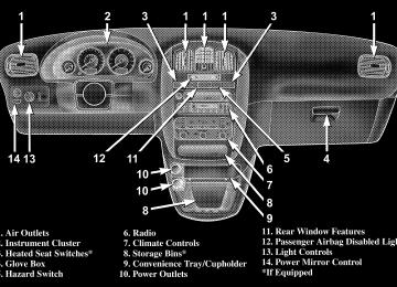
INSTRUMENTS AND CONTROLS
UNDERSTANDING YOUR INSTRUMENT PANEL 195
196 UNDERSTANDING YOUR INSTRUMENT PANEL
BASE INSTRUMENT CLUSTER
INSTRUMENT CLUSTER WITH TACH
UNDERSTANDING YOUR INSTRUMENT PANEL 197
198 UNDERSTANDING YOUR INSTRUMENT PANEL
PREMIUM INSTRUMENT CLUSTER
INSTRUMENT CLUSTER DESCRIPTIONS
1. Fuel Gauge The pointer shows the level of fuel in the fuel tank when the ignition switch is in the ON position. 2. Tire Pressure Monitor Warning Light — If Equipped This light will turn on when there is a Low tire pressure condition. The light will remain on until the tire pressure is properly set. The light will also flash if a problem exist with any tire sensor. The light will flash for approximately three sec- onds every 10 minutes or until the problem with the sensor is corrected. This light will turn on momentarily as a bulb check when the engine is started. When the tire pressure monitoring system warning light is lit, one or more of your tires is significantly underin- flated. You should stop and check your tires as soon as
UNDERSTANDING YOUR INSTRUMENT PANEL 199
possible, and inflate them to the proper pressure as indicated on the tire and loading information placard. Driving on a significantly underinflated tire causes the tire to overheat and can lead to tire failure. Underinfla- tion also reduces fuel efficiency and tire tread life, and may affect the vehicle’s handling and stopping ability. Each tire, including the spare, should be checked monthly when cold and set to the recommended inflation pressure as specified in the tire and loading information placard and owner’s manual. If one of the vehicle active tires has been NOTE: replaced by the spare or a wheel rim not equipped with a TPM sensor, the tire pressure monitor warning light will flash for approximately three seconds every 10
minutes. Repair or replace the tire or sensor as soon as possible.200 UNDERSTANDING YOUR INSTRUMENT PANEL
3. Low Fuel Light
When the fuel level reaches approximately 3.0
gallons (11.0 liters) this light will turn on and remain on until fuel is added.4. Turn Signal Indicators
The arrow will flash with the exterior turn signal when the turn signal lever is operated.
If the vehicle electronics sense that the vehicle has traveled about one mile with the turn signals on, a chime will sound to alert you to turn the signals off. If either indicator flashes at a rapid rate, check for a defective outside light bulb. 5. Liftgate Ajar
This light turns on if the liftgate is not com- pletely closed.
6. Door Ajar Light
This light turns on if a door is not completely closed.
7. Speedometer Indicates vehicle speed. 8. Brake System Warning Light
This light monitors various brake functions, including brake fluid level and parking brake application. If the brake light turns on, it may indicate that the parking brake is applied, there is a low brake fluid level or there is a problem with the anit-lock brake system. The dual brake system provides a reserve braking capac- ity in the event of a failure to a portion of the hydraulic system. Failure of either half of the dual brake system is indicated by the Brake Warning Light which will turn on when the brake fluid level in the master cylinder has dropped below a specified level.
The light will remain on until the cause is corrected. NOTE: The light may flash momentarily during sharp cornering maneuvers which change fluid level condi- tions. The vehicle should have service performed. If brake failure is indicated, immediate repair is neces- sary.
WARNING!
Driving a vehicle with the brake light on is danger- ous. Part of the brake system may have failed. It will take longer to stop the vehicle. You could have an accident. Have the vehicle checked immediately.
Vehicles equipped with Anti-Lock brakes (ABS), are also equipped with Electronic Brake Force Distribution (EBD).
UNDERSTANDING YOUR INSTRUMENT PANEL 201
In the event of an EBD failure, the Brake Warning Light will turn on along with the ABS Light. Immediate repair to the ABS system is required. The operation of the Brake Warning Light can be checked by turning the ignition switch from the OFF position to the ON position. The light should illuminate for approxi- mately four seconds. The light should then turn off unless the parking brake is applied or a brake fault is detected. If the light does not illuminate, have the light inspected by an authorized dealer. The light also will turn on when the parking brake is applied with the ignition switch in the ON position. NOTE: This light shows only that the parking brake is applied. It does not show the degree of brake application.
202 UNDERSTANDING YOUR INSTRUMENT PANEL
9. Airbag Light
This light turns on and remains on for 6 to 8
seconds as a bulb check when the ignition switch is first turned ON. If the light is not on during starting, stays on, or turns on while driving, have the system inspected by an authorized dealer as soon as possible. 10. Anti-Lock LightThis light monitors the Anti-Lock Brake Sys- tem. The light will turn on when the ignition switch is turned to the ON position and may stay on for as long as four seconds.
If the ABS light remains on or turns on while driving, it indicates that the Anti-Lock portion of the brake system is not functioning and that service is required. However, the conventional brake system will continue to operate normally if the BRAKE warning light is not on.
If the ABS light is on, the brake system should be serviced as soon as possible to restore the benefits of Anti-Lock brakes. If the ABS light does not turn on when the Ignition switch is turned to the ON position, have the light inspected by an authorized dealer. 11. Tachometer — If Equipped The red segments indicate the maximum permissible engine revolutions-per-minute (r.p.m. x 1000) for each gear range. Before reaching the red area, ease up on the accelerator. 12. Voltage Light
This light monitors the electrical system voltage. The light should turn on momentarily as the engine is started. If the light stays on or turns on while driving, it indicates a problem with the charging system. Immediate service should be obtained.
13. Seat Belt Reminder Light
When the ignition switch is first turned ON, this light will turn on for 5 to 8 seconds as a bulb check. During the bulb check, if the driver’s seat belt is unbuckled, a chime will sound. After the bulb check or when driving, if the driver seat belt remains unbuckled, the Seat Belt Warning Light will flash or remain on continuously. Refer to ⬙Enhanced Driver Seat Belt Re- minder System (BeltAlert™)⬙ in the Occupant Restraints section for more information. 14. Engine Temperature Warning Light
This light warns of an overheated engine condi- tion. If the engine is critically hot, a continuous chime will sound for 4 minutes. After the chime turns off, the engine will still be critically hot until the light turns off.
UNDERSTANDING YOUR INSTRUMENT PANEL 203
15. Vehicle Theft Alarm Light — If Equipped
This light will flash for approximately 15 sec- onds when the vehicle theft alarm is arming.
16. Temperature Gauge The temperature gauge shows engine coolant tempera- ture. Any reading within the normal range indicates that the engine cooling system is operating satisfactorily. The gauge pointer will likely indicate a higher tempera- ture when driving in hot weather, up mountain grades, or when towing a trailer. It should not be allowed to exceed the upper limits of the normal operating range.
204 UNDERSTANDING YOUR INSTRUMENT PANEL
CAUTION!
WARNING!
Driving with a hot engine cooling system could damage your vehicle. If temperature gauge reads (H), pull over and stop the vehicle. Idle the vehicle with the air conditioner turned off until the pointer drops back into the normal range. If the pointer remains on the “H”, and you hear continuous chimes, turn the engine off immediately, and call for service.
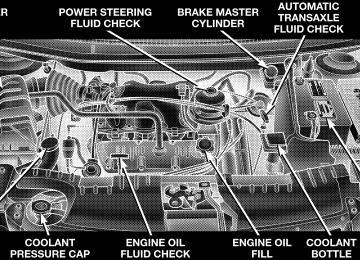
A hot engine cooling system is dangerous. You or others could be badly burned by steam or boiling coolant. You may want to call a service center if your vehicle overheats. If you decide to look under the hood yourself, see Section 7 of this manual. Follow the warnings under the Cooling System Pressure Cap paragraph.
17. Washer Fluid Light
This light turns on when the washer fluid level falls below approximately 1/4 filled. The light will remain on until fluid is added.
18. Transmission Range Indicator This display indicator shows the automatic transaxle gear selection.
NOTE: You must apply the brakes before shifting from Park. 19. Oil Pressure Warning Light
This light shows low engine oil pressure. The light should turn on momentarily when the engine is started. If the light turns on while driving, stop the vehicle and shut off the engine as soon as possible. A chime will sound for 4 minutes when this light turns on. Do not operate the vehicle until the cause is corrected. This light does not show how much oil is in the engine. The engine oil level must be checked under the hood. 20. High Beam Light
This light shows that the headlights are on high beam. Pull lever towards the steering wheel to switch the headlights from high or low beam.
the turn signal
UNDERSTANDING YOUR INSTRUMENT PANEL 205
21. Malfunction Indicator Light
This light is part of an onboard diagnostic system called OBD that monitors engine and automatic transmission control systems. The light will illu- minate when the key is in the ON position before engine start. If the bulb does not come when turning the key from OFF to ON, have the condition checked promptly. Certain conditions such as a loose or missing gas cap, poor fuel quality, etc. may illuminate the light after engine start. The vehicle should be serviced if the light stays on through several of your typical driving cycles. In most situations the vehicle will drive normally and will not require towing. The Malfunction Indicator Light flashes to alert to serious conditions that could lead to immediate loss of power or severe catalytic converter damage. The vehicle should be serviced as soon as possible if this occurs.
206 UNDERSTANDING YOUR INSTRUMENT PANEL
22. Trac Off Indicator — If Equipped This display indicator should illuminate for approxi- mately four seconds as a bulb check when the ignition switch is first turned ON. The “TRAC OFF” Indicator will flash if the traction control is in use. The “TRAC OFF” Indicator will illuminate if: • The Traction Control switch has been used to turn • There is a Traction Control System malfunction • The system has been deactivated to prevent damage to the brake system due to overheated brake tem- peratures.
the system OFF.
NOTE: Extended heavy use of Traction Control may cause the system to deactivate and turn on the TRAC and the OFF indicators located in the instrument cluster.
This is to prevent overheating of the brake system and is a normal condition. The system will remain disabled for about 4 minutes until the brakes have cooled. The system will automatically reactivate and turn off the TRAC and the OFF indicators. If your vehicle becomes stuck in mud, ice, or snow, turn the Traction Control System OFF before attempting to “rock” the vehicle free. 23. Odometer/Trip Odometer The odometer shows the total distance the vehicle has been driven. U.S. federal regulations require that upon transfer of vehicle ownership, the seller certify to the purchaser the correct mileage that the vehicle has been driven. There- fore, if the odometer reading is changed during repair or replacement, be sure to keep a record of the reading before and after the service so that the correct mileage can be determined.
The trip odometer shows individual trip mileage. To switch from odometer to trip odometer, press the Trip Odometer button. 24. Cruise Indicator This display indicator shows that the Speed Control System is ON. 25. Trip Odometer Button Press this button to change the display from odometer to trip odometer. The word TRIP will appear when in the trip odometer mode. Push in and hold the button for two seconds to reset the trip odometer to 0 miles or kilometers. The odometer must be in trip mode to reset.
UNDERSTANDING YOUR INSTRUMENT PANEL 207
ELECTRONIC DIGITAL CLOCK
The clock and radio each use the display panel built into the radio. A digital readout shows the time in hours and minutes whenever the ignition switch is in the ON or ACC position and the time button is pressed. When the ignition switch is in the OFF position, or when the radio frequency is being displayed, time keeping is accurately maintained. Clock Setting Procedure
1. Turn the ignition switch to the ON or ACC position and press the time button. Using the tip of a ballpoint pen or similar object, press either the hour (H) or minute (M) buttons on the radio. 2. Press the H button to set hours or the M button to set minutes. The time setting will increase each time you press a button.
208 UNDERSTANDING YOUR INSTRUMENT PANEL
RADIO GENERAL INFORMATION
Radio Broadcast Signals Your new radio will provide excellent reception under most operating conditions. Like any system, however, car radios have performance limitations, due to mobile op- eration and natural phenomena, which might lead you to believe your sound system is malfunctioning. To help you understand and save you concern about these “ap- parent” malfunctions, you must understand a point or two about the transmission and reception of radio sig- nals. Two Types of Signals There are two basic types of radio signals... AM or Amplitude Modulation, in which the transmitted sound causes the amplitude, or height, of the radio waves to vary... and FM or Frequency Modulation, in which the frequency of the wave is varied to carry the sound.
Electrical Disturbances Radio waves may pick up electrical disturbances during transmission. They mainly affect the wave amplitude, and thus remain a part of the AM reception. They interfere very little with the frequency variations that carry the FM signal. AM Reception AM sound is based on wave amplitude, so AM reception can be disrupted by such things as lightning, power lines and neon signs. FM Reception Because FM transmission is based on frequency varia- tions, interference that consists of amplitude variations can be filtered out, leaving the reception relatively clear, which is the major feature of FM radio. NOTE: On vehicles so equipped the radio, steering wheel radio controls and 6 disc CD/DVD changer will
remain active for up to 45 seconds after the ignition switch has been turned off. Opening a vehicle front door will cancel this feature.
SALES CODE RAZ—AM/ FM STEREO RADIO WITH CASSETTE TAPE PLAYER, CD PLAYER AND CD CHANGER CONTROLS
RAZ Radio
UNDERSTANDING YOUR INSTRUMENT PANEL 209
Operating Instructions — Radio
NOTE: Power to operate the radio is controlled by the ignition switch. It must be in the ON or ACC position to operate the radio. Power Switch, Volume Control Press the ON/VOL control to turn the radio on. Turn the volume control clockwise to increase the volume. The volume will be displayed and continuously updated while the button is pressed. Seek Button (Radio Mode) Press and release the Seek button to search for the next station in either the AM or FM mode. Press the top of the button to seek up and the bottom to seek down. Holding the button will by pass stations until you release the button.
210 UNDERSTANDING YOUR INSTRUMENT PANEL
Tuning Press the TUNE control up or down to increase or decrease the frequency. If you press and hold the button, the radio will continue to tune until you release the button. The frequency will be displayed and continu- ously updated while the button is pressed. Radio Data System (RDS)
The Radio Data System allows radio broadcasting sta- tions to send data signals on a subcarrier frequency which is added to the stereo signal. RDS was developed to give FM receivers user-friendly features, such as Program Service name (PS) and Program Type (PTY). Program Service name is typically used by the broad- caster to display the station’s name or call letters, for
example ⬙WNIC⬙. Typically these are 8 characters in length and are displayed by the radio for those stations which are broadcasting this information. PTY (Program Type) is used to characterize the station’s program ma- terial, for example ⬙Rock Music⬙. PTY (Program Type) Button Pressing this button once will turn on the PTY mode for 5 seconds. If no action is taken during the 5 second time out the PTY icon will turn off. Pressing the PTY button within 5 seconds will allow the program format type to be selected. Many radio stations do not currently broad- cast PTY information.
Toggle the PTY button to select the following format types:
Program Type
Radio Display
Adult Hits Classical Classic Rock College Country Information Jazz Foreign Language News Nostalgia Oldies Personality Public Rhythm and Blues
Adlt Hit Classicl Cls Rock College Country Inform Jazz Language News Nostalga Oldies Persnlty Public R & B
UNDERSTANDING YOUR INSTRUMENT PANEL 211
Program Type
Radio Display
Rel Musc Rel Talk Rock Soft Soft Rck Soft R&B Sports Talk Top 40
WeatherReligious Music Religious Talk Rock Soft Soft Rock Soft Rhythm and Blues Sports Talk Top 40
Weather By pressing the SEEK button when the PTY icon is displayed, the radio will be tuned to the next frequency station with the same selected PTY name. The PTY function only operates when in the FM mode. The radio display will flash “SEEK” and the selected PTY program type when searching for the next PTY station. If212 UNDERSTANDING YOUR INSTRUMENT PANEL
no station is found with the selected PTY program type, the radio will return to the last preset station. If a preset button is activated while in the PTY (Program Type) mode, the PTY mode will be exited and the radio will tune to the preset station. Pressing PTY, then SCAN will scan the FM Band and stop at all RDS stations. Each RDS station will be played for a 5 second scan once around the FM Band and stop at the last station. The PTY icon will then turn off. Balance The Balance control adjusts the left-to-right speaker bal- ance. Push in the button and it will pop out. Adjust the balance and push the button back in. The balance will be displayed and continuously updated while the button is turned.
Fade The Fade control provides for balance between the front and rear speakers. Push in the button and it will pop out. Adjust the balance and push the button back in. The fade will be displayed and continuously updated while the button is turned. Tone Control Slide the Bass and/or Treble controls up or down to adjust the sound for the desired tone. The treble, and bass will be displayed and continuously updated while the slide is moved. AM/FM Selection Press the AM/FM button to change from AM to FM. The operating mode will be displayed next to the station frequency. The display will show ST when a stereo station is received.
Scan Button Pressing the SCAN button causes the tuner to search for the next station, in either AM or FM, pausing for 5
seconds at each listenable station before continuing to the next. Pressing the AM/FM button continues the search in the alternate frequency band. To stop the search, press SCAN a second time. To Set The Radio Push-button Memory When you are receiving a station that you wish to commit to push-button memory, press the SET button. SET 1 will show in the display window. Select the push-button you wish to lock onto this station and press and release that button. If a station is not selected within 5 seconds after pressing the SET button, the station will continue to play but will not be locked into push-button memory.UNDERSTANDING YOUR INSTRUMENT PANEL 213
You may add a second station to each push-button by repeating the above procedure with this exception: Press the SET button twice and SET 2 will show in the display window. Each button can be set for SET 1 and SET 2 in both AM and FM. This allows a total of 10 AM and 10 FM stations to be locked into memory. You can recall the stations stored in SET 2 memory by pressing the push- button twice. To Change From Clock To Radio Mode Press the Time button to change the display between radio frequency and time. Operating Instructions — Tape Player Insert the cassette with the exposed tape side toward the right and the mechanical action of the player will gently pull the cassette into the play position. NOTE: When subjected to extremely cold temperatures, the tape mechanism may require a few minutes to warm up for proper operation. Sometimes poor playback may
214 UNDERSTANDING YOUR INSTRUMENT PANEL
be experienced due to a defective cassette tape. Clean and demagnetize the tape heads at least twice a year. Seek Button Press the SEEK button up for the next selection on the tape and down to return to the beginning of the current selection. Press the SEEK button up or down to move the track number to skip forward or backward 1 to 6 selections. Press the SEEK button once to move 1 selection, twice to move 2 selections, etc. Fast Forward (FF) Press the FF button up momentarily to advance the tape in the direction that it is playing. The tape will advance until the button is pressed again or the end of the tape is reached. At the end of the tape, the tape will play in the opposite direction.
Rewind (RW) Press the RW button momentarily to reverse the tape direction. The tape will reverse until the button is pressed again or until the end of the tape is reached. At the end of the tape, the tape will play in the opposite direction. Tape Eject Press the EJT Tape button and the cassette will disengage and eject from the radio. Scan Button Press this button to play 10 seconds of each selection. Press the scan button a second time to cancel the feature. Changing Tape Direction If you wish to change the direction of tape travel (side being played), press the PTY button. The lighted arrow in the display window will show the new direction.
Metal Tape Selection If a standard metal tape is inserted into the player, the player will automatically select the correct equalization and the 70 symbol will appear in the display window. Pinch Roller Release If ignition power or the radio ON/OFF switch are turned off, the pinch roller will automatically retract to protect the tape from any damage. When power is restored to the tape player, the pinch roller will automatically reengage and the tape will resume play. Noise Reduction The Dolby Noise Reduction System* is on whenever the tape player is on, but may be switched off. To turn off the Dolby Noise reduction System: Press the Dolby button (button 2) after you insert the tape. The NR light in the display will go off when the Dolby System is off. The Dolby System is automatically reactivated each time a tape is inserted.
UNDERSTANDING YOUR INSTRUMENT PANEL 215
* ”Dolby” noise reduction manufactured under license from Dolby Laboratories Licensing Corporation. Dolby and the double-D symbol are trademarks of Dolby Labo- ratories Licensing Corporation. Operating Instructions — CD Player
NOTE: The ignition switch must be in the ON or ACC position and the volume control ON before the CD player will operate.
CAUTION!
This CD player will accept 4 3⁄4 inch (12 cm) discs only. The use of other sized discs may damage the CD player mechanism.
216 UNDERSTANDING YOUR INSTRUMENT PANEL
Inserting The Compact Disc The CD player contained within the radio is not a multi-disc changer, and will only accept one CD. Gently insert one CD into the CD player with the CD label facing up. The CD will automatically be pulled into the CD Player. If the volume control is ON, the unit will switch from radio to CD mode and begin to play. The display will show the track number and index time in minutes and seconds. Play will begin at the start of track one. NOTE: • You may eject a disc with the radio OFF. The ignition switch must be in the ON or ACC position to insert a disc with the radio OFF. • If you insert a disc with the ignition ON and the radio OFF, the CD will automatically be pulled into the CD Player and the display will show the time of day. If
you insert a disc with the ignition OFF, the display will show the time of day for about 5 seconds, then go out.
Seek Button Press the top of the SEEK button for the next selection on the CD. Press the bottom of the button to return to the beginning of the current selection, or return to the beginning of the previous selection if the CD is within the first 10 seconds of the current selection. EJT CD (Eject) Button Press this button and the disc will unload and move to the entrance for easy removal. The unit will switch to the radio mode. If you do not remove the disc within 15 seconds, it will be reloaded. The radio mode will continue to appear. The disc can be ejected with the radio OFF.
FF/TUNE/RW Press FF (Fast Forward) and the CD player will begin to fast forward until FF is released. The RW ( Reverse) button works in a similar manner. Program Button 4 (Random Play) Press this button while the CD is playing to activate Random Play. This feature plays the tracks on the se- lected disc in random order to provide an interesting change of pace. Press the SEEK button to move to the next randomly selected track. Press TUNE FF to fast forward through the tracks. Press the FF button a second time to stop the fast forward feature. If TUNE RW is pressed, the current track will reverse to the beginning of the track and begin playing. Press button 4 a second time to stop Random Play.
UNDERSTANDING YOUR INSTRUMENT PANEL 217
MODE Press the MODE button to select between the tape player, CD player, or satellite radio (if equipped). To select Satellite Radio (if equipped), press the MODE button until the word SIRIUS appears. The following will be displayed in this order: After three seconds, the current channel name and number will be displayed for five seconds. The current program type and channel number will then be displayed for five seconds. The current channel name and number will then be displayed until an action occurs. A CD or tape may remain in the player while in the Satellite Radio mode. Tape CD Button Press this button to select between CD player and Tape player.
218 UNDERSTANDING YOUR INSTRUMENT PANEL
Time Button Press this button to change the display from elapsed CD playing time to time of day. Scan Button Press this button to play the first 10 seconds of each track. To stop the scan function, press the button a second time. CD Changer Control Capability — If Equipped This radio is compatible with a remote mounted CD changer available through Mopar Accessories. The fol- lowing instructions are for the radio controls that operate this CD changer. Mode Button To activate the CD changer, press the MODE button until CD information appears on the display. Disc Up/Program Button 1
Press the DISC up (button 1) button to play the next available disc.Disc Down/Program Button 5
Press the DISC down (button 5) button to play the previous disc. Seek Button Press the SEEK up or down to select another track on the same disc. A SEEK symbol will appear on the display. Fast Forward And Rewind Buttons Press and hold the FF button for fast forward. Press and hold the RW button for fast reverse. The audio output can be heard when fast forward and fast reverse are activated. Random Play (RND) Press the Random button to play the tracks on the selected disc in random order for an interesting change of pace. Random can be cancelled by pressing the button a second time or by ejecting the CD from the changer.CD Diagnostic Indicators When driving over a very rough road, the CD player may skip momentarily. Skipping will not damage the disc or the player, and play will resume automatically. As a safeguard and to protect your CD player, one of the following warning symbols may appear on your display. A CD HOT symbol indicates the player is too hot. CD HOT will pause the operation. Play can be resumed when the operating temperature is corrected or another MODE is selected. An ERR symbol will appear on the display if the laser is unable to read the Disc data for the following reasons: • Excessive vibration • Disc inserted upside down • Damaged disc
UNDERSTANDING YOUR INSTRUMENT PANEL 219
• Water condensation on optics SALES CODE RBP—AM & FM STEREO RADIO WITH CASSETTE TAPE PLAYER, CD PLAYER, AND OPTIONAL CD/DVD CHANGER CONTROLS
RBP Radio
220 UNDERSTANDING YOUR INSTRUMENT PANEL
Radio Operation
Power/Volume Control Press the ON/VOL control to turn the radio on. Turn the volume control to the right to increase the volume. NOTE: Power to operate the radio is supplied through the ignition switch. It must be in the ON or ACC position to operate the radio. PTY (Program Type) Button Pressing this button once will turn on the PTY mode for 5 seconds. If no action is taken during the 5 second time out the PTY icon will turn off. Pressing the PTY button within 5 seconds will allow the program format type to be selected. Many radio stations do not currently broad- cast PTY information. Toggle the PTY button to select the following format types:
Program Type
Radio Display
Adult Hits Classical Classic Rock College Country Information Jazz Foreign Language News Nostalgia Oldies Personality Public Rhythm and Blues Religious Music Religious Talk
Adlt Hit Classicl Cls Rock College Country Inform Jazz Language News Nostalga Oldies Persnlty Public R & B Rel Musc Rel Talk
Program Type
Radio Display
Rock Soft Soft Rck Soft R&B Sports Talk Top 40
WeatherRock Soft Soft Rock Soft Rhythm and Blues Sports Talk Top 40
Weather By pressing the SEEK button when the PTY icon is displayed, the radio will be tuned to the next frequency station with the same selected PTY name. The PTY function only operates when in the FM and Satellite (if equipped) modes. The radio display will flash “SEEK” and the selected PTY program type when searching for the next PTY station. IfUNDERSTANDING YOUR INSTRUMENT PANEL 221
no station is found with the selected PTY program type, the radio will return to the last preset station. If a preset button is activated while in the PTY (Program Type) mode, the PTY mode will be exited and the radio will tune to the preset station. Pressing PTY, then SCAN will scan the FM Band and stop at all RDS stations that broadcast the station type. Each RDS station will be played for a 5 second scan once around the FM Band and stop at the last station. The PTY icon will then turn off. Seek Press and release the SEEK button to search for the next station in either the AM or FM mode. Press the top of the button to seek up and the bottom to seek down. The radio will remain tuned to the new station until you make another selection. Holding the button in will by- pass stations without stopping until you release it.
222 UNDERSTANDING YOUR INSTRUMENT PANEL
Scan Press and release the SCAN button to search for the next station in either the AM or FM mode. The radio will pause for 5 seconds at each listenable station before continuing to the next. To stop the search, press the SCAN button a second time. Tune Press the TUNE control up or down to increase or decrease the frequency. If you press and hold the button, the radio will continue to tune until you release the button. The frequency will be displayed and continu- ously updated while the button is pressed. Balance — BAL The Balance control adjusts the left-to-right speaker bal- ance. Press the BAL button in and it will pop out. Adjust the balance and push the button back in.
Fade The Fade control provides for balance between the front and rear speakers. Press the FADE button in and it will pop out. Adjust the balance and push the button back in. Tone Control The tone controls affect the BASS and TREBLE frequency bands. Each is controlled by a slider control with a detent at the mid position. Moving a control up or down increases or decreases amplification of the band. The mid position provides a balanced output. AM/FM Selection Press the AM/FM button to toggle between AM and FM mode. The operating mode will be displayed next to the station frequency. The display will show “ST” when a stereo station is received (FM only). To Set The Radio Push-Button Memory When you are receiving a station that you wish to commit to push-button memory, press the SET button.
SET 1 will now show in the display window. Select the “1–5” button you wish to lock onto this station and press and release that button. If a button is not selected within 5 seconds after pressing the SET button, the station will continue to play but will not be locked into push-button memory. You may add a second station to each push-button by repeating the above procedure with this exception: Press the SET button twice and SET 2 will show in the display window. Each button can be set for SET 1 and SET 2 in both AM and FM. This allows a total of 10 AM and 10 FM stations to be locked into push-button memory. The stations stored in SET 2 memory can be selected by pressing the push-button twice. Time Press the TIME button to change the display between radio frequency and time.
UNDERSTANDING YOUR INSTRUMENT PANEL 223
To set the clock, use a ballpoint pen or similar object to press the hour (H) or minute (M) buttons on the radio, The time setting will increase each time you press the button. Press any other button to exit from the clock setting mode. General Information This radio complies with Part 15 of FCC rules and with RSS-210 of Industry Canada. Operation is subject to the following conditions: 1. This device may not cause harmful interference, 2. This device must accept any interference received, including interference that may cause undesired opera- tion. NOTE: Changes or modifications not expressively ap- proved by the party responsible for compliance could void the user’s authority to operate the equipment.
224 UNDERSTANDING YOUR INSTRUMENT PANEL
Tape Player Operation Insert the cassette with the exposed tape side toward the right and the mechanical action of the player will gently pull the cassette into the play position. NOTE: When subjected to extremely cold temperatures, the tape mechanism may require a few minutes to warm up for proper operation. Sometimes poor playback may be experienced due to a defective cassette tape. Clean and demagnetize the tape heads at least twice a year. Tape Side — ⵜ⌬/PTY Pressing the ⵜ⌬ button during tape mode will cause the other side of the tape to be played. The display will confirm the selected tape play direction. The time is always displayed. Tape Press the TAPE button to select the Tape mode.
Seek Press the SEEK button up for the next selection on the tape and down to return to the beginning of the current selection. Press the SEEK button up or down to move the track number to skip forward or backward 1 to 7 selections. Press the SEEK button once to move 1 selection, twice to move 2 selections, etc. the display will show the total number of times the SEEK button was pushed. The SEEK function will be cancelled by pressing either the FF/RW or AM/FM button. Fast Forward — FF Press the FF button up momentarily to advance the tape in the direction that it is playing. The tape will advance until the button is pressed again or the end of the tape is reached. At the end of the tape, the tape will play in the opposite direction.
Rewind — RW Press the RW button down momentarily to reverse the tape direction. The tape will rewind until the button is pressed again or until the beginning of the tape is reached. At the beginning of the tape, the tape will play in the opposite direction. EJT Tape Press the EJT TAPE button and the cassette will disen- gage and eject from the radio. Metal Tape Selection (70µs) If a standard 70 µ (metal) tape is inserted into the player, the player will automatically select the correct equaliza- tion. Pinch Roller Release If ignition power or the radio ON/OFF switch are turned off, the pinch roller will automatically retract to protect
UNDERSTANDING YOUR INSTRUMENT PANEL 225
the tape from any damage. When power is restored to the tape player, the pinch roller will automatically reengage and the tape will resume play. Dolby Noise Reduction
The Dolby Noise Reduction System* is on when- ever the tape player is on, but may be switched
on/off. To turn the Dolby Noise Reduction System on/off: Press the Dolby NR button (button 2) after you insert the tape. The NR light in the display will go off when the Dolby System is off. * ”Dolby” noise reduction manufactured under license from Dolby Laboratories Licensing Corporation. Dolby and the double-D symbol are trademarks of Dolby Labo- ratories Licensing Corporation.
226 UNDERSTANDING YOUR INSTRUMENT PANEL
CD Player Operation
NOTE: The ignition switch must be in the ON or ACC position and the volume control ON before the CD player will operate. Inserting The Compact Disc You may either insert or eject a disc with the radio OFF. If you insert a disc with the ignition ON and the radio off, the display will show CD and the time of day will be displayed. If the power is on, the unit will switch from radio to CD mode and begin to play when you insert the disc. The display will show the track number and index time in minutes and seconds. Play will begin at the start of track one. Seek Press the top of the SEEK button for the next selection on the CD. Press the bottom of the button to return to the
beginning of the current selection, or return to the beginning of the previous selection if the CD is within the first second of the current selection. Scan Press the SCAN button to play 10 seconds of each selection. Press the SCAN button a second time to cancel this feature. EJT CD Press the EJT CD button and the disc will unload and move to the entrance for easy removal. The unit will switch to the radio mode. If you do not remove the disc within 15 seconds, it will be reloaded. The unit will continue in radio mode. The disc can be ejected with the radio and ignition off.
FF/TUNE/RW Press FF (Fast Forward) and the CD player will begin to fast forward until FF is released. The RW (Reverse) button works in a similar manner. Random Play — RND/Program Button 4
Press the RND (button 4) button while the CD is playing to activate Random Play. This feature plays the selections on the compact disc in random order to provide an interesting change of pace. Press the top of the SEEK button to move to the next randomly selected track. Press the RND (button 4) button a second time to stop Random Play. MODE Press the MODE button to select between the CD player, remote CD/DVD changer (if equipped), or satellite radio (if equipped).UNDERSTANDING YOUR INSTRUMENT PANEL 227
To select Satellite Radio (if equipped), press the MODE button until the word SIRIUS™ appears. The following will be displayed in this order: After three seconds, the current channel name and number will be displayed for five seconds. The current program type and channel number will then be displayed for five seconds. The current channel name and number will then be displayed until an action occurs. A CD or tape may remain in the player while in the Satellite Radio mode. Time Press the TIME button to change the display from elapsed CD playing time to time of day. CD/DVD Changer Operation — If Equipped
MODE Press the MODE button to select between the CD player, and the CD/DVD changer (if equipped).
228 UNDERSTANDING YOUR INSTRUMENT PANEL
Disc Up/Program Button 1
Press the DISC (button 1) button to play the next avail- able disc. Random Play — RND/Program Button 4
Press the RND (button 4) button while the CD is playing to activate Random Play. This feature plays the selections on the currently playing compact disc in random order to provide an interesting change of pace. Press the top of the SEEK button to move to the next randomly selected track. Press the RND (button 4) button a second time to stop Random Play. FF/RW — TUNE Press and hold the FF button for fast forward. Press and hold the RW button for fast reverse. The audio output can be heard when fast forward and fast reverse are acti- vated.Disc Down/Program Button 5
Press the DISC (button 5) button to play the previous disc. Seek Press the top of the SEEK button for the next selection on the CD. Press the bottom of the button to return to the beginning of the current selection, or return to the beginning of the previous selection if the CD is within the first second of the current selection. Time Press the TIME button to switch between time of day and CD track time. Scan Press the SCAN button to play 10 seconds of each track. Press the SCAN button a second time to cancel the feature.SALES CODE RBQ—AM/FM STEREO RADIO WITH 6 - DISC CD CHANGER
RBQ Radio
UNDERSTANDING YOUR INSTRUMENT PANEL 229
Radio Operation
Power/Volume Control Press the PWR/VOL control to turn the radio on. Turn the volume control clockwise to increase the volume. NOTE: Power to operate the radio is controlled by the ignition switch. It must be in the ON or ACC position to operate the radio. Mode Press the MODE button repeatedly to select between AM, FM, the CD changer and Sirius Satellite Radio™ (if equipped). The display will show ST when a stereo station is received. To select Sirius Satellite Radio™ (if equipped), press the MODE button until the word SIRIUS appears. The fol- lowing will be displayed in this order: After three sec- onds, the current channel name and number will be displayed for five seconds. The current program type and
230 UNDERSTANDING YOUR INSTRUMENT PANEL
channel number will then be displayed for five seconds. The current channel name and number will then be displayed until an action occurs. CD’s may remain in the player while in the Satellite Radio mode. Seek Press and release the SEEK button to search for the next station in either the AM or FM mode. Press the top of the button to seek up and the bottom to seek down. The radio will remain tuned to the new station until you make another selection. Holding the button in will by- pass stations without stopping until you release it. Tune Press the TUNE control up or down to increase or decrease the frequency. If the button is pressed and held, the radio will continue to tune until the button is released. The frequency will be displayed and continu- ously updated while the button is pressed.
To Set The Radio Push-Button Memory When you are receiving a station that you wish to commit to push-button memory, press the SET RND button. SET 1 will show in the display window. Select the “1–6” button you wish to lock onto this station and press and release that button. If a button is not selected within 5 seconds after pressing the SET RND button, the station will continue to play but will not be locked into push- button memory. You may add a second station to each push-button by repeating the above procedure with this exception: Press the SET button twice and SET 2 will show in the display window. Each button can be set for SET 1 and SET 2 in both AM and FM. This allows a total of 12 AM and 12 FM stations to be locked into push-button memory. The stations stored in SET 2 memory can be selected by pressing the corresponding push-button twice. Every time a preset button is used, a corresponding button number will be displayed.
Audio The audio button controls the BASS, TREBLE, BAL- ANCE, and FADE. Press the AUDIO button and BASS will be displayed. Press the SEEK + or SEEK – to increase or decrease the Bass tones. Press the AUDIO button a second time and TREB will be displayed. Press the SEEK + or SEEK – to increase or decrease the Treble tones. Press the AUDIO button a third time and BAL will be displayed. Press the SEEK + or SEEK – to adjust the sound level from the right or left side speakers. Press the AUDIO button a fourth time and FADE will be displayed. Press the SEEK + or SEEK – to adjust the sound level between the front and rear speakers. Press the AUDIO button again or wait 5 seconds to exit setting tone, balance, and fade.
UNDERSTANDING YOUR INSTRUMENT PANEL 231
Time Button Press the TIME button to change the display between radio frequency and time. General Information This radio complies with Part 15 of FCC rules and with RSS-210 of Industry Canada. Operation is subject to the following conditions: 1. This device may not cause harmful interference, 2. This device must accept any interference received, including interference that may cause undesired opera- tion. NOTE: Changes or modifications not expressively ap- proved by the party responsible for compliance could void the user’s authority to operate the equipment.
232 UNDERSTANDING YOUR INSTRUMENT PANEL
CD Player Operation
NOTE: The ignition switch must be in the ON or ACC position and the Power / Volume control pushed ON before the CD player will operate. Inserting The Compact Disc
CAUTION!
This CD player will accept 4 3⁄4 inch (12 cm) discs only. The use of other sized discs may damage the CD player mechanism.
You may either insert or eject a disc with the radio OFF. If you insert a disc with the ignition ON and the radio OFF, the display will show the time of day. If you insert a disc with the ignition OFF, the display will show the time of day for about 5 seconds, then go out.
If you insert a disc with the ignition ON and the radio ON, the unit will switch from radio to CD mode and begin to play when you insert the disc. The display will show the disc number, the track number, and index time in minutes and seconds. Play will begin at the start of track 1. LOAD/ EJT — Load Press the LOAD/ EJT button and the button with the corresponding number where the CD is being loaded. After the radio displays “load” insert the CD into the player. Radio display will show “loading” when it is being loaded. LOAD / EJT — Eject Press the LOAD/ EJT button and the button with the corresponding number where the CD was loaded and the disc will unload and move to the entrance for easy removal.
Radio display will show “ejecting” when it is being ejected. If you have ejected a disc and have not removed it within 15 seconds, it will be reloaded. If the CD is not removed, the radio will continue to play the non-removed CD. If the CD is removed and there are other CD’s in the radio, the radio will play the next CD. If the CD is removed and there are no other CD’s in the radio, the radio will return to the last selected AM or FM mode. The disc can be ejected with the radio and ignition OFF. Seek Press the top of the SEEK button for the next selection on the CD. Press the bottom of the button to return to the beginning of the current selection, or return to the beginning of the previous selection if the CD is within the first second of the current selection.
UNDERSTANDING YOUR INSTRUMENT PANEL 233
Scan Press the Scan button to scan through each track on the CD currently playing. FF/TUNE/RW Press FF (Fast Forward) and the CD player will begin to fast forward until FF is released. The RW ( Reverse) button works in a similar manner. Random Play — SET / RND Press the RND button while the CD is playing to activate Random Play. This feature plays the tracks on the disc in random order to provide an interesting change of pace. Press the SEEK button to move to the next randomly selected track. Press the SET / RND button a second time to stop Random Play.
234 UNDERSTANDING YOUR INSTRUMENT PANEL
PTY (Program Type) Button Pressing this button once will turn on the PTY mode for 5 seconds. If no action is taken during the 5 second time out the PTY icon will turn off. Pressing the PTY button repeatedly within 5 seconds will allow the program format type to be selected. Many radio stations do not currently broadcast PTY information. Toggle the PTY button to select the following format types:
Program Type
Radio Display
Adult Hits Classical Classic Rock College Country Emergency Emergency Test
Adlt Hit Classicl Cls Rock College Country ALERT! Test
Program Type
Information Jazz Foreign Language News Nostalgia Oldies Personality Public Rhythm and Blues Religious Music Religious Talk Rock Soft Soft Rock Soft Rhythm and Blues Sports
Radio Display
Inform Jazz Language News Nostalga Oldies Persnlty Public R & B Rel Musc Rel Talk Rock Soft Soft Rck Soft R&B Sports
Program Type
Radio Display
Talk Top 40
WeatherTalk Top 40
Weather By pressing the SEEK button when the PTY icon is displayed, the radio will be tuned to the next frequency station with the same selected PTY name. The PTY function only operates when in the FM mode. The radio display will flash “SEEK” and the selected PTY program type when searching for the next PTY station. If no station is found with the selected PTY program type, the radio will return to the last station. If a preset button is activated while in the PTY (Program Type) mode, the PTY mode will be exited and the radio will tune to the preset station.UNDERSTANDING YOUR INSTRUMENT PANEL 235
By pressing the SCAN button when the PTY icon is displayed, the radio will stop at every PTY station on the band and list each corresponding program type in the radio display. Time Press the TIME button to change the display from elapsed CD playing time to time of day. Operating Instructions - Satellite Radio Mode (If Equipped) Refer to the Satellite Radio section of Manual. CD Diagnostic Indicators When driving over a very rough road, the CD player may skip momentarily. Skipping will not damage the disc or the player, and play will resume automatically. As a safeguard and to protect your CD player, one of the following warning symbols may appear on your display.
the Owner’s
236 UNDERSTANDING YOUR INSTRUMENT PANEL
A CD HOT symbol indicates the player is too hot. CD HOT will pause the operation. Play can be resumed when the operating temperature is corrected or another MODE is selected. CD ERROR will appear on the display if the laser is unable to read the Disc data for the following reasons: • Warped disc • Excessive vibration • Disc inserted upside down • Damaged disc • Water condensation on optics
SALES CODE RBK—AM/ FM STEREO RADIO WITH CD PLAYER AND CD CHANGER CONTROLS
RBK Radio
Radio Operation
Power/Volume Control Press the ON/VOL control to turn the radio on. Turn the volume control clockwise to increase the volume. NOTE: Power to operate the radio is supplied through the ignition switch. It must be in the ON or ACC position to operate the radio. Seek Press and release the SEEK button to search for the next station in either the AM or FM mode. Press the top of the button to seek up or the bottom to seek down. The radio will remain tuned to the new station until you make another selection. Holding the button in will bypass stations without stopping until you release it. Tune Press the TUNE control up or down to increase or decrease the frequency. If you press and hold the button,
UNDERSTANDING YOUR INSTRUMENT PANEL 237
the radio will continue to tune until you release the button. The frequency will be displayed and continu- ously updated while the button is pressed. To Set The Radio Push-Button Memory When you are receiving a station that you wish to commit to push-button memory, press the SET button. SET 1 will show in the display window. Select the “1–5” button you wish to lock onto this station and press and release that button. If a button is not selected within 5
seconds after pressing the SET button, the station will continue to play but will not be locked into push-button memory. You may add a second station to each push-button by repeating the above procedure with this exception: Press the SET button twice and SET 2 will show in the display window. Each button can be set for SET 1 and SET 2 in both AM and FM. This allows a total of 10 AM and 10 FM stations to be locked into push-button memory. The238 UNDERSTANDING YOUR INSTRUMENT PANEL
stations stored in SET 2 memory can be selected by pressing the push-button twice. Every time a preset button is used a corresponding button number will be displayed. Audio The audio button controls the BASS, TREBLE, BAL- ANCE, and FADE. Press the AUDIO button and BASS will be displayed. Press the SEEK + or SEEK – to increase or decrease the Bass tones. Press the AUDIO button a second time and TREB will be displayed. Press the SEEK + or SEEK – to increase or decrease the Treble tones. Press the AUDIO button a third time and BAL will be displayed. Press the SEEK + or SEEK – to adjust the sound level from the right or left side speakers.
Press the AUDIO button a fourth time and FADE will be displayed. Press the SEEK + or SEEK – to adjust the sound level between the front and rear speakers. Press the AUDIO button again or wait 5 seconds to exit setting tone, balance, and fade. AM/FM Selection Press the AM/FM button to change from AM to FM. The operating mode will be displayed next to the station frequency. The display will show ST when a stereo station is received. Time Press the TIME button to change the display between radio frequency and time. General Information This radio complies with Part 15 of FCC rules and with RSS-210 of Industry Canada. Operation is subject to the following conditions:
1. This device may not cause harmful interference, 2. This device must accept any interference received, including interference that may cause undesired opera- tion. NOTE: Changes or modifications not expressively ap- proved by the party responsible for compliance could void the user’s authority to operate the equipment. CD Player Operation
NOTE: The ignition switch must be in the ON or ACC position and the volume control ON before the CD player will operate.
UNDERSTANDING YOUR INSTRUMENT PANEL 239
Inserting The Compact Disc
CAUTION!
This CD player will accept 4 3⁄4 inch (12 cm) discs only. The use of other sized discs may damage the CD player mechanism.
You may either insert or eject a disc with the radio OFF. If you insert a disc with the ignition ON and the radio OFF, the display will show the time of day. If the power is ON, the unit will switch from radio to CD mode and begin to play when you insert the disc. The display will show the track number and index time in minutes and seconds. Play will begin at the start of track one.
240 UNDERSTANDING YOUR INSTRUMENT PANEL
Seek Press the top of the SEEK button for the next selection on the CD. Press the bottom of the button to return to the beginning of the current selection, or return to the beginning of the previous selection if the CD is within the first second of the current selection. EJT — Eject Press the EJT button and the disc will unload and move to the entrance for easy removal. The unit will switch to the radio mode. If you do not remove the disc within 15 seconds, it will be reloaded. The unit will continue in radio mode. The disc can be ejected with the radio and ignition OFF (except on convertibles).
FF/TUNE/RW Press FF (Fast Forward) and the CD player will begin to fast forward until FF is released. The RW ( Reverse) button works in a similar manner. Random Play — RND/Program Button 4
Press the RND (button 4) button while the CD is playing to activate Random Play. This feature plays the tracks on the selected disc in random order to provide an interest- ing change of pace. Press the SEEK button to move to the next randomly selected track. Press the RND (button 4) button a second time to stop Random Play. Mode Press the MODE button repeatedly to select between the CD player, the optional remote CD changer and theSatellite Radio (if equipped). When Satellite Radio (if equipped) is selected “SAT” will appear in your radio display. A CD or tape may remain in the player while in the Satellite mode. Time Press the TIME button to change the display from elapsed CD playing time to time of day. CD Changer Control Capability — If Equipped This radio is compatible with a remote mounted CD changer available through Mopar Accessories. The fol- lowing instructions are for the radio controls that operate this CD changer. Mode Button To activate the CD changer, press the MODE button until CD information appears on the display.
UNDERSTANDING YOUR INSTRUMENT PANEL 241
Disc Up/Program Button 1